3.1. Extraction of Feature Parameters
To create a parametric model of the Series 60, the designer first needs to analyze its features and then design a number of geometrically significant feature parameters based on the experience and classify them. The classification of the feature parameters and the name and meaning of each one are provided in
Table 2. The parameters controlling the deformation of the Series 60 ship include length, width, height, angle, and weight factors. These feature parameters can be used as variables to control the deformation of the ship, or as constraints to assist in the geometric design.
The first category of feature parameters covers the global control of the Series 60 ship form, including Lpp, T0, BOA (or Bd1), and D, which roughly specify the length between perpendiculars, draft, and molded width and depth, respectively, but cannot control local details.
The first role of the second category of feature parameters is to define the position (
x,
y, and
z directions) and slope control curves of the hull boundary curves (such as deck line, keel line, flat-bottomed line, etc.), which define the basic geometric features of the hull surface; the other role is to influence the local shape of the longitudinal feature curves. According to the features of the Series 60 ship, the boundary curves are divided into deck line, waterline, flat-bottomed line, and keel line, as shown by the blue solid lines in
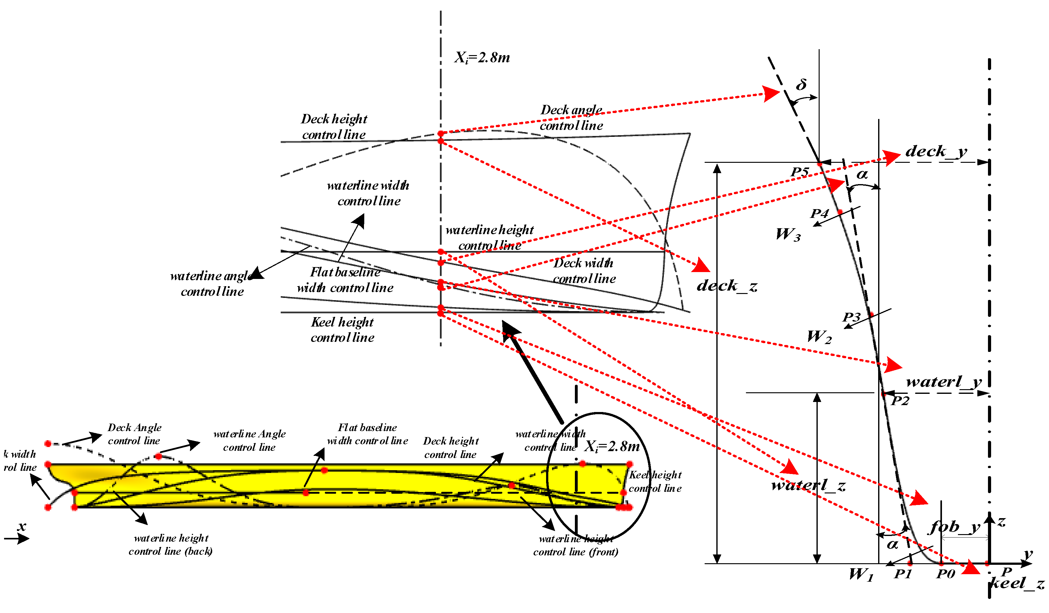
Figure 5. The red points in the figure are the constraint points at specific locations on the boundary curves, which can constrain the dimensions of the ship model in the length, width, and height directions as a whole. These parameters can show the hull geometry well and can be used as design variables to control the deformation of the hull during modeling, or as boundary or control curves for parameter constraints to assist the design. The meanings of the shapes shown in
Figure 5 are provided in
Table 2.
In the length direction, Ld0 and Ld1 are the x-coordinates of the front end of the deck line and the point at the maximum breadth amidships, respectively, and the x-coordinate of the rear end point is always 0; Lc0 and Lc2 are the x-coordinates of the front and rear end of the waterline, respectively. Finally, L0, L1, and L2 are the x-coordinates of the front end point, the point at the maximum width, and the rear end point of the flat-bottomed line, respectively. In the width direction, the first and last ends of the deck line, waterline, and flat-bottomed line intersect with the mid-longitudinal section, so the y-coordinate of each one is 0. The waterline and deck line have equal width, represented by Bd1 amidships; parameter B1 is the maximum breadth of the flat-bottomed line amidships. Similarly, in the height direction, since the flat-bottomed line is located on the baseline, its z-coordinate is 0, which is a fixed value; the heights of the head and tail ends of the waterline are expressed by Hc0 and Hc2, respectively, while the height of the deck line is expressed by Hd.
In addition to the three parameters of length, width, and height, there are also control parameters of angle and weight factors. The angle is introduced in three views: section, profile, and plan view. Here, the angle between the tangent line of the cross-section curves at the deck and the waterline and the
z-axis is controlled by the longitudinal feature curves. The curves are designed as the front and rear parts, and their maximum values in the front and rear parts of the hull are taken as the feature parameters (the specific values are designed when generating the longitudinal feature curves), which are denoted as
αb,
αf, and
δb,
δf (the same geometric meanings as
α and
δ in
Figure 6, where they are indicated as the maximum values).
Figure 5c shows the keel line diagram of the bow of the hull in the profile view (
xz plane), where
θc and
θd are the angles between the tangent lines (dashed lines) of the keel line at
Pc and
Pd, respectively, and the
z-axis.
Figure 5b shows the main boundary curve diagram in the
xy plane, where
βd and
γd represent the angles between tangent lines at points of the head and tail ends of the deck line and the
x-axis, respectively, and are mainly used to change the shape of the deck line. The tangential angle at points of the head and tail ends of the flat-bottomed line in the figure are always 0 with respect to the
x-axis, while the shape of the waterline is jointly determined by several parameters, and the tangential angle is not taken as a parameter here. The weighting factor of point
Pk in
Figure 5c is denoted as
Wk.
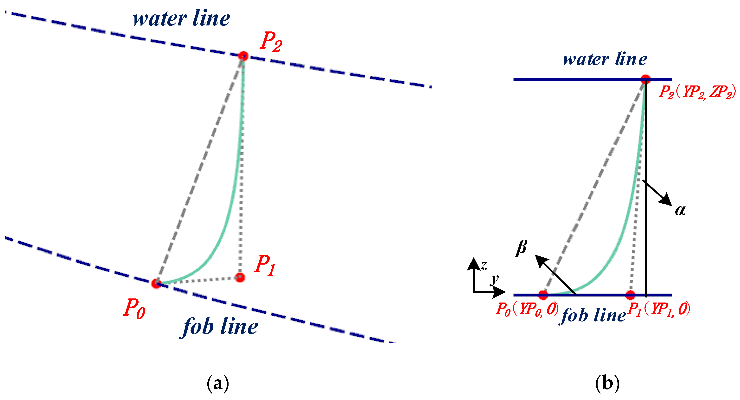
The parameters in the third category are used to control the shape of the cross-section curves.
Figure 6 shows a schematic diagram of the cross-section curve at a certain point of the hull (the modeling principle of this curve is described in later sections, and only the meaning of the feature parameters is introduced here).
α is the angle between the tangent line (dashed line) and the
z-axis at point
P2 of this cross-section curve and δ is the angle between the tangent line and the
z-axis at point
P5 of the curve.
deck_y and
deck_z are the width and height of the deck on this cross-section curve, i.e., the
y- and
z-coordinates at point
P5; similarly,
waterl_y and
waterl_z are the width and height corresponding to the waterline, i.e., the
y- and
z-coordinates at point
P2;
fob_y is the width of the flat-bottomed line and
keel_z is the height of the keel line. Weighting factor
w can control the shape of the curves and is introduced in the cross-section curve building section. The weight factors of points
P1,
P3, and
P4 in
Figure 6 are denoted as
W1,
W2, and
W3, respectively.
3.2. Generation of Longitudinal Feature Curves
Among the feature parameters described above, some have a specific value that does not change with the change in
Xi position in the captain’s direction, including parameters in the first and second categories such as
Ld0,
Bd1,
Hd, etc. Some parameters do not have a fixed value and take different values at different x positions in the captain’s direction, including parameters in the third category, such as the
α and
δ angles of cross-section curves, and the width and height of boundary curves, such as flat-bottomed line and deck line. These parameters should be established in the longitudinal direction corresponding to the smooth NURBS curves to control their values with the
Xi position change in the captain’s direction; usually these kinds of curves are called longitudinal feature curves. Based on the third category of feature parameters given in
Table 2, theoretically, 11 longitudinal feature curves need to be designed to control the variation in these parameters. Among them, the weight factor can be varied or fixed relative to the ship’s captain; it is taken as fixed here, so only 8 longitudinal feature curves need to be designed to control the generation of the cross-section curves. The purpose of this research was to design a ship independently according to the designer’s needs while ensuring the overall features of the Series 60 ship. Since the parametric hull form is closely related to the feature parameters and curves, the design of feature curves is crucial.
Figure 7 shows a schematic diagram of the designed longitudinal feature curves. As can be seen from the figure, for the deck width and waterline width control lines, their values are designed to be equal in the middle region of the Series 60 hull, and together with the flat-bottomed line width control line, they reach maximum values
Bd1 and
B1 at
Ld1 and
L1, respectively. As they continue to extend toward the head and tail ends, their values decrease, and eventually both the deck and waterline width drop to 0 at the bow
L0 and stern
L2, and similarly the flat-bottomed line width control line drops to 0 at the first area
L0 and the last area
L2. The height of the deck is controlled by the deck height control line. The waterline height control line is divided into two parts that control the change in waterline height values; a boundary curve, the keel line height control line, is designed to control the change in keel line height, and the specific shape is shown in
Figure 7. For the angle control line, the values of angles
α and
δ are set to 0 amidships, where angle
δ increases continuously toward the stern until it reaches the maximum value
δb at the stern end, with a trend of increasing and then decreasing in the direction of the bow, reaching the maximum value
δf at
Xi = 2.9 m. The angle increases and then decreases in both directions of bow and stern, and reaches the maximum values
αb,
αf at
Xi = 0.6 and 2.52 m. The distribution and variation in these longitudinal feature curves are illustrated in
Figure 7.
Figure 7 shows a schematic diagram of longitudinal feature curves in the
xz plane. Due to the large magnitude of various angular values, they are reduced by 100 times to be displayed in the
xz plane; meanwhile, the control lines in the width direction are in the
yz plane, and for display convenience, are rotated 90° around the x-axis so that they are in the
xz plane and displayed together with the other control lines. These longitudinal feature curves are created based on the NURBS technique, and each curve is selected with a suitable number of points for control. To better illustrate the curve creation process, the flat-bottomed line width control line is taken as an example.
Figure 8 shows a schematic diagram of the flat-bottomed line width control feature curve, which consists of two-part back and front curves; both are cubic NURBS curves with four control points and the weight factors of the middle control points are 1.4 and 1.2, calculated by Equation (3), and finally the two curves are connected smoothly by the NURBS expression combination curve technique.
In the same way, other feature curves can be designed, which is not described here. The longitudinal feature curves determine the specific values of various parameters in different cross-sections, which in turn determine the specific shapes of the cross-section curves and play a crucial role in the generation and deformation of the hull surface.
3.3. Definition of Cross-Section Shape
After the longitudinal feature curves are created, the next step is to create the typical shape of the cross-section curve needed for the parametric ship model. Based on the third category of feature parameters obtained in the previous analysis, the cross-section curve is divided into three parts: between the deck line and the waterline (upper curve), between the waterline and the flat-bottomed line (middle curve), and from the flat-bottomed line to the keel line (lower curve). At different x-positions, although its shape varies, the cross-section curve at each stop intersects the boundary curves (deck line, water line, flat-bottomed line, keel line), i.e., the starting and ending positions of the three parts of the curve are uniquely determined for the cross-section curve at the determined x-position. Therefore, the first step is to determine the intersection points of the corresponding cross-section curves with boundary curves on the different X-planes, Xi, i = 1, q, of the captain’s range, and then determine the coordinate information of each control point.
Cross-section curves are also NURBS curves in nature, and they differ from longitudinal feature curves in that they require special definitions. The cross-section curves of the hull can be convex, concave, or straight, and they have different shapes at different positions in the direction of the length and depth of the ship. For example, part of the cross-section curve in the parallel middle body of a bulk carrier is straight, while in the bulbous bow part, it is convex outward. At the invisible bulbous bow, part of the cross-section line is concave inward. Similarly, the shape of the cross-section curves in the z-direction of the parallel middle body part of the bulk carrier not only is straight, but the curve in the bilge keel part is outwardly convex. Clearly, different types of ships have different shapes of cross-section curves, and we need to control the curves to be convex, concave, or straight according to the design requirements.
According to the features of the Series 60, the hull form of the whole ship from the stern to the bow has similar features. Here, a typical shape of cross-section curve is chosen to express the hull surface, which has a general shape as follows: the first part of the curve is concave, the second part is convex, and the third part is straight. Therefore, a set of
q cross-section curves is defined according to this feature. In order to ensure smooth connection of each section of the curve, the cross-section part above and below the waterline is controlled by the third NURBS curve with four control points and the second NURBS curve with three control points, respectively. The third part of the straight-line section is controlled by the primary NURBS curve with two control points. The general form of the NURBS curve of the
pth degree with
n + 1 control points is shown as follows:
- (1)
Definition of the lower curve
This part of the curve is a primary NURBS curve with two control points, with the following equation:
The starting point,
V0(
YV0,
ZV0), and ending point,
V2(
YV2,
ZV2), of this primary (second-order) NURBS curve are the intersection of the cross-section curve with the keel line and the waterline, respectively, as shown in
Figure 9.
- (2)
Definition of the middle curve
Next, the establishment of the second part of the curve is introduced. This part of the curve is controlled by a quadratic NURBS curve with three control points, and the formula is as follows:
The starting point,
P0(
YP0,
ZP0), and ending point,
P2(
YP2,
ZP2), of the curve are the intersection points of the cross-section curve with the flat-bottomed line and waterline, respectively. For a certain cross-section, the positions of
P0 and
P2 are uniquely determined, so the degree of concavity and convexity of the curve can only be controlled by the intermediate point
P1.
Figure 10a shows the relative positional relationship between the second part of the curve and the waterline and flat-bottomed line in space;
Figure 10b shows the shape of the curve on the
X-plane. Among them, points
P0 and
P1 are both on the base plane, and the
z-coordinates
ZP0 and
ZP1 are both 0. Since
P0 and
P2 are the intersections of the curves,
YP0,
YP2, and
ZP2 are also determined. Then, we determine the
y coordinate of
P1 to determine the shape of the curve. The coordinates of point
P1 are determined by the following relation:
Among them, α represents the angle between the tangent line at the point P2 of the middle curve and the z-axis, which can be used as a parameter to control the deformation of the curve; angle β between the curve at point P0 and the y-axis is 0, so the Z-coordinate of P1 is always 0. The middle curve is located in the middle of the three-segment curve, the lower part is connected with the straight line, and the upper part is connected with the cubic NURBS curve, so ensuring the smoothness of the connection is a key issue. Introducing the angle between the end point of the curve and the coordinate axis solves this problem very well. By establishing the relational Formula (7), angles α and β are related to intermediate control point P1 of the NURBS curve. Additionally, the coordinates of the control points of the connected curves at both ends can be changed by changing the value of the angles, to finally realize the smooth connection of the curves at both ends.
In addition, weight factor
w of the intermediate point
P1 can also control the shape of the curve.
Figure 11 shows the shape change in the curve when weight factor
w changes from 1.1 to 1.5. This indicates that the smaller the weight factor, the smaller the degree of convexity of the curve, and the larger the weight factor, the greater the degree of convexity. Therefore, by introducing weight factor
w of
P1, a richer curve shape can be obtained. Here, the weight factor of
P1 is denoted as parameter
W1.
- (3)
Definition of the upper curve
The last part is the curve between the waterline and the deck line. The lower end of this part of the curve is at the point
P2(YP2,ZP2), which is connected to the quadratic NURBS curve, and the angle between the tangent line at the connection (the position of point
P2) and the
z-axis is α (the same angle
α as the middle curve). The upper end point is
P5(YP5,ZP5), which intersects with the deck line, and the included angle between the intersection and the
z-axis is the side edge of the deck, and is recorded as
δ. The left side of
Figure 12 shows the spatial position relationship of each curve, and the right side shows the shape of the curve on the
X plane.
With the above analysis, the geometric problem is transformed into an attempt to find a NURBS curve starting from point
P2 with starting angle
α to angle
δ reaching
P5.
Figure 13 shows a graphical representation of this geometric problem. This part of the curve can be controlled by a cubic NURBS curve with four control points, with the following equation:
Among them, the coordinate information of intermediate control points
P3(YP3,ZP3) and
P4(YP4,ZP4) are unknown, and starting point
P2 and ending point
P5 are the intersection points of the cross-section curve with the waterline and deck line, respectively; their coordinates are known as the coordinate constraints of the starting and ending points of this curve. The second constraint is the tangential angle of the starting and ending points of the curve:
. The third constraint is that distance
u1 from
P3 to
P2, distance
u2 from
P2 to
P5, and the distance from
P2 to
P5 satisfy the following relationship equation:
Using the above information, the coordinates of
P3 and
P4 can be found:
The weight factors of control points P3 and P4, denoted as parameters W2 and W3, respectively, can also influence the shape of the curves. The cross-section curves established by this method can meet the design requirements and achieve a smooth connection between curves.
Three NURBS curves are defined by the curves in the previous section, and finally these three curves are connected into one NURBS curve by the NURBS expression composition curve technique, forming a typical cross-section curve. It can better express the hull form features of the Series 60 ship and control its specific form at different positions
Xi by longitudinal feature curves, and finally a set of
q cross-section curves with different shapes can be obtained (gray curve in
Figure 14). The position
Xi = 2.8 m is selected as an example, and
Figure 14 (right) shows a schematic diagram of the cross-section curves at this position.
In the above cross-section example, the coordinates of each control point (P,P0, …,P5) are arbitrary, while in the actual hull modeling process, the shape of the cross-section curve at each station is determined, i.e., the coordinates of each control point are also determined, so there should be several specific curves to control the variation in the information of these parameters. From the previous parametric design methods, it is known that the information of form parameters of the cross-section curves is determined by the longitudinal feature curves, i.e., the longitudinal feature curves contain all the information of form parameters of the cross-section curve at each station; thus, linking the ship form with the feature parameters and feature curves.
Still using
Xi = 2.8 m position as an example,
Figure 14 shows the process of associating the longitudinal feature curves with the form control parameters of the cross-section curve at this position. First, a line perpendicular to the
x-axis is created in the
xz plane at
Xi = 2.8 m. This line intersects with each longitudinal feature curve (width, angle, height control lines, etc.) at a point. The
Z-coordinates of these intersection points are transmitted as parameter information to the corresponding control points on the cross-section curve, which in turn causes the information of the control points to change, and finally makes the shape of the cross-section curve change according to the requirements of the longitudinal feature curves. If such an association is established, the cross-section curves can be arranged in a regular and orderly manner along the captain’s direction by changing the longitudinal feature curves.
According to the correlation process shown in
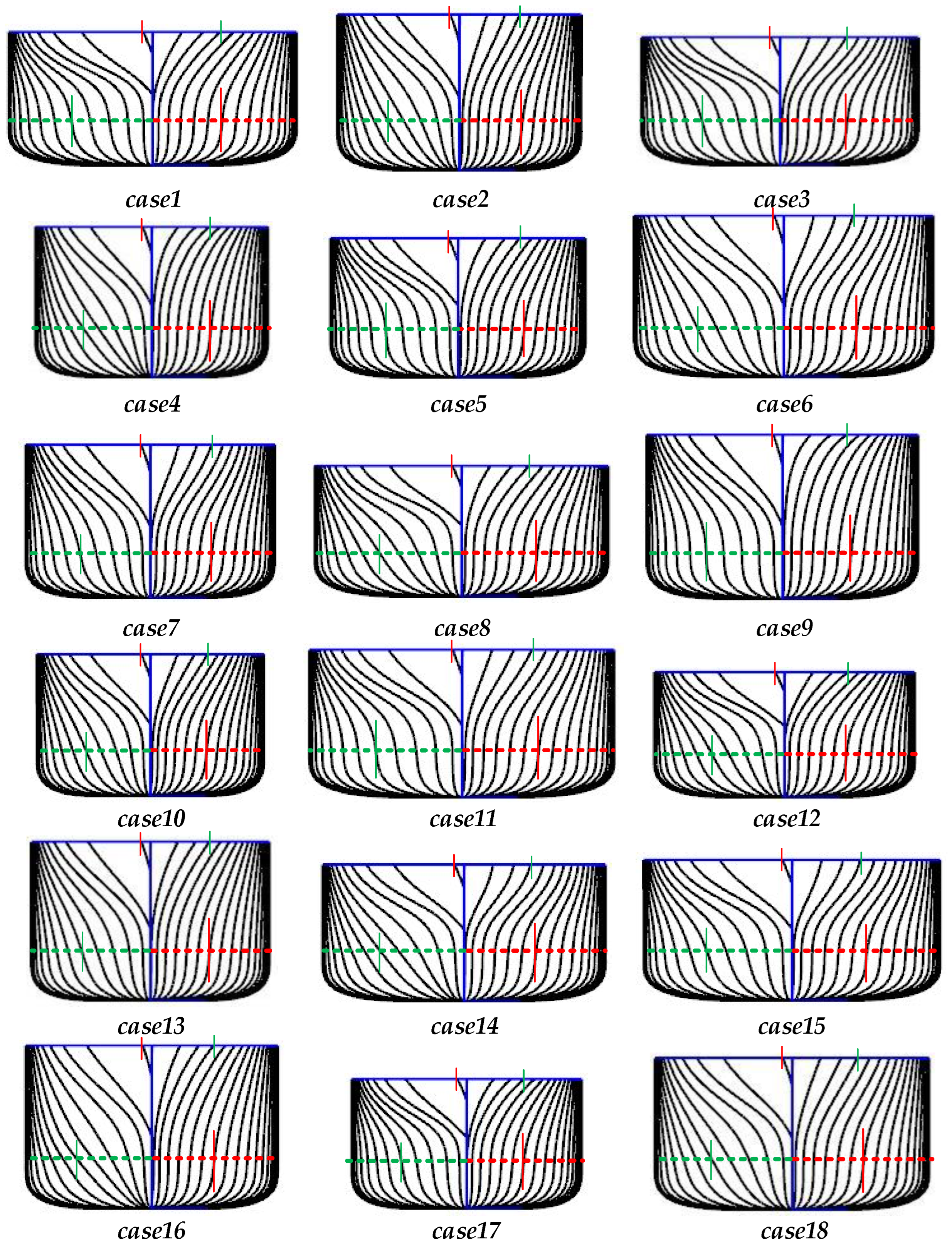
Figure 15, the Series 60 vessel is made to generate a cross-section curve every 0.065 m under the control of the longitudinal feature curve, and each cross-section curve satisfies the constraint of the boundary curve; the final generated cross-section curve is shown in
Figure 16. In the figure, the left side is the cross-section curve of the stern, the right side is the cross-section curve of the bow, the dashed brown line is the cross-section curve at position
Xi = 2.8 m, and the red points are its various control points.


