Review on Fixed and Floating Offshore Structures. Part II: Sustainable Design Approaches and Project Management
Abstract
1. Introduction
2. Design Considerations
2.1. Operational Factors
2.1.1. Location
2.1.2. Function
2.1.3. Orientation
2.1.4. Water Depth, Waves and Current
2.1.5. Deck Elevation
2.2. Environmental Factors
2.3. Loading Factors
- Operating environmental parameters, including dead loads and maximum live loads, that are appropriate for the platform’s usual operations;
- Operating environmental parameters, including dead loads and minimum live loads that are adequate for the platform’s usual operations;
- Establish environmental factors in the design with maximum live loads and dead loads that can be combined with extreme conditions;
- Establish environmental conditions in the design with a minimum of dead loads and a maximum of live loads that can be combined with harsh conditions;
- Environmental loads should be factored in according to the likelihood of any simultaneous occurrences in the loading scenario under consideration, except seismic loading. Where applicable, a seismic (or earthquake) load should be applied to the platform as a distinct environmental loading condition;
- The operating environment should be realistic of the platform’s relatively severe weather conditions. They do not have to be hard and fast rules that cause the platform to shut down if they’re broken. In the Gulf of Mexico, a 5-year winter storm from 1-year weather is typically employed as an operational condition, however recent designs have longer design times as seen in API 2MET-INT;
- Both production and drilling platforms should have a maximum live load that takes into account production, drilling, and work over mode loadings, as well as any acceptable combinations of drilling or work over operations with production;
- To maximise design stress in the platform members, consider variability in supply weights and the positions of mobile equipment such as a drilling derrick.
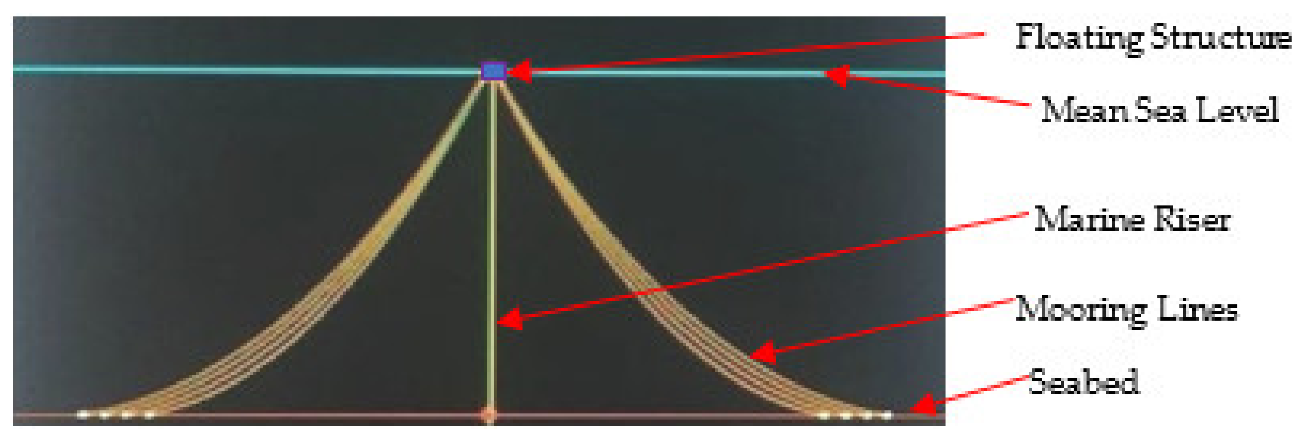
2.4. Structural Attachments: Mooring lines and Marine Risers
3. Classifying Design Loads
3.1. Live Loads
- The weight of drilling and production machinery and related equipment that can be added to the platform or taken away from it is part of the live loads;
- The weight of the platform’s heliport, platform’s living quarters, and other life support equipment (LSE), as well as diving, utility, and life-saving equipment that can be added or withdrawn;
- The weight in storage tanks of drilling fluids, other liquids and consumable supplies are part of live loads. Operations such as helicopter loadings, drilling, offloading, vessel mooring, and material handling, impose forces on the structure;
- The stresses exerted on the structure from the use of a deck crane are all part of external forces. The suspended load, the platform motion, and the dead load are used to calculate these forces.
3.2. Dead Loads
3.3. Gravitational Loads
3.3.1. Removal and Reinstallation Loads
3.3.2. Dynamic Loads
3.3.3. Impact Loads
3.4. Environmental Loads
3.5. Wave Load
3.6. Wind Load
- The average length of stay for a guest is averagely less than 1 min or longer timeframe. Wind data should be normalized to a standard elevation, (for example 8 m) above the mean water level, then averaged for one hour. Using standard profile and guest variables, wind data can be changed to any desired averaging time or elevation;
- In some cases, the speed around the average wind spectrum and its changes should be supplied. Complaint structures in deep water, such as tension leg platforms and guyed towers, may have a natural sway time of one minute or more, during which significant energy is lost due to wind speed fluctuations;
- For each month or season, the frequency with which specific sustained wind speed occur from distinct directions;
- The persistent occurrence of sustained wind speeds exceeding prescribed levels from season after season or month after month.
4. Sustainable Design Approaches
4.1. Designing with Environmental Conditions
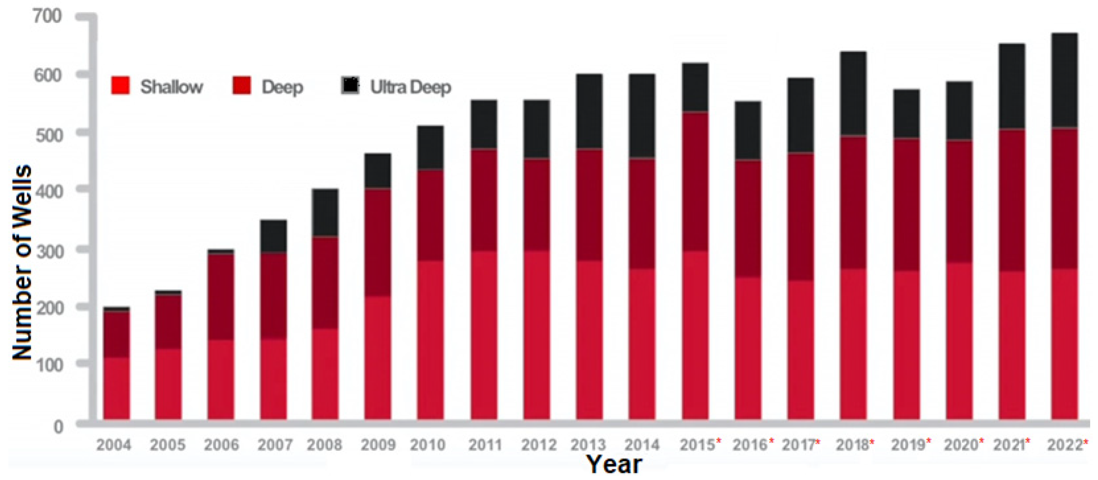
4.2. Designing with Water Depth
4.3. Software for Designing with Geotechnical Information
4.4. Software for Platform Designs and Rendering
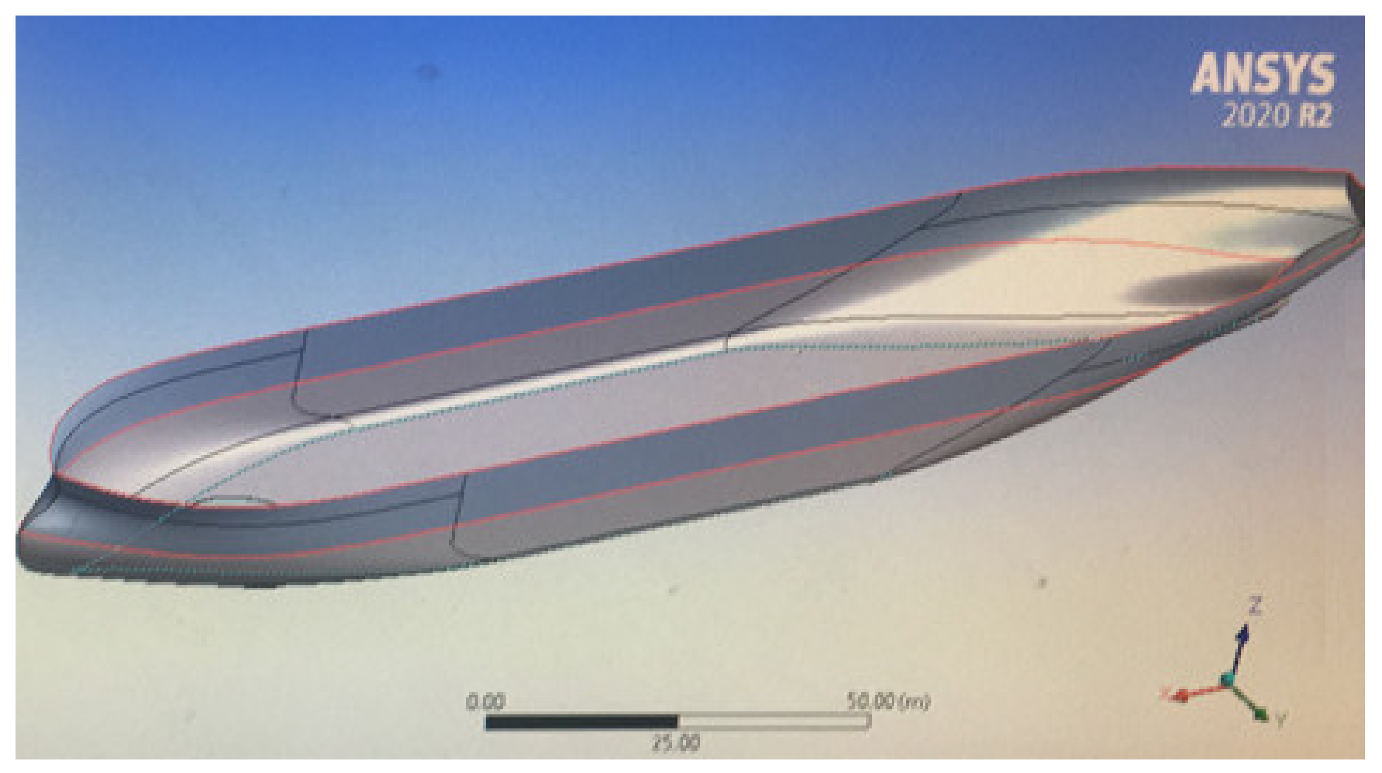
- General purpose finite element programs: ANSYS, ABAQUS, COMSOL, etc;
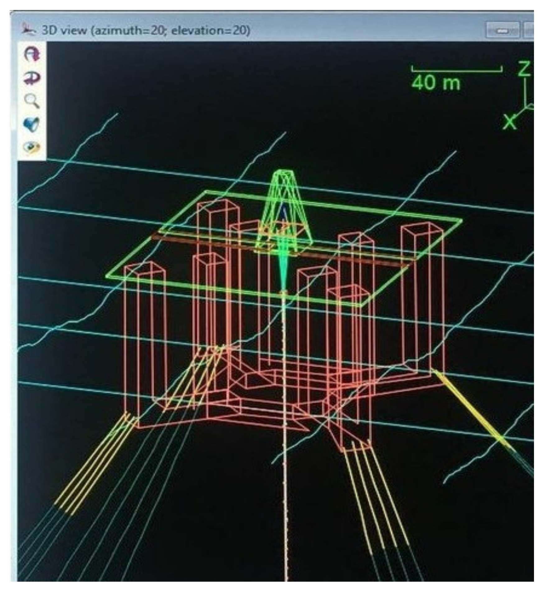
- Riser Analysis Tools: Orcaflex, Riflex, Flexcom, etc;
- Riser VIV Analysis Tools: VIVANA, VIVA, DeepVIV, Shear7, etc.;
- Coupled motion analysis programs: HARP, etc;
- Riser Installation Analysis Tools: Pipelay, Orcaflex, OFFPIPE, etc.
- Riser, pile and motion interaction using CFD based programs: ANSYS Fluent, ANSYS CFX, OpenFOAM, Simscale, STAR-CCM+, FAST, etc.
4.5. Construction and Fabrication
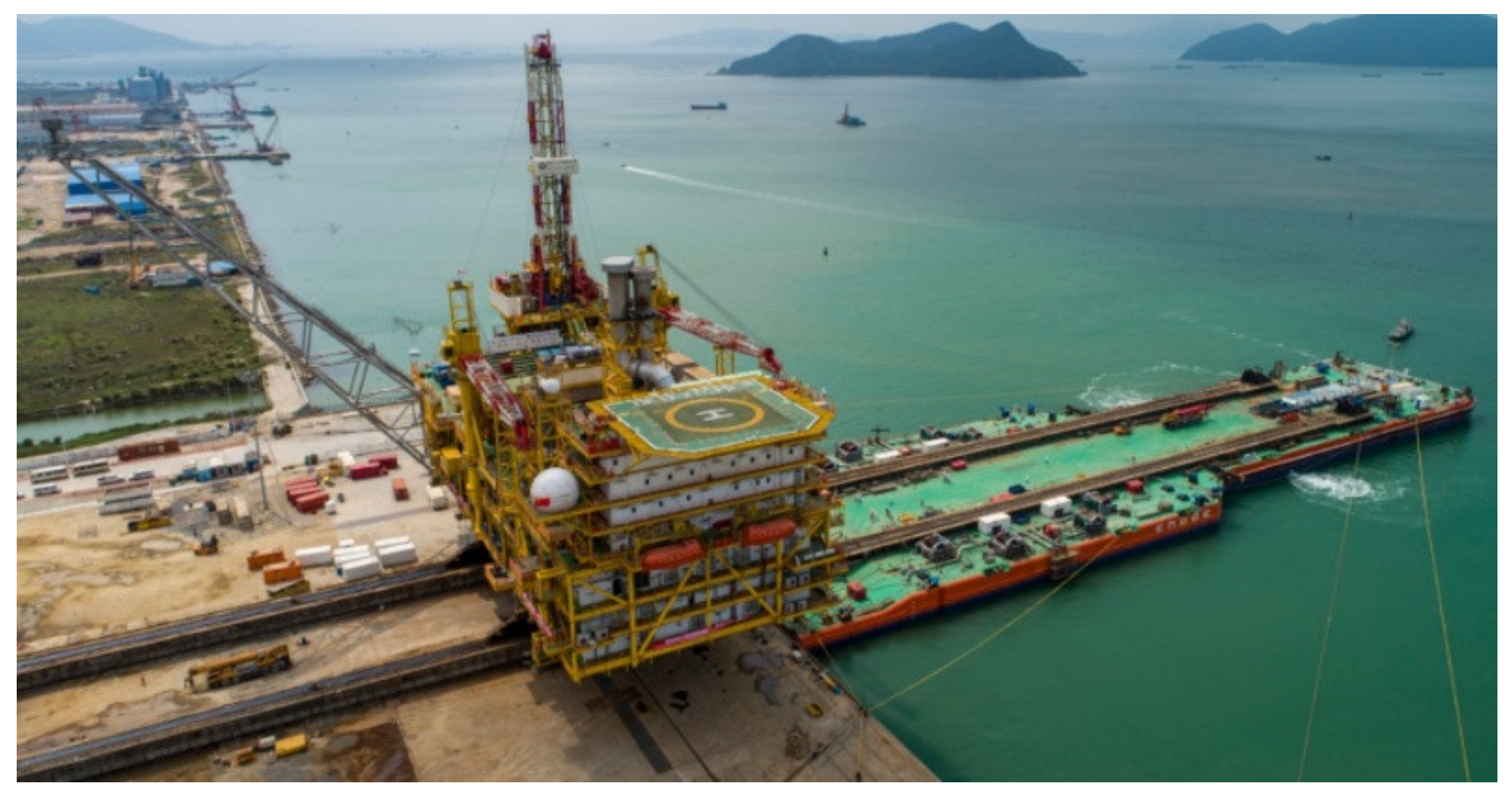
4.6. Loadout and Transportation
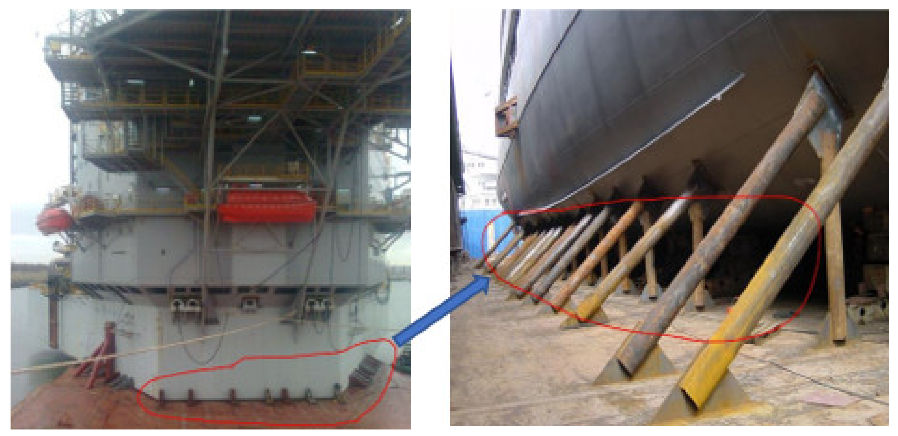
4.7. Sea Fastening Operations
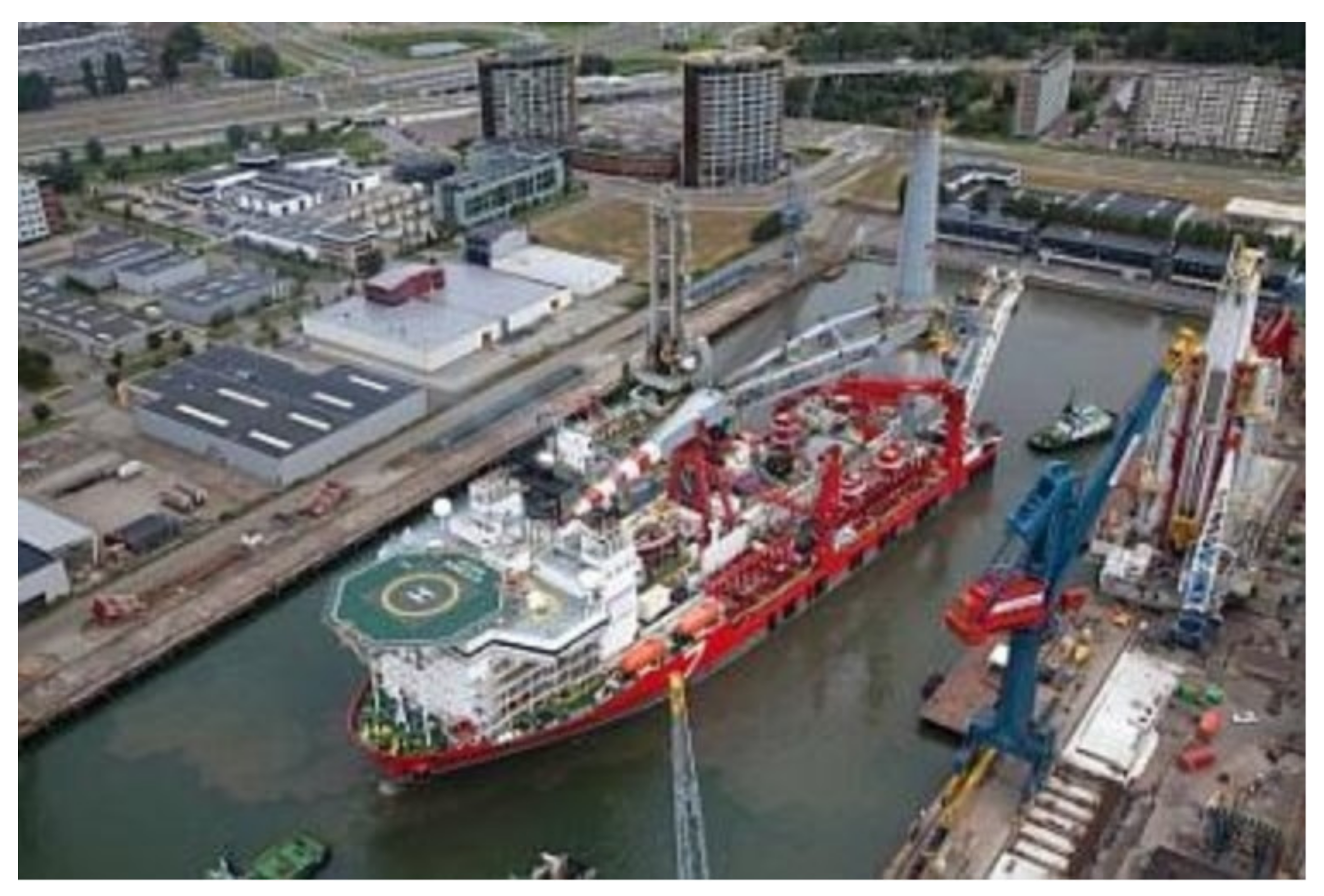
4.8. Lifting, Launching and Upending
4.9. Floatover Installation and Platform Integration
5. Project Management of Offshore Facilities
5.1. Planning Offshore Projects
- Survey of the construction site;
- Site visits and dive inspections on the installation site;
- Investment feasibility studies, and;
- Procurement;
- Design approval by governing authorities;
- Preparation of platform elements for transportation;
- Fabrication of steel structures;
- Transportation, and installation procedures;
- Loadout;
- Sorting offshore installation processes;
- Commissioning.
5.2. Pricing Offshore Projects
5.3. Conducting Material Checks
5.4. Conducting Design Checks
- Initial transportation needs;
- Environmental (weather, and in-place 100-year storm conditions);
- Soil characteristics;
- Code requirements;
- Intensity degree of failure consequences.
5.5. Conducting Document Checks
- ❖ In-place analysis or On-the-spot analysis;
- ❖ Seismic Analysis;
- ❖ Fatigue Analysis;
- ❖ Extreme loads analysis;
- ❖ Temporary assessment;
- ❖ Loadout assessment;
- ❖ Transportation assessment;
- ❖ Appurtenance assessment;
- ❖ Lift/Launch assessment;
- ❖ Upending assessment;
- ❖ Uprighting assessment;
- ❖ Unpiled stability assessment;
- ❖ Drivability study of piles and conductor pipes;
- ❖ Cathodic protection analysis;
- ❖ Transportation analysis;
- ❖ Installation analysis.
5.6. Obtaining Client Permits and Approval Process
5.7. Project Management Stages
6. Conclusions and Recommendations for Future Research
Author Contributions
Funding
Institutional Review Board Statement
Informed Consent Statement
Acknowledgments
Conflicts of Interest
Abbreviations
| 2D | Two-Dimensional |
| 3D | Three-Dimensional |
| AISC | American Institute of Steel Construction |
| ANN | artificial neural network |
| API | American Petroleum Institute |
| ASTM | American Society for Testing and Materials |
| BOP | Blowout Preventer |
| CFD | Computational Fluid Dynamics |
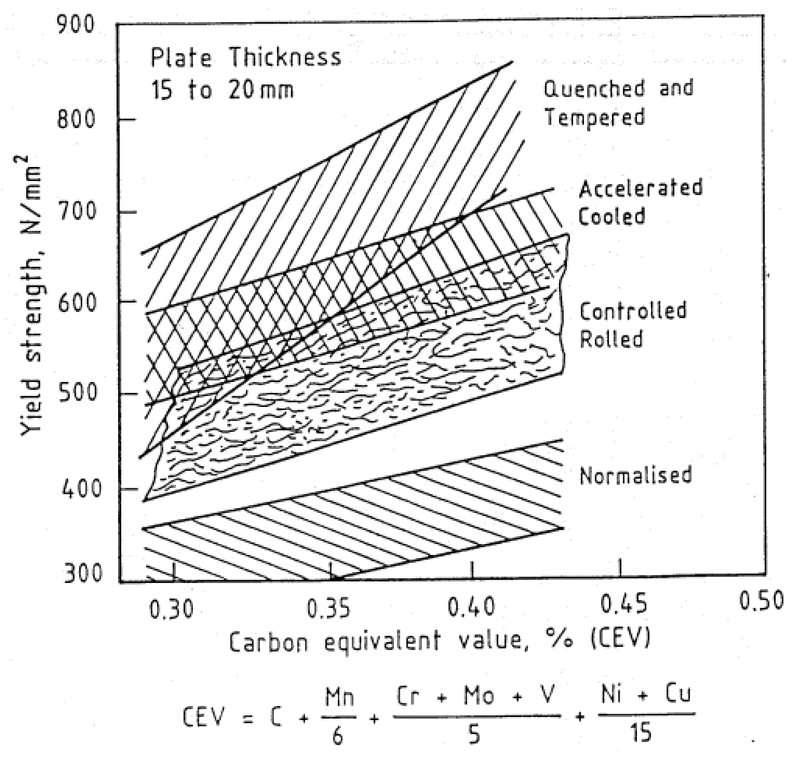
| CEV | Carbon Equivalent Value |
| CPU | Central Processing Unit |
| DD | Semi Deep Draft Semisubmersible |
| DNV | Det Norske Veritas |
| DoF | Degree of Freedom |
| DTS | Dry-Tree Semisubmersible |
| FOWT | Floating Offshore Wind Turbine |
| FPSO | Floating, Production, Storage and Offloading |
| GA | genetic algorithm |
| GoM | Gulf of Mexico |
| GPU | Graphics Processing Unit |
| h/L | Relative water depth or Ratio of mean water depth to wave length |
| HSE | Health and Safety Executive |
| LSE | Life Support Equipment |
| MET-INT | Metocean Interim |
| MOPU | Mobile Offshore Production Unit |
| NA | Not Applicable |
| NREL | National Renewable Energy Laboratory |
| RAO | Respond Amplitude Operator |
| RP | Recommended Practice |
| SCR | Steel Catenary Risers |
| SemiSub | SemiSubmersible |
| SPAR | Single Point Anchor Reservoir |
| TLP | Tension Leg Platform |
| TTR | Top Tension Riser |
| U.S.A. | United States of America |
| VIV | Vortex Induced Vibration |
| VLFS | Very Large Floating Structures |
| WEC | Wave Energy Converter |
| WSD | Working Stress Design |
Appendix A

References
- Chakrabarti, S.K. Handbook of Offshore Engineering, 1st ed.; Elsevier: Plainfield, IL, USA, 2005; Volume 1. [Google Scholar]
- Haritos, N. Introduction to the analysis and design of offshore structures—An overview. Electron. J. Struct. Eng. 2007, 7, 55–65. Available online: https://ejsei.com/EJSE/article/download/65/64 (accessed on 12 February 2022).
- Yu, L.C.; King, L.S.; Hoon, A.T.C.; Yean, P.C.C. A Review Study of Oil and Gas Facilities for Fixed and Floating Offshore Platforms. Res. J. Appl. Sci. Eng. Technol. 2015, 10, 672–679. [Google Scholar] [CrossRef]
- Amiri, N.; Shaterabadi, M.; Kashyzadeh, K.R.; Chizari, M. A Comprehensive Review on Design, Monitoring, and Failure in Fixed Offshore Platforms. J. Mar. Sci. Eng. 2021, 9, 1349. [Google Scholar] [CrossRef]
- Amaechi, C.V.; Reda, A.; Butler, H.O.; Ja’e, I.A.; An, C. Review on fixed and floating offshore structures. Part I: Types of platforms with some applications. JMSE 2022. under review. [Google Scholar]
- Al-Sharif, A.A. Design, Fabrication and Installation of Fixed Offshore Platforms in the Arabian Gulf. In Proceedings of the Fourth Saudi Engineering Conference, Nashville, TN, USA, 5–8 November 1995; Saudi Arabian Oil Company: Dhahran, Saudi Arabia, 1995; Volume 1995, pp. 99–105. [Google Scholar]
- Bai, Y.; Bai, Q. Subsea Engineering Handbook; Elsevier: Oxford, UK, 2010. [Google Scholar]
- Wilson, J. Dynamics of Offshore Structures, 2nd ed.; John Wiley & Sons: Hoboken, NJ, USA, 2002. [Google Scholar]
- Ladeira, I.; Márquez, L.; Echeverry, S.; Le Sourne, H.; Rigo, P. Review of methods to assess the structural response of offshore wind turbines subjected to ship impacts. Ships Offshore Struct. 2022, 2022, 1–20. [Google Scholar] [CrossRef]
- Jaculli, M.A.; Leira, B.J.; Sangesland, S.; Morooka, C.K.; Kiryu, P.O. Dynamic response of a novel heave-compensated floating platform: Design considerations and the effects of mooring. Ships Offshore Struct. 2022, 2022, 1–11. [Google Scholar] [CrossRef]
- Saiful Islam, A.B.M.; Jameel, M.; Jumaat, M.Z.; Shirazi, S.; Salman, F.A. Review of offshore energy in Malaysia and floating Spar platform for sustainable exploration. Renew. Sustain. Energy Rev. 2012, 16, 6268–6284. [Google Scholar] [CrossRef]
- Muyiwa, O.A.; Sadeghi, K. Construction planning of an offshore petroleum platform. GAU J. Soc. Appl. Sci. 2007, 2, 82–85. [Google Scholar]
- Sadeghi, K.; Al-koiy, K.; Nabi, K. General Guidance for The Design, Fabrication and Installation of Jack-Up Platforms. Asian J. Nat. Appl. Sci. 2017, 6, 77–84. Available online: http://www.ajsc.leena-luna.co.jp/AJSCPDFs/Vol.6(4)/AJSC2017(6.4-08).pdf (accessed on 22 May 2022).
- Sadeghi, K. An Overview on Design, Construction and Installation of Offshore Template Platforms Suitable for Persian Gulf Oil/Gas Fields. In Proceedings of the First International Symposium on Engineering, Artificial Intelligence and Applications, Girne, Cyprus, 6–8 November 2013. [Google Scholar]
- Sadeghi, K. Significant guidance for design and construction of marine and offshore structures. GAU J. Soc. Appl. Sci. 2008, 4, 67–92. Available online: https://www.researchgate.net/publication/250310894_Significant_Guidance_for_Design_and_Construction_of_Marine_and_Offshore_Structures (accessed on 6 July 2022).
- Sadeghi, K.; Dilek, H. An Introduction to the design of Offshore Structures. Acad. Res. Int. 2019, 10, 19–27. Available online: http://www.savap.org.pk/journals/ARInt./Vol.10(1)/ARInt.2019(10.1-03).pdf (accessed on 12 February 2022).
- Wu, P.; Zhang, Y.; Pang, S.; Wu, Z. Nonlinear vibration analysis of deepwater top tension riser under drilling condition. J. Dyn. Control. Phys. Rev. Lett. 2019, 17, 112–120. [Google Scholar]
- Liao, M.; Wang, G.; Gao, Z.; Zhao, Y.; Li, R. Mathematical Modelling and Dynamic Analysis of an Offshore Drilling Riser. Shock Vib. 2020, 2020, 1–13. [Google Scholar] [CrossRef]
- Bernitsas, M.M.; Kokarakis, J.E.; Imron, A. Large deformation three-dimensional static analysis of deep water marine risers. Appl. Ocean Res. 1985, 7, 178–187. [Google Scholar] [CrossRef][Green Version]
- Patel, M.; Sarohia, S.; Ng, K. Finite-element analysis of the marine riser. Eng. Struct. 1984, 6, 175–184. [Google Scholar] [CrossRef]
- Burke, B.G. An analysis of Marine Risers for Deep Water. In Proceedings of the Offshore Technology Conference, Houston, TX, USA, 3–6 May 1973. [Google Scholar]
- Bae, Y.; Bernitsas, M.M. Importance of Nonlinearities in Static and Dynamic Analyses of Marine Riser. In Proceedings of the International Offshore and Polar Engineering Conference, Hague, The Netherlands, 11–16 June 1995. [Google Scholar]
- Wang, Y.; Gao, D.; Fang, J. Coupled dynamic analysis of deepwater drilling riser under combined forcing and parametric excitation. J. Nat. Gas Sci. Eng. 2015, 27, 1739–1747. [Google Scholar] [CrossRef]
- Amaechi, C.V.; Chesterton, C.; Butler, H.O.; Gillet, N.; Wang, C.; Ja’E, I.A.; Reda, A.; Odijie, A.C. Review of Composite Marine Risers for Deep-Water Applications: Design, Development and Mechanics. J. Compos. Sci. 2022, 6, 96. [Google Scholar] [CrossRef]
- Toh, W.; Bin Tan, L.; Jaiman, R.K.; Tay, T.E.; Tan, V.B.C. A comprehensive study on composite risers: Material solution, local end fitting design and global response. Mar. Struct. 2018, 61, 155–169. [Google Scholar] [CrossRef]
- Amaechi, C.V.; Gillett, N.; Odijie, A.C.; Hou, X.; Ye, J. Composite risers for deep waters using a numerical modelling approach. Compos. Struct. 2018, 210, 486–499. [Google Scholar] [CrossRef]
- Amaechi, C.V. Local tailored design of deep water composite risers subjected to burst, collapse and tension loads. Ocean Eng. 2022, 250, 110196. [Google Scholar] [CrossRef]
- Roberts, D.; Hatton, S.A. Development and Qualification of End Fittings for Composite Riser Pipe. In Proceedings of the Offshore Technology Conference, Houston, TX, USA, 6–9 May 2013. [Google Scholar]
- Amaechi, C.V.; Gillet, N.; Ja’E, I.A.; Wang, C. Tailoring the Local Design of Deep Water Composite Risers to Minimise Structural Weight. J. Compos. Sci. 2022, 6, 103. [Google Scholar] [CrossRef]
- Pham, D.-C.; Sridhar, N.; Qian, X.; Sobey, A.J.; Achintha, M.; Shenoi, A. A review on design, manufacture and mechanics of composite risers. Ocean Eng. 2016, 112, 82–96. [Google Scholar] [CrossRef]
- Wichers, I.J. Guide to Single Point Moorings; WMooring Inc: Houston, TX, USA, 2013; Available online: http://www.wmooring.com/files/Guide_to_Single_Point_Moorings.pdf (accessed on 17 May 2022).
- Petrone, C.; Oliveto, N.D.; Sivaselvan, M.V. Dynamic Analysis of Mooring Cables with Application to Floating Offshore Wind Turbines. J. Eng. Mech. 2015, 142, 1–12. [Google Scholar] [CrossRef]
- Mavrakos, S.; Papazoglou, V.; Triantafyllou, M.; Chatjigeorgiou, I. Deep water mooring dynamics. Mar. Struct. 1996, 9, 181–209. [Google Scholar] [CrossRef]
- Mavrakos, S.; Chatjigeorgiou, J. Dynamic behaviour of deep water mooring lines with submerged buoys. Comput. Struct. 1997, 64, 819–835. [Google Scholar] [CrossRef]
- Ja’E, I.A.; Ali, M.O.A.; Yenduri, A.; Nizamani, Z.; Nakayama, A. Optimisation of mooring line parameters for offshore floating structures: A review paper. Ocean Eng. 2022, 247, 110644. [Google Scholar] [CrossRef]
- Amaechi, C.V.; Odijie, A.C.; Wang, F.; Ye, J. Numerical investigation on mooring line configurations of a Paired Column Semisubmersible for its global performance in deep water condition. Ocean Eng. 2022, 250, 110572. [Google Scholar] [CrossRef]
- Xu, S.; Ji, C.-Y.; Soares, C.G. Experimental and numerical investigation a semi-submersible moored by hybrid mooring systems. Ocean Eng. 2018, 163, 641–678. [Google Scholar] [CrossRef]
- Xue, X.; Chen, N.-Z.; Wu, Y.; Xiong, Y.; Guo, Y. Mooring system fatigue analysis for a semi-submersible. Ocean Eng. 2018, 156, 550–563. [Google Scholar] [CrossRef]
- Wang, K.; Er, G.-K.; Iu, V.P. Nonlinear vibrations of offshore floating structures moored by cables. Ocean Eng. 2018, 156, 479–488. [Google Scholar] [CrossRef]
- Harnois, V.; Weller, S.D.; Johanning, L.; Thies, P.R.; Le Boulluec, M.; Le Roux, D.; Soule, V.; Ohana, J. Numerical model val-idation for mooring systems: Method and application for wave energy converters. Renew. Energy 2015, 75, 869–887. [Google Scholar] [CrossRef]
- Amaechi, C.V.; Wang, F.; Ye, J. Numerical studies on CALM buoy motion responses and the effect of buoy geometry cum skirt dimensions with its hydrodynamic waves-current interactions. Ocean Eng. 2021, 244, 110378. [Google Scholar] [CrossRef]
- Amaechi, C.V.; Wang, F.; Hou, X.; Ye, J. Strength of submarine hoses in Chinese-lantern configuration from hydrodynamic loads on CALM buoy. Ocean Eng. 2018, 171, 429–442. [Google Scholar] [CrossRef]
- Gao, Q.; Zhang, P.; Duan, M.; Yang, X.; Shi, W.; An, C.; Li, Z. Investigation on structural behavior of ring-stiffened composite offshore rubber hose under internal pressure. Appl. Ocean Res. 2018, 79, 7–19. [Google Scholar] [CrossRef]
- Amaechi, C.V.; Chesterton, C.; Butler, H.O.; Wang, F.; Ye, J. Review on the design and mechanics of bonded marine hoses for Catenary Anchor Leg Mooring (CALM) buoys. Ocean Eng. 2021, 242, 110062. [Google Scholar] [CrossRef]
- Amaechi, C.V.; Chesterton, C.; Butler, H.O.; Wang, F.; Ye, J. An Overview on Bonded Marine Hoses for sustainable fluid transfer and (un)loading operations via Floating Offshore Structures (FOS). J. Mar. Sci. Eng. 2021, 9, 1236. [Google Scholar] [CrossRef]
- Tonatto, M.L.; Tita, V.; Araujo, R.T.; Forte, M.M.; Amico, S.C. Parametric analysis of an offloading hose under internal pressure via computational modeling. Mar. Struct. 2017, 51, 174–187. [Google Scholar] [CrossRef]
- Gao, P.; Gao, Q.; An, C.; Zeng, J. Analytical modeling for offshore composite rubber hose with spiral stiffeners under internal pressure. J. Reinf. Plast. Compos. 2020, 40, 352–364. [Google Scholar] [CrossRef]
- Amaechi, C.V.; Wang, F.; Ja’E, I.A.; Aboshio, A.; Odijie, A.C.; Ye, J. A literature review on the technologies of bonded hoses for marine applications. Ships Offshore Struct. 2022, 1–32, (Ahead-of print). [Google Scholar] [CrossRef]
- Amaechi, C.V.; Wang, F.; Ye, J. Mathematical Modelling of Bonded Marine Hoses for Single Point Mooring (SPM) Systems, with Catenary Anchor Leg Mooring (CALM) Buoy application—A Review. J. Mar. Sci. Eng. 2021, 9, 1179. [Google Scholar] [CrossRef]
- Wang, Z.; Bai, Y.; Wei, Q. Mechanical properties of glass fibre reinforced pipeline during the laying process. Ships Offshore Struct. 2022, 2022, 1–8. [Google Scholar] [CrossRef]
- Liu, W.; Bai, Y.; Gao, Y.; Song, X.; Han, Z. Analysis of the mechanical properties of a reinforced thermoplastic composite pipe joint. Ships Offshore Struct. 2021, 2021, 1–7. [Google Scholar] [CrossRef]
- Liu, W.; Gao, Y.; Shao, Q.; Cai, W.; Han, Z.; Chi, M. Design and analysis of joints in reinforced thermoplastic composite pipe under internal pressure. Ships Offshore Struct. 2021, 17, 1276–1285. [Google Scholar] [CrossRef]
- Ochoa, O.; Salama, M. Offshore composites: Transition barriers to an enabling technology. Compos. Sci. Technol. 2005, 65, 2588–2596. [Google Scholar] [CrossRef]
- Langen, I.; Skjåstad, O.; Haver, S. Measured and predicted dynamic behaviour of an offshore gravity platform. Appl. Ocean Res. 1998, 20, 15–26. [Google Scholar] [CrossRef]
- Chandrasekaran, S.; Uddin, S.A.; Wahab, M. Dynamic Analysis of Semi-submersible Under the Postulated Failure of Restraining System with Buoy. Int. J. Steel Struct. 2020, 21, 118–131. [Google Scholar] [CrossRef]
- Tong, C. Advanced Materials and Devices for Hydropower and Ocean Energy. In Introduction to Materials for Advanced Energy Systems; Springer: Cham, Switzerland, 2019. [Google Scholar] [CrossRef]
- Anastasiades, K.; Michels, S.; Van Wuytswinkel, H.; Blom, J.; Audenaert, A. Barriers for the circular reuse of steel in the Belgian construction sector: An industry-wide perspective. Proc. Inst. Civ. Eng. Manag. Procure. Law 2022, 1–14. [Google Scholar] [CrossRef]
- Odijie, A.C.; Quayle, S.; Ye, J. Wave induced stress profile on a paired column semisubmersible hull formation for column reinforcement. Eng. Struct. 2017, 143, 77–90. [Google Scholar] [CrossRef]
- Chandrasekaran, S.; Gaurav, S. Design Aids for Offshore Structures under Special Environmental Loads, Including Fire Resistance; Springer: Singapore, 2017; ISBN 9789813221076087. [Google Scholar]
- Chandrasekaran, S.; Nagavinothini, R. Offshore Triceratops Under Impact Forces in Ultra Deep Arctic Waters. Int. J. Steel Struct. 2019, 20, 464–479. [Google Scholar] [CrossRef]
- Barltrop, N.D.P.; Adams, A.J. Dynamics of Fixed Marine Structures, 3rd ed.; Butterworth Heinemann: Oxford, UK, 1991. [Google Scholar]
- Brebbia, C.; Walker, S. Dynamic analysis of offshore structures. Appl. Ocean Res. 1981, 3, 205. [Google Scholar] [CrossRef]
- Chandrasekaran, S. Dynamic Analysis and Design of Offshore Structures; Springer: Singapore, 2018. [Google Scholar] [CrossRef]
- Leffler, W.L.; Pattarozzi, R.; Sterling, G. Deepwater Petroleum Exploration & Production: A Non-technical Guide; PennWell: Tulsa, OK, USA, 2011; ISBN 9781593702533. [Google Scholar]
- Fang, H.; Duan, M. Offshore Operation Facilities; Gulf Professional Publishing: Oxford, UK, 2014. [Google Scholar] [CrossRef]
- Aird, P. Deepwater Drilling: Well Planning, Design, Engineering, Operations, and Technology Application; Gulf Professional Publishing: Oxford, UK, 2019. [Google Scholar] [CrossRef]
- Saavedra, N.; Joshi, S. Application of Horizontal Well Technology in Colombia. J. Can. Pet. Technol. 2002, 41, 2. [Google Scholar] [CrossRef]
- Stewart, G. Well Test Design and Analysis; Pennwell Books: Tulsa, OK, USA, 2011. [Google Scholar]
- Azar, J.J.; Robello, S. Drilling Engineering; Pennwell Books: Tulsa, OK, USA, 2007. [Google Scholar]
- Samie, N.N. Disciplines Involved in Offshore Platform Design. In Practical Engineering Management of Offshore Oil and Gas Platforms; Elsevier: Amsterdam, The Netherlands, 2016; pp. 25–212. [Google Scholar] [CrossRef]
- Clews, R. Project Finance for the International Petroleum Industry; Elsevier: Cambridge, MA, USA, 2016; ISBN 9780128001585. [Google Scholar] [CrossRef]
- Chandrasekaran, S.; Jain, A.K. Ocean structures, Construction, Materials, and Operations; CRC Press: Norco, FL, USA, 2016; ISBN 9781498797429. [Google Scholar]
- Laik, S. Offshore Petroleum Drilling and Production, 1st ed.; CRC Press: Norco, FL, USA, 2018. [Google Scholar] [CrossRef]
- Speight, J.G. Subsea and Deepwater Oil and Gas Science and Technology; Gulf Professional Publishing: Oxford, UK, 2015. [Google Scholar] [CrossRef]
- Grace, R.D. Blowout and Well Control Handbook; Gulf Professional Publishing: Oxford, UK, 2017. [Google Scholar] [CrossRef]
- Renpu, W. Advanced Well Completion Engineering; Gulf Professional Publishing: Oxford, UK, 2011. [Google Scholar] [CrossRef]
- Byrom, T.G. Casing and Liners for Drilling and Completion, 2nd ed.; Gulf Professional Publishing: Oxford, UK, 2015. [Google Scholar] [CrossRef]
- Caenn, R.; Darley, H.; Gray, G.R. Composition and Properties of Drilling and Completion Fluids, 7th ed.; Gulf Professional Publishing: Oxford, UK, 2017. [Google Scholar] [CrossRef]
- Devereux, S. Practical Well Planning and Drilling Manual; Pennwell Books: Tulsa, OK, USA, 1998. [Google Scholar]
- Veatch, R.W.; King, G.E.; Holditch, S.A. Essentials of Hydraulic Fracturing: Vertical and Horizontal Wellbores; Pennwell Books: Tulsa, OK, USA, 2017. [Google Scholar]
- Raymond, M.S.; Leffler, W.L. Oil & Gas Production in Nontechnical Language; Pennwell Books: Tulsa, OK, USA, 2017. [Google Scholar]
- Crumpton, H. Well Control for Completions and Interventions; Gulf Professional Publishing: Oxford, UK, 2018. [Google Scholar] [CrossRef]
- Sadeghi, K. An Overview of Design, Analysis, Construction and Installation of Offshore Petroleum Platforms Suitable for Cyprus Oil/Gas Fields. GAU J. Soc. Appl. Sci. 2007, 2, 1–16. Available online: https://cemtelecoms.iqpc.co.uk/media/6514/786.pdf (accessed on 12 February 2022).
- Yan, J.; Qiao, D.; Ou, J. Optimal design and hydrodynamic response analysis of deep water mooring system with submerged buoys. Ships Offshore Struct. 2018, 13, 476–487. [Google Scholar] [CrossRef]
- Ormberg, H.; Larsen, K. Coupled analysis of floater motion and mooring dynamics for a turret-moored ship. Appl. Ocean Res. 1998, 20, 55–67. [Google Scholar] [CrossRef]
- Qiao, D.; Ou, J. Global responses analysis of a semi-submersible platform with different mooring models in South China Sea. Ships Offshore Struct. 2012, 8, 441–456. [Google Scholar] [CrossRef]
- Bargi, K.; Hosseini, S.R.; Tadayon, M.H.; Sharifian, H. Seismic Response of a Typical Fixed Jacket-Type Offshore Platform (SPD1) Under Sea Waves. Open J. Mar. Sci. 2011, 1, 36–42. [Google Scholar] [CrossRef]
- Jang, J.-J.; Jyh-Shinn, G. Analysis of Maximum Wind force for Offshore Structure Design. J. Mar. Sci. Technol. 2009, 7, 6. [Google Scholar] [CrossRef]
- Thiagarajan, K.P.; Finch, S. An Investigation into the Effect of Turret Mooring Location on the Vertical Motions of an FPSO Vessel. J. Offshore Mech. Arct. Eng. 1999, 121, 71–76. [Google Scholar] [CrossRef]
- Ja’E, I.A.; Ali, M.O.A.; Yenduri, A.; Nizamani, Z.; Nakayama, A. Effect of Various Mooring Materials on Hydrodynamic Responses of Turret-Moored FPSO with Emphasis on Intact and Damaged Conditions. J. Mar. Sci. Eng. 2022, 10, 453. [Google Scholar] [CrossRef]
- Sheng, W.; Tapoglou, E.; Ma, X.; Taylor, C.; Dorrell, R.; Parsons, D.; Aggidis, G. Hydrodynamic studies of floating structures: Comparison of wave-structure interaction modelling. Ocean Eng. 2022, 249, 110878. [Google Scholar] [CrossRef]
- Hirdaris, S.E.; Bai, W.; Dessi, D.; Ergin, A.; Gu, X.; Hermundstad, O.A.; Huijsmans, R.; Iijima, K.; Nielsen, U.; Parunov, J.; et al. Loads for use in the design of ships and offshore structures. Ocean Eng. 2014, 78, 131–174. [Google Scholar] [CrossRef]
- Lee, Y.; Incecik, A.; Chan, H.-S. Prediction of Global Loads and Structural Response Analysis on a Multi-Purpose Semi-Submersible. American Society of Mechanical Engineers Digital Collection. In Proceedings of the ASME 2005 24th International Conference on Offshore Mechanics and Arctic Engineering, Halkidiki, Greece, 12–17 June 2005; pp. 3–13. [Google Scholar] [CrossRef]
- Newman, J.N. Marine Hydrodynamics; 1999 Reprint; IT Press: London, UK, 1977. [Google Scholar]
- Chakrabarti, S.K. Hydrodynamics of Offshore Structures; Reprint; WIT Press: Southampton, UK, 2001. [Google Scholar]
- Faltinsen, O.M. Sea Loads on Ships and Offshore Structures; Cambridge University Press: Cambridge, UK, 1998. [Google Scholar]
- Bishop, R.E.D.; Price, W.G. Hydroelasticity of Ships; Cambridge University Press: New York, NY, USA, 2005. [Google Scholar]
- Singh, R. Corrosion Control for Offshore Structures; Gulf Professional Publishing: Oxford, UK, 2014. [Google Scholar] [CrossRef]
- Chandrasekaran, S.; Uddin, S.A. Postulated failure analyses of a spread-moored semi-submersible. Innov. Infrastruct. Solut. 2020, 5, 36. [Google Scholar] [CrossRef]
- Sarpkaya, T. Wave Forces on Offshore Structures, 1st ed.; Cambridge University Press: New York, NY, USA, 2014. [Google Scholar]
- Clauss, G.; Lehmann, E.; Östergaard, C. Offshore Structures: Conceptual Design and Hydro-Mechanics, 1st ed.; English Translation; Springer: London, UK, 2012; Volume 1. [Google Scholar]
- McCormick, M.E. Ocean Engineering Mechanics with Applications; Cambridge University Press: New York, NY, USA, 2010. [Google Scholar]
- Holthuijsen, L.H. Waves in Oceanic and Coastal Waters, 1st ed.; Cambridge University Press: New York, NY, USA, 2007. [Google Scholar]
- Dean, R.G.; Dalrymple, R.A. Water Wave Mechanics for Engineers and Scientists-Advanced Series on Ocean Engineering; World Scientific: Singapore, 1991; Volume 2. [Google Scholar]
- Sorensen, R.M. Basic Coastal Engineering, 3rd ed.; Springer: New York, NY, USA, 2006. [Google Scholar]
- Sorensen, R.M. Basic Wave Mechanics: For Coastal and Ocean Engineers; John Wiley and Sons: London, UK, 1993. [Google Scholar]
- Boccotti, P. Wave Mechanics and Wave Loads on Marine Structures; Elsevier B.V. & Butterworth-Heinemann: Waltham, MA, USA, 2015. [Google Scholar]
- Boccotti, P. Wave Mechanics for Ocean Engineering; Elsevier: Amsterdam, The Netherlands, 2000. [Google Scholar]
- Seyed, F.; Patel, M. Mathematics of flexible risers including pressure and internal flow effects. Mar. Struct. 1992, 5, 121–150. [Google Scholar] [CrossRef]
- Dareing, D.W. Mechanics of Drillstrings and Marine Risers, 1st ed.; ASME Press: New York, NY, USA, 2012. [Google Scholar] [CrossRef]
- Sparks, C. Fundamentals of Marine Riser Mechanics: Basic Principles and Simplified Analyses, 2nd ed.; PennWell Books: Tulsa, OK, USA, 2018. [Google Scholar]
- Bai, Y.; Bai, Q. Subsea Pipelines and Risers, 1st ed.; 2013 Reprint; Elsevier Ltd.: Oxford, UK, 2005. [Google Scholar]
- Bai, Y.; Bai, Q.; Ruan, W. Flexible Pipes: Advances in Pipes and Pipelines; Wiley Scrivener Publishing: Beverly, MA, USA, 2017. [Google Scholar]
- Sævik, S. On Stresses and Fatigue in Flexible Pipes. Ph.D. Thesis, Department of Marine Structures, Norwegian Institute of Technology (NTH), Trondheim, Norway, 1992. Available online: https://trid.trb.org/view/442338 (accessed on 15 February 2022).
- Amaechi, C.V. Novel Design, Hydrodynamics and Mechanics of Marine Hoses in Oil/Gas Applications. Ph.D. Thesis, Engineering Department, Lancaster University, Lancaster, UK, 2022. [Google Scholar]
- Ali, L.; Khan, S.; Bashmal, S.; Iqbal, N.; Dai, W.; Bai, Y. Fatigue Crack Monitoring of T-Type Joints in Steel Offshore Oil and Gas Jacket Platform. Sensors 2021, 21, 3294. [Google Scholar] [CrossRef]
- Paik, J.K.; Lee, D.H.; Park, D.K.; Ringsberg, J.W. Full-scale collapse testing of a steel stiffened plate structure under axial-compressive loading at a temperature of −80 °C. Ships Offshore Struct. 2020, 16, 255–270. [Google Scholar] [CrossRef]
- He, K.; Kim, H.J.; Thomas, G.; Paik, J.K. Analysis of fire-induced progressive collapse for topside structures of a VLCC-class ship-shaped offshore installation. Ships Offshore Struct. 2022, 1–15, (Ahead-of print). [Google Scholar] [CrossRef]
- Ali, L.; Khan, S.; Iqbal, N.; Bashmal, S.; Hameed, H.; Bai, Y. An Experimental Study of Damage Detection on Typical Joints of Jackets Platform Based on Electro-Mechanical Impedance Technique. Materials 2021, 14, 7168. [Google Scholar] [CrossRef]
- Zhang, X.; Ni, W.; Sun, L. Fatigue Analysis of the Oil Offloading Lines in FPSO System under Wave and Current Loads. J. Mar. Sci. Eng. 2022, 10, 225. [Google Scholar] [CrossRef]
- Chojaczyk, A.; Teixeira, A.; Neves, L.; Cardoso, J.; Soares, C.G. Review and application of Artificial Neural Networks models in reliability analysis of steel structures. Struct. Saf. 2015, 52, 78–89. [Google Scholar] [CrossRef]
- Soares, C.G.; Garbatov, Y. Reliability of Maintained Ship Hulls Subjected to Corrosion. J. Ship Res. 1996, 40, 235–243. [Google Scholar] [CrossRef]
- Soares, C.G.; Garbatov, Y. Fatigue reliability of the ship hull girder accounting for inspection and repair. Reliab. Eng. Syst. Saf. 1996, 51, 341–351. [Google Scholar] [CrossRef]
- Hussein, A.; Soares, C.G. Reliability and residual strength of double hull tankers designed according to the new IACS common structural rules. Ocean Eng. 2009, 36, 1446–1459. [Google Scholar] [CrossRef]
- Gaspar, B.; Teixeira, A.; Soares, C.G. Assessment of the efficiency of Kriging surrogate models for structural reliability analysis. Probabilistic Eng. Mech. 2014, 37, 24–34. [Google Scholar] [CrossRef]
- Soares, C.G.; Garbatov, Y. Reliability of maintained, corrosion protected plates subjected to non-linear corrosion and compressive loads. Mar. Struct. 1999, 12, 425–445. [Google Scholar] [CrossRef]
- Teixeira, A.P.; Soares, C.G.; Netto, T.A.; Estefen, S.F. Reliability of pipelines with corrosion defects. Int. J. Press. Vessel. Pip. 2008, 85, 228–237. [Google Scholar] [CrossRef]
- Aboshio, A.; Uche, A.O.; Akagwu, P.; Ye, J. Reliability-based design assessment of offshore inflatable barrier structures made of fibre-reinforced composites. Ocean Eng. 2021, 233, 109016. [Google Scholar] [CrossRef]
- Santala, M.J. API RP-2MET Metocean 2nd Edition: Updates to the Gulf of Mexico Regional Annex. In Proceedings of the Offshore Technology Conference, Houston, TX, USA, 30 April–3 May 2018. [Google Scholar] [CrossRef]
- Stear, J.B. Development of API RP2 Met: The New Path for Metocean. In Proceedings of the Offshore Technology Conference, Houston, TX, USA, 5–8 May 2008. [Google Scholar] [CrossRef]
- Stear, J. Use of RP 2MET Annex Gulf Metocean Conditions with 2A and 2SIM. In Proceedings of the Offshore Technology Conference, Houston, TX, USA, 30 April–3 May 2012. [Google Scholar] [CrossRef]
- Stear, J. SS: New API codes: Updates, New suite of Standards/RP 2MET: An API Standard for Metocean. In Proceedings of the Offshore Technology Conference, Houston, TX, USA, 3–6 May 2010. [Google Scholar] [CrossRef]
- Puskar, F.; Spong, R. SS: New API codes: Updates, New Suite of Standards—API Bulletin 2HINS—Guidance for Post-Hurricane Structural Inspection of Offshore Structures. In Proceedings of the Offshore Technology Conference, Houston, TX, USA, 3–6 May 2010. [Google Scholar] [CrossRef]
- Zwerneman, F.; Digre, K. SS: New API Codes: Updates, New Suite of Standards: API RP 2A-WSD, the 23rd Edition. In Proceedings of the Offshore Technology Conference, Houston, TX, USA, 3–6 May 2010. [Google Scholar] [CrossRef]
- O’connor, P.; Versowsky, P.; Day, M.; Westlake, H.; Bucknell, J. Platform Assessment: Recent Section 17 Updates and Future API/Industry Developments. In Proceedings of the Offshore Technology Conference, Houston, TX, USA, 3–6 May 2010. [Google Scholar] [CrossRef]
- Versowski, P.; Rodenbusch, G.; O’Connor, P.; Prins, M. Hurricane Impact Reviewed Through API. In Proceedings of the Offshore Technology Conference, Houston, TX, USA, 1–4 May 2006. [Google Scholar] [CrossRef]
- Balint, S.; Orange, D. Panel Discussion: Future of the Gulf of Mexico after Katrina and Rita. In Proceedings of the Offshore Technology Conference, Houston, TX, USA, 1–4 May 2006. [Google Scholar] [CrossRef]
- Maxwell, P.; Verret, S.; Haugland, T. Fixed Platform Performance During Recent Hurricanes: Comparison to Design Standards. In Proceedings of the Offshore Technology Conference, Houston, TX, USA, 30 April–3 May 2007. [Google Scholar] [CrossRef]
- Westlake, H.S.; Puskar, F.; Oconnor, P.E.; Bucknell, J. The Development of a Recommended Practice for Structural Integrity Management (SIM) of Fixed Offshore Platforms. In Proceedings of the Offshore Technology Conference, Houston, TX, USA, 1–4 May 2006. [Google Scholar] [CrossRef]
- Wisch, D.J.; Mangiavacchi, A. Alignment of API Offshore Structures Standards with ISO 19900 Series and Usage of the API Suite. In Proceedings of the Off-shore Technology Conference, Houston, TX, USA, 30 April–3 May 2012. [Google Scholar] [CrossRef]
- Wisch, D.J.; Puskar, F.; Laurendine, T.T.; Oconnor, P.E.; Versowsky, P.E.; Bucknell, J. An Update on API RP 2A Section 17 for the Assessment of Existing Platforms. In Proceedings of the Offshore Technology Conference, Houston, TX, USA, 3–6 May 2004. [Google Scholar] [CrossRef]
- Lotsberg, I. Background for Revision of DNV-RP-C203 Fatigue Analysis of Offshore Steel Structure. In Proceedings of the ASME 2005 24th International Conference on Offshore Mechanics and Arctic Engineering, Halkidiki, Greece, 12–17 June 2005; Volume 3, pp. 297–306. [Google Scholar] [CrossRef]
- Horn, A.M.; Lotsberg, I.; Orjaseater, O. The Rationale for Update of S-N Curves for Single Sided Girth Welds for Risers and Pipelines in DNV GL RP C-203 Based on Fatigue Performance of More than 1700 Full SCALE fatigue Test Results. In Proceedings of the ASME 2018 37th International Conference on Ocean, Offshore and Arctic Engineering, Materials Technology, Madrid, Spain, 17–22 June 2018; Volume 4, p. V004T03A024. [Google Scholar] [CrossRef]
- Lotsberg, I. Development of fatigue design standards for marine structures. ASME. J. Offshore Mech. Arct. Eng. June 2019, 141, 031301. [Google Scholar] [CrossRef]
- Lotsberg, I. Fatigue design recommendations for conical connections in tubular structures. ASME. J. Offshore Mech. Arct. Eng. 2019, 141, 011604. [Google Scholar] [CrossRef]
- Echtermeyer, A.T.; Osnes, H.; Ronold, K.O.; Moe, E.T. Recommended Practice for Composite Risers. In Proceedings of the Offshore Technology Conference, Houston, TX, 1–4 May 2002. [Google Scholar] [CrossRef]
- Echtermeyer, A.; Steuten, B. Thermoplastic Composite Riser Guidance Note. In Proceedings of the Offshore Technology Conference, Houston, TX, USA, 6–9 May 2013. [Google Scholar] [CrossRef]
- Echtermeyer, A.T.; Sund, O.E.; Ronold, K.O.; Moslemian, R.; Moe, E.T. A New Recommended Practice for Thermoplastic Composite Pipes. In Proceedings of the 21st International Conference on Composite Materials, Xi’an, China, 20–25 August 2017; Available online: http://iccm-central.org/Proceedings/ICCM21proceedings/papers/3393.pdf (accessed on 21 May 2022).
- Lotsberg, I.; Fjeldstad, A.; Ronold, K.O. Background for Revision of DNVGL-RP-C203 Fatigue Design of Offshore Steel Structures in 2016. In Proceedings of the ASME 2016 35th International Conference on Ocean, Offshore and Arctic Engineering, Materials Technology, Busan, Korea, 19–24 June 2016; Volume 4, p. V004T03A015. [Google Scholar] [CrossRef]
- Lotsberg, I.; Sigurdsson, G. A New Recommended Practice for Inspection Planning of Fatigue Cracks in Offshore Structures Based on Probabilistic Methods. In Proceedings of the ASME 2014 33rd International Conference on Ocean, Offshore and Arctic Engineering, Materials Technology, Petroleum Technology, San Francisco, CA, USA, 8–13 June 2014; Volume 5, p. V005T03A005. [Google Scholar] [CrossRef]
- Lotsberg, I. Background for New Revision of DNV-RP-C203 Fatigue Design of Offshore Steel Structures. In Proceedings of the ASME 2010 29th International Conference on Ocean, Offshore and Arctic Engineering, Shanghai, China, 6–11 June 2010; Volume 6, pp. 125–134. [Google Scholar] [CrossRef]
- Lotsberg, I.; Skjelby, T.; Vareide, K.; Amundsgard, O.; Landet, E. A New DNV Recommended Practice for Fatigue Analysis of Offshore Ships. In Proceedings of the 25th International Conference on Offshore Mechanics and Arctic Engineering, Safety and Reliability, Materials Technology, Hamburg, Germany, 4–9 June 2006; ASME: New York, NY, USA, 2006; Volume 3, pp. 573–580. [Google Scholar] [CrossRef]
- API. API RP 2MET—Derivation of Metocean Design and Operating Conditions; American Petroleum Institute (API): Washington, DC, USA, 2012. [Google Scholar]
- API. API 2INT-MET—Interim Guidance on Hurricane Conditions in the Gulf of Mexico; Bulletin 2INT-MET.; American Petroleum Institute (API): Washington, DC, USA, 2007; Available online: https://law.resource.org/pub/us/cfr/ibr/002/api.2int-met.2007.pdf (accessed on 12 February 2022).
- API. API Bulletin 2INT-DG Interim Guidance for Design of Offshore Structures for Hurricane Conditions; American Petroleum Institute (API): Washington, DC, USA, 2007. [Google Scholar]
- API. API Bulletin 2INT-EX Interim Guidance for Assessment of Existing Offshore Structures for Hurricane Conditions; American Petroleum Institute (API): Washington, DC, USA, 2007. [Google Scholar]
- API. API RP 95F, Gulf of Mexico MODU Mooring Practices for the 2007 Hurricane Season—Interim Recommendations, 2nd ed.; American Petroleum Institute (API): Washington, DC, USA.
- Wang, P.; Tian, X.; Peng, T.; Luo, Y. A review of the state-of-the-art developments in the field monitoring of offshore structures. Ocean Engineering 2018, 147, 148–164. [Google Scholar] [CrossRef]
- Amaechi, C.V.; Reda, A.; Ja’e, I.A.; Wang, C.; An, C. Guidelines on Composite Flexible Risers: Monitoring Techniques and Design Approaches. Energies 2022, 15, 4982. [Google Scholar] [CrossRef]
- Reddy, D.; Swamidas, A. Essentials of Offshore Structures: Theory and Applications, 1st ed.; CRC Press: Boca Raton, FL, USA, 2013. [Google Scholar]
- Bull, A.S.; Love, M.S. Worldwide oil and gas platform decommissioning: A review of practices and reefing options. Ocean Coast. Manag. 2018, 168, 274–306. [Google Scholar] [CrossRef]
- Ronalds, B. Applicability ranges for offshore oil and gas production facilities. Mar. Struct. 2005, 18, 251–263. [Google Scholar] [CrossRef]
- Al-Yafei, E.F. Sustainable Design for Offshore Oil and Gas Platforms: A Conceptual Framework for Topside Facilities Projects. Ph.D. Thesis, School of Energy, Geoscience, Infrastructure & Society, Heriot Watt University, Edinburgh, UK, 2018. Available online: https://core.ac.uk/download/pdf/199293388.pdf (accessed on 12 February 2022).
- Kreidler, T.D. The Offshore Petroleum Industry: The Formative Years, 1945–1962. Ph.D. Thesis, History Department, Texas Tech University, Lubbock, TX, USA, 1997. Available online: https://citeseerx.ist.psu.edu/viewdoc/download?doi=10.1.1.455.2343&rep=rep1&type=pdf (accessed on 12 February 2022).
- Mustapa, M.; Yaakob, O.; Ahmed, Y.M.; Rheem, C.-K.; Koh, K.; Adnan, F.A. Wave energy device and breakwater integration: A review. Renew. Sustain. Energy Rev. 2017, 77, 43–58. [Google Scholar] [CrossRef]
- Zhao, X.; Ning, D. Experimental investigation of breakwater-type WEC composed of both stationary and floating pontoons. Energy 2018, 155, 226–233. [Google Scholar] [CrossRef]
- He, F.; Huang, Z.; Law, A.W.-K. An experimental study of a floating breakwater with asymmetric pneumatic chambers for wave energy extraction. Appl. Energy 2013, 106, 222–231. [Google Scholar] [CrossRef]
- Mares-Nasarre, P.; Argente, G.; Gómez-Martín, M.E.; Medina, J.R. Armor Damage of Overtopped Mound Breakwaters in Depth-Limited Breaking Wave Conditions. J. Mar. Sci. Eng. 2021, 9, 952. [Google Scholar] [CrossRef]
- Howe, D.; Nader, J.-R. OWC WEC integrated within a breakwater versus isolated: Experimental and numerical theoretical study. Int. J. Mar. Energy 2017, 20, 165–182. [Google Scholar] [CrossRef]
- Doyle, S.; Aggidis, G.A. Development of multi-oscillating water columns as wave energy converters. Renew. Sustain. Energy Rev. 2019, 107, 75–86. [Google Scholar] [CrossRef]
- Doyle, S.; Aggidis, G.A. Experimental investigation and performance comparison of a 1 single OWC, array and M-OWC. Renew. Energy 2020, 168, 365–374. [Google Scholar] [CrossRef]
- Konispoliatis, D.N.; Mavrakos, S.A. Hydrodynamic Efficiency of a Wave Energy Converter in Front of an Orthogonal Breakwater. J. Mar. Sci. Eng. 2021, 9, 94. [Google Scholar] [CrossRef]
- Konispoliatis, D.N. Performance of an Array of Oscillating Water Column Devices in Front of a Fixed Vertical Breakwater. J. Mar. Sci. Eng. 2020, 8, 912. [Google Scholar] [CrossRef]
- Khan, R.; Mad, A.B.; Osman, K.; Aziz, M.A.A. Maintenance Management of Aging Oil and Gas Facilities. In Maintenance Management; Márquez, F.P.G., Papaelias, M., Eds.; IntechOpen Limited: London, UK, 2019. [Google Scholar] [CrossRef]
- Dehghani, A.; Aslani, F. A review on defects in steel offshore structures and developed strengthening techniques. Structures 2019, 20, 635–657. [Google Scholar] [CrossRef]
- Nadeem, G.; Safiee, N.A.; Abu Bakar, N.; Karim, I.A.; Nasir, N.A.M. Connection design in modular steel construction: A review. Structures 2021, 33, 3239–3256. [Google Scholar] [CrossRef]
- Chandrasekaran, S. Design of Marine Risers with Functionally Graded Materials; Elsevier: Amsterdam, The Netherlands, 2021. [Google Scholar] [CrossRef]
- Gardner, L. The use of stainless steel in structures. Prog. Struct. Eng. Mater. 2005, 7, 45–55. [Google Scholar] [CrossRef]
- Billingha, J.; Sharp, J.V.; Spurrier, J.; Kilgallon, P.J. Review of the Performance of High Strength Steels Used Offshore; Report RR105; Cranfield University for the Health and Safety Executive: Cranfield, UK, 2003. Available online: https://www.hse.gov.uk/research/rrpdf/rr105.pdf (accessed on 21 May 2022).
- Craig, J.; Gerali, F.; MacAulay, F.; Sorkhabi, R. The history of the European oil and gas industry (1600s–2000s). Geol. Soc. Lond. Spéc. Publ. 2018, 465, 1–24. [Google Scholar] [CrossRef]
- Craig, J. Drilling: History of Onshore Drilling and Technology. In Encyclopedia of Petroleum Geoscienc; Sorkhabi, R., Ed.; Springer Nature: Cham, Switzerland, 2021. [Google Scholar] [CrossRef]
- Craig, J. History of Oil: The Premodern Era (Thirteenth to Mid-Nineteenth Centuries). In Encyclopedia of Petroleum Geoscience; Sorkhabi, R., Ed.; Springer Nature: Cham, Switzerland, 2021. [Google Scholar] [CrossRef]
- Craig, J. History of Oil: The Birth of the Modern Oil Industry (1859–1939). In Encyclopedia of Petroleum Geoscience; Sorkhabi, R., Ed.; Springer Nature: Cham, Switzerland, 2021. [Google Scholar] [CrossRef]
- Craig, J. History of Oil: Regions and Uses of Petroleum in the Classical and Medieval Periods. In Encyclopedia of Petroleum Geoscienc; Sorkhabi, R., Ed.; Springer Nature: Cham, Switzerland, 2020. [Google Scholar] [CrossRef]
- Zhang, G.; Qu, H.; Chen, G.; Zhao, C.; Zhang, F.; Yang, H.; Zhao, Z.; Ma, M. Giant discoveries of oil and gas fields in global deepwaters in the past 40 years and the prospect of exploration. J. Nat. Gas Geosci. 2019, 4, 1–28. [Google Scholar] [CrossRef]
- Glennie, K.W. History of Exploration in the Southern North Sea. In Petroleum geology of the southern North Sea: Future Potential; Special Publications 123; Ziegler, K., Turner, P., Daines, S.R., Eds.; Geological Society: London, UK, 1997; pp. 5–16. [Google Scholar]
- Macini, P.; Mesini, E. History of Petroleum and Petroleum Engineering. In Petroleum Engineering–Upstream; Eolss Publishers Co., Ltd.: Oxford, UK; Volume 4.
- Kontorovich, A.E.; Eder, L.V.; Filimonova, V.; Mishenin, M.V.; Nemov, V.Y. Oil industry of major historical centre of the Vol-ga-Ural petroleum province: Past, current state, and long-run prospects. Russ. Geol. Geophys. 2016, 57, 1653–1667. [Google Scholar] [CrossRef]
- Krzywiec, P. Birth of the Oil Industry in the Northern Carpathians. In Geological Society Conference on European Oil & Gas Industry History; Burlington House: London, UK, 2016; pp. 32–33. [Google Scholar]
- Krzywiec, P. The birth and development of the oil and gas industry in the Northern Carpathians (up until 1939). Geol. Soc. Lond. Spec. Publ. 2018, 465, 165–189. [Google Scholar] [CrossRef]
- Spencer, A.; Chew, K. Petroleum exploration history: Discovery pattern versus manpower, technology and the development of exploration principles. First Break 2009, 27, 35–41. [Google Scholar] [CrossRef]
- Tulucan, A.D.; Soveja-Iacob, L.-E.; Krezsek, C. History of the Oil And gas Industry in Romania. In History of the European Oil and Gas Industry; Craig, J., Gerali, F., MacAulay, F., Sorkhabi, R., Eds.; Geological Society: London, UK, 2018; Special Publication; Volume 465, pp. 191–200. [Google Scholar] [CrossRef]
- Clauss, G.; Lehmann, E.; Östergaard, C. Offshore Structures. In Conceptual Design and Hydromechanics; Springer: London, UK, 1992; Volume 1, p. 64. [Google Scholar] [CrossRef]
- Ahmad, O. An overview of design, construction and installation of gravity offshore platforms. Int. J. Adv. Eng. Sci. Appl. 2022, 3, 27–32. [Google Scholar] [CrossRef]
- DTI. An Overview of Offshore Oil and Gas Exploration and Production Activities; Hartley Anderson Limited: Aberdeen, UK, 2001. Available online: https://assets.publishing.service.gov.uk/government/uploads/system/uploads/attachment_data/file/197799/SD_SEA2EandP.pdf (accessed on 12 February 2022).
- Chalke, A.; Nalawade, S.; Khadake, N. Review on Analysis of Offshore Structure. Int. Res. J. Eng. Technol. 2020, 7, 1241–1245. Available online: https://www.irjet.net/archives/V7/i8/IRJET-V7I8202.pdf (accessed on 12 February 2022).
- Sarhan, O.; Raslan, M. Offshore petroleum rigs/platforms: An overview of analysis, design, construction and installation. Int. J. Adv. Eng. Sci. Appl. 2021, 2, 7–12. [Google Scholar] [CrossRef]
- El Rahim, M.K.A.; Al Husban, M. Analysis of the Lebanese oil and gas exploration in the Mediterranean Sea: An overview and analysis of offshore platforms. Int. J. Adv. Eng. Sci. Appl. 2021, 2, 25–29. [Google Scholar] [CrossRef]
- Kharade, A.; Kapadiya, S. Offshore Engineering: An Overview of Types and Loadings on Structures. Int. J. Struct. Civ. Eng. Res. 2014, 3, 16–28. [Google Scholar]
- Sadeghi, K.; Bichi, A. Offshore Tower Platforms: An Overview of Design, Analysis, Construction and Installation. Acad. Res. Int. 2018, 9, 62–70. Available online: http://www.savap.org.pk/journals/ARInt./Vol.9(1)/ARInt.2018(9.1-08).pdf or https://www.researchgate.net/publication/323835149_Offshore_tower_platforms_An_overview_of_design_construction_and_installation (accessed on 6 July 2022).
- Sadeghi, K.; Guvensoy, A. Compliant Tower Platforms: A General Guidance for Analysis, Construction, and Installation. Acad. Res. Int. 2018, 8, 37–56. Available online: https://www.researchgate.net/publication/323706788_Compliant_tower_platforms_general_guidance_for_analysis_construction_and_installation (accessed on 6 July 2022).
- Sadeghi, K.; Tozan, H. Tension leg platforms: An overview of planning, design, construction and installation. Acad. Res. Int. 2018, 9, 55–65. Available online: http://www.savap.org.pk/journals/ARInt./Vol.9(2)/ARInt.2018(9.2-06).pdf or https://www.researchgate.net/publication/326159712_Tension_leg_platforms_An_overview_of_planning_design_construction_and_installation (accessed on 6 July 2022).
- Esteban, M.; Couñago, B.; López-Gutiérrez, J.; Negro, V.; Vellisco, F. Gravity based support structures for offshore wind turbine generators: Review of the installation process. Ocean Eng. 2015, 110, 281–291. [Google Scholar] [CrossRef]
- Tahar, A.; Kim, M. Hull/mooring/riser coupled dynamic analysis and sensitivity study of a tanker-based FPSO. Appl. Ocean Res. 2003, 25, 367–382. [Google Scholar] [CrossRef]
- Ja’E, I.A.; Ali, M.O.A.; Yenduri, A. Numerical Validation of Hydrodynamic Responses and Mooring Top Tension of a Turret Moored FPSO Using Simulation and Experimental Results. In Proceedings of the 5th International Conference on Architecture and Civil Engineering (ICACE2021), Kualar Lumpur, Malaysia, 18 August 2021. [Google Scholar]
- Ja’e, I.A.; Ali, M.O.A.; Yenduri, A. Numerical Studies on the Effects of Mooring Configuration and Line Diameter on the Re-storing Behaviour of a Turret-Moored FPSO. In Proceedings of the 5th International Conference on Civil, Structural and Transportation Engineering, Niagara, ON, Canada, 12–14 November 2020. [Google Scholar]
- Ali, M.O.A.; Ja’E, I.A.; Hwa, M.G.Z. Effects of water depth, mooring line diameter and hydrodynamic coefficients on the behaviour of deepwater FPSOs. Ain Shams Eng. J. 2019, 11, 727–739. [Google Scholar] [CrossRef]
- Montasir, O.A.; Yenduri, A.; Kurian, V.J. Mooring System Optimisation and Effect of Different Line Design Variables on Motions of Truss Spar Platforms in Intact and Damaged Conditions. China Ocean Eng. 2019, 33, 385–397. [Google Scholar] [CrossRef]
- Montasir, O.A.A. Numerical and Experimental Studies on the Slow Drift Motions and the Mooring line Responses of Truss Spar Platform. Ph.D. Thesis, Universiti Teknologi Petronas, Seri Iskandar, Malaysia, 2012. [Google Scholar]
- Otteren, A. A Mathematical Model for Dynamic Analysis of a Flexible Marine Riser Connected to a Floating Vessel. Model. Identif. Control. Nor. Res. Bull. 1982, 3, 187–209. [Google Scholar] [CrossRef]
- Williams, D. Analysis of Drilling Risers in Harsh and Deepwater Environments. 2010. Available online: https://www.offshore-mag.com/rigs-vessels/article/16763767/analysis-of-drilling-risers-in-harsh-and-deepwater-environments (accessed on 9 April 2021).
- Ochoa, O.O.; Technology, O. Composite Riser Experience and Design Guidance; MMS Project Number 490, Texas, USA. 2006. Available online: https://www.bsee.gov/sites/bsee.gov/files/tap-technical-assessment-program//490aa.pdf (accessed on 13 January 2022).
- Russo, S.; Contestabile, P.; Bardazzi, A.; Leone, E.; Iglesias, G.; Tomasicchio, G.; Vicinanza, D. Dynamic Loads and Response of a Spar Buoy Wind Turbine with Pitch-Controlled Rotating Blades: An Experimental Study. Energies 2021, 14, 3598. [Google Scholar] [CrossRef]
- Tomasicchio, G.R.; Vicinanza, D.; Belloli, M.; Lugni, C.; Latham, J.-P.; Iglesias Rodriguez, J.G.; Jensen, B.; Vire, A.; Monbaliu, J.; Taruffi, F.; et al. Physical model tests on spar buoy for offshore floating wind energy converion. Ital. J. Eng. Geol. Environ. 2020, 129–143. Available online: https://doi.org/10.4408/IJEGE.2020-01.S-15 (accessed on 21 May 2022). [CrossRef]
- Borg, M.; Jensen, M.W.; Urquhart, S.; Andersen, M.T.; Thomsen, J.B.; Stiesdal, H. Technical definition of the tetraspar demonstrator floating wind turbine foundation. Energies 2020, 13, 4911. [Google Scholar] [CrossRef]
- Petersen, H. The scaling laws applied to wind turbine design. Wind Energy 1984, 8, 99–108. [Google Scholar]
- Jonkman, J.M. Dynamics of offshore floating wind turbines-model development and verification. Wind Energy 2009, 12, 459–492. [Google Scholar] [CrossRef]
- Koo, B.J.; Goupee, A.J.; Kimball, R.W.; Lambrakos, K.F. Model Tests for a Floating Wind Turbine on Three Different Floaters. J. Offshore Mech. Arct. Eng. 2014, 136, 20907. [Google Scholar] [CrossRef]
- Sethuraman, L.; Venugopal, V. Hydrodynamic response of a stepped-spar floating wind turbine: Numerical modelling and tank testing. Renew. Eng. 2013, 52, 160–174. [Google Scholar] [CrossRef]
- Ruzzo, C.; Fiamma, V.; Nava, V.; Collu, M.; Failla, G.; Arena, F. Progress on the experimental set-up for the testing of a floating offshore wind turbine scaled model in a field site. Wind Energy 2016, 40, 455–467. [Google Scholar] [CrossRef]
- Chitwood, J.E.; McClure, A.C. Semisubmersible Drilling Tender Unit. SPE Drill. Eng. 1987, 2, 104–110. [Google Scholar] [CrossRef]
- Lim, E.; Ronalds, B. Evolution of the Production Semisubmersible. In Proceedings of the SPE Annual Technical Conference and Exhibition, Dallas, TX, USA, 1–4 October 2000. [Google Scholar] [CrossRef]
- Odijie, A.C.; Ye, J. Effect of Vortex Induced Vibration on a Paired-Column Semisubmersible Platform. Int. J. Struct. Stab. Dyn. 2015, 15, 1540019. [Google Scholar] [CrossRef]
- Odijie, A.C. Design of Paired Column Semisubmersible Hull. Ph.D. Thesis, Engineering Department, Lancaster University, Lancaster, UK, 2016. [Google Scholar] [CrossRef]
- Odijie, A.C.; Wang, F.; Ye, J. A review of floating semisubmersible hull systems: Column stabilized unit. Ocean Eng. 2017, 144, 191–202. [Google Scholar] [CrossRef]
- Lamas-Pardo, M.; Iglesias, G.; Carral, L. A review of Very Large Floating Structures (VLFS) for coastal and offshore uses. Ocean Eng. 2015, 109, 677–690. [Google Scholar] [CrossRef]
- Zhang, J.; Koh, C.G.; Trinh, T.N.; Wang, X.; Zhang, Z. Identification of jack-up spudcan fixity by an output-only substructural strategy. Mar. Struct. 2012, 29, 71–88. [Google Scholar] [CrossRef]
- Tan, X.; Li, J.; Lu, C. Structural behaviour prediction for jack-up units during jacking operations. Comput. Struct. 2003, 81, 2409–2416. [Google Scholar] [CrossRef]
- Murugaiah, S. A Review Study of Floating, Production, Storage and Offloading (F.P.S.O.) Oil and Gas Platform. Bachelor’s Thesis, Department of Petrochemical Engineering, Universiti Tunku Abdul Rahman, Kampar, Malaysia, 2015. Available online: http://eprints.utar.edu.my/1759/1/A_Review_Study_of_Floating%2C_Production%2C_Storage_and_Offloading_(FPSO)_Oil_and_Gas_Platform.pdf (accessed on 30 May 2022).
- FPSOAsia. FPSO Projects Breakdown by Geo Regions. In Proceedings of the FPSO Network, 13th Annual FPSO Congress, Sands Expo & Convention Centre, Jumptopia Holiday Village, Marina Bay Sands, Singapore, 2013; Available online: https//www.fpsonetwork.com/user/email-login/roivsnisycaqgwibdkk2t2cn01rwlaj59dtscqyptzhldujdml/5b04b63b97533d72c14f9ba8 (accessed on 30 May 2022).
- Menon, J. What Are Jack Up Barges? Marine Insight. 2021. Available online: https://www.marineinsight.com/offshore/jack-up-barges/ (accessed on 30 May 2022).
- Duggal, A.S.; Liu, Y.A.; Heyl, C.N. Global Analysis of Shallow Water FPSOs. In Proceedings of the Offshore Technology Conference, Houston, TX, USA, 5–8 May 2004. [Google Scholar] [CrossRef]
- Meng, H.; Kloul, L.; Rauzy, A. Production availability analysis of Floating Production Storage and Offloading (FPSO) systems. Appl. Ocean Res. 2018, 74, 117–126. [Google Scholar] [CrossRef]
- McCaul, J. Market Reports: FPSO- Charting Path Ahead. Offshore Engineer. 2021. Available online: https://www.oedigital.com/news/485300-market-report-fpsos-charting-the-path-ahead (accessed on 30 May 2022).
- Wang, C.; Utsunomiya, T.; Wee, S.C.; Choo, Y.S. Research on floating wind turbines: A literature survey. IES J. Part A Civ. Struct. Eng. 2010, 3, 267–277. [Google Scholar] [CrossRef]
- Watson, S.; Moro, A.; Reis, V.; Baniotopoulos, C.; Barth, S.; Bartoli, G.; Bauer, F.; Boelman, E.; Bosse, D.; Cherubini, A.; et al. Future emerging technologies in the wind power sector: A European perspective. Renew. Sustain. Energy Rev. 2019, 113, 109270. [Google Scholar] [CrossRef]
- REM. Horns Rev 2 Offshore Wind Farmin Denmark Topped 10 billion kWh. Renewable Energy Magazine. Available online: https://www.renewableenergymagazine.com/wind/horns-rev-2-offshore-wind-farm-in-20210205 (accessed on 30 May 2022).
- The Guardian. Floating Wind Turbines Could Open up Vast Ocean Tracts for Renewable Power. Available online: https://www.theguardian.com/environment/2021/aug/29/floating-wind-turbines-ocean-renewable-power (accessed on 30 May 2022).
- Hartman, L. Top 10 Things You Didn’t Know about Offshore Wind Energy; US Department of Energy (DOE); Wind Energy Technologies Office: Washington, DC, USA, 2014. Available online: https://www.energy.gov/eere/wind/articles/top-10-things-you-didnt-know-about-offshore-wind-energy (accessed on 30 May 2022).
- Pantusa, D.; Francone, A.; Tomasicchio, G.R. Floating Offshore Renewable Energy Farms. A Life-Cycle Cost Analysis at Brindisi, Italy. Energies 2020, 13, 6150. [Google Scholar] [CrossRef]
- Gallun, R.A.; Wright, C.J.; Nichols, L.M.; Stevenson, J.W. Fundamentals of Oil and Gas Accounting, 4th ed.; PennWell Books: Tulsa, OK, USA, 2001. [Google Scholar]
- Kaiser, M.J. A Review of Exploration, Development, and Production Cost Offshore Newfoundland. Nonrenewable Resour. 2021, 30, 1253–1290. [Google Scholar] [CrossRef]
- Kaiser, M.J. Offshore oil and gas records circa 2020. Ships Offshore Struct. 2020, 17, 205–241. [Google Scholar] [CrossRef]
- Kaiser, M.J.; de Klerk, A.; Gary, J.E.; Handwerk, G.E. Petroleum Refining: Technology, Economics, markets, 6th ed.; CRC Press: Boca Raton, FL, USA, 2020. [Google Scholar]
- Kaiser, M.J.; Snyder, B. Capital investment and operational decision making in the offshore contract drilling industry. Eng. Econ. 2013, 58, 35–58. [Google Scholar] [CrossRef]
- Kosleck, S.; Clauss, G.F.; Lee, Y.J. Deepwater Solutions for Offshore Production Technology (Off-shore-Förderplattformen: Entwicklungen für die Tiefsee). In Proceedings of the Annual General Conference of the German Society for Maritime Technology, Hamburg, Germany, 17–19 November 2004; Available online: https://www.researchgate.net/publication/283297430_Deepwater_Solutions_for_Offshore_Production_Technology_Offshore-Forderplattformen_Entwicklungen_fur_die_Tiefsee (accessed on 11 June 2022).
- Kaiser, M.J.; Pulsipher, A.G. Generalized Functional Models for Drilling Cost Estimation. SPE Drill. Complet. 2007, 22, 67–73. [Google Scholar] [CrossRef]
- Kaiser, M.J.; Narra, S. An empirical evaluation of economic limits in the deepwater U.S. Gulf of Mexico. J. Nat. Gas Sci. Eng. 2019, 63, 93–106. [Google Scholar] [CrossRef]
- Gowda, S.S.; Hassinen, P. Development of Offshore Structures: An Overview. IABSE Congr. Rep. 1992, 14, 223. [Google Scholar] [CrossRef]
- Kaiser, M.J. A review of deepwater pipeline construction in the U.S. Gulf of Mexico–Contracts, cost, and installation methods. J. Mar. Sci. Appl. 2016, 15, 288–306. [Google Scholar] [CrossRef]
- El-Reedy, M.A. Offshore Structures: Design, Construction and Maintenance; Gulf Professional Publishing: London, UK, 2012. [Google Scholar] [CrossRef]
- Yew, W.K.; Ismail, S.; Sabri, H.A.R.; Rahim, A.R.A. Project management of oil and gas project in Malaysia. In Proceedings of the 5th Annual Conference, Incheon, Korea, 27–28 November 2014; Available online: https://www.researchgate.net/publication/333102792_Project_Management_of_Oil_and_Gas_Project_in_Malaysia (accessed on 11 June 2022).
- WavesGroup. Sea Fastening Design for Transporting Heavy Lift. 2020. Available online: https://www.waves-group.co.uk/services/transport-heavy-lift-engineering/sea-fastening-design/ (accessed on 30 May 2022).
- ESDEP. Lecture 15A.3: Loads (II)—Other Loads in WG 15A: Structural Systems: Offshore; ESDEP Work Group (WG) Course; Faculty of Civil and Geodetic Engineering, University of Ljubljana: Ljubljana, Slovenia; Available online: http://fgg-web.fgg.uni-lj.si/~/pmoze/esdep/master/wg15a/l0300.htm (accessed on 30 May 2022).
- SUT. Offshore Structures: General Introduction; Sharif University of Technology (SUT): Tehran, Iran, 1993; Available online: http://cie.sut.ac.ir/People/Courses/11/Offshore%20Structures.pdf (accessed on 21 May 2022).
- Al-Khaldi, S.; Al-Mansour, H. Floatover Installations Gaining Momentum in the Arabian Gulf. 2022. Available online: https://www.offshore-mag.com/field-development/article/14210525/saudi-aramco-floatover-installations-gaining-momentum-in-the-arabian-gulf (accessed on 21 May 2022).
- Shell. Shell’s Deep Water Portfolio in the Gulf of Mexico. 2020. Available online: https://www.shell.us/energy-and-innovation/energy-from-deepwater/shell-deep-water-portfolio-in-the-gulf-of-mexico.html (accessed on 26 August 2020).
- BP. Our platforms—Gulf of Mexico. 2020. Available online: https://www.bp.com/en_us/united-states/home/where-we-operate/gulf-of-mexico/our-platforms.html (accessed on 26 August 2020).
- BSEE. FAQS/How Many Platforms Are in the Gulf of Mexico? 2020. Available online: https://www.bsee.gov/subject/decommissioning-faqs (accessed on 26 August 2020).
- Thomsen, J.B.; Ferri, F.; Kofoed, J.P. Screening of Available Tools for Dynamic Mooring Analysis of Wave Energy Converters. Energies 2017, 10, 853. [Google Scholar] [CrossRef]
- Jarrah, R.; Chen, C.-R.; Kassem, M. Ranking structural analysis software applications using AHP and Shannon’s entropy. J. Asian Archit. Build. Eng. 2022, 21, 900–907. [Google Scholar] [CrossRef]
- Ruiz, J.M. BIM Software Evaluation Model for General Contractors. Master’s Thesis, Department of Building Construction, University of Florida, Gainesville, FL, USA, 2009. Available online: https://ufdc.ufl.edu/UFE0024456/00001 (accessed on 21 May 2022).
- Ruehl, K.; Michelen, C.; Kanner, S.; Lawson, M.; Yu, Y.-H. Preliminary Verification and Validation of WEC-Sim, an Open-Source Wave Energy Converter Design Tool. In Proceedings of the 33rd International Conference on Ocean, Offshore and Arctic Engineering, San Francisco, CA, USA, 8–13 June 2014; Available online: https://www.nrel.gov/docs/fy14osti/61531.pdf (accessed on 21 May 2022).
- Maximiano, A. PivotBuoy: An Advanced System for Cost-effective and Reliable Mooring, Connection, Installation & Operation of Floating Wind. Report Number: H2020-LC-SC3-RES-11-2018. D5.4 Benchmark of PivotBuoy Compared to Other Floating Systems. 2021. Available online: https://pivotbuoy.eu/wp-content/uploads/2021/06/D5.4-Benchmark-of-PivotBuoy-versus-other-floating-systems-v1.1.pdf (accessed on 21 May 2022).
- Borg, M.; Bredmose, H. Qualification of Innovative Floating Substructures for 10 MW Wind Turbines and Water Depths Greater than 50 m. Deliverable D4.4—Overview of the Numerical Models Used in the Consortium and Their Qualification. Project acronym LIFES50+, Danmark Tekniske Universitet, Report DTU Wind Energy E-0097. 2015. Available online: http://lifes50plus.eu/wp-content/uploads/2015/12/GA_640741_LIFES50-_D4.4.pdf (accessed on 21 May 2022).
- Vorpahl, F.; Strobel, M.; Jonkman, J.M.; Larsen, T.J.; Passon, P.; Nichols, J. Verification of aero-elastic offshore wind turbine design codes Under IEA Wind Task XXIII. Wind. Energy 2014, 17, 519–547. [Google Scholar] [CrossRef]
- Paduano, B.; Giorgi, G.; Gomes, R.P.F.; Pasta, E.; Henriques, J.C.C.; Gato, L.M.C.; Mattiazzo, G. Experimental Validation and Comparison of Numerical Models for the Mooring System of a Floating Wave Energy Converter. J. Mar. Sci. Eng. 2020, 8, 565. [Google Scholar] [CrossRef]
- Zhan, J.P. Review and Verification of Marine Riser Analysis Programs. Master’s Thesis, The Norwegian University of Science and Technology (NTNU), Faculty of Engineering Science and Technology, Department of Marine Engineering, Trondheim, Norway, 2010. Available online: http://hdl.handle.net/11250/237853 (accessed on 21 May 2022).
- Bhinder, M.A.; Murphy, J. Evaluation of the Viscous Drag for a Domed Cylindrical Moored Wave Energy Converter. J. Mar. Sci. Eng. 2019, 7, 120. [Google Scholar] [CrossRef]
- Leary, M.; Rusch, C.; Zhang, Z.; Robertson, B. Comparison and Validation of Hydrodynamic Theories for Wave Energy Converter Modelling. Energies 2021, 14, 3959. [Google Scholar] [CrossRef]
- Gourlay, T.; von Graefe, A.; Shigunov, V.; Lataire, E. Comparison of AQWA, GL Rankine, MOSES, OCTOPUS, PDStrip and WAMIT With Model Test Results for Cargo Ship Wave-Induced Motions in Shallow Water. In Proceedings of the ASME 2015 34th International Conference on Ocean, Offshore and Arctic Engineering. Prof. Robert, F. Beck Honoring Symposium on Marine Hydrodynamics, St. John’s, NL, Canada, 31 May–5 June 2015; Volume 11. [Google Scholar] [CrossRef]
- Migaloo. ‘Migaloo—The Future of Yachting’. Migaloo Private Submersible Yachts, Graz, Austria. 2015. Available online: https://www.migaloo-submarines.com/migaloo/ (accessed on 21 May 2022).
- Gunn, K.; Stock-Williams, C. Quantifying the global wave power resource. Renew. Energy 2012, 44, 296–304. [Google Scholar] [CrossRef]



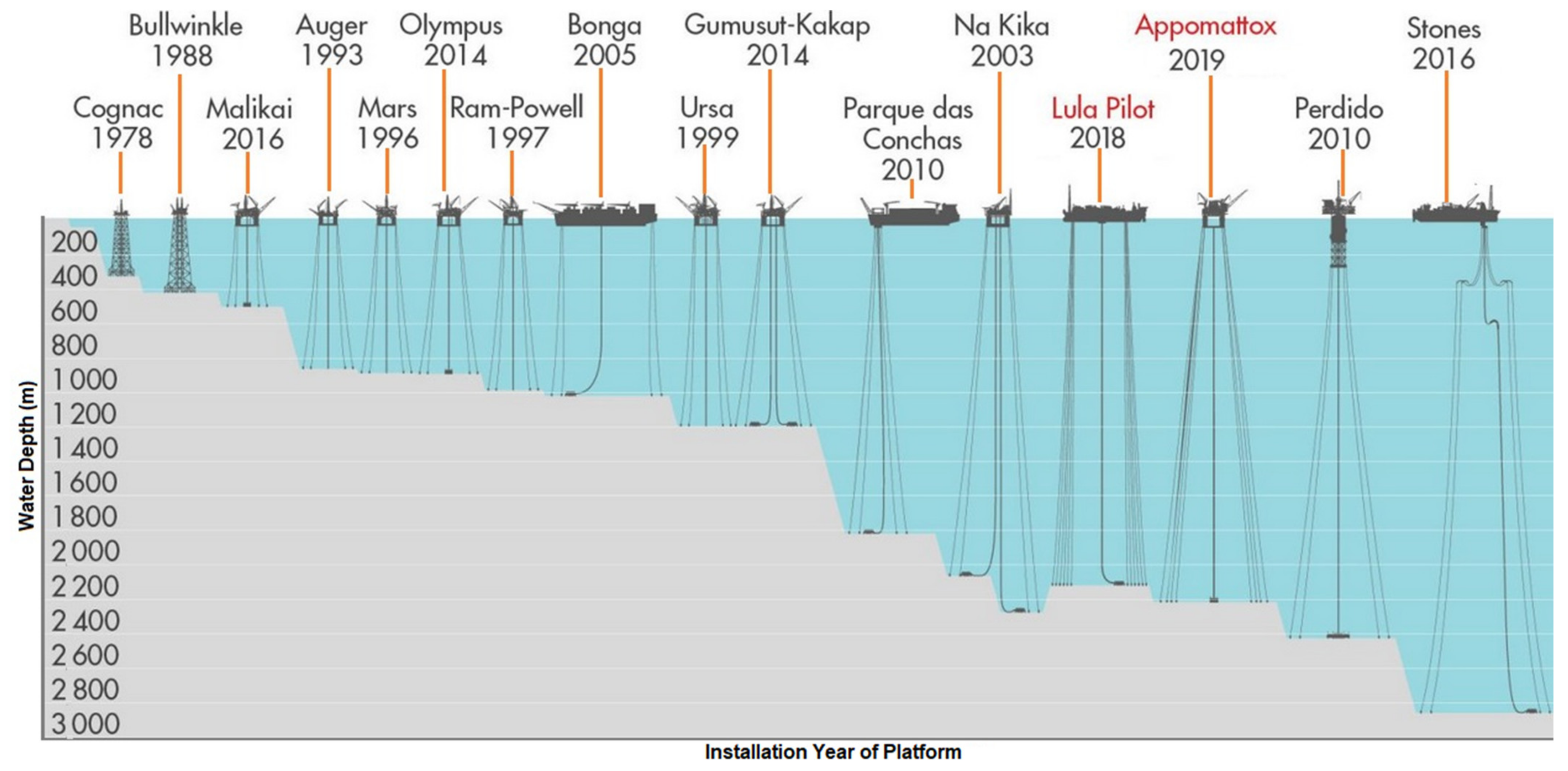
| Platforms | Sea Depths | Installed Years | Platform Type | Oil Field |
|---|---|---|---|---|
| Perdido | 2450.0 m | 2010 | SPAR | GoM |
| Thunder Horse | 1841.0 m | 2010 | SemiSubmersible | GoM |
| Magnolia | 1400.0 m | 2003 | ETLP | GoM |
| Mad dog | 1311.0 m | 2005 | SPAR | GoM |
| Bonga | 1000.0 m | 2005 | FPSO | Nigeria |
| Marlin | 988.0 m | 1999 | TLP | GoM |
| Ram-Powell | 980.0 m | 1997 | TLP | GoM |
| Olympus | 914.0 m | 2014 | TLP | GoM |
| URSA | 1204.0 m | 1999 | TLP | GoM |
| Mars | 896.0 m | 1996 | TLP | GoM |
| Auger | 872.0 m | 1993 | TLP | GoM |
| Jolliet | 536.0 m | 1989 | TLP | GoM |
| Bullwinkle | 412.0 m | 1988 | Fixed Platform | GoM |
| Appomattox | 2195.0 m | 2019 | Semisubmersible | GoM |
| Na Kika | 1829.0 m | 2003 | Semisubmersible | GoM |
| Atlantis | 2134.0 m | 2007 | Semisubmersible | GoM |
| Heidrun | 351.0 m | 1995 | TLP | GoM |
| Snorre | 310.0 m | 1992 | TLP | North Sea |
| Cognac | 304.0 m | 1978 | Fixed Platform | GoM |
| Hutton | 148.0 m | 1984 | TLP | North Sea |
| Vito | 1189.0 m | 2022 | Semisubmersible | GoM |
| Argos | 1311.0 m | 2022 | Semisubmersible | GoM |
| Parameters | Gulf of Mexico (GoM) | Africa | East Asia | Australia |
|---|---|---|---|---|
| Winds | Loop current | Seasonal winds and River flow | Monsoon and internal waves | Loop current, Monsoon and internal waves |
| Currents | Winter storms and Hurricane | Bi-modal state and Long period swells | Monsoons and Typhoons | Monsoons, Typhoons, Winter storms and Hurricane |
| Waves | Winter storms and Hurricanes | Trade winds and Squalls | Typhoons, Squalls and monsoons | Monsoons, Typhoons, Winter storms and Hurricanes |
| Types of Water Depth | Relative Depth (h/L) |
|---|---|
| Shallow Water | h/L < 0.5 |
| Intermediate Water | 0.05 < h/L < 0.5 |
| Deep Water | h/L > 0.5 |
| Name of Software | Year Founded | Type of Software and Program Specialisation | Software Company/Vendor/Manufacturer | Location |
|---|---|---|---|---|
| ANSYS Workbench | 1970 | CAE/multiphysics engineering simulation software for product design, testing and operation | ANSYS | Pennsylvania, U.S.A. |
| COMSOL Multiphysics | 1986 | cross-platform finite element analysis, solver and multiphysics simulation software | COMSOL Inc | Stockholm, Sweden |
| StruCAD | 1986 | a specialised 3D modelling package used in the structural steel industry, detailing, fabrication and information management system | STRUMIS LTD’s AceCad Software Ltd. | Derby, UK |
| ABAQUS | 1978 | finite element analysis and computer-aided engineering (CAE) | Dassault Systèmes’ SIMULIA | Vélizy-Villacoublay, France |
| Solidworks | 1981 | Design and Analysis of Structural elements (beams, columns, walls, slabs, CAD, drafting) | Dassault Systèmes | Vélizy-Villacoublay, France |
| CATIA | 1981 | Design and Analysis of Structural elements (beams, columns, walls, slabs, CAD, drafting) | Dassault Systèmes | Vélizy-Villacoublay, France |
| STAAD.Pro | 1997 | Design and Analysis of Structural elements (Foundations, beams, columns, walls, slabs) | Bentley Systems | Pennsylvania, U.S.A. |
| RAM Structural | 1984 | Design and Analysis of Structural elements (Foundations, beams, columns, walls, slabs) | Bentley Systems | Pennsylvania, U.S.A. |
| Solid Edge | 1995 | Design and Analysis of Structural elements | Siemens Digital Industries | Texas, U.S.A. |
| RISA | 1987 | Design and Analysis of Structural elements (Foundations, beams, columns, walls, slabs) | Risa Tech, Inc. | California, U.S.A. |
| ADAPT-Builder | 1983 | Design and Analysis of Structural elements (foundations, beams, columns, walls, slabs) | Risa Tech, Inc. & ADAPT Corporation | California, U.S.A. |
| SAFE | 1975 | Design and Analysis of Structural elements (beams, foundations, and slabs) | Computer and Structures, Inc. (CSI) | California, U.S.A. |
| ETABS | 1975 | Design and Analysis of Structural elements (beams, columns, walls, and slabs) | Computer and Structures, Inc. (CSI) | California, U.S.A. |
| SAP2000 | 1975 | Design and Analysis of Structural elements (beams, columns, walls, and slabs) | Computer and Structures, Inc. (CSI) | California, U.S.A. |
| Robot Structural | 1982 | Design and Analysis of Structural elements (foundations, beams, columns, walls, slabs) | Autodesk | California, U.S.A. |
| AutoCAD | 1982 | 3D Design and Analysis of Structural elements (beams Columns, walls, and Slabs) | Autodesk | California, U.S.A. |
| Autodesk Inventor | 1999 | Design and Analysis of Structural elements (beams Columns, walls, and Slabs) | Autodesk | California, U.S.A. |
| S-Frame | 1981 | 3D Structural Analysis Linear, Non-Linear, Static, Dynamic | Altair Engineering Inc.’s S-Frame | Michigan, U.S.A. |
| S-Concrete | 1981 | Design and Analysis of Structural elements (beams, columns, and walls) | Altair Engineering Inc.’s S-Frame | Michigan, U.S.A. |
| S-Steel | 1981 | Design and Analysis of Structural elements (beams, columns, and walls) | Altair Engineering Inc.’s S-Frame | Michigan, U.S.A. |
| MARC | 1971 | nonlinear FEA software used to simulate behavior of complex materials and interaction under large deformations and strains. | MSC Software Corporation | California, U.S.A. |
| MSC/Nastran | 1971 | nonlinear FEA software used to simulate behavior of complex materials and interaction under large deformations and strains. | MSC Software Corporation | California, U.S.A. |
| PROKON | 1989 | Design and Analysis of Structural elements (foundations, beams, columns, walls, slabs) | Prokon Software Consultant (Pty) Ltd. | Johannesburg, South Africa |
| PTC Creo (formerly Pro/Engineer) | 1988 | a family of Computer-aided design (CAD) apps supporting product design for discrete manufacturers, 3D/2D, FEA & simulations | PTC (Parametric Technology Corporation) | Massachusetts, U.S.A. |
| RFEM/RSTAB | 1987 | structural analysis/FEA software used to simulate behavior of materials and interaction under large deformations and strains | Dlubal Software | Philadelphia, U.S.A. |
| Name of Software | Standalone Version OS | Price | Rendering Platform | Integrations | Developer |
|---|---|---|---|---|---|
| Blender | Windows, Mac OS, Linux | Free | CPU, GPU | NA | Blender |
| Maya | Windows, macOS, Linux | Free (trial ware, academic), £1575/year | CPU, GPU | RebusFarm, Adobe Substance 3D Designer, Adobe Substance, 3D Painter, V-Ray, SyncSketch, Verge3D, Maxwell, OctaneRenderer, Houdini, Anima, Redshift, Iray. | Autodesk Inc. |
| 3ds Max | Windows | Free (academic), $1785/year, $225/m | CPU, GPU | V-Ray, Space Designer 3D, Shapespark, Verge3D, Maxwell, Corona Renderer, Houdini, Anima, Redshift, Iray | Autodesk Inc. |
| Rhino3D/Rhinoceros | Windows, macOS | $995 (€995) (single use), €595 (upgrade) | CPU | Revit | Robert McNeel & Associates |
| Lumion 3D | Windows | From $1760 | GPU | NA | Lumion |
| V-Ray | NA | From $60/month | CPU, GPU | Revit, Rhinoceros, SketchUp, Unreal, 3ds Max, Blender, Cinema 4D, Houdini, Katana, Maya, Modo, Nuke | Chaos Group |
| Keyshot | Windows, macOS | $995 | CPU, GPU (Nvidia) | Solidworks, Maya, Cinema 4D, SketchUp, Rhino | KeyShot |
| DS Solidworks Visualize | Windows | Price on request | CPU, GPU | NA | Solidworks |
| Enscape | Windows | $69.90/$478.80 per m/year | GPU | ArchiCAD, Revit, Rhinoceros, SketchUp, Vectorworks | Enscape |
| OctaneRender | NA | From $19.99/month | GPU (Nvidia) | Rhinoceros, SketchUp, Softimage, Unreal, Maya, Modo, Nuke, Poser, Revit, 3ds Max, ArchiCAD, Blender, AutoCAD, Carrara, Cinema 4D, DAZ Studio, Houdini, Inventor, Lightwave, | Octane Render |
| Corona Renderer | Windows | ~$30/month | CPU | 3ds Max, Cinema4D | Corona |
| 3Delight | Windows, macOS, Linux | Free (limited to 12 cores) $30/$60/$360 per w/m/year $720 perpetual | CPU | NA | 3Delight |
| Maxwell Render | Windows, macOS, Linux | From ~$580 (495€) | CPU, GPU (Nvidia) | Modo, Rhinoceros, SketchUp, 3ds Max, ArchiCAD, Cinema 4D, Form-Z, Maya | Maxwell |
| Thea Render | NA | ~$290 (249€)/year | CPU, GPU | Rhino, SketchUp | Thea Render |
| Cheetah 3D | macOS | Free demo, $99 (single license), $49 (upgrade) | CPU | NA | Cheetah3d |
| Artlantis | Windows, macOS | ~$910 (780€) | CPU (Network) | ArchiCAD, VectorWorks, Revit, 3ds Max, SketchUp, Rhino, MODO, Maya, formZ, Cinema 4D, AutoCAD, Arc+ | Abvent’s Artlantis |
| Clarisse | Windows, macOS, Linux | Free (educational) $59/$499 per m/year $999 perpetual | CPU, GPU | NA | Isotropix |
| Arnold | Windows, macOS, Linux | $40/$360 per m/year | CPU | NA | Arnold |
| LuxCore Render | Windows | Free | GPU | NA | LuxCoreRender |
| Redshift | Windows, macOS, Linux | From $500 | GPU (Windows/Linux—Nvidia only; macOS—M1/AMD) | 3ds Max, Cinema 4D, Houdini, Maya | Redshift |
| Marmoset Toolbag | Windows, macOS | $14.99/month $299 perpetual | GPU | NA | Marmoset Toolbag |
| RenderMan | Windows, macOS, Linux | $595 | CPU, GPU (Nvidia) | Blender, Houdini, Katana, Maya | RenderMan |
| Iray | NA | $295/year | GPU (Nvidia) | 3ds Max, Maya, Rhinoceros | Nvidia Iray |
| FluidRay | Windows, macOS | $14.99/month | CPU | NA | FluidRay |
| Guerilla | Windows, Linux | Free (single-seat, connected) From ~$2340 (2000€) | CPU | Maya | Guerilla |
| Felix | Windows | $50–$800 (credit packs); $1–900/month (subscriptions) | NA | 3ds Max, AutoCAD, Rhinoceros | Felix |
| Indigo Renderer | Windows, macOS, Linux | $835 | CPU, GPU | 3ds Max, Blender, Cinema 4D, Revit, SketchUp | Indigo Renderer |
| FormZ | Windows | $439/year, $995 perpetual | CPU, GPU | NA | AutoDesSys, Inc |
| Twinmotion | Windows | Free (trial, non = commercial, Academic), ~$584.29 (£490.80) | CPU | formZ, CItyEngine, CET, Navisworks, SketchUp, 3ds Max, BricsCAD, RIKCAD, Solidworks, Rhino, Revit, ArchiCAD, VectorWorks | Epic Games, Inc. |
| D5 Render | Windows | Free | CPU (DXR) | Blender, SketchUp, 3ds Max, Rhino, Revit, ArchiCAD, Cinema 4D | d5render |
| Name of Software | Year Founded | Type of Software and Program Specialisation | Software Company/Vendor Manufacturer | Location |
|---|---|---|---|---|
| ANSYS AQWA | 1970 | Hydrodynamic software designed for industries, like Marine and Offshore structures | ANSYS Inc. | Pennsylvania, U.S.A. |
| ABAQUS AQUA | 1978 | Hydrodynamic software designed for industries, like Marine and Offshore structures | Dassault Systèmes’ SIMULIA | Vélizy-Villacoublay, France |
| FASTRUDL/NSOTM | 1981 | finite element analysis software designed for industries, like Marine and Offshore structures | PRINCIPIA | La Ciotat, France |
| Deeplines | 1981 | finite elements method and forms an integrated software solution for installation analyses of offshore structures; Global analysis of risers, moorings and flowlines | PRINCIPIA | La Ciotat, France |
| NSO/ISYMOST | 1981 | ISYMOST (Interactive SYstem for MOdeling of STructures) manages the modeling, analysis, pre- and post-processing of structures; Frames and Finite Elements solver | PRINCIPIA | La Ciotat, France |
| Flexcom | — | offshore marine engineering simulator that for the engineering design of installations, risers, moorings, umbilicals, pipelines & FOWT. | Wood Group PLC | Aberdeen, U.K. |
| PipeLay | — | an engineering tool for pipeline installation, complex finite element analysis and post-processing, automation challenges with installation scenarios in deep and shallow water | Wood Group PLC | Aberdeen, U.K. |
| OrcaFlex | 1986 | Design, 3D modelling and dynamic analysis of offshore marine systems | ORCINA | Ulverston, U.K. |
| OrcaLay | 1998 | Design, 3D modelling and dynamic analysis of for pipelaying designs | ORCINA | Ulverston, U.K. |
| OrcaBend | 1989 | Design, 3D modelling and dynamic analysis of bend stiffener design to derive an optimum stiffener profile | ORCINA | Ulverston, U.K. |
| VIVANA | 1968 | VIV, hydrodynamic and hydrostatic analysis of offshore platforms and ships | DNV | Oslo, Norway |
| DeepC, Helica & HydroD | 1968 | hydrodynamic and hydrostatic analysis of fixed and floating structures like offshore platforms and ships | DNV | Oslo, Norway |
| Sesam | 1968 | Structural and hydrodynamics analysis, FEM for design to analysis of marine operation; interaction for hull, riser and mooring lines | DNV | Oslo, Norway |
| PIPESIM & OLGA | — | Steady-state multiphase flow simulator to overcome fluid flow challenges and optimize production | Schlumberger | Texas, U.S.A. |
| WAMIT | 1987 | WAMIT, “WaveAnalysisMIT” for computing wave loads and motions, interaction of offshore structures, vessels or other structures | WAMIT Inc. | Massachusetts, U.S.A. |
| MOSES | 1984 | Hydrodynamic software designed for industries, like Marine and Offshore structures | Bentley Systems | Pennsylvania, U.S.A. |
| RIFLEX | 1968 | Riser System Analysis Program (RIFLEX) is a tailor-made and advanced tool for static and dynamic analysis of slender marine structures | DNV | Oslo, Norway |
| ANFLEX | 1995 | an in-house nonlinear dynamic analysis of lines and risers software; for static and dynamic analysis of slender marine structures | PETROBRAS/CENPES/DIPREX/ SEDEM | Rio de Janeiro, Brazil |
| HYDPROD | 2011 | Drilling hydraulics software and the suite of drilling software to meet the challenges that operators and service companies face | Pegasus Vertex Inc. (PVI) | Texas, U.S.A. |
| ProteusDS | 2006 | in-house dynamic analysis software package; time domain solvers to model hydrodynamic response of offshore structures like FOWTs | DSA Ocean | Victoria BC, Canada |
| SeaFEM | — | seakeeping 3D multi-body radiation and diffraction simulations; a suite of tools for the computational analysis of the effect of waves, wind and currents on naval and offshore | Compass Ingeniería y Sistemas | Barcelona, Spain |
| SIMA & SIMO | — | SIMA workbench offers a complete solution for simulation and analysis of marine operations and floating systems | SINTEF | Trondheim, Norway |
| aNySIM | — | time domain solvers to simulates the motions of both stationary offshore vessels, sailing ships and offshore structures like FOWTs | MARIN | Wageningen, The Netherlands |
| HydroDyn | — | time domain solvers to model hydrodynamic response of offshore structures like FOWTs | NREL | Colorado, U.S.A. |
| 3DFloat | — | integrated wind turbine simulation software; time domain solvers to model hydrodynamic response of offshore FOWTs | IFE | Kjeller, Norway |
| BECAS | 1986 | BECAS, the BEam Cross section Analysis Software, determines cross section stiffness properties using a finite element based approach | DTU Wind Energy | Roskilde, Denmark |
| HAWC2 | 1986 | HAWC2 (Horizontal Axis Wind turbine simulation Code 2nd generation) is an aeroelastic code to model the dynamic response of offshore structures like FOWTs | DTU Wind Energy | Roskilde, Denmark |
| Name of Software | Year Founded | Type of Software and Program Specialisation | Software Company/Vendor/Manufacturer | Location |
|---|---|---|---|---|
| MathCAD | 1986 | Analysis of matrix-based problems & performing specialized mathematical tasks | Parametric Technology Corporation (PTC)’s Mathsoft | Massachusetts, U.S.A. |
| MATLAB | 1979 | Analysis of matrix-based problems & performing specialized mathematical tasks | Mathworks | Massachusetts, U.S.A. |
| Simulink | 1984 | a MATLAB-based graphical programming environment for modeling, simulating and analyzing multidomain dynamical systems | Mathworks | Massachusetts, U.S.A. |
| GNU Octave | 1993 | Analysis of matrix-based problems & performing specialized mathematical tasks | John W. Eaton et al. | Texas, U.S.A. |
| Scilab | 1990 | Analysis of matrix-based problems & performing specialized mathematical tasks | ESI Group | Rungis, France |
| Mathematica | 1988 | Analysis of matrix-based problems & performing specialized mathematical tasks | Wolfram Research | Illinois, U.S.A. |
| Maple | 1982 | Analysis of matrix-based problems & performing specialized mathematical tasks | Waterloo Maple (Maplesoft) | Ontario, Canada |
| Macsyma | 1968 | Macsyma “Project MAC’s SYmbolic MAnipulator” is a general-purpose computer algebra systems still available | Symbolics’s Macsyma, Inc | Massachusetts, USA |
| LabView | 1986 | a system-design platform and development environment for a visual programming language; for state machines and flow charts | National Instruments | Texas, U.S.A. |
| RStudio | 2011 | an integrated development environment for R, a programming language for statistical computing and graphics; free and open-source software for data science. | RStudio, PBC | Washington, U.S.A. |
| MathJax | 2009 | displays mathematical notation in web browsers, using MathML, LaTeX and ASCIIMathML markup, scans the page, and typesets the mathematical information | American Mathematical Society | Rhode Island, U.S.A. |
| SageMath | 2005 | SAGE, “System for Algebra and Geometry Experimentation” is a computer algebra system (CAS) on aspects of mathematics | Prof. William Stein et al. | Washington, U.S.A. |
| SimulationX | 2002 | CAE software to efficiently model, simulate, and analyze technical, mechanical, hydraulic, pneumatic, electrical, and combined systems | ESI Group’s ESI ITI GmbH | Rungis, France |
| SU2 (Stanford University Unstructured) Code | 2012 | suite of open-source software tools in C++ for numerical solution of partial differential equation (PDE) constraints and optimization | Dr. Francisco Palacios & Dr. Thomas D. Economon | Stanford, U.S.A. |
| Simscale | 2012 | computer-aided engineering (CAE) software-as-a-service simulation application for performance testing based on cloud computing | SimScale GmbH | Munich, Germany |
| ANSYS Fluent | 1988 | commercial Computational Fluid Dynamics (CFD) software application for performance testing | ANSYS | Pennsylvania, U.S.A. |
| STAR-CCM+ | 1980 | Computational Fluid Dynamics (CFD) software application for performance testing | Siemens Digital Industries Software | Texas, U.S.A. |
| OpenFOAM | 2004 | free, open source CFD software application for performance testing and the solution of continuum mechanics problems | ESI Group’s OpenCFD Ltd. | Rungis, France |
| Steel Grade | Strength | Application Area | Standard | Process Route |
|---|---|---|---|---|
| X52 | 350 | Structures | EN 10225 | N |
| Structures & Pipelines | EN 10225 | M | ||
| X65 | 450 | Structures | EN 10225 | Q & T |
| Pipelines | EN 10225 | M | ||
| X80 | 550 | Moorings & Structures | EN 10225 | Q & T |
| Pipelines | EN 10225 | M | ||
| 650 | Jack-ups & Moorings | EN 10225 | Q & T | |
| 750 | Jack-ups & Moorings | EN 10225 | Q & T | |
| 850 | Jack-ups & Moorings | EN 10225 | Q & T | |
| API 2MT1 | ~ | Small scale construction | API 2M | M, Q & T |
| API 2H Grade 42 | ~ | Small scale construction | API 2H | M, Q & T |
| API 2H Grade 50 | ~ | Small scale construction | API 2H | M, Q & T |
| API 2W Grade 50 | ~ | Small scale construction | API 2W | M, Q & T |
| API 2Y Grade 50 | ~ | Small scale construction | API 2Y | M, Q & T |
| S355G8+M/S355G10+M | 500/660 | construction of offshore platforms and oil rigs | EN 10225 | M |
| S420G1+M/S450G1+Q | 500/660 | construction of offshore platforms and oil rigs | EN 10225 | M, Q & T |
| S420G1+M/S450G1+Q | 500/660 | construction of offshore platforms and oil rigs | EN 10225 | M, Q & T |
| S235/S355 | 350 | Heavy steel plates for construction of offshore platform | EN10025-2 | M, Q & T |
| S355G10/S355MLO/S355NLO | 350 | construction of offshore platforms and oil rigs | EN10025-2 | M |
| ASTM A36 | 250 | Structures & Pipelines | API RP-2A | M, Q & T |
Publisher’s Note: MDPI stays neutral with regard to jurisdictional claims in published maps and institutional affiliations. |
© 2022 by the authors. Licensee MDPI, Basel, Switzerland. This article is an open access article distributed under the terms and conditions of the Creative Commons Attribution (CC BY) license (https://creativecommons.org/licenses/by/4.0/).
Share and Cite
Amaechi, C.V.; Reda, A.; Butler, H.O.; Ja’e, I.A.; An, C. Review on Fixed and Floating Offshore Structures. Part II: Sustainable Design Approaches and Project Management. J. Mar. Sci. Eng. 2022, 10, 973. https://doi.org/10.3390/jmse10070973
Amaechi CV, Reda A, Butler HO, Ja’e IA, An C. Review on Fixed and Floating Offshore Structures. Part II: Sustainable Design Approaches and Project Management. Journal of Marine Science and Engineering. 2022; 10(7):973. https://doi.org/10.3390/jmse10070973
Chicago/Turabian StyleAmaechi, Chiemela Victor, Ahmed Reda, Harrison Obed Butler, Idris Ahmed Ja’e, and Chen An. 2022. "Review on Fixed and Floating Offshore Structures. Part II: Sustainable Design Approaches and Project Management" Journal of Marine Science and Engineering 10, no. 7: 973. https://doi.org/10.3390/jmse10070973
APA StyleAmaechi, C. V., Reda, A., Butler, H. O., Ja’e, I. A., & An, C. (2022). Review on Fixed and Floating Offshore Structures. Part II: Sustainable Design Approaches and Project Management. Journal of Marine Science and Engineering, 10(7), 973. https://doi.org/10.3390/jmse10070973


