Abstract
The wireless charging system (WCS) is widely employed to solve the problem of underwater charging of autonomous underwater vehicles (AUVs). However, the AUV is prone to misalignment caused by the tidal currents, which directly leads to fluctuations in transmission efficiency and output power. For this reason, a circular-arc-type (CA-type) magnetic coupler with strong misalignment tolerance was proposed in this article. Compared with the ring-type magnetic coupler, the proposed magnetic coupler had better magnetic field convergence and lower weight. Further, the effect of dimensional parameters on the CA-type magnetic coupler performance was analyzed by ANSYS Maxwell, with which the parameters of the magnetic coupler were optimized, and its coupling coefficient could finally reach 0.671. To analyze the influence of misalignment on the CA-type magnetic coupler, EE-type and UI-type magnetic cores are compared. Within the same range of rotation misalignment [−10°, 10°] and axial misalignment [−30, 30 mm], the CA-type magnetic core has stronger misalignment adaptability, and it can achieve a stable output power of 575 W and DC-DC efficiency of 92.51% when rotational misalignment occurs. A WCS experimental prototype is built based on one of the magnetic couplers and its experimental results verify the correctness of the theoretical analysis and simulation results.
1. Introduction
An autonomous underwater vehicle (AUV) has become an essential tool to complete various marine tasks in both military and civil fields. However, the limited capacity of rechargeable batteries makes the operating time of AUVs challenging [1]. There are two solutions to the problem of AUV endurance: one is to equip the AUV with a fuel battery or nuclear battery, and the other is to charge the AUV before it runs out of power. The former scheme can effectively improve the endurance of AUV, but the fuel battery technology is not yet mature, and the cost of the nuclear battery is extremely high. Therefore, the latter scheme is more adopted. In order to reduce the production cost of AUV and the complexity of system design, rechargeable lithium batteries are considered by AUV. Traditional electric energy supply is to salvage the AUV to the ship for manual charging or wet plug-in wired charging, which greatly reduces the flexibility of the AUV and has certain potential safety problems. Currently, wireless power transfer (WPT) technology, is widely used in various fields such as underwater electric equipment [2], biomedical implants [3], electric vehicles [4], and unmanned aerial vehicles [5], which can effectively improve the convenience and safety of the charging system [6,7]. Therefore, wireless charging has outstanding advantages over other power supply modes, at present, WPT is becoming a feasible type of underwater power transfer method to solve this problem in AUV effectively [8,9].
A misalignment of the coupling device is almost inevitable due to the impact of tidal currents and marine organisms, and the instability of wireless charging between the AUV and the docking station is greatly increased. The mechanical structure can often be used to maintain the stability of the coupling device [10], but this undoubtedly increases the complexity of the overall structure of the wireless charging system (WCS). The magnetic coupler is the most important component of the WPT system, as it determines the transfer performance, such as the output power and transmission efficiency. However, the magnetic coupler is very sensitive to the relative position of the transmitter and the receiver [11,12]. When the magnetic coupling device is misaligned, its coupling coefficient and mutual inductance changes significantly, which not only affects the coupling ability of the coupling device but also affects the stability of the entire WCS. Cheng et al. proposed an embedded-type magnetic coupler, it can transfer 10 kW power with a coupling efficiency of 91% [13]. Nevertheless, the bottom of the AUV needs to be modified for the installation of the embedded-type magnetic core, and this magnetic coupler needs to maintain a fixed air gap between the AUV and the docking station to achieve stable transmission. To address the issue of magnetic coupler hull compatibility, Kan et al. proposed an arc-type magnetic coupler [14], which does not require changing the AUV shape and is done by changing the core to fit the AUV housing, but this poses the problem of ferrite material fabrication. In [15], an arc-type magnetic coupler structure is proposed for AUV underwater charging, which is made of Fe-based nanocrystalline and can easily fit the AUV surface. However, by analyzing the magnetic field distribution, it requires a larger aluminum plate to shield the AUV electromagnetic interference. Similarly, Yan et al. changed the DD coil into a curly coil structure to fit the AUV surface [16]. However, the curly coil structure will bear great pressure inside the AUV, which may change the parameters of the magnetic coupler. According to the characteristics of an EE-shaped magnetic coupler, Cai et al. designed a magnetic coupler with ε-core without changing the shape of the AUV. However, its significant disadvantage is that stable transmission power and high transmission efficiency only occur when the magnetic core is well-aligned. When the magnetic core is misaligned, the coupling coefficient of the coupling device drops rapidly, and the transmission efficiency is unstable [17]. In [18,19], a ring-type (R-type) magnetic core structure is proposed for AUV underwater charging. An R-type magnetic core device has better misalignment tolerance than the former two couplers, but its weight is higher, and the R-type ferrite material is difficult to sinter. Moreover, the high-density magnetic field is generated in the AUV with an annular magnetic coupler, causing electromagnetic interference to the surrounding instruments [20]. Tianze Kan et al. proposed a three-phase WCS based on the magnetic field distribution of the annular magnetic coupler [21], which can transmit 1.0 kW of power with 92.41% efficiency at 465 kHz. However, the occurrence of rotational misalignment has a great impact on the system.
In this paper, a magnetic coupler with stronger misalignment tolerance is presented for AUV wireless charging. Firstly, a circular-arc-type (CA-type) magnetic coupler is proposed, and the geometric parameters are optimized in Section 2. Then, the WCS using primary side series compensation and secondary side parallel compensation is introduced, which can analyze the factors affecting power transmission in Section 3. In Section 4, the effects of misalignment on the performance of the CA-type, EE-type, and UI-type magnetic coupler are compared and analyzed. In Section 5, a WCS prototype is manufactured and measured to verify the correctness of simulation results. Finally, some conclusions were deduced in Section 6.
2. Novel Magnetic Coupler Structure Design
2.1. Proposal of Magnetic Coupler
The magnetic coupler is regarded as the most important component in the WPT system, and its structure design directly determines energy transfer performance and application. At present, the common structures of magnetic couplers mainly include the tank-type, cone-type, EE-type, R-type, UI-type, etc. However, they have their own drawbacks for underwater wireless charging. Thus, a new type of coupler needs to be proposed to adapt to the AUV subsea charging environment. Unlike the power transfer in the air medium, the underwater wireless power transfer needs to consider such factors as the tightness of the device, the complexity of the marine environments, and the eddy current loss in the seawater. Therefore, before designing a magnetic coupler, it is necessary to discuss its design objectives and technical requirements [15,22,23].
- Adaptability: The performance of WPT is closely related to the air gap between the transmitter and the receiver. In general, the AUV is a torpedo-like cylinder with an arcuate surface, the shape of the magnetic coupler should be designed to adapt the AUV surface as closely as possible to reduce the distance between the transmitter and the receiver;
- Lightweight and electromagnetic compatibility: AUVs usually need to carry out long-term marine tasks. In order to achieve rapid movement in the water, it is necessary to design magnetic couplers to meet the requirements of lightweight. Mn-Zn ferrite is widely used as the core material of WPT. Although the use of ferrite increases the weight, it can reduce the number of wires used in the magnetic coupler, and the whole system does not be heavier. The effect of lightweight can be further achieved by reducing the use of ferrite core in AUV. In addition, a large number of electronic devices such as sonar, GPS, and other communication systems are assembled inside the AUV. Therefore, to ensure that wireless energy transmission can be realized without affecting the normal use of AUV, electromagnetic compatibility (EMC) should be considered in the design of the coupler;
- Misalignment tolerance: AUV is slightly misaligned during the actual underwater environment charging process, which is affected by docking accuracy and ocean current, and the AUV itself cannot correct such positional changes. Although the docking station is usually equipped with a mechanical clamping device, there is still a small range of misalignment for AUVs. Therefore, it is necessary to consider the misalignment tolerance in the coupler design process.
Combined with the above technologies and requirements of an AUV magnetic coupler, in this paper, a circular-arc-type (CA-type) magnetic coupler was proposed to facilitate better marine work. The CA-type magnetic coupler means that the transmitter’s magnetic core structure is circular, and the receiver’s magnetic core structure is an arc. It was composed of a CA-type Mn-Zn ferrite core and coil that can perfectly fit the surface of the AUV. The structure of a typical AUV and the installation position of the magnetic coupler are shown in Figure 1a. It was mainly composed of a propulsion compartment, battery compartment, and instrument compartment. The area of the internal space that can be used for wireless charging was located near the battery cabin, and the upper part of the battery cabin was used to place buoyant materials. Therefore, the receiver was installed below the battery compartment, and the transmitter was placed in the docking station, as shown in Figure 1b. After the AUV entered the docking station and reached the specified position, it charged the AUV receiver through the transmitter installed outside. The docking device with such a structure can greatly avoid the radial misalignment of the AUV during the underwater wireless charging process. The overall structure of the R-type and CA-type magnetic coupler was established in ANSYS Maxwell and shown in Figure 2. All coils were wound around the x-axis, where the coils of the R-type core and the CA-type transmitter coils were wound in a circle close to the surface of the core, while the receiving coils of the CA-type magnetic coupler were wrapped around the surface of the core and form a circular arc.
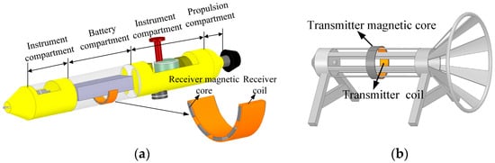
Figure 1.
Position illustrations of CA-type magnetic coupler. (a) The receiver installation on AUV. (b) The transmitter installation on the docking station.
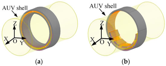
Figure 2.
Overall structure diagram of (a) R-type magnetic coupler. (b) CA-type magnetic coupler.
When the magnetic coupler structure is determined, the magnetic field strength inside the AUV needs to be further measured. It can provide guidance for the design of a magnetic coupler by judging whether it meets the requirements of magnetic compatibility. The design flow of a magnetic coupling device is shown in Figure 3.
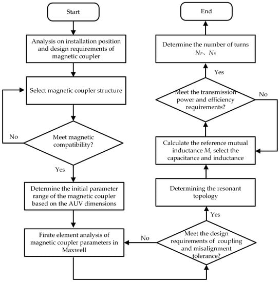
Figure 3.
Design flow of the proposed CA-type magnetic coupler for WCS.
The magnetic field was simulated in the YOZ plane and XOZ plane by Maxwell, and the calculation results of magnetic field distribution are shown in Figure 4 and Figure 5. The scales of magnetic field flux densities are the same in all figures: the maximum was 3.0969 × 10⁻³ T and the minimum was 1.0736 × 10⁻⁴ T. According to the guidelines for radiation protection of the International Commission on Nonionizing Radiation Protection (ICNRP) guidelines, the maximum value of magnetic flux density needs to be less than 20 μT [24]. As can be seen from Figure 4, the R-type magnetic coupler and the CA-type magnetic coupler had the same size. However, the magnetic field density around the receiving coil of the former was weak and the center was strong, the magnetic field around the receiving coil of the latter was strong and the center was weak. In particular, it can be seen from the scale and the values of the CA-type magnetic field intensity marking points that the flux density of the battery and electronics placed in the dashed box was less than 20 µT, which met the design requirements of the coupler. The magnetic fields in the XOZ plane can well explain why the internal magnetic field strength of the novel magnetic coupler was smaller. The magnetic field generated by the new magnetic core was more concentrated in the coil structure and less scattered around the AUV, as shown in Figure 4.
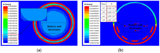
Figure 4.
Magnetic field distribution in the YOZ plane. (a) The R-type magnetic coupler. (b) The CA-type magnetic coupler.
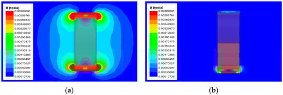
Figure 5.
Magnetic field distribution in the XOZ plane. (a) The R-type magnetic coupler. (b) The CA-type magnetic coupler.
2.2. CA-Type Magnetic Coupler Dimension Optimization
The design and optimization of magnetic coupler parameters directly affects the energy transmission performance of the WPT system. The AUV with a diameter of 300 mm was taken as the object, and the length L and thickness H of the magnetic core was limited to 300 mm. Some important designed parameters are shown in Figure 6: W is the width of the coupler transmitter and receiver, and air gap g is the vertical distance between them. The CA-type magnetic coupler was composed of multiple circular arc transmitter cores and multiple circular arc receiver cores, where θ1 represents the central angle of a single transmitter magnetic core, the central angle of a single receiver magnetic core was θ2, and the angle between the receiver core and the core was θ3. As the annular ferrite material was difficult to forge, the primary core was set as six circular arc cores with a central angle of 60°, that is, θ2 was set to 60°.
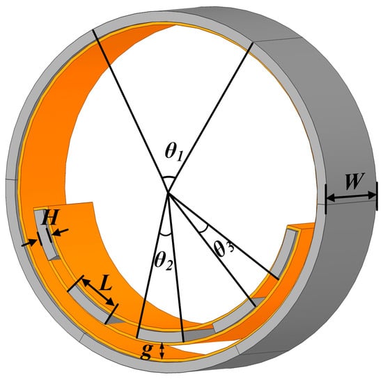
Figure 6.
Designed parameters of CA-type magnetic coupler.
Under the premise of achieving efficient energy transmission of the WPT system, the weight of AUV can be reduced by balancing the design parameters of the magnetic coupler. It means that the best value of parameters needs to be found through optimization. Due to the CA-type magnetic coupler can be well compatible with the AUV surface, the size optimization of the magnetic core includes several variables such as L, W, and H. However, it is necessary to consider the influence of rotational misalignment and axial misalignment in the process of dimension optimization. The schematic diagram of the proposed magnetic coupler rotation misalignment and axial misalignment as shown in Figure 7 and Figure 8, respectively. In general, the coupling effect of the rotational misalignment and axial misalignment of the magnetic coupler depends on the L and W of the magnetic core respectively, and the size of the L and W is closely related to the change of the coupling coefficient k in the case of misalignment.
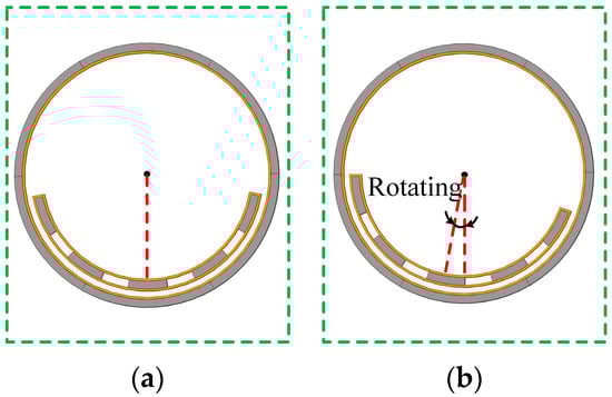
Figure 7.
Schematic diagram of misalignment of CA-type magnetic coupler in the YOZ plane. (a) Well-aligned. (b) Rotational misalignment.
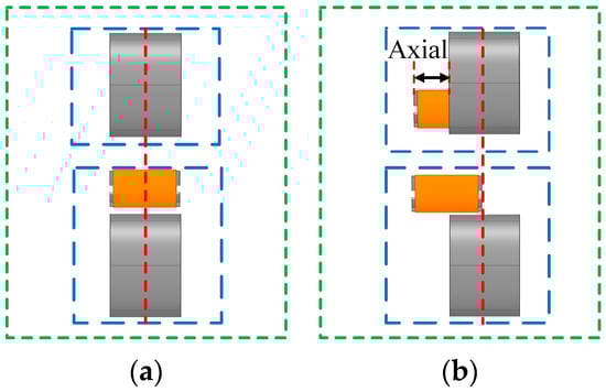
Figure 8.
Schematic diagram of misalignment of CA-type magnetic coupler in the XOZ plane. (a) Well-aligned. (b) Axial misalignment.
The forging of the magnetic core needs to be based on the actual ferrite material data and manufacturing technology. Therefore, the L and W of a single magnetic core are respectively set to vary from 30 to 70 mm and 60 to 100 mm during the optimization process. Figure 9a indicates the effect of L on k with different rotational degrees. The result shows that k increased from 0.62 to 0.7 during the increase in L from 30 to 70 mm. With the increase in the L of the secondary core, the curve about k shows an upward trend, but when the L is greater than 50 mm, the upward range decreases. In addition, the value of k of the corresponding curve does not change significantly with the increase in the rotating degree under various L values. To balance charging reliability and the weight of the magnetic coupler, 50 mm is selected as L, which is a relatively modest size and insensitive to rotation misalignment.
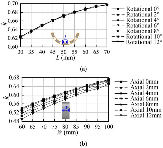
Figure 9.
k variation with (a) L. (b) W.
Different from the effect of L on the k, the increasing trend of k mainly depends on the W of the CA-type magnetic coupler. As shown in Figure 9b, as the W increases from 60 mm to 100 mm, k increases from 0.53 to 0.67, and the influence of axial misalignment on k becomes smaller, that is, increasing the W decreases the sensibility of the CA-type magnetic coupler to axial misalignment. In particular, the difference between the maximum and minimum of k declined from 0.05 to 0.02 with the axial misalignment distance increased. When the W is 100 mm, the k drops by 0.005 for every axial misalignment of 2 mm, and the parameter fluctuation is small. Therefore, the W is selected to be 100 mm.
Considering the manufacturing technology and the weight of the magnetic core, the H of the magnetic core needs to select appropriate parameters. Therefore, the H optimization range of the magnetic core is between 4 and 16. By changing the H, the variation of the k is measured as shown in Figure 10. The results show that although each curve had an increasing trend, the influence of the increase in the H on k was comparatively small compared with the influence of W on k. For the same axial misalignments, the change of k with the change of H was at most 0.05, which indicates that the sensitivity to axial misalignment was almost independent of H. Finally, the H was chosen as 10 mm.
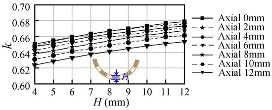
Figure 10.
k variation with H.
When the length L, width W, and thickness H of the CA-type magnetic core are determined, the influence of the number and distribution mode of the receiver magnetic core on k are investigated, and the results are shown in Figure 11. It can be seen that when the number of receiver cores Nr was the same, k can be increased by increasing θ3. This was because the increase in θ3 corresponds to an increase in the area of the coil magnetic field received. However, increasing Nr can greatly increase k compared with the increase in θ3, but excessive Nr increases the load of AUV and shorten the underwater working time. Considering the limit of the lightweight design requirements of the magnetic coupler, the number of receiver magnetic cores Nr was set to 5. In addition, the angle between the receiver cores θ3 was set to 14° to ensure the coupling capacity. Combined with the coupler design objectives and technical requirements, the perfectly magnetic coupler sizes were obtained through finite element analysis. The optimized parameters of the transmitter and receiver of the CA-type magnetic coupler are shown in Table 1.
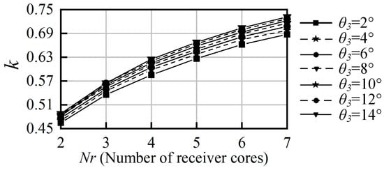
Figure 11.
k variation with Nr and θ3.

Table 1.
Parameters of CA-type magnetic coupler.
3. Theoretical Analysis of Wireless Charging System
Compared with the transformer, the coupler had the problems of large leakage inductance and low transmission efficiency due to the large air gap between coils. A resonant compensation network was formed by adding capacitance compensation to reduce the reactive power of the system and improve the transmission efficiency in the WCS. The common compensation methods are series, parallel, and LCL [25,26,27]. During the charging process, the equivalent load of WCS changes under different charging power, which will cause the output voltage of WCS to change. The resonant capacitors of SS and SP topologies are load independent and can effectively adapt to load changes. However, it is difficult to find a frequency range with good load adaptability for SS topology. Therefore, in order to illustrate the power and efficiency theoretical analysis process, a WCS with a series-parallel (SP) compensation structure is considered [19]. A topology of the WCS based on the coupling model is shown in Figure 12, it consists of two independent parts named the primary side and the secondary side. On the primary side, Udc is the DC input power supply, the H-bridge inverter is composed of four full-controlled switches S1–S4 for generating high-frequency AC power, whereas CP and CS are compensation capacitors of the transmitter and receiver respectively. On the secondary side, an H-bridge rectifier consisting of four diodes D1–D4 and capacitive filter Cdc is used to supply dc power to the load RL.
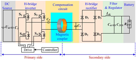
Figure 12.
Topology of SP type WCS.
Figure 13 shows the equivalent circuit model of the WCS with SP compensation. Uin is the output voltage of the inverter. IP and IS are the currents of the primary side and secondary side, respectively. L1 and L2 are respectively the self-inductances of primary and secondary. M is the mutual inductance of the transmitter and receiver. Req is the equivalent resistance of the rectifier bridge, filter circuit, and load. For the convenience of system analysis, the following parameters were analyzed based on the WCS operating at the resonance frequency ω.
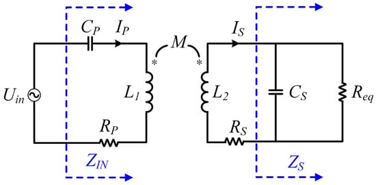
Figure 13.
Equivalent circuit of SP type WCS.
According to the voltage and current equations, the primary current IP and secondary current IS in the resonance state are obtained by:
where Z1 is the reflected impedance of the transmitter, and ZS is the input impedance of the secondary side. In this system, the output impedance ZIN of the inverter and input impedance ZS is given by:
where RP and RS are the parasitic resistance of L1 and L2, respectively. According to the calculations in the paper [28], the equivalent resistance Req can be expressed as:
Z2 is reflected impedance at the receiver, and R2 and X2 are the real part and the imaginary part of Z2. Z2, R2, and X2 can be represented by the following:
The reflection impedance at the transmitter, as well as its real and imaginary parts, can be written as:
Combining (1) to (5), the current IR on load can be solved as:
The circuit operates in a resonant state when the above formula , the compensation capacitor CS can be written as [29]:
However, the compensation capacitance CP of the transmitter is not only related to the resonance frequency ω and inductance L1 of the transmitter itself but also related to the k [30].
In the WCS, the and Equation (8) can be solved as:
Here, parasitic resistances RP and RS are not ignored, the output power Pout and transmission efficiency η of the wireless power transfer system can be expressed as:
where “Y” and “Z” are defined variables to simplify (10), Y represents and Z represents .
From the above analysis, it can be seen that there are many variables that affect the output power and transmission efficiency of the WCS, such as resonance frequency, inductance, capacitance, equivalent resistance, and so on. However, when the WCS is determined, the frequency and circuit parameters are determined as constants, and (10) can be regarded as an equation about M. For the underwater environment, M usually changes due to docking misalignment when the system is disturbed, resulting in the system losing stability. Therefore, the misalignment tolerance of magnetic couplers is a very important feature that determines whether they are widely used.
4. Finite Element Analysis for Misalignment Tolerance of Magnetic Coupler
4.1. Influence of Misalignment on Mutual Inductance and Coupling Coefficient
Misalignment of the magnetic coupler is inevitable when the AUV is docked and charged, there are generally three types of misalignments, namely rotational misalignment, axial misalignment, and radial misalignment. Considering that the AUV will be fixed by the clamping device when it enters the seabed charging dock, there are a few cases of radial misalignment. Therefore, this paper focuses on the impact of the other two misalignment cases. Generally, the recharging docks are placed at a position where the ocean currents are relatively gentle. In addition, the AUV has a certain self-stabilizing mechanism, so that the AUV will not have a large-scale rotational misalignment and axial misalignment. So, the process of finite element analysis is carried out with the rotational misalignment from −10° to 10° and the axial misalignment from −30 to 30 mm, which is based on the optimization parameters in Table 1.
Figure 14 shows a magnetic field nephogram with different rotational misalignments. The change of the magnetic field nephogram shows the change of the magnetic field between the transmitter and the receiver during the occurrence of rotational misalignment. Similar to the alignment, the change of the magnetic field is not significant when the CA-type magnetic core is rotated out of alignment. The magnetic field nephogram when the axial misalignment occurs, as shown in Figure 15. It can be seen that the magnetic field between the transmitter and the receiver is more divergent when misalignment occurs, especially when the axial misalignment is 30 mm, compared with the transmitter and the receiver alignment.
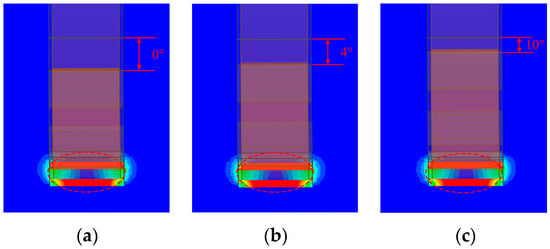
Figure 14.
Magnetic field nephogram: (a) 0° rotational misalignment; (b) 4° rotational misalignment; (c) 10° rotational misalignment.
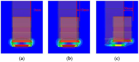
Figure 15.
Magnetic field nephogram: (a) 0 mm axial misalignment; (b) 10 mm axial misalignment; (c) 30 mm axial misalignment.
In order to further illustrate the influence of misalignment on the coupler, EE-type and UI-type cores are added to the comparison of the CA-type core. Figure 16a,b show the structures of the EE-type and UI-type cores in Maxwell, respectively. To be fair, the distance is set to be the same value between the transmitters and receivers of the three core structures. In addition, according to the analysis in Section 3, mutual inductance M has a great impact on the performance of the WCS. In order to compare the impact of dislocation on M under different structures, the mutual inductance of CA-type, EE-type, and UI-type magnetic couplers are set to similar values for a fairer comparison. The simulation parameters of the magnetic coupler are given in Table 2.
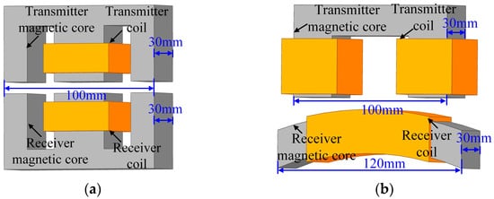
Figure 16.
The magnetic coupler with (a) EE-type. (b) UI-type.
Table 2.
Comparison of simulation parameters of the magnetic coupler.
Figure 17 shows the variation of M and k with rotation misalignment. The variation shows that the proposed CA-type magnetic coupler exhibits strong stability within the range of rotation angles [−10°, 10°], in the process of rotation dislocation, the difference between the maximum and the minimum of k is less than 0.002, corresponding to that the magnetic field has no significant change when the misalignment occurs in Figure 14. However, similar to the UI-type magnetic core, the M and k of the EE-type also show a significant downward trend with the change of misalignment, and the difference between the maximum and minimum of M is 13 μH, accounting for 25% of the overall. Although M decreases for both EE-type and UI-type cores, the latter is less variable and more stable than the former, the change is only 10 μH, accounting for about 19% of the overall.
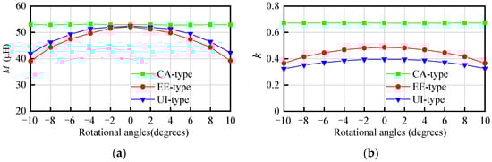
Figure 17.
Comparison of CA-type, EE-type, and UI-type magnetic couplers under rotational misalignment for (a) M. (b) k.
The variation of M and k with axial misalignment is shown in Figure 18. Compared with the effect of rotation misalignment on k and M, the declining trend of axial misalignment is more obvious. Although each curve shows a decreasing trend with the increase in axial offset, the slope of each curve is not identical. The decline amplitude of M of UI-type magnetic coupler with axial misalignment is less than EE-type, the former variation is 36% as axial misalignment from 0 to 30 mm, and the latter variation is 48%. However, the tolerance of CA-type core misalignment is better than the first two. When the axial distance is increased from 0 to 30 mm, the M is decline from 52 to 37 μH and its variation is 29%. In addition, the k declined from 0.67 to 0.55 and its variation is 18%. This result is closely related to the relative divergence of the magnetic field when the offset is 30 mm in Figure 15.
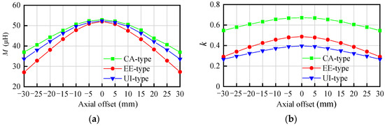
Figure 18.
Comparison of CA-type, EE-type, and UI-type magnetic couplers under axial misalignment for (a) M. (b) k.
4.2. Influence of Docking Misalignment on Transmission Efficiency and Output Power
According to the above analysis, misalignments will change the value of mutual inductance M and coupling coefficient k. However, the variation of M and k will directly affect the DC-DC transmission efficiency η and output power Pout. To analyze the effect of misalignment on η and Pout, the WCS with SP compensation was built based on the parameters of the couplers in Table 2, and the other parameters of the system are shown in Table 3.
Table 3.
Comparison of WCS parameters.
The system is connected with the same voltage and load for a fair comparison, the analysis results are shown in Figure 19 and Figure 20. From Figure 19a, it can be seen that the η of the EE-type magnetic coupler decreases obviously with the increase in the rotation angle, and the UI-type magnetic core decreases slightly. However, the CA-type magnetic core is little affected by the rotation misalignment, and the efficiency is basically stable at 92.51%. The variation of Pout is shown in Figure 19b, when the rotation angle changes from −6° to 6°, the Pout of the EE-type and UI-type magnetic core shows a significant upward trend. However, the Pout of the EE-type magnetic core gradually decreases when the rotational angle is greater than 6° (which ranges from −10° to −6° and 6° to 10°), while the Pout of the UI-type magnetic coupler is a continuation of the uptrend. This phenomenon is mainly due to the fact that the relationship between Pout and M is not monotonic according to Equation (10). To facilitate the analysis, we can take the mutual inductance corresponding to the maximum efficiency as Mmax, and when M < Mmax, the power increases at first and then decreases as M decreases. Different from the former two, the CA-type magnetic coupler kept stable at about 575 W throughout the process.
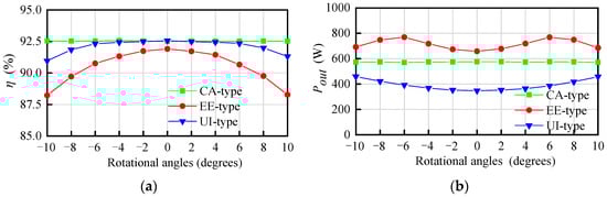
Figure 19.
Comparison of CA-type, EE-type, and UI-type magnetic couplers under rotational misalignment for (a) η. (b) Pout.
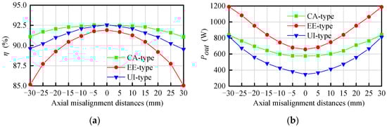
Figure 20.
Comparison of CA-type, EE-type, and UI-type magnetic couplers under axial misalignment for (a) η. (b) Pout.
In the same way, the axial misalignment distances are changed only in 5 mm steps with other conditions fixed, the variation of the η is shown in Figure 20a. It is shown that each curve has a decreasing trend, and the slope of the curve increases with the increase in the axial misalignment distance. Compare with the effect of rotational angles on the η, the declining trend of η is more obvious. When the distance is increased from 0 mm to 30 mm, the η of EE-type declined from 92% to 85%. While the CA-type magnetic coupler is more stable, the variation is only 1.5%. In addition, the output power Pout is also greatly affected by the axial misalignment. As shown in Figure 20b, for three different types of magnetic couplers, the Pout of the WCS with SP compensation structure also increases with the axial misalignment distance increases. When the distance is increased from 0 to 30 mm, the Pout of the WPT system with EE-type magnetic coupler can reach more than 650 W, the Pout of CA-type can reach more than 550 W, and the UI-type can reach more than 350 W.
4.3. Compared with Previous Research on Magnetic Coupler of AUV WCS
In recent years, different types of magnetic couplers have been proposed. In order to meet the design requirements of AUV magnetic couplers, easy forging and mounting, shape adaptability, receiver weight, coupling coefficient, and resistance to misalignment, should be taken as indicators for consideration. In addition, the different operating environments and compensation structures of wireless charging systems can also have a significant impact on the system. Therefore, the operating frequency, system compensation structure, transmission power, and transmission efficiency also need to be considered. The magnetic coupler proposed in this paper is compared with the previously proposed magnetic coupler as shown in Table 4. It can be seen that the proposed CA-type magnetic coupling device has more AUV surface adaptability in shape than the cone-type magnetic coupler, stronger dislocation tolerance than the dipole arc-type magnetic coupler, the lighter weight of receiver than the H-type, R-type, and three-phase R-type magnetic couplers, and easier forging. While the transmission performance is excellent under the same topology. In conclusion, the scheme proposed in this paper has the characteristics of high practicality and good application prospect.
Table 4.
Comparison with previous AUV WCS. (A higher “★” represent better performance on this item, “★★★★★” means the best).
5. Experimental Verification
In order to verify the correctness of the theoretical analysis and simulation results, an experimental prototype for the wireless power transfer system with SP compensation is built based on the EE-type magnetic coupler, as shown in Figure 21. It contains a DC power supply, drive circuit power supply, oscilloscope, power analyzer, DSP control circuit, drive circuit, inverter circuit, magnetic coupler, rectification circuit, and load. DSP control chip adopts microcontroller TMS320F28335, which can generate a 4-channel PWM signal to control the drive circuit, thus driving the SiC MOSFETs in the H-bridge inverter. The drive circuit power supply is employed to supply power to the drive circuit. The oscilloscope is used to capture the voltage waveforms at the primary and secondary sides of the magnetic coupler. The power analyzer is used to measure the system output power and transmission efficiency during the charging. The power supply Udc is constant at about 80 V, and the load RL is set at 20 Ω. In addition, the alternating magnetic field forms eddy current loss in seawater, and the eddy current loss is directly correlated to the frequency [33]. However, the eddy current loss is very small at the resonance frequency of 50 kHz, which can be considered that the system performance in the seawater environment is basically the same as the air. Therefore, the working frequency f of 50 kHz is selected in this paper. The specific parameters of the system are shown in Table 5.
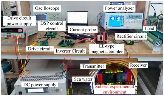
Figure 21.
Experimental prototype of wireless charging system with EE-type magnetic coupler.
Table 5.
Parameters of EE-core wireless transmission system.
Figure 22 shows the oscilloscope waveforms of primary side voltage UP and secondary side voltage US at aligned. It can be seen from the waveform that the primary and secondary sides are well coupled, and the energy can be transferred to the secondary side smoothly, which is consistent with the results of the simulation analysis. To test the difference between the ideal working environment and the actual working environment, the EE-type magnetic coupler was placed in air and seawater environments with 3.5% salt. As there is no insulating layer outside the Litz wires, the BVR cables with insulating material are used for the couplers’ windings in the seawater experiment. The transmission efficiency η and the output power Pout results of the power analyzer are shown in Figure 23. As shown in Figure 23a, when the transmitter of the magnetic coupler is fully aligned with the receiver in air condition, the η is 87.978% and the Pout is 627.2 W. The η and the Pout of the WPT system at aligned are respectively 85.843% and 618.5 W in seawater condition, as is shown in Figure 23b. It shows that the transmission efficiency and power of seawater are slightly lower than that of air. The low transmission efficiency is because the additional eddy current losses caused by electromagnetic field passing through the seawater, while the change of transmission power is mainly due to the BVR wire resistance is larger than the Litz wires.
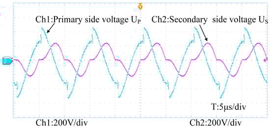
Figure 22.
The voltage waveform of primary and secondary sides with magnetic coupler.
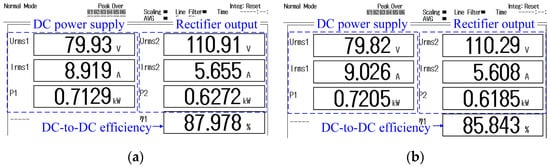
Figure 23.
Output power and transmission efficiency parameters of power analyzer in (a) air condition. (b) seawater condition.
To evaluate the stability of system energy transmission, the variation of the η and Pout with axial misalignment is measured in air and seawater conditions, and compared with the simulation results in Figure 20. The comparison results as shown in Figure 24a,b. The results show that there are other losses during the experiment, resulting in the experimental value being slightly smaller than the simulation value, but their change trends are consistent. Within the misalignment range of −30–30 mm, the deviation between the air experimental value and the simulation value is about 4%, while the seawater measurement value of η is around 2% smaller than the air measurement value. The main reason for the experimental and simulation error is that the winding process of the coil is uneven, and the simulation and calculation assume that the coil is uniformly close to the magnetic coupler. Therefore, these values indicate that the measurement results and simulation results, in the range of allowable error, are basically in agreement, which can well verify the correctness of the simulation in Figure 20. In other words, the experiment also confirms the superior performance of the proposed CA-type magnetic coupler.
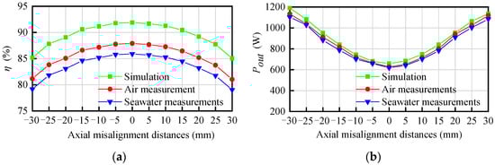
Figure 24.
Compare the results of simulation, air measurement, and seawater measurement for (a) η. (b) Pout.
6. Conclusions
In this paper, a circular-arc-type (CA-type) magnetic coupler for AUV wireless charging system is proposed. The proposed structure realizes lighter weight and better magnetic field convergence than the ring-type (R-type) magnetic coupler. The transmitter and receiver are also optimized with simulation, the simulation results show that the CA-type magnetic coupler is capable of transmitting 575 W with a DC-DC efficiency of 92.51% in the fully alignment, and has less k fluctuation and more stable transmission performance with the same misalignment compared with the EE-type and UI-type magnetic coupler. To verify the correctness of the simulation results, the WCS prototype is built and analyzed based on EE-type magnetic coupler, which is one of the three contrastive magnetic couplers, in air and sea conditions. The experimental results show that the transmission efficiency is 87.978% and the output power is 627.2 W when the transmitter and receiver are aligned in the air, and it can transmit 618.5 W power at a DC-DC efficiency of 85.843% in seawater, which is basically consistent with the simulation results. This CA-type magnetic coupler provides a feasible scheme for electric equipment with an arc shell to realize WPT. It should be noted that the application context of the CA-type magnetic coupler in this paper is AUV wireless charging, so only the effect of axial misalignment on the transmission characteristics of the system is considered. However, the structure may have radial misalignment when applied to other backgrounds, which may have an effect on M as well as k, and further studies are needed.
Author Contributions
Conceptualization, methodology, and writing—original draft preparation, T.X. and H.L.; writing—review and editing, T.X., H.L. and Y.Z.; supervision, H.Y. and P.H. All authors have read and agreed to the published version of the manuscript.
Funding
This research was funded by the National Natural Science Foundation of China under Grants 41576096 and 41876096, Youth Fund of Jiangsu Natural Science Foundation under·BK20201034, Jiangsu Distribution Network Intelligent Technology and Equipment Collaborative Innovation Center under XTCX202002, Natural Science Research Project of Jiangsu Higher Education Institutions under Grant 20KJB470028 and Scientific Research Fund of Nanjing Institute of Technology (YKJ2019115).
Institutional Review Board Statement
Not applicable.
Informed Consent Statement
Not applicable.
Data Availability Statement
Not applicable.
Conflicts of Interest
The authors declare no conflict of interest.
References
- Page, B.R.; Mahmoudian, N. Simulation-Driven Optimization of Underwater Docking Station Design. IEEE J. Ocean. Eng. 2020, 45, 404–413. [Google Scholar] [CrossRef]
- Wu, X.; Sun, P.; Yang, S.; He, L.; Cai, J. Review on Underwater Wireless Power Transfer Technology and Its Application. Trans. China Electrotech. Soc. 2019, 34, 1559–1568. [Google Scholar]
- Tamura, M.; Murai, K.; Matsumoto, M. Design of disposable film-type capacitive wireless charging for implantable medical devices. In Proceedings of the 2021 IEEE MTT-S International Microwave Symposium (IMS), Atlanta, GA, USA, 7–25 June 2021; pp. 58–61. [Google Scholar]
- Akhil, A.G.; Harisankar, S.; Jishnu, K.; Sreenand, S.; Vijay, V.; Asha, C.A.; Preetha, P.K. Coupled Wireless Charging system for Electric Vehicles. In Proceedings of the 2021 Third International Conference on Intelligent Communication Technologies and Virtual Mobile Networks (ICICV), Tirunelveli, India, 4–6 February 2021; pp. 475–479. [Google Scholar]
- Campi, T.; Cruciani, S.; Maradei, F.; Feliziani, M. Wireless charging system integrated in a small unmanned aerial vehicle (UAV) with high tolerance to planar coil misalignment. In Proceedings of the EMC Sapporo/APEMC, Sapporo, Japan, 3–7 June 2019; pp. 601–604. [Google Scholar]
- Zhao, Z.; Zhang, Y.; Chen, K. New Progress of Magnetically-coupled Resonant Wireless Power Transfer Technology. Proc. Chin. Soc. Electr. Eng. 2013, 33, 1–13. [Google Scholar]
- Park, C.; Lee, S.; Jeong, S.Y.; Cho, G.; Rim, C.T. Uniform Power I Type Inductive Power Transfer System With DQ-Power Supply Rails for On-Line Electric Vehicles. IEEE Trans. Power Electron. 2015, 30, 6446–6455. [Google Scholar] [CrossRef]
- Zhang, X.; Wang, Z.; Wei, B.; Wang, S.; Yang, Q. Analysis of the Influence of Electric Shield on Space Magnetic Field in Electric Vehicle Wireless Charging System. Trans. China Electrotech. Soc. 2019, 34, 1580–1588. [Google Scholar]
- Azad, A.; Tavakoli, R.; Pratik, U.; Varghese, B.; Coopmans, C.; Pantic, Z. A Smart Autonomous WPT System for Electric Wheelchair Applications with Free-Positioning Charging Feature. IEEE J. Emerg. Sel. Top. Power Electron. 2020, 8, 3516–3532. [Google Scholar] [CrossRef]
- Barzegaran, M.R.; Zargarzadeh, H.; Mohammed, O.A. Wireless Power Transfer for Electric Vehicle Using an Adaptive Robot. IEEE Trans. Magn. 2017, 53, 7205404. [Google Scholar] [CrossRef]
- Zhang, W.; Mi, C.C. Compensation Topologies of High-Power Wireless Power Transfer Systems. IEEE Trans. Veh. Technol. 2016, 65, 4768–4778. [Google Scholar] [CrossRef]
- Kamineni, A.; Neath, M.J.; Covic, G.A.; Boys, J.T. A Mistuning-Tolerant and Controllable Power Supply for Roadway Wireless Power Systems. IEEE Trans. Power Electron. 2017, 32, 6689–6699. [Google Scholar] [CrossRef]
- Cheng, Z.; Lei, Y.; Song, K.; Zhu, C. Design and loss analysis of loosely coupled transformer for an underwater high-power inductive power transfer system. IEEE Trans. Magn. 2015, 51, 8401110. [Google Scholar]
- Kan, T.; Zhang, Y.; Yan, Z.; Mercier, P.P.; Mi, C.C. A rotation-resilient wireless charging system for lightweight autonomous underwater vehicles. IEEE Trans. Veh. Technol. 2018, 67, 6935–6942. [Google Scholar] [CrossRef]
- Wang, D.; Cui, S.; Zhang, J.; Bie, Z.; Song, K.; Zhu, C. A Novel Arc-Shaped Lightweight Magnetic Coupler for AUV Wireless Power Transfer. IEEE Trans. Ind. Appl. 2022, 58, 1315–1329. [Google Scholar] [CrossRef]
- Yan, Z.; Zhang, Y.; Zhang, K.; Song, B.; Mi, C. Underwater wireless power transfer system with a curly coil structure for AUVs. IET Power Electron. 2019, 12, 2559–2565. [Google Scholar] [CrossRef]
- Cai, C.; Qin, M.; Wu, S.; Yang, Z. A strong misalignment tolerance magnetic coupler for autonomous underwater vehicle wireless power transfer system. In Proceedings of the 2018 IEEE International Power Electronics and Application Conference and Exposition, Shenzhen, China, 4–7 November 2018; pp. 1–5. [Google Scholar]
- Shi, J.; Li, D.; Yang, C. Design and analysis of an underwater inductive coupling power transfer system for autonomous underwater vehicle docking applications. J. Zhejiang Univ. Sci. C 2014, 15, 51–62. [Google Scholar] [CrossRef]
- Lin, M.; Li, D.; Yang, C. Design of an ICPT system for battery charging applied to underwater docking systems. Ocean. Eng. 2017, 145, 373–381. [Google Scholar] [CrossRef]
- Cai, C.; Zhang, Y.; Wu, S.; Liu, J.; Zhang, Z.; Jiang, L. A circumferential coupled dipole-coil magnetic coupler for autonomous underwater vehicles wireless harging applications. IEEE Access 2020, 8, 65432–65442. [Google Scholar] [CrossRef]
- Kan, T.; Mai, R.; Mercier, P.P.; Mi, C.C. Design and analysis of a three-phase wireless charging system for lightweight autonomous underwater vehicles. IEEE Trans. Power Electron. 2018, 33, 6622–6632. [Google Scholar] [CrossRef]
- Wu, S.; Cai, C.; Wang, A.; Qin, Z.; Yang, S. Design and Implementation of a Uniform Power and Stable Efficiency Wireless Charging System for Autonomous Underwater Vehicles. IEEE Trans. Ind. Electron. 2022, 99, 1–10. [Google Scholar] [CrossRef]
- Cai, C.; Wu, S.; Zhang, Z.; Jiang, L.; Yang, S. Development of a Fit-to-Surface and Lightweight Magnetic Coupler for Autonomous Underwater Vehicle Wireless Charging Systems. IEEE Trans. Power Electron. 2021, 36, 9927–9940. [Google Scholar] [CrossRef]
- Budhia, M.; Covic, G.A.; Boys, J.T. Design and optimization of circular magnetic structures for lumped inductive power transfer systems. IEEE Trans. Power Electron. 2011, 26, 3096–3108. [Google Scholar] [CrossRef]
- Song, K.; Li, Z.; Jiang, J.; Zhu, C. Constant Current/Voltage Charging Operation for Series-Series and Series-Parallel Compensated Wireless Power Transfer Systems Employing Primary-Side Controller. IEEE Trans. Power Electron. 2018, 33, 8065–8080. [Google Scholar] [CrossRef]
- Alkasir, A.; Abdollahi, S.E.; Abdollahi, S.R.; Wheeler, P. A Primary Side CCS-MPC Controller for Constant Current/Voltage Charging Operation of Series-Series Compensated Wireless Power Transfer Systems. In Proceedings of the 2021 12th Power Electronics, Drive Systems, and Technologies Conference (PEDSTC), Tabriz, Iran, 2–4 February 2021; pp. 1–5. [Google Scholar]
- Dongming, G.; Dangshu, W. Research on Transmission Characteristics of Dual LCL Resonance Compensation Topology in Wireless Charging System. In Proceedings of the 2021 IEEE 5th Information Technology, Networking, Electronic and Automation Control Conference (ITNEC), Xi’an, China, 15–17 October 2021; pp. 185–189. [Google Scholar]
- Li, Z.; Zhu, C.; Jiang, J.; Song, K.; Wei, G. A 3-kW Wireless Power Transfer System for Sightseeing Car Supercapacitor Charge. IEEE Trans. Power Electron. 2017, 32, 3301–3316. [Google Scholar] [CrossRef]
- Yan, Z.; Zhang, Y.; Song, B.; Zhang, K.; Kan, T.; Mi, C. An LCC-P compensated wireless power transfer system with a constant current output and reduced receiver size. Energies 2019, 12, 172. [Google Scholar] [CrossRef]
- Wang, Y.; Mai, J.; Yao, Y.; Xu, D. Analysis and Design of an IPT System Based on S/SP Compensation with Improved Output Voltage Regulation. IEEE Trans. Ind. Inform. 2020, 16, 3256–3266. [Google Scholar] [CrossRef]
- Qiao, K.; Sun, P.; Rong, E.; Sun, J.; Zhou, H.; Wu, X. Anti-misalignment and lightweight magnetic coupler with H-shaped receiver structure for AUV wireless power transfer. IET Power Electron. 2022, 15, 1843–1857. [Google Scholar] [CrossRef]
- Kojiya, T.; Sato, F.; Matsuki, H.; Sato, T. Automatic power supply system to underwater vehicles utilizing non-contacting technology. In Proceedings of the Oceans MTS/IEEE Techno-Ocean, Kobe, Japan, 9–12 November 2004; Volume 4, pp. 2341–2345. [Google Scholar]
- Yan, Z.; Zhang, Y.; Kan, T.; Lu, F.; Zhang, K.; Song, B.; Mi, C.C. Frequency optimization of a loosely coupled underwater wireless power transfer system considering eddy current loss. IEEE Trans. Ind. Electron. 2019, 66, 3468–3476. [Google Scholar] [CrossRef]


Disclaimer/Publisher’s Note: The statements, opinions and data contained in all publications are solely those of the individual author(s) and contributor(s) and not of MDPI and/or the editor(s). MDPI and/or the editor(s) disclaim responsibility for any injury to people or property resulting from any ideas, methods, instructions or products referred to in the content. |
© 2023 by the authors. Licensee MDPI, Basel, Switzerland. This article is an open access article distributed under the terms and conditions of the Creative Commons Attribution (CC BY) license (https://creativecommons.org/licenses/by/4.0/).