Abstract
Improving the produced fluid yield is an effective measure for realizing the crude oil production capacity of offshore platforms. However, for offshore platforms employed in production, using the narrow space of the platform to expand the produced water treatment system is a significant problem. In this study, a highly efficient pre-treatment core tube was coupled with the main cavity and secondary cavities (MCSCs) based on a vane-type tubular separator and a cub-mother cyclone. The optimal inlet Reynolds number and processing capacity were determined according to the structure size of the MCSC, and the MCSC was applied to achieve highly efficient pre-treatment of produced water in a heavy oilfield in the Bohai Sea. The comprehensive evaluation indicators FA and FV were better than those used by current technology. When the influent oil content fluctuated around 2000 mg/L (average of 1772.81 mg/L), the oil content in the effluent was stable and below 200 mg/L (average of 106.44 mg/L), and the separation efficiency was nearly 94%. Compared to those of the current corrugated plate interceptor on the platform, the floor space was reduced by more than 60% and the separation efficiency increased by up to 65%.
1. Introduction
China is the world’s largest importer of crude oil and natural gas [1]. In 2021, external dependence on crude oil showed a downward trend for the first time in nearly 20 years, but it was still as high as 72%. However, the challenge of energy security still exists [2,3]. The 2022 government work report specifically indicated the necessity of enhancing the production and security capabilities and accelerating the exploration and development of domestic oil and gas resources [4]. The ocean is the primary replacement area for onshore oil and gas [5]. Developing marine oil and gas resources is an important means of ensuring national energy security and an essential component of the national strategy to accelerate the construction of marine power. Known as the “blue land”, the ocean is rich in resources, especially marine oil and gas, which is valued by countries globally. Over the past ten years, the ocean has accounted for more than 60% of the world’s newly added oil and gas reserves, of which large-scale oil and gas fields (with recoverable reserves being more significant than 500 million barrels of equivalent oil) in the ocean account for more than 70% [6]. Currently, the land production capacity has been saturated, and the ocean has become the most important replacement area for terrestrial oil and gas resources. Oil and gas fields in the deep and ultra-deep sea areas have excellent development prospects. Eco-environmental problems caused by offshore oil and gas exploitation have garnered increasing attention by researchers.
Compared to those in the significant international offshore oil-producing countries, approximately 70% of the total proven reserves of offshore oil in China comprise heavy oil [7,8]; the water content of the produced fluid is relatively high, which significantly increases the treatment difficulty of the produced water. Notably, the treatment capacity of produced water determines the production capacity of the oil and gas fields. The large volume of produced water in offshore oil and gas exploitation not only contains steady fine-heavy oil droplets and emulsified oil droplets, but also polymorphic and multi-scale pollutant components, such as asphaltenes, suspended solids, and dissolved organic matter [9]. Currently, systems for treating produced water generally have the following problems: long process times and large equipment requirements. In particular, for offshore oilfields, the produced water treatment system is one of the most important modules on the platform. Improving the treatment performance of the equipment and shortening the treatment time are necessary trends in the development of future water treatment systems.
According to the classification of the oil phase and generalized particles, dispersed oil occupies the most significant proportion of the produced water and is relatively easier to separate. Considering operational flexibility, the pre-treatment of produced water mainly involves gravity sedimentation. Corrugated plates, inclined plates, parallel plates, and other internal components with a coalescence function are combined with the principle of the shallow pool to strengthen the separation [10]. Various inclined plate separators have been optimized for the internal component parameters, such as the inclined plate inclination angle, plate length, plate spacing, and flow rate [11,12,13]. However, the contradiction between the large floor area of such technology and the compact operating space of the platform limits the application of such technology in the narrow space of the production platform. Some researchers have used tubular separation technology for pre-treatment, which is representative of the compact pre-treatment technology. Its main advantage is the small size and diverse types, which can be integrated into the platform’s narrow space through pipelines or undersea networks to break the water pressure limit, thereby reducing the investment in platform construction [14,15,16,17]. The development of computational fluid dynamics also promotes the progress of hydrocyclones, including the optimization of helical structures, column diameters, and other structures, as well as improvements in the knowledge of flow field distribution. Some studies have found that the internal flow of a cyclone will produce instability and vibration under certain conditions, such as vortex shedding phenomenon [18,19]. Many offshore oilfield platform practitioners favor the tubular separation technology owing to its compact structure. However, it has not yet been applied on a large scale owing to the operational stability problems. Traditional hydrocyclones are a typical compact oil–water separation technology on offshore oilfield platforms, but they are unsuitable for produced water systems containing heavy oil. Some studies showed that the droplet breakup in the cyclone field hinders the separation effect [20,21,22]. Thus, it could not achieve high-efficiency treatment in the compact space of the production platform under the heavy oil system.
Improving the produced fluid yield is an effective measure for ensuring the crude oil production capacity of offshore oilfield platforms. However, for offshore oilfield platforms that have been used in production, a major problem is the use of the platform slit space to expand the produced water treatment system. In this study, a highly efficient pre-treatment system involving the MCSC was designed. The flow field distributions at important internal positions under different inlet Reynolds numbers were analyzed. This was used in the high-efficiency pre-treatment system of produced water in a heavy oilfield in the Bohai Sea, with a maximum processing capacity of 24,000 m3/d, demonstrating the compact and efficient separation of highly viscous and heavy oil products that are unsuitable for separation by traditional hydrocyclones. Compared to the current equipment used on the platform, under the conditions of the same processing capacity and processing effect, the area and weight of the MCSC were reduced by approximately 80%, the comprehensive evaluation indexes FA and FV were better than the those used by current equipment, and the separation efficiency was nearly 94%, thereby providing a new technology for the highly efficient pre-treatment of the produced water on the offshore platform.
2. Materials and Methods
2.1. Physical Model Building
The internal flow field of traditional hydrocyclones is complex and changeable, and the internal motion involves a compound spiral vortex motion comprising inner and outer vortices. The outer spiral flow carries the heavy components to the wall that are discharged from the bottom flow outlet; the inner spiral flow migrates to the axial position under the action of the centrifugal field and is discharged from the top flow outlet. The velocity field is generally described by the radial, axial, and tangential velocity components through the cylindrical coordinate system. The tangential motion can be simplified as the combined vortex motion comprising the free and forced vortex motions, combined with the radial direction to form the combined helical vortex motion; these are further combined with the axial motion to form the internal and external double helical flow in a three-dimensional flow field comprising the compound helical vortex motions [23,24,25]. In the swirling field, the droplet movement is primarily affected by the radial force, and the droplet breakup is primarily affected by the shear force. Limited by the separation mechanism of traditional hydrocyclones, the separation effect is limited to liquid–liquid phases with similar densities. In this study, the MCSC was designed based on a vane-type tubular separator and cub-mother cyclone. Figure 1 shows that the different structures of the MCSC were distinguished by different colors: the main cavity depicted in cyan, the guide vane represented in yellow, the secondary cavities represented in red, and the connecting pipe of the MCSC chambers represented in green. Table 1 shows the main structural parameters of the MCSC.
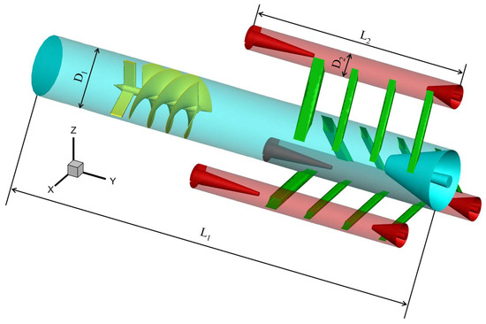
Figure 1.
Structure of the separation core tube with the main and secondary cavities. (The main cavity is represented in cyan, the guide vane is represented in yellow, the secondary cavities are represented in red, and the connecting pipe of the MCSC chambers is represented in green.)

Table 1.
Geometrical data of the separation core tube with the main and secondary cavities.
The MCSC was installed along the Y-direction and the negative direction of the Y-axis is the direction of gravity, and the center of the MCSC inlet was the coordinate origin. The inner diameter of the main cavity was 75 mm, and that of the secondary cavities was 30 mm. One main cavity and three secondary cavities were connected through four tangential pipes with a total cross-sectional area of 660 mm2. The simulation adopted a speed inlet and pressure outlet. Reynolds stress and standard wall functions were set to a viscous model and near-wall treatment, respectively. The Y plus of the wall mesh was in the range of 15–30. The minimum volume and surface mesh size were 2.858908 × 10⁻¹² m3 and 3.279762 × 10⁻¹⁰ m2, respectively, and the maximum volume and surface mesh size were 9.422404 × 10⁻⁷ m3 and 8.185610 × 10⁻⁵ m2, respectively. As the MCSC was installed independently inside the equipment, the light phase outlets of the main and secondary cavities were at the same level, and the pressure was the same. The pressure difference between the light-phase outlet and the heavy-phase outlet at the bottom of secondary cavities was set according to the water pressure difference.
The structure of the MCSC differed from that wherein the outlet was connected to the inlet when the cyclones were connected in series. The tangential connection pipes between the main and secondary cavities of the MCSC were distributed in steps along the axial direction, ensuring that the fluid in the main cavity could be split under the appropriate turbulent intensity and the pre-separation of produced water could be achieved at the light-phase outlet at the upper part of the connecting pipe.
2.2. Construction of New Equipment
Compared to that of onshore oilfields, the central platform of the Bohai oilfield for industrial applications in this study had a small space, short processing flow, high oil viscosity (up to 1358 mPa·s), and high density (specific gravity to water: 0.935–0.967). Moreover, the comprehensive water content of the produced fluid was high (>94%). To further increase the production capacity, the offshore oilfield proposed a plan for hanging wells in the platform to increase the production according to the remaining oil in different formations. As a new wellhead must be added to extract the liquid, it was necessary to simultaneously add a produced water treatment system to the platform.
There is only one set of traditional water treatment processes before the platform improves production. After the produced liquid settles through the three-phase separator, a conventional treatment process comprising a corrugated plate interceptor (CPI), a gas flotator (GF), and a walnut shell filter (WSF) was used to treat the produced water. When the produced water reached the standard, it was reinjected into the formation. This treatment process has a strong adaptability to oil products and is widely used in offshore oilfield platforms at the beginning of construction.
The key to increasing the production of the platform is to ensure that the platform space is small, the load is severely limited, and the bearing requirements of the pile foundation are not met. If the traditional process is still used, it must be applied to a new sea area to construct a produced water treatment platform, which will seriously affect the production time. This study combined MCSCs with fiber coalescence technology [26] to form a novel compact separator. The compact separator was arranged in a slit space with a length and width of 18,000 and 3400 mm, respectively, between the CPI and the GF on the upper deck of the platform. Figure 2 shows the layout of the compact separator.
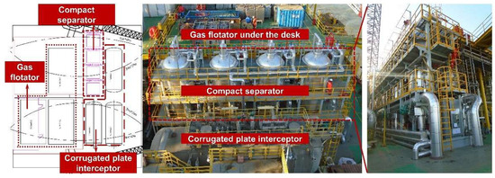
Figure 2.
Layout positions of the compact separator and the device.
After the formation of the new compact separator, the flow field in the MCSC is a “black box”. The separation effect of the MCSC can only be evaluated by the change in the oil content influent and effluent of the MCSC. Electrical resistance tomography (ERT) is based on sensor design and electrode placements. The tomography can provide two (cross-sectional) or three (volumetric reconstruction) pieces of information and finally represent the internal phase distribution as an image. ERT is a promising non-intrusive measurement technique for the real-time monitoring and parameter extraction of dynamic industrial processes [27]. In future work, ERT will be used to analyze the vortex core distribution in the MCSC.
2.3. Process Comparison
After the platform is expanded, the produced water treatment involves two processes, i.e., new and old treatment processes (Figure 3). The old produced water treatment process comprises a production separator, a CPI, a GF, a WSF, and a buffer tank. The newly produced water treatment process comprises a three-phase separator, a compact separator, a fiber ball filter, and a buffer tank. In addition to the necessary three-phase separator and buffer tanks, the three-stage series processing flow of the old process is reduced to two-stage series processing.
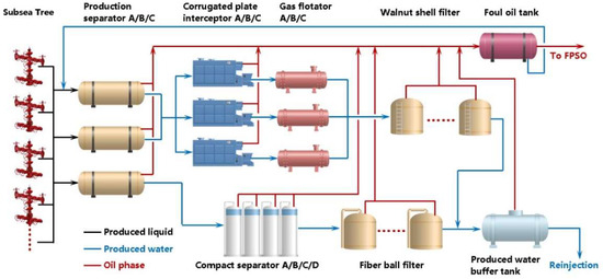
Figure 3.
Produced water treatment process after expanding the capacity.
In the old produced water treatment process, the produced liquid is separated by the gravity sedimentation of oil, gas, and water through two three-phase separators (A and B). Subsequently, the produced water enters the CPI (A, B, and C), the GF (A, B, and C), and the WSF. When the treated effluent reaches the standard, it is discharged into the buffer tank and reinjected into the formation. The total processing capacity of this process was 36,000 m3/d.
In the newly developed water treatment process, the produced fluids are separated by gravity settling through a three-phase separator. However, only one three-phase separator was used in the new process. The settled produced water entered the four compact separators (A, B, C, and D), and was finally treated by a fiber ball filter. When the treated effluent reached the standard, it was discharged into the buffer tank and reinjected into the formation. The total processing capacity of this process was 24,000 m3/d.
All separated oil phases in the new and old processes entered the foul oil tank for further sedimentation. They were then transported to the floating production storage and offloading (FPSO) unit through the sea pipeline for further dehydration treatment, and the oily water phase re-entered the three-phase separator for cyclic separation. The one-stage compact separator replaced the two-stage series equipment of the CPI and the GF. Table 2 presents a comparison of the basic parameters of the compact separator, the CPI, and the GF.
Table 2.
Comprehensive evaluation factor of the produced water treatment equipment.
When the processing capacity of the new process of the platform was 24,000 m3/d, the maximum processing capacity was reached, and all four pieces of equipment were used. In the old process, two CPI and GF units were used to achieve the same processing capacity. The new and old processes under this processing capacity are compared in Table 2. As the current production separators on the platform were similar to those in the model, two production separators were used in the old process. Only one production separator was installed in the new process owing to space constraints, and the oil content at the outlet of the production separator in the new process was higher than that of the production separator in the old process, and the fluctuation was significant. The effluent index of the compact separator was the same as that of the GF (not more than 60 mg/L), and the technical concept of replacing the two-stage equipment with a single-stage equipment was realized. The compact separation technology equipment used the MCSC for pre-treatment and fiber coalescence technology for post-treatment. Based on the current situation, where the height position of the upper deck of the platform was not limited and the plane position could not provide a complete square space, vertical equipment was designed with a diameter of 2400 mm to use the slit space of the upper deck of the platform. Considering the MCSC with the pre-treatment function, the total height from the inlet to the tangent of the upper head of the separator was 1600 mm. It was arranged within a single piece of equipment, and the tangent length of the equipment could be controlled within 3000 mm. The floor area of the compact separator was unaffected by the MCSC.
3. Numerical Simulation
3.1. Selection of Calculation Times
To analyze the stable shape of the internal flow field of the MCSC, the calculation process adopted the transient state, and the relevant parameters of the stable stage time were used for the analysis after the flow was stable. Tecplot 360 was used for data post-processing.
Figure 4 shows that the transient model was used to calculate the flow time of the model from 0 to 10.0 s. Cross-sections were taken at the diameter position of the main cavity and the outermost secondary cavities along the X direction. The cross-sections of the MCSC were intercepted at 340 and 440 mm along the Y direction, respectively, to obtain the intersection lines of the main and secondary cavities in the X and Y directions, respectively, and the two lines were selected to extract the velocity change data.
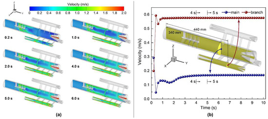
Figure 4.
Selection of the calculation time. (a) States of the sections under different calculation times; (b) changes in the velocity with times at the linear intersection of X and Y sections.
Figure 4a shows the interception of the cross-sectional velocity fields at six times, namely 0.2, 1.0, 2.0, 4.0, 5.0, and 6.0 s. The analysis of the macroscopic velocity field changes shows that the flow field tends to be stable after 4.0 s. To obtain a precise flow field stabilization time, as shown in Figure 4b, the time-dependent data of the velocity at the center point of the cross-section intersection line obtained in the main and the secondary cavities were extracted. The data analysis showed that the flow field in the MCSC stabilized after 4 s. Subsequently, the calculation time was set to 5 s, and the data at 5 s were discussed.
3.2. Detection of the Grid- and Time-Step Independence
In this study, the computational fluid dynamics (CFD) simulation was based on the ANSYS Fluent software. The mesh size and time step significantly affected the final result of the transient calculation. Divergence can easily occur because of the excessive number of cells in the calculation process of a single time step. When fine cells are used, the time-step size naturally needs to be smaller. Simultaneously, the calculation time of a single time step of the fine grid will be significantly longer than that of the coarse grid; when a coarse grid is selected, although a more significant time step can be selected and the calculation time of a single time step is shortened, a coarse grid with a larger grid size may lead to the loss of the local flow field information. The coarse grid may also lead to the divergence of the calculation results with a complex flow field. In conclusion, it is necessary to obtain the best balance between the calculation results and the calculation efficiency. Figure 5 shows the evaluation of independence of the grid and the time step.
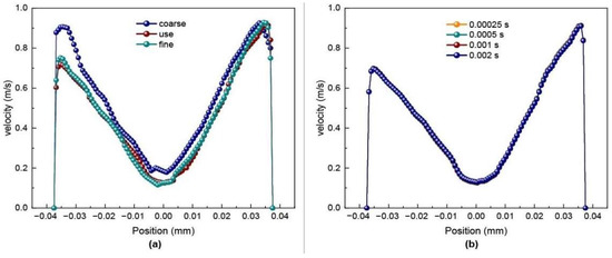
Figure 5.
Independence evaluation of the (a) mesh and (b) time. (a) Independence of mesh; (b) independence of time.
Figure 5a shows that the coarse grid, calculation grid, and fine grid were selected for the calculation. The coarse, calculation, and fine cells included 292,633, 546,737, and 1,100,308 cells, respectively, as shown in Figure 5b; the computation using the intermediate scales was performed using the grid at time steps of 0.00025, 0.0005, 0.001, and 0.002 s. In the evaluation of the grid and time step independence, we calculated the velocity distribution of the section intersection at the 250 mm position in the Y direction and the section at the 0 mm position in the X direction when the flow duration was 5 s.
As the velocity field on the extracted intersection line was close to the first tangential inlet connecting the main and secondary cavities in the Z direction, the velocity presented an incomplete symmetrical form, which is different from the symmetrical form in the traditional swirl field. Additionally, the position velocity of the axis in the Z-direction was relatively small. As the position moved to the side wall, the velocity gradually increased. However, owing to the influence of the boundary layer, the velocity of the flow field at the side wall was zero, and the velocity first increased and then decreased from the side wall to the axis direction.
Figure 5a shows that under the conditions of the three grid sizes, the coarse grid lost the local velocity in the negative direction of the Z-axis owing to the grid size problem. However, the velocity field distributions of the other two grid sizes were relatively consistent. Moreover, the velocity field distribution was close to that in the first tangential inlet in the positive direction of the Z-axis, corresponding with the speculation that a high-speed zone appears in the positive direction of the Z-axis based on the symmetrical traditional swirl field velocity along the axis. When the number of cells was 546,737, a relatively accurate velocity field distribution could be obtained. Further increasing the cell density significantly increases the calculation time, which does not help optimize the calculation results. Therefore, the number of cells selected for the calculation in this study was 546,737 cells. Figure 5b shows that the calculation results for the four-time steps were highly consistent. Considering the increase in the flow rate during subsequent calculations, 0.0005 s was selected as the time step for the calculation process.
Figure 6 shows the meshing of the entire and critical areas during the calculation process. The mesh was divided using Fluent meshing. Key areas, such as the guide vane, tangential opening connecting the central and secondary cavities, and the inlet and outlet, were encrypted. Simultaneously, a boundary layer was constructed on the wall surface, and the mesh type was polyhedral. Compared to the tetrahedral mesh, the polyhedral mesh further compresses the number of meshes and avoids the complexity of the structural mesh to ensure calculation accuracy.
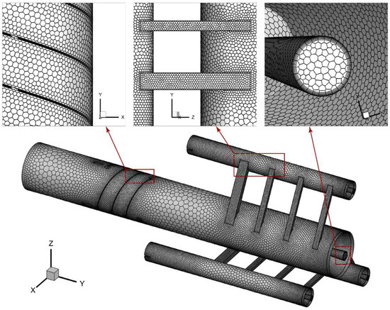
Figure 6.
Mesh used in the calculation.
3.3. Influence of the Inlet Reynolds Number
The processing capacity of the MCSC is key to its treatment effect. Based on the above MCSC, we calculated the flow field distribution of the processing capacity ranging from 3 to 9 m3/h. The inlet processing volume was dimensionless based on the Reynolds number, which can be calculated using Equation (1):
where ρ is the density of the medium (Kg/m3), v is the flow velocity of produced water (m/s), and l is the characteristic length. Here, the guide vanes and connecting pipes were not involved because the selected sections were in the cylindrical section of the main and secondary cavities. The characteristic length is the diameter of the cavity at the corresponding position m, and μ is the viscosity of the produced water (Pa·s).
From the processing capacities of 3 to 9 m3/h, a dataset was obtained at an interval of 1 m3/h, and the inlet Reynolds numbers were 14,147, 18,862, 23,578, 28,294, 33,009, 37,725, and 42,441, respectively. The main cavity cross sections were taken at 0.24 and 0.29 m along the Y direction, and the secondary cavity cross sections were taken at 0.385 and 0.435 m along the Y direction, respectively. Along the Z direction of each section, 100 data points were uniformly obtained for the main cavity, and 50 data points were uniformly obtained for the secondary cavities, as shown in Figure 7a.
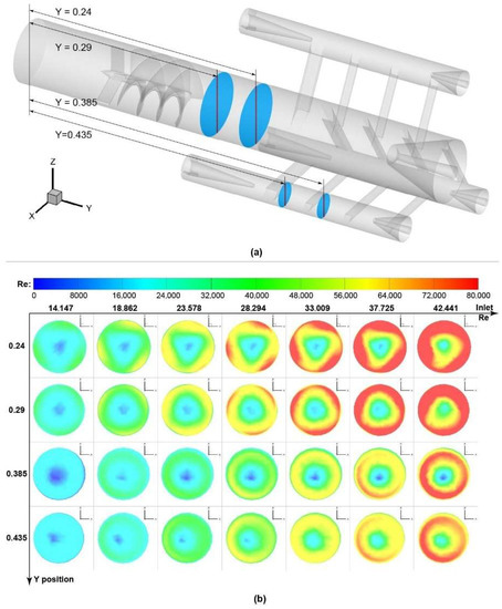
Figure 7.
Critical sections and the contours of the Reynolds number (Re). (a) Positions of critical sections and (b) contours of Re at critical sections.
Figure 7b shows that the Reynolds number at the center of the cavity was relatively low in both the main and secondary cavities. At the same section position, with an increase in the inlet Reynolds number, the critical section moved upward as a whole, but the distribution trend of the Reynolds number remained unchanged. Although the flow velocity in the secondary cavities was higher than that in the main cavity, the Reynolds number remained relatively low owing to the substantially reduced pipe diameter. The cloud diagram of the Reynolds number changes in the two adjacent sections of the main and secondary cavities showed that the distribution of the Reynolds number was not entirely centrally symmetric. Based on the compact structure, the analyzed section position was closer to the tangential connecting pipe of the main and secondary cavities. At the position near the tangential interface, the flow was gradually restricted and the speed increased. Therefore, based on the symmetry of the velocity section, the Reynolds number distribution of the main and secondary cavity sections exhibited eccentric distribution.
Figure 8 shows that except for 42,441, which has the highest imported Reynolds number, the Reynolds number at the center of the main cavity with other inlet Reynolds numbers was lower than 15,000, which is relatively low. However, the Reynolds number increased with the extension of the Y-axis. The Reynolds number of secondary cavities was generally lower than that of the main cavity. With an increase in the imported Reynolds number, the Reynolds number increased with an increase in the inlet Reynolds number regardless of the core position or the top position of the Reynolds number near the side wall.
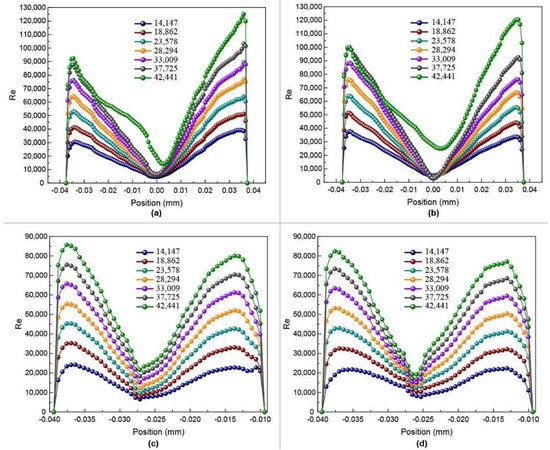
Figure 8.
Re-distribution of the critical section at the Z-direction diameter. (a) Y = 0.24 m in the main chamber; (b) Y = 0.29 m in the main chamber; (c) Y = 0.285 m in the subsidiary chamber; and (d) Y = 0.435 m in the subsidiary chamber.
As the MCSC is used for separation with a slight oil–water density difference, the flow field shape inside a conventional swirl field has not been studied. Instead, the turbulent flow field inside the MCSC is known to lead to the renewal of the interface of the dispersed droplets and promotes the coalescence between droplets. Researchers have confirmed similar phenomena in bubbles, ultra-clean water, and solution systems. The coalescence times of bubbles in ultra-clean water and solution systems are considerably different; the coalescence time of bubbles in ultra-clean water is three to four orders of magnitude higher than that in the solution system. The coalescence time of the newly generated bubbles in the 2 mmol/L sodium dodecyl sulfate solution system is measured in milliseconds. However, the coalescence of bubbles is strongly suppressed after tens of milliseconds [28,29,30].
In the process of oil–water separation, when the Reynolds number is approximately 15,000, the droplet breakage caused by turbulence can ensure the continuous generation of new interfaces and the rapid coalescence between fine droplets, and can avoid the deep emulsification of the continuous oil phase caused by excessive turbulence intensity. In the main cavity, with an increasing inlet Reynolds number, the distribution range of Reynolds number around 15,000 becomes narrower, which is not conducive to the coalescence of droplets caused by the interface renewal. In the range of the secondary cavities, when the corresponding inlet Reynolds number is higher than 28,294, the region with a Reynolds number equal to or below 15,000 no longer exists. The coalescence effect of the droplets caused by the interface renewal is limited, and the separation mechanism in the secondary cavities changes to that of conventional cyclone separation. This is a traditional hydrocyclone separation mechanism separating the continuous and dispersed phases using centrifugal force in the swirling field. A greater swirl strength is necessary to separate heavy oil from water. The high-viscosity dispersed phase leads to an increase in the shear force on the droplets, which leads to the fragmentation of the dispersed phase. Hence, conventional hydrocyclone separation is unsuitable for this system.
The above discussion indicates that in a production water treatment system containing heavy oil, the critical inlet Reynolds number for the best effect under this structure is 28,294, and the corresponding treatment capacity is 6 m3/h. Simultaneously, to ensure a balance between the equipment size and the separation effect, the design processing capacity of the MCSC varies from 4 to 6 m3/h.
4. Results and Discussion
4.1. Separation Effect
The dimensions of the compact separator integrating the two separation technologies were 2400 × 6500 mm (inner diameter × tangent length). The MCSC was distributed in the upper part of the compact separator. As shown by the box with the red dotted line in Figure 9, the liquid from the production separator first entered the MCSC for pre-separation. It then passed through the fiber coalescence module to ensure fine separation. The MCSC was uniformly arranged in the separator cylinder, with a total height of 1600 mm, accounting for approximately 1/4th of the total tangent length of the separator.
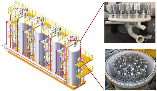
Figure 9.
Model of the compact separator and the installation of the separation tube.
This study mainly focused on the oil content at the inlet and outlet of the MCSC during the operation of a compact separator. As the pre-treated produced water of the MCSC still needed to enter the fiber coalescence module in the compact separator for further processing, the oil content of the MCSC was only monitored during the entire project, and not as the final evaluation index. The operation data of the compact separator were tracked for a total of 33 days, and four groups of oil content data were obtained daily at the inlet and outlet of the MCSC. The data interval between every two groups was at least 2 h. The daily oil content was the average of the inlet and outlet oil contents of all the groups on that day.
Figure 10a shows that during the monitoring process, the average inlet oil content was 1772.81 mg/L, the average outlet oil content was 106.44 mg/L, and the removal efficiency was nearly 94%. From the perspective of water quality analysis, the oil content of the influent water fluctuated relatively wildly; a high oil content exceeded 2000 mg/L; and a low oil content was only approximately 1200 mg/L. However, regardless of the fluctuation in the inlet water quality, the oil content in the effluent was stable and below 200 mg/L after being treated by the MCSC. Compared to the CPI oil remover (the oil contents of the inlet and outlet water reached up to 2000 and 300 mg/L, respectively), the MCSC was more advantageous in terms of both the treatment effect and floor area; the floor space was reduced by more than 60%, and the separation efficiency was increased by approximately 67%. Considering the prior design, traditional hydrocyclones could achieve separation in a compact space. However, the oil on the platform had high viscosity, and the oil–water density difference was small. According to the hydrocyclone theory and the droplet shear force model, sufficient centrifugal strength is required to achieve a good separation effect. However, high centrifugal strength leads to the fragmentation of high-viscosity oil droplets. Thus, traditional hydrocyclone technologies are unsuitable. This is also why current heavy oilfield platforms do not use hydrocyclone separation as part of the produced water treatment process.
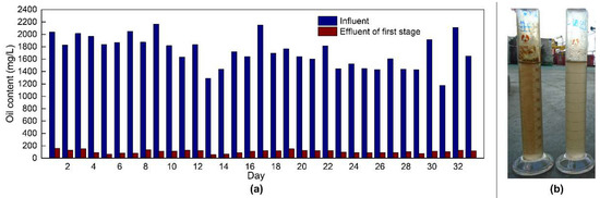
Figure 10.
Treatment performance of the separation tube. (a) Comparison of oil contents between the influent and effluent of the separation tube during the 33 days. (b) Images of the treatment performance of the separation tube.
4.2. Comprehensive Evaluation Index
The comprehensive evaluation index is a commonly used evaluation method for separation equipment to unify the processing capacity and area of the equipment or skid into a comprehensive evaluation index. The two commonly used evaluation indexes are the area evaluation parameter FA and the volume evaluation parameter FV. These are expressed in Equations (2) and (3).
The comprehensive evaluation index of the water treatment equipment produced on land and sea is presented in Table 3. Table 3 lists the indexes of the compact separator, the CPI, and the GF.
where Qave is the average processing capacity of the technical equipment to be evaluated (m3/h); A is the area of the device or skid to be evaluated (m2); and V is the volume of the device or skid to be evaluated (m3). The units of FA and FV are m/h and h−1, respectively.
FA = Qave/A
FV = Qave/V
Table 3.
Comparison of parameters of the main equipment in the new and old treatment processes.
The FA index of the single equipment of the compact separator was 55.3 m·h−1 and the FA index after employing the skid was 34 m·h−1. The comprehensive evaluation index of the equipment processing capacity and floor space was better than that of the CPI. The evaluation index of the single device was lower than that of the hydrocyclone, which was the same as that of the GF. After considering the external instruments, valve pipelines, and control system, the evaluation index of the entire skid was slightly higher than that of the hydrocyclone. According to the data provided by the oilfield, the internal oil removal components of the CPI in the old process were corrugated plates. The GF used in this platform was the induced air flotation, and its FA value was 5.7 m·h−1, which is consistent with the FA range of the commonly used induced air flotation separator in offshore oil and gas fields. According to the data provided by the oil field, the internal components of the inclined plate degreaser in the old process were corrugated plates, belonging to the CPI separator, whose FA value was 6.5 m·h−1, which is consistent with the FA range of the CPI separator used on land. The air flotation device used was the induced air flotation separator, and its FA value was 5.7 m·h−1, which is consistent with the FA range of the commonly used induced air flotation separator in offshore oil and gas fields.
Combined with Table 2, the compact oil–water separator in the new process and the CPI in the old process were compared under the same treatment effect with a treatment capacity of 1000 m3/h. In terms of the floor space, the two CPI units in the old process occupied an area of 152.88 m2, and the two GF units in the old process occupied an area of 176.4 m2; the two-stage equipment in series could reduce the oil content from 2000 mg/L at the inlet to 60 mg/L at the outlet, and the overall floor area was 329.28 m2. Under the same treatment effect, the new process only required a single equipment and covered an area of 59.4 m2. Compared to the old process, the new process reduced the floor area by 81.96% under the same treatment capacity and treatment effect, and the MCSC completely replaced the inclined plate separator. Compared to that in the traditional CPI, if the MCSC was arranged in a separate skid, the floor area in the MCSC reduced by more than 60%. The net weight of the two CPI units in the old process was 144 t. The net weight of the two GF cells in the old process was 174 t, and the overall net weight when the two-stage equipment is connected in series was 318 t. However, the net weight of the single equipment in the new process was 66.6 t. The weight of the new process equipment was reduced by 79.05% compared to that of the old process equipment.
5. Conclusions
Produced water is the most significant byproduct of offshore oil and gas exploitation, and its processing capacity is directly related to the productivity of offshore oilfields. Current produced water pre-treatment is often dominated by gravity sedimentation in heavy oil fields. However, the contradiction between the large area of such a technology and the small operating space of the platform limits the application of such technology in the narrow space of the production platform. In this study, an MCSC system was designed and successfully applied to achieve highly efficient pre-treatment of 24,000 m3/d of produced water in offshore oil and gas fields, and the following conclusions were obtained:
- (1)
- According to the analysis of the internal flow field of the MCSC with a specific size, we determined that the critical inlet Reynolds number for the best effect in the produced water treatment system containing heavy crude oil was 28,294, and the corresponding treatment capacity was 6 m3/h. The design processing capacity under this structure size was determined to be 4–6 m3/h.
- (2)
- Considering the evaluation index of the MCSC, when the inlet oil content fluctuated around 2000 mg/L (average of 1772.81 mg/L), the outlet oil content was stable and fell below 200 mg/L (average of 106.44 mg/L), and the separation efficiency was nearly 94%. Compared to that of the existing CPI on the platform, the floor area was reduced by more than 60%, and the separation efficiency increased by 65%.
The MCSC can achieve the highly efficient pre-treatment of produced water in heavy offshore oilfields and provides a new technology to expand the production of offshore oilfields, especially those that have been put into production, which can significantly reduce the floor area and platform load.
Author Contributions
Conceptualization, Y.L. (Yudong Li) and Y.L. (Yiqian Liu); methodology, Y.L. (Yudong Li) and Q.Y.; validation, H.L. and P.D.; formal analysis, Y.L. (Yudong Li) and H.L.; investigation, Y.L. (Yudong Li) and P.D.; resources, H.Z.; data curation, Y.L. (Yudong Li) and H.Z.; writing—original draft preparation, Y.L. (Yudong Li); writing—review and editing, Y.L. (Yiqian Liu) and Y.Q.; supervision, H.L. and Y.Q.; All authors have read and agreed to the published version of the manuscript.
Funding
This work is supported by the National Natural Science Foundation of China (Grant NO. 52025103), the Shanghai Rising-Star Program (Grant No. 22QA1402600).
Institutional Review Board Statement
Not applicable.
Informed Consent Statement
Not applicable.
Data Availability Statement
The data that support the findings of this study are available from the corresponding author upon reasonable request.
Conflicts of Interest
The authors declare no conflict of interest.
Nomenclature
| MCSC | core tube was coupled with the main cavity and secondary cavities |
| ERT | electrical resistance tomography |
| FA | the area evaluation parameter (m/h) |
| FV | the volume evaluation parameter (h−1) |
| CPI | corrugated plate interceptor |
| GF | gas flotator |
| WSF | walnut shell filter |
| FPSO | floating production storage and offloading |
| CFD | computational fluid dynamics |
| Re | Reynolds number |
| ρ | density (Kg/m3) |
| v | velocity (m/s) |
| l | characteristic length (m) |
| µ | viscosity (Pa·s) |
| Qave | the average processing capacity of the technical equipment to be evaluated (m3/h) |
| A | the area of the device or skid to be evaluated (m2) |
| V | the volume of the device or skid to be evaluated (m3) |
References
- China Energy Research Society. China Energy Development Report 2018; China Building Materials Press: Beijing, China, 2018. [Google Scholar]
- Fu, X.S. Performance Exceeded Expectations and Made Further Progress in Stability; China Petroleum and Chemical Industry Federation: BeiJing, China, 2022. [Google Scholar]
- Pang, X.H. China’s dependence on foreign crude oil is controlled at about 70%. Petro. Refin. Eng. 2019, 64. [Google Scholar]
- Premier Li Keqiang Delivers a Government Work Report (Text Summary). Available online: http://www.gov.cn/premier/2022-03/05/content_5677248.htm (accessed on 5 March 2022).
- Zhou, S.W.; Li, Q.P.; Zhu, H.S.; Zhang, H.H.; Fu, Q. The current state and future of offshore energy exploration and development technology. Strateg. Study Chin. Acad. Eng. 2016, 18, 19–31. [Google Scholar]
- Research Institute of Petroleum Exploration and Development (RIPED). Global Oil and Gas Exploration and Development Situation and Oil Company Dynamics; Petroleum Industry Press: BeiJing, China, 2019. [Google Scholar]
- Zhou, S.W.; Jin, X.J.; Zeng, H.Y.; Zhao, Y.N.; Zhu, J.; You, X.G.; Chen, K.Q.; Bai, G.; Guo, H.; Zhou, C. The facility and equipment of China offshore oil & gas industry. Strateg. Study Chin. Acad. Eng. 2010, 12, 102–112. [Google Scholar]
- Jiang, W. The present situation and prospect of drilling and completion technologies for China offshore oilfield development. Strateg. Study Chin. Acad. Eng. 2011, 13, 58–65. [Google Scholar]
- Ottaviano, J.G.; Cai, J.; Murphy, R.S. Assessing the decontamination efficiency of a three-component flocculating system in the treatment of oilfield-produced water. Water Res. 2014, 52, 122–130. [Google Scholar] [CrossRef]
- Rommel, W.; Blass, E.; Meon, W. Plate separators for dispersed liquid—Liquid systems: The role of partial coalescence. Chem. Eng. Sci. 1993, 48, 1735–1743. [Google Scholar] [CrossRef]
- Cheng, H.N.; Liu, Q.S.; Wang, B.Q.; Zhen, S.Q.; Fu, Z.B. Fluid dynamics simulation and pilot test for polycarbonate liquid-liquid separator. CIESC J. 2013, 64, 2109–2116. [Google Scholar]
- Liang, Z.; Wang, H.M.; Liang, C.P. Study on the inclined plate gas-liquid gravity separation technology. J. Southwest Pet. Univ. Sci. Technol. Ed. 2009, 31, 154–158. [Google Scholar]
- Lv, Y.L.; He, L.M.; Wang, G.D.; Ni, L.Y. Numerical simulation of flow field inside gravitational separator with different internals. China Pet. Mach. 2008, 36, 12–16. [Google Scholar]
- Zandie, M.; Kazemi, A.; Ahmadi, M.; Moraveji, M.K. A CFD investigation into the enhancement of down-hole de-oiling hydro cyclone performance. J. Pet. Sci. Eng. 2021, 199, 108352. [Google Scholar] [CrossRef]
- Liu, H.; Gao, Y.; Pei, X.H.; Zhen, G.X.; Zhen, L.C. Progress and prospect of downhole cyclone oil-water separation with single-well injection-production technology. Acta Pet. Sin. 2018, 39, 463–471. [Google Scholar]
- Zhao, C.; Sun, H.; Li, Z. Structural optimization of downhole oil-water separator. J. Pet. Sci. Eng. 2017, 148, 115–126. [Google Scholar] [CrossRef]
- Qu, Z.Q.; Zhang, Q.; Li, H.; Chen, S.N.; Pu, C.S. Progress and prospect of downhole cyclone oil-water separation with single-wall injection-production technology. J. Xi’an Shiyou Univ. Nat. Sci. Ed. 2006, 3, 34–37. [Google Scholar]
- Shi, L.L.; Yang, G.E.; Yao, S.C. Large eddy simulation of flow past a square cylinder with rounded leading corners: A comparison of 2D and 3D approaches. J. Mech. Sci. Technol. 2018, 32, 2671–2680. [Google Scholar] [CrossRef]
- Cravero, C.; Marogna, N.; Marsano, D. A Numerical Study of Correlation between Recirculation Length and Shedding Frequency in Vortex Shedding Phenomena. WSEAS Trans. Fluid Mech. 2021, 16, 48–62. [Google Scholar] [CrossRef]
- Shu, Z.H.; Liu, G.F.; Chen, W.M.; Chu, L.Y.; Zhong, Y.H. Review on the study for the breakage of drops in Hydrocyclones for oil-water separation. Fluid Mach. 2002, 07, 29–32. [Google Scholar]
- Guo, G.D.; Cao, C.Q.; Shao, H.Y. Analysis of oil droplet deformation model in oil-water dynamic hydrocyclone. IOP Conf. Ser. Mater. Sci. Eng. 2019, 629, 012030. [Google Scholar] [CrossRef]
- Liu, S.; Zhang, D.; Yang, L.; Xu, J. Breakup and coalescence regularity of non-dilute oil drops in a vane-type swirling flow field. Chem. Eng. Res. Des. 2018, 129, 35–54. [Google Scholar] [CrossRef]
- Pang, X.S. Hydrocyclone; Central South University Press: Changsha, China, 2019. [Google Scholar]
- Xu, J.R.; Luo, Q. Flow Field Theory of Hydrocyclone; Science Press: Beijing, China, 1998. [Google Scholar]
- Chu, L.Y.; Chen, W.M. Separation Theory of Rotating Flow; Metallurgical Industry Press: Beijing, China, 2002. [Google Scholar]
- Lu, H.; Liu, Y.Q.; Cai, J.; Xu, X.; Xie, L.S.; Yang, Q.; Li, Y.; Zhu, K. Treatment of offshore oily produced water: Research and application of a novel fibrous coalescence technique. J. Pet. Sci. Eng. 2019, 178, 602–608. [Google Scholar] [CrossRef]
- Sattar, M.A.; Garcia, M.M.; Portela, L.M.; Babout, L. A Fast Electrical Resistivity-Based Algorithm to Measure and Visualize Two-Phase Swirling Flows. Sensors 2022, 22, 1834. [Google Scholar] [CrossRef] [PubMed]
- Liu, B.; Manica, R.; Liu, Q.; Klaseboer, E.; Xu, Z. Coalescence or Bounce? How Surfactant Adsorption in Milliseconds Affects Bubble Collision. J. Phys. Chem. Lett. 2019, 10, 5662–5666. [Google Scholar] [CrossRef] [PubMed]
- Liu, B.; Manica, R.; Liu, Q.; Klaseboer, E.; Xu, Z.; Xie, G. Coalescence of Bubbles with Mobile Interfaces in Water. Phys. Rev. Lett. 2019, 122, 194501. [Google Scholar] [CrossRef] [PubMed]
- Liu, B.; Manica, R.; Zhang, X.; Bussonnière, A.; Xu, Z.; Xie, G.; Liu, Q. Dynamic Interaction between a Millimeter-Sized Bubble and Surface Microbubbles in Water. Langmuir 2019, 34, 11667–11675. [Google Scholar] [CrossRef] [PubMed]


Disclaimer/Publisher’s Note: The statements, opinions and data contained in all publications are solely those of the individual author(s) and contributor(s) and not of MDPI and/or the editor(s). MDPI and/or the editor(s) disclaim responsibility for any injury to people or property resulting from any ideas, methods, instructions or products referred to in the content. |
© 2023 by the authors. Licensee MDPI, Basel, Switzerland. This article is an open access article distributed under the terms and conditions of the Creative Commons Attribution (CC BY) license (https://creativecommons.org/licenses/by/4.0/).