Article

Numerical Simulation Analysis of the Submarine Drilling-Rig Bit Flow-Noise Characteristics

1
National-Local Joint Engineering Laboratory of Marine Mineral Resources Exploration Equipment and Safety Technology, Hunan University of Science and Technology, Xiangtan 411201, China
2
School of Mechanical Engineering, Hunan University of Science and Technology, Xiangtan 411201, China
*
Author to whom correspondence should be addressed.
J. Mar. Sci. Eng. 2023, 11(10), 1845; https://doi.org/10.3390/jmse11101845
Submission received: 14 August 2023 / Revised: 14 September 2023 / Accepted: 20 September 2023 / Published: 22 September 2023

Abstract

:
In cone penetration test (CPT) based on submarine drilling rigs, encountering harder soil layers requires drill-bit rotation. During this process, the flow noise generated by seawater flushing the drill bit propagates along the drill pipe with the detection signal, leading to signal distortion. To improve the accuracy of the received signal and mitigate the impact of flow noise on CPT results, numerical simulation software (Fluent 18.0) was employed to investigate the flow-noise characteristics within the drill-bit borehole during seawater flushing. The effects of key parameters on flow noise are analyzed, and structural optimization to reduce flow noise is conducted. The findings reveal that the noise in the drill-bit flow channel increases as the inlet flow velocity increases. When the flow velocity increases from 10 to 20 m/s, the maximum noise value increases by nearly 30 dB. Similarly, as the rotational speed of the drill pipe increases from 500 to 1500 rpm, the maximum noise value increases three-fold. Furthermore, increasing the inclination angle of the guide hole appropriately reduces the fluid noise in the drill-bit flow channel. For instance, increasing the inclination angle from 0 to 30° reduces the maximum noise by 18.75%. It is important to note that under different flow velocities and rotational speeds, the flow noise is primarily concentrated in the low-frequency band. These results offer valuable insights for the low-noise flow-field optimization design and have significant implications for enhancing the accuracy of wireless acoustic CPT signal reception.

1. Introduction

The oceans are a treasure trove of mineral resources that can be used to support the survival and development of humankind [1]. With the rapid development of the construction of marine engineering facilities, marine geological surveys have become particularly important [2]. Determining the basic physical parameters of the seabed soil, foundation bearing capacity, soil layer, and soil class division, as well as judging the possibility of soil liquefaction, is an important basic work in the development and use of marine resources. Because of the special nature of marine geology, it is difficult to maintain the stress state and nature of the soil in its original state with on-site sampling [3,4]. CPT has the advantage of being fast and accurate compared with seabed sampling and analysis [5,6]. It uses special equipment with a sensor probe that penetrates according to a certain speed pressure into the seabed soil layer and uses the probe’s detected data to ascertain the seabed soil’s physical and mechanical properties. It is an indispensable and important technical means of seabed geotechnical investigation for seabed resource exploration, seabed military, and civilian engineering construction, and the deployment of seabed engineering equipment [7,8]. Subsea CPT equipment can be classified into three basic types according to their working modes: platform, seabed, and downhole [9]. Seabed CPT has certain advantages over the other two modes of operation. First, the cost is relatively low, and general survey vessels can carry it without the need for a specific drillship; second, it is easy to use and can be stowed and released by the aft A-frame, side crane, or midship moon pool. It can obtain real-time data by operating through the deck unit, saving time and cost. Furthermore, the seabed CPT can spatially ensure the integrity of the touchdown path [10]. In particular, the CPT based on the submarine drilling rig is a new type of seabed-type CPT method that overcomes the shortcomings of ordinary seabed-type CPT with shallow testing depth. It is an important direction for developing subsea CPT at present [9,11]. When employing a submarine drilling rig for CPT, the drilling rig provides the downward penetration driving force to the probe. The data collected by the probe are transmitted to the receiver on the drilling rig via sound waves through the drill pipe and subsequently transferred to the support vessel through the armored umbilical cable on the drilling rig [12,13].
Data transmission is an important part of the overall seabed CPT. Of all the data transmitted, the transmission of data collected by the CPT probe to the subsea drilling-rig platform is the most critical link. The ability to achieve efficient and reliable transmission of exploration data in the complex deep seabed environment through the special structure of the touch probe device is related to the success or failure of the whole CPT [12,14]. At present, the vast majority of seabed CPT are used in cable data transmission [7,15], but due to the existence of the cable, the CPT has introduced a series of problems: the need for more than one person to cooperate to pass the cable through each section of the probe rod to complete the probe assembly; the time-consuming and laborious nature of this task, which increases the cost of manpower; and the fact that sea conditions are complex and changeable, and the sea is often accompanied by a large number of wind, waves, and undercurrents so that in the installation and commissioning process it is very easy to damage the cable. Due to complex and changing sea conditions, offshore operations are often accompanied by strong wind, waves, and undercurrents, making it easy to damage the cable during installation and debugging, which can easily lead to the loss of measurement data and probe failure, increasing the difficulty and cost of various types of maintenance; additionally, as the cable is soaked in seawater for a long time, the waterproof sealing and corrosion-resistant requirements are high [16]. Compared with several existing signal transmission methods, the pipe wall acoustic communication method is less affected by the medium inside the pipe and has the characteristics of simple structure, convenience, and quickness, which is very suitable for transmitting the probe signals when using the drilling rig for CPT.
The cross-sectional area of the probe is considerably smaller than that of the drill bit, resulting in a lower soil resistance for the probe compared to the drill bit. In certain instances, the probe can penetrate under a specific amount of force, while the drill bit is unable to continue moving downward, halting the CPT. To address this issue, the drilling rig drives the drill bit to rotate, therefore reducing the frictional resistance of the soil [17]. During drill-bit rotation, seawater flushing is necessary to prevent burning or clogging [18]. However, the flow noise generated by seawater flushing propagates along the drill pipe and the detection signal, distorting the received signal. To enhance the accuracy of the received signal, it is essential to understand the flow-noise characteristics of the drill bit and suppress them effectively.
In a fluid pipeline system, vibration or pulsation caused by the nonstationary force acting on the liquid and the nonstationary pressure field caused by the turbulent motion of the fluid generate flow-generated sound [19]. Many studies on flow noise, such as Lighthill [20], have derived the formula of turbulent motion noise for the first time through the fluid wave equation. The theoretical model of the Lighthill wave equation was established. Xie [21] used the three-dimensional unsteady CFD coupled sound field method to study the flow noise caused by high-temperature liquid sodium in a nuclear primary pump system, obtained the spectral characteristics of the sound source load, and further discussed the sound pressure level distribution along the flow direction of the inlet and outlet ducts. Zhao [22] used the spatial mode decomposition method to theoretically analyze the fine-scale turbulent noise based on the improved Tam–Auriault (TA) model so that experiments do not restrict the analysis of turbulent noise at the fine scale. Li [23] investigated the propagation of low-frequency noise in fluid-filled pipes using numerical analysis. Cheng [24] used the boundary element method to calculate the noise radiation characteristics of the inlet and outlet pipes. In addition, related research mainly focuses on the influence of the structure of the oil drilling bit on the impact force of drilling fluid and the effect of chip removal. Wu [25] simulated and analyzed the flow field of the PDC bit and simulated the migration process of cuttings at the bottom of the hole using the DPM model. Yan [26] calculated the distribution law of the bottom hole drilling fluid flow velocity, pressure drop, and cuttings mass concentration based on the DPM model.
Based on the submarine drilling-rig CPT process, when encountered hard soil layer, it is difficult to continue to touch down, if this time forcibly penetrate easy to cause damage to the equipment, then you need to start the work of the drill bit, so as to reduce the penetration process encountered by the greater resistance, so that the CPT can be carried out in a complete way, and in the work of the drill bit at the same time will be turned on the flushing water, the flushing water in the drill-bit complex flow channel and its own influence will form a complex turbulent flow field at the bottom, the flushing bit caused by flow-field noise will be transmitted in the form of vibration along the acoustic pipe to the signal receiver, therefore increasing the received data The flushing water, under the influence of the complex flow path of the drill bit and itself, will form a complex turbulent flow field at the bottom of the drill bit, and the flow-field noise caused by the flushing drill bit will be transmitted to the signal receiver along the acoustic wave pipeline in the form of vibration, which increases the error of the received data, so it is of great significance to research on the characteristics of the flow-field noise at the flushing part of the drill bit and to reduce the flow-field noise of the position in order to improve the accuracy of the CPT probe experiment.
In summary, many researchers have studied the noise characteristics of pipeline fluids. However, there are few studies on the flow-noise characteristics of submarine drilling-rig bits. To study the influence of flow noise on the CPT results, improve the accuracy of the received signals, and reduce the influence of the flow-field noise of the drill bit on the results of the CPT at this time, this paper adopts numerical simulation software (Fluent 18.0) to study the characteristics of the flow-field noise in the flow channel of the drill bit during the process of seawater flushing the drill bit, and analyzes the influence rule of the main parameters on the flow-field noise. The structure is optimized to reduce the flow-field noise. Structural optimization to reduce the flow-field noise is also carried out.
The next sections of this paper are organized as follows: In Section 2, the theory is presented to establish a mathematical simulation model. In Section 3, numerical simulations and experimental comparisons are carried out to verify its accuracy. In Section 4, the simulation results are given, analyzed, and discussed. Finally, Section 5 concludes the paper with the conclusion of the paper.

2. Theoretical and Simulation Models

2.1. Computational Theory

Through the FLUENT calculates the flow-field distribution in the flushing process of the drill-bit part and analyzes the noise of the flow field of the drill bit by adopting the broadband noise model. The broadband noise model needs to take up a small amount of computational resources, the computation time is short, and the noise distribution of the flow field can be initially obtained through the steady-state calculation, which can then provide a reference for the low-noise optimization design of the flow field quickly [27,28]. Computational Aeroacoustic (CAA) models require high-precision solution methods, accurate meshes, and non-reflective boundary conditions and are therefore computationally expensive [29,30]. Ffowcs Williams and Hawkings (FWH) is the most popular and effective formula for aeroacoustic and hydroacoustic problems, but it is expensive to calculate. On the one hand, there is a need for huge disk storage to hold the volumetric hydroacoustic data in each time step and computational unit. However, there is a large amount of computational time is required to integrate all computational units for acoustic evaluation [31,32,33]. The Reynolds-averaged Navier–Stokes (RANS) equation obtains the turbulence in the broadband model. Then, a semi-empirical correction model is used to calculate the noise power per unit surface area or volume. The broadband model only needs steady-state calculations, whereas the other two models require transient analyses. Therefore, the calculation cost of the broadband model is much lower than that of the other two models, which is suitable for rapid product design [34]. The broadband noise model requires small computing resources and a short computing time. Generally, the noise distribution of the flow field can be preliminarily obtained through steady-state calculations, which can quickly provide a reference for the low-noise optimization design of the flow field.
In this paper, a broadband model is used to analyze the turbulent noise of the drill-bit flow field. Proudma [35] and Lilley [36] use different methods to deduce the sound power caused by isotropic turbulence per unit volume, and both derivations yield acoustic power due to the unit volume of isotropic turbulence as:
P A = α ρ 0 u 3 l u 5 a 0 5
where u and l are the turbulence velocity and length scales, respectively, a 0 is the speed of sound, α is the model constant.
The acoustic power also can be described by turbulent kinetic energy k and the dissipation rate ε :
M t = 2 k a 0
P A = α ε ρ 0 ε M t 5
where α ε is rescaled constant, it is set to 0.1 in Fluent [37].
The acoustic power level (APL) is defined as:
L P = 10 log ( P A P r e f )
where P r e f is the reference acoustic power, and its value is 10 12 W.

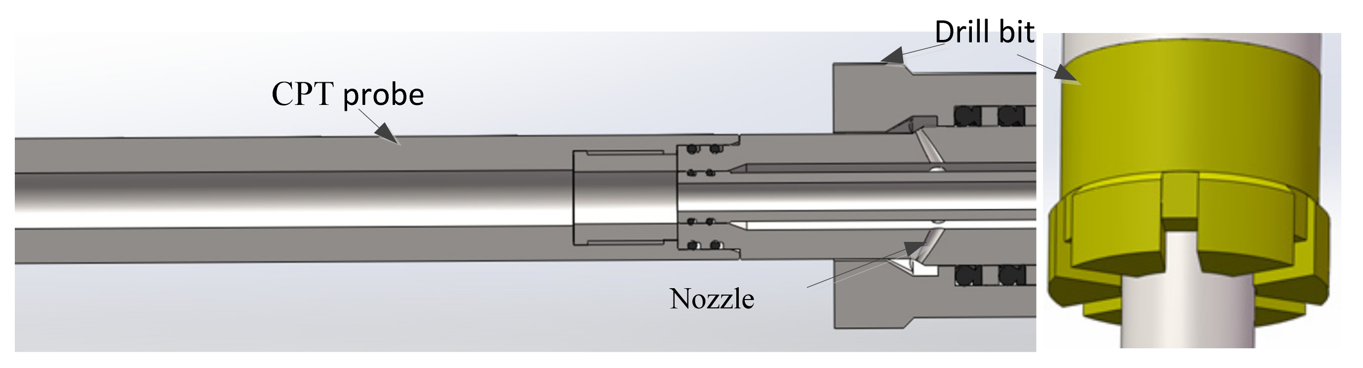
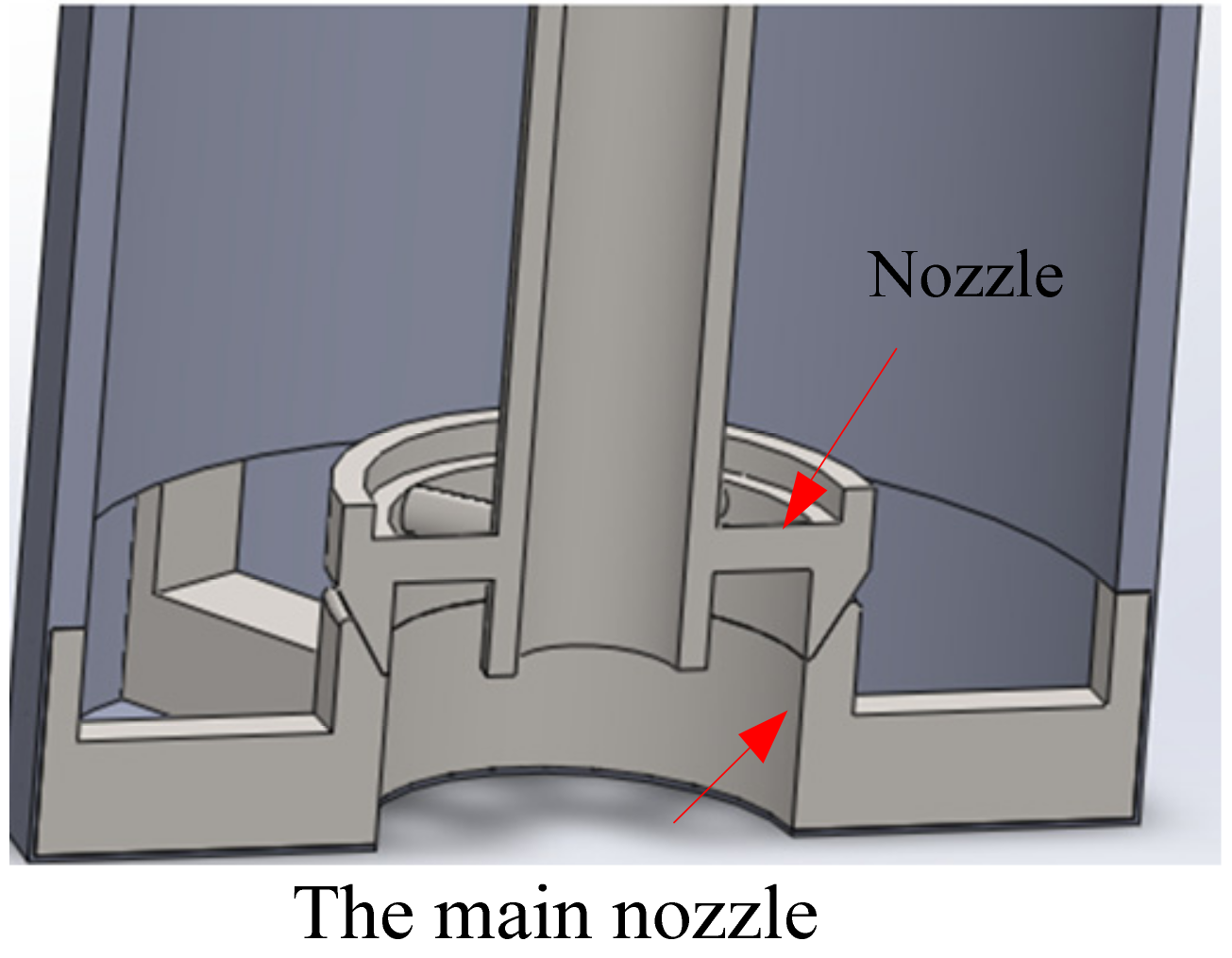
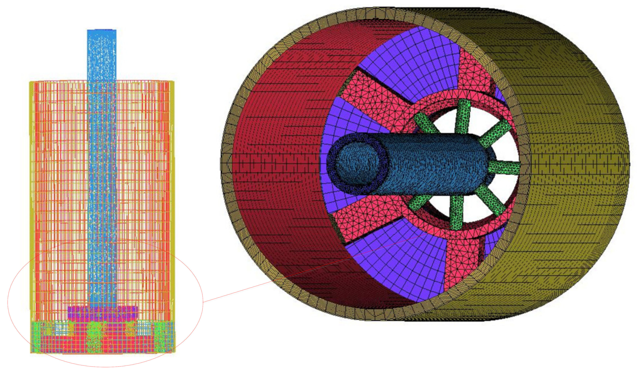
2.2. Analysis Model and Boundary Conditions

A structural diagram of the CPT bit part based on the submarine drilling rig is shown in Figure 1. It mainly consists of two parts: the drill-bit assembly and the CPT probe. The probe is at the center of the drill bit, is independent of the drill bit, and has no influence on the distribution of the flow field; therefore, it can be disregarded in the next analysis. The high-pressure seawater first flows into the main nozzle of the drill bit through the nozzle, then rotates in the main nozzle of the drill bit with the rotation of the bit, and finally returns through the hole wall of the bit. According to the fluid flow at the drill-bit position, a sectional view of the established three-dimensional flow field is shown in Figure 2. The flow-field grid of the calculation model can be installed according to the three-dimensional diagram of the flow channel of the cone penetration drill bit. These meshes were generated using ANSYS ICEM CFD mesh generation software (ICEM CFD 18.0), as shown in Figure 3. The flow field of the drill bit is divided by a tetrahedral mesh, and the mesh density is increased at the nozzle of the drill bit to meet the calculation requirements. The medium in the flow field is seawater, its density is 1050 kg/m3, the propagation velocity of sound waves in water is 1500 m/s, the reference sound power is 10−12 W, the k-epsilon turbulence model is used, the inlet velocity and outlet pressure are set as 5 m/s and 2 MPa, respectively, the wall roughness is 0.0032 mm.

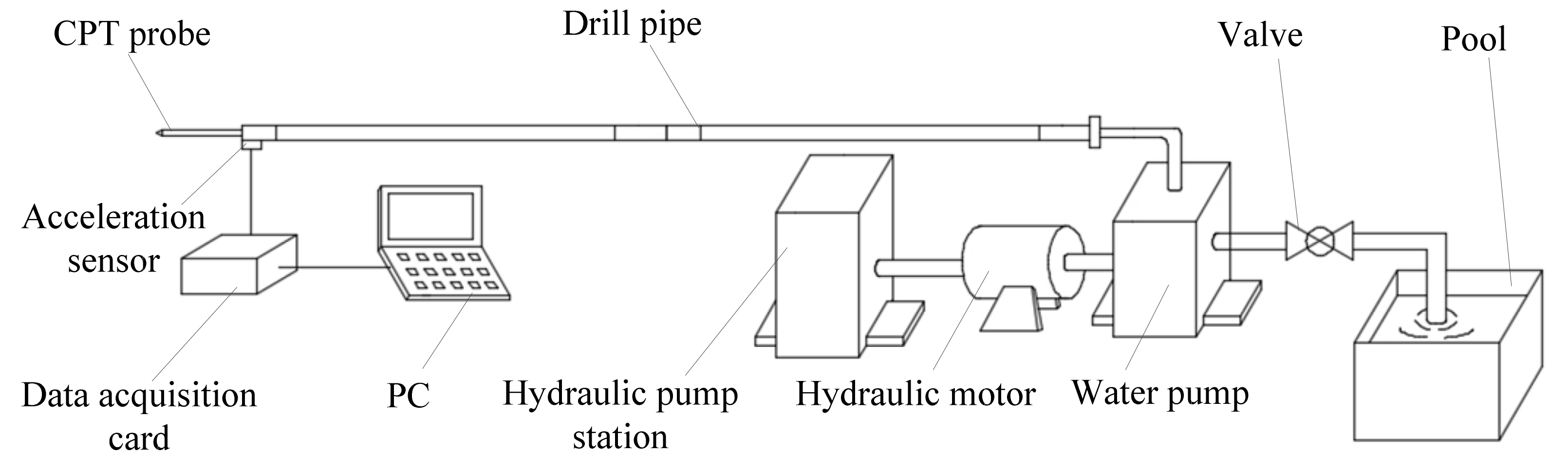
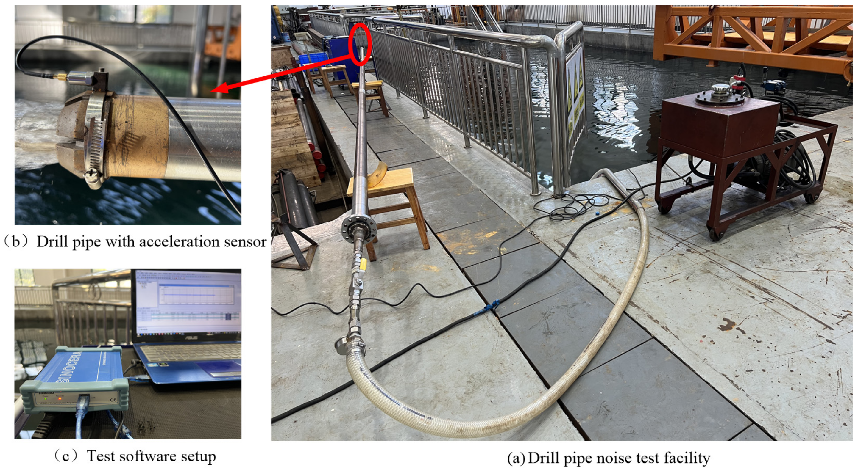
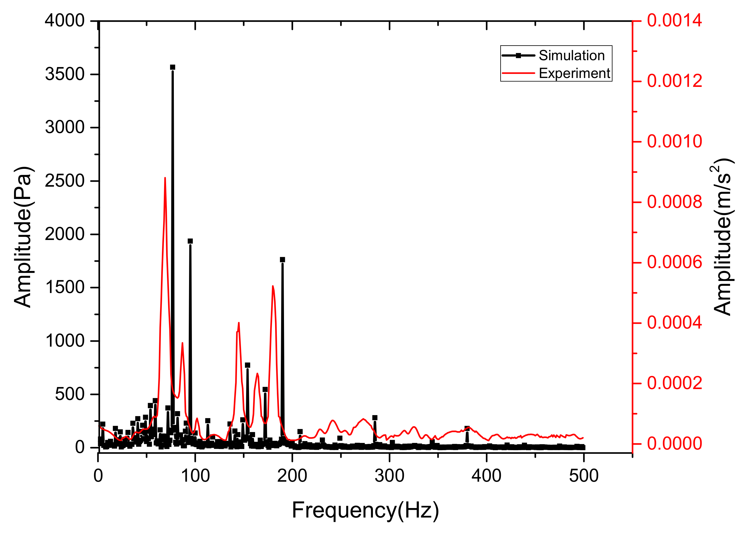
3. Experimental Verification

The system shown in Figure 4 was used for experiments to verify the simulation results. The experiment mainly studies the noise characteristics of the drill bit when the drilling pipe is flushed at a specific flow rate. The volume flow rate was 35 L/min, and photos of the experimental systems and devices are shown in Figure 5.
The maximum sampling rate of YE6231 dynamic data acquisition is 96,000 Hz. The accelerometer used in this experiment was a CA-YD-1182 accelerometer. Specifications are shown in Table 1.
The flow-noise characteristics of the bit at a specific flow rate can be measured by placing the drill pipe on the support and installing an acceleration sensor at the bit, as shown in Figure 5b. The plunger pump and hydraulic motor are immersed in the tank, and the hydraulic pump station is started so that the hydraulic motor drives the plunger pump to flush the drill pipe. The pipe was filled with water for more than 3 min to eliminate bubbles in the drill pipe.
The analysis bandwidth of the collector was set as 0-500 Hz, and the corresponding sampling frequency was set to 5000 Hz by the Nyquist law, with a sampling time of 10 s. The time-domain signal was processed by fast Fourier transform (FFT) to obtain the amplitude of the corresponding conditions. The obtained spectral diagram of the experimental flow noise was compared with the simulation data under the same conditions, as shown in Figure 6. The results show that the simulation results are consistent with the experimental results. When the frequencies are around 77 Hz, 95 Hz, 154 Hz, 172 Hz, and 192 Hz, the experiment and simulation noise peaks appear simultaneously, which shows the correctness of the simulation theory and model adopted in this paper.

4. Discussion

To understand the characteristics of the flow field at the bit position, the flow field of the drill-bit position under different flow velocities, rotational speeds, and nozzle inclination angles were calculated, and the spectral characteristics under the corresponding working conditions were obtained.

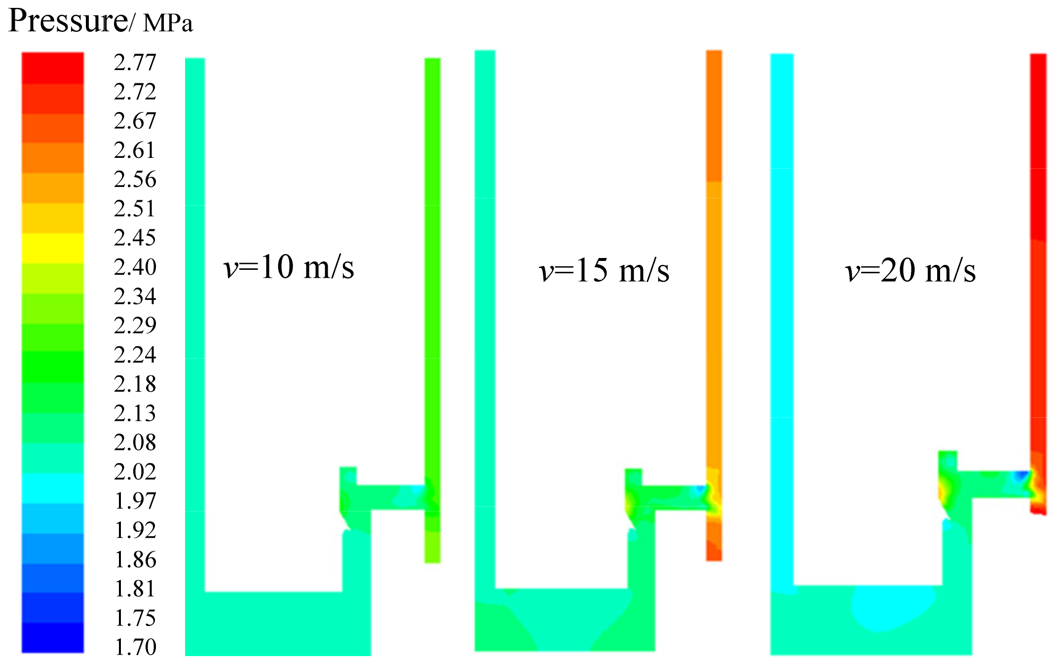
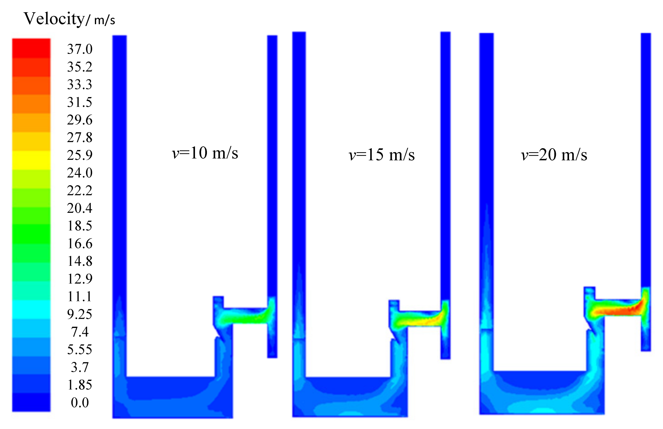
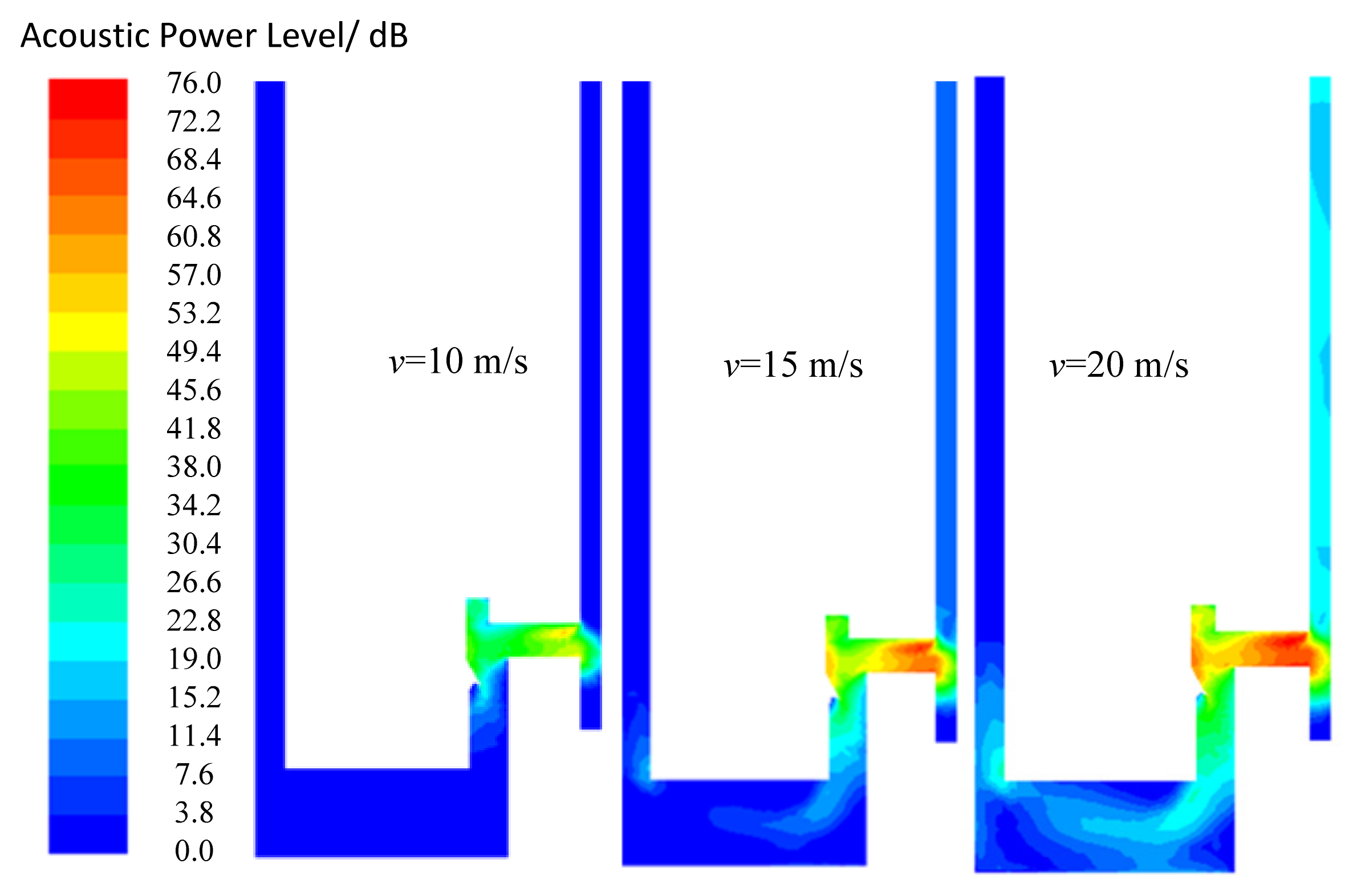
4.1. Influence of Flow Velocity on Flow-Field Characteristics

When the inlet velocity increases from 10 to 20 m/s, the static pressure, flow velocity, and noise distribution on the middle cross-section are shown in Figure 7, Figure 8 and Figure 9, respectively. The static pressure near the hole presents a noticeable gradient. Because of the pressure difference, the fluid in the high-pressure area will move to the liquid in the low-pressure zone. When the low-and high-pressure fluids meet, an impact is bound to occur, which will lead to flow noise. This is well demonstrated in the noise profile in this section in Figure 9.
At the same time, with a gradual increase in the inlet velocity, a prominent high flow velocity area appears on the lower wall of the communication hole. The reason for this is that the flow channel suddenly has a 90° turning angle. Part of the fluid flows into the drill bit through the underside of the nozzle, resulting in an area of high-flow velocity at the bottom. It can also be seen from the flow velocity map that there is a low flow velocity area in the upper part of the flow channel of the drill bit, which may lead to the deposition of rock sand at this position, which is not easily washed out.
From the noise distribution diagram in Figure 9, it can be seen that the flow noise at the drill bit mainly occurs near the nozzle, and the noise value increases gradually with the flow velocity. When the inlet velocity increases from 10 to 20 m/s, the maximum noise at this position increases by nearly 30 dB. In the subsequent design, we should reduce the flow-field noise at this position.

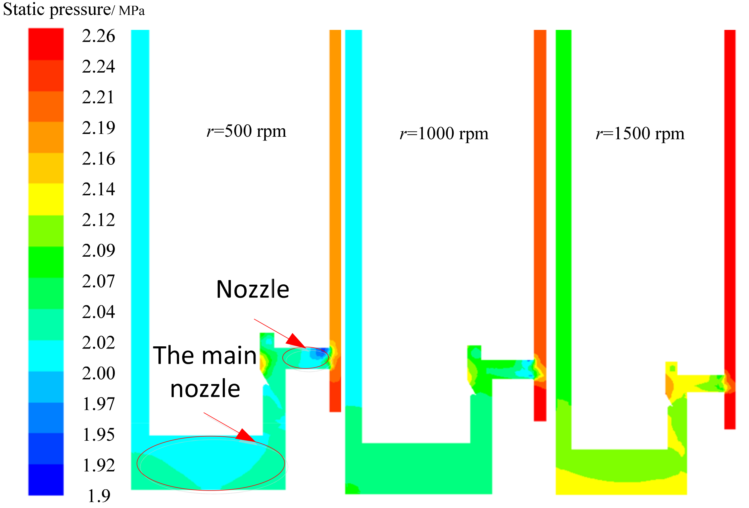
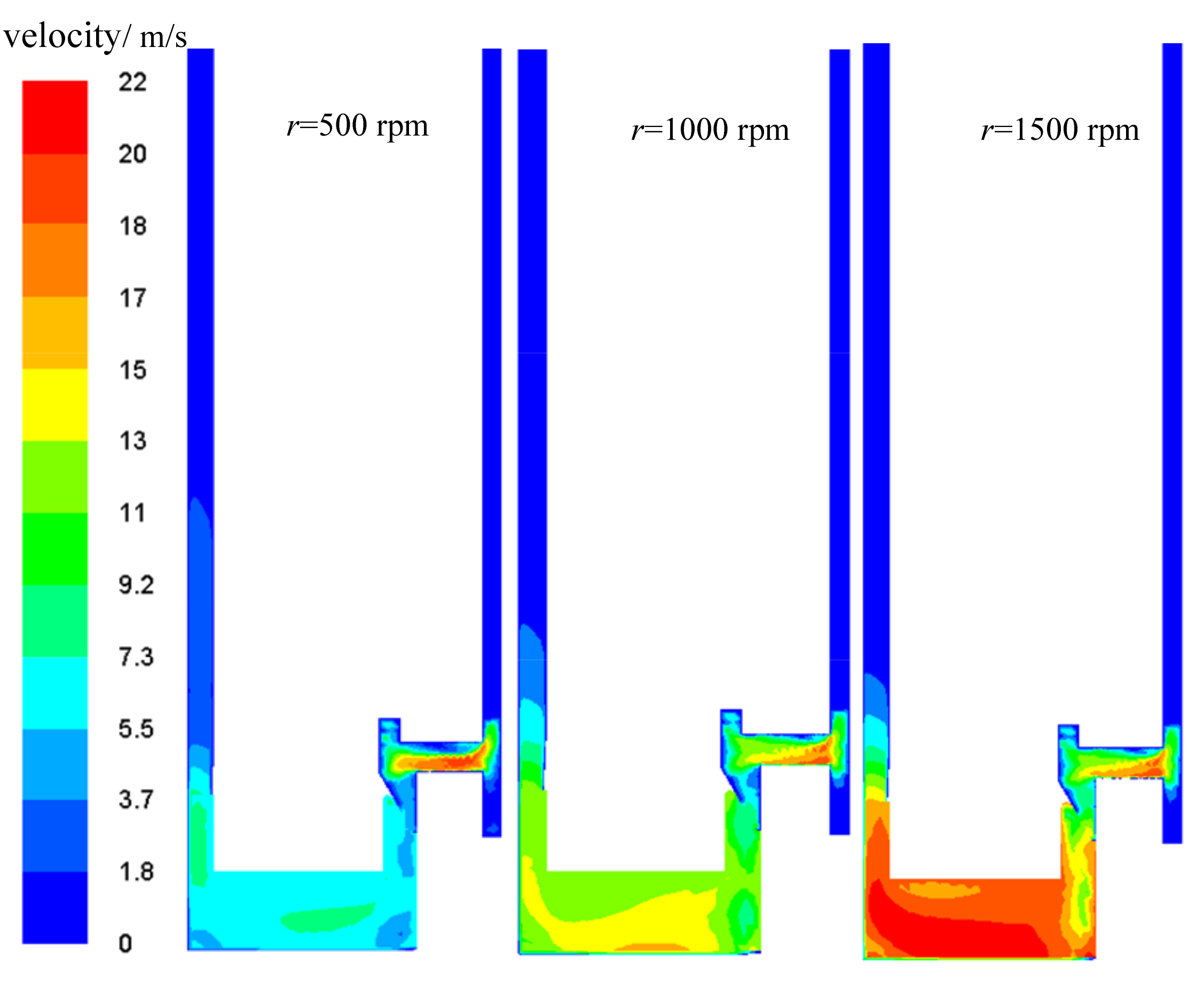
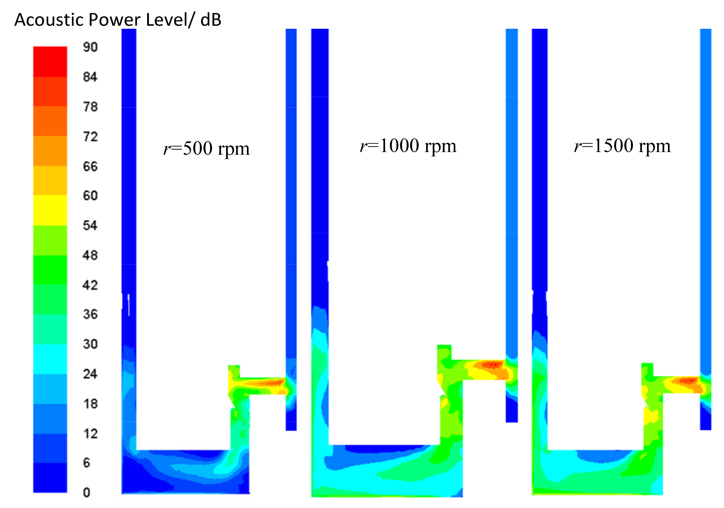
4.2. Influence of Rotational Speed on Flow-Field Characteristics

The rotational speed of the drill pipe is an important parameter that needs to be determined during the drilling process, which affects the flow-field noise at the drill bit and the scouring effect of the residual rock and sand. The static pressure, velocity, and noise distribution cloud diagrams of the middle section of the drill bit are shown in Figure 10, Figure 11 and Figure 12.
It can be seen from this that the rotational speed of the drill bit should be appropriately reduced to reduce the flow-field noise at the drill bit.
It can be seen from the figure that with the gradual increase in the rotational speed, the static pressure and flow velocity of the main nozzle of the drill bit gradually increase. The static pressure and flow velocity of the fluid increase simultaneously, and the noise sound pressure level of the main nozzle also increases. The flow velocity and pressure increase while strengthening the flow instability, thus increasing the noise at this location. It can also be seen from the figure that increasing the rotational speed mainly increases the flow-field noise value and its distribution area in the main nozzle. The maximum noise position rises from approximately 12 to 36 dB, and the noise value at the absolute position of the main nozzle at 500 rpm is approximately 10 dB. At 1500 rpm, the noise value at most parts of the main nozzle increases to approximately 35 dB.

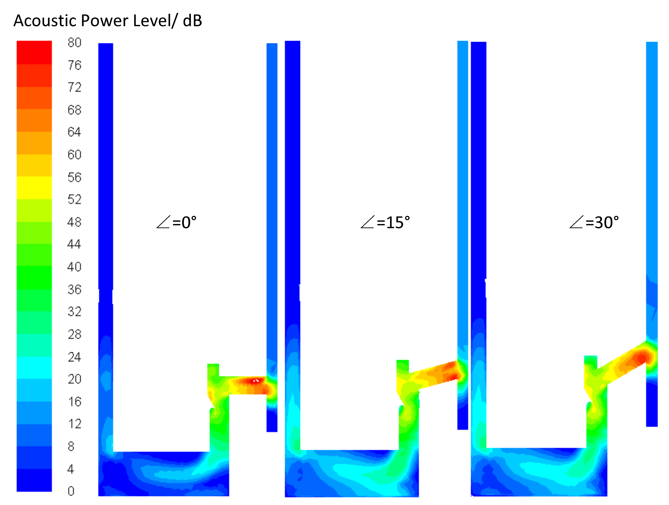
4.3. Influence of Bit Nozzle Inclination on Flow-Field Characteristics

It can be seen from the above noise cloud map that the higher noise value is mainly concentrated at the nozzle. To reduce the flow noise of the nozzle, the inclination angle of the nozzle is optimized, and the inclination angle is calculated from 0 to 30° in the flow field. The maximum inclination angle is calculated only at 30°. If the inclination angle is further increased, the nozzle will be very long, which will bring great difficulties to the processing and manufacturing and is not applicable in engineering.
The calculated flow noise cloud images at different inclination angles are shown in Figure 13. It can be seen from the figure that as the inclination angle increases, the maximum noise value at the nozzle gradually decreases (from 80 to 75 dB). The area of the high noise distribution area gradually decreases. At the same time, with a gradual increase in the inclination angle, the impact noise at the vertical wall of the nozzle also decreases. Although the dip angle of the nozzle slightly increases the flow noise in the main nozzle of the bit, according to the principle of noise superposition, the increase in the low-noise value has a more negligible effect on the final synthesized noise. In other words, an appropriate growth of the inclination angle has a particular significance in reducing the flow noise in the drill-bit area.

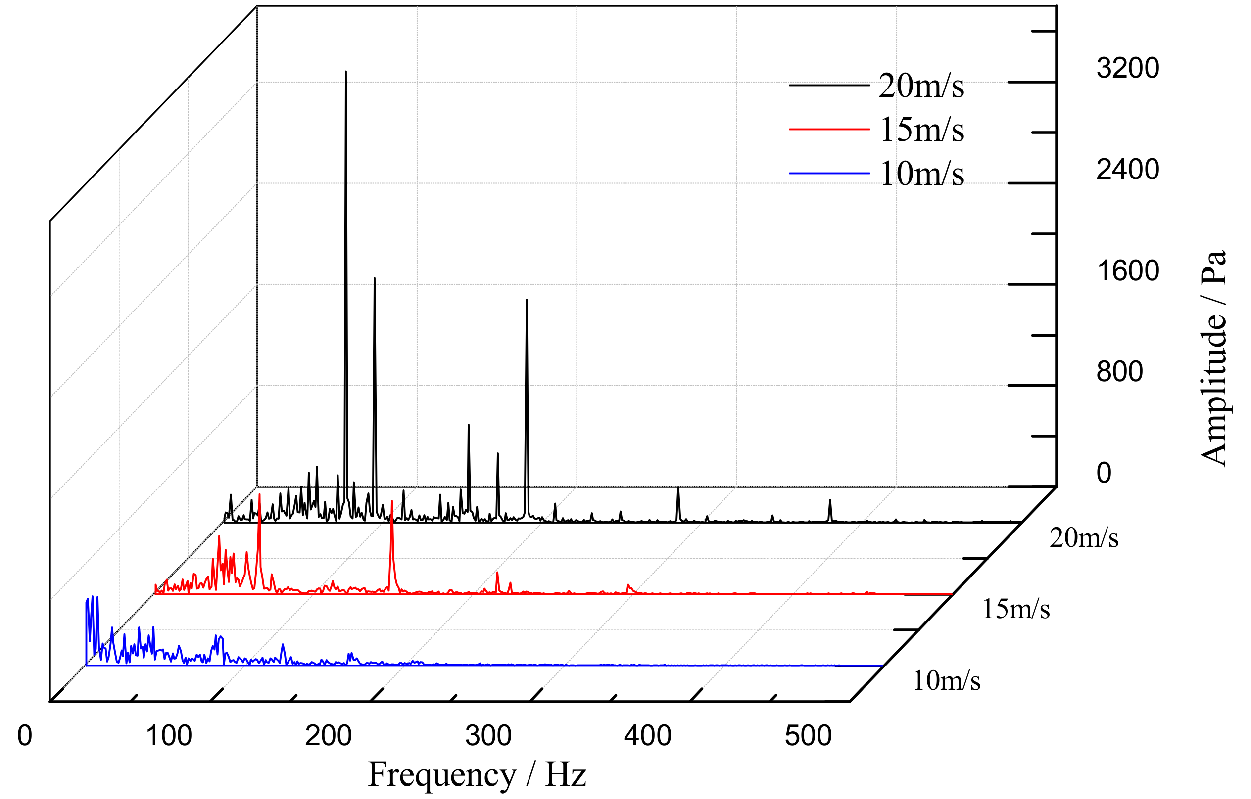
4.4. Analysis of Frequency Spectrum Characteristics of Low Flow-Noise Bit Structure

Figure 14 shows a comparison of the flow-noise spectrum of the drill bit when the inlet velocity is from 10 to 20 m/s. It can be seen that with the increase of the inlet flushing water flow velocity, the noise in the flow channel becomes greater, and the higher the noise peak value, mainly concentrated in the vicinity of 100 to 200 Hz. The fundamental frequency spectrum at 20 m/s contains noise signals from 0 to 400 Hz, including seven noise peaks, reaching a maximum of 3210 Pa. The noise peak may be generated by the turbulent flow of the flushing fluid flow channel. According to the rugged flow characteristics of the fluid, if the high-speed fluid is rapidly compressed in the flow channel, it may produce a noise similar to a squeal [38]. It can be seen that there are cross-sectional variations in the flushing water flow path, which leads to uneven flow rates and causes turbulence. The faster the flow rate of the rinse water at the inlet, the more noise is generated at different frequencies. The greater the interference of regular acoustic communication from the drill pipe, the more it becomes necessary to analyze the noise characteristics of the flow channel structure.
Figure 15 compares the flow-noise spectrograms when the drill rotational speed is from 500 to 1500 rpm. It can be seen that the distribution trend of the drill speed relative to the noise is the same, mainly in the low-frequency region between 0 and 200 Hz. At the same flow rate, the amplitude of the noise increases with increasing rotational speed and tends to be stable when the rotational speed is greater than 1000 rpm. Previous studies have shown that turbulent flow in a rotating circular tube tends to be laminar, which reduces the friction coefficient on the wall of the circular tube [39]. At the same time, the circumferential shear effect of the flow is enhanced [40]. The rotational effect of the pipe wall suppresses the axial turbulent pulsation but enhances the circumferential tumultuous vibration. The rotational effect significantly changes the correlation between near-wall turbulent pulses, and the transport capacity of turbulent pulsations decreases in the rotating state [41]. Due to the rotation of the drill bit, the flow of the flushing water is laminated, and the pulsation of the axial turbulent flow is suppressed. The transportation capacity of the tumultuous vibration is reduced, which makes the noise stable when the drill bit reaches a specific speed condition.

5. Conclusions

In summary, numerical simulation software (Fluent 18.0) was used to study the noise characteristics of the flow field in the drill hole during seawater flushing, and the accuracy of the simulation results was verified in the experimental system. The simulation results show that the flow-field noise mainly occurs at the nozzle position, and the noise value increases gradually with the flow velocity. With increasing rotational speed, the main bit’s static pressure and flow velocity increase progressively, and the noise pressure level of the main bit also increases. The maximum noise value reached 36 dB. With the flow velocity of inlet flushing water, the more noise appears in the flow channel, the higher the noise peak value. At the same flow rate, the amplitude of the noise increases with increasing bit speed and finally tends to be stable. With an increase in the nozzle angle, the nozzle maximum noise gradually decreases, and the location of the distribution of the high noise area also gradually reduces. An appropriate increase in the nozzle angle can reduce the flow noise of the drill bit. Finally, the flow noise at different flow rates and speeds is mainly concentrated in the low-frequency band. The research results reference the optimization design of flow fields with low noise. They are of great significance for improving the accuracy of the received signal of wireless acoustic CPT.

Author Contributions

Conceptualization, J.X. and Y.X.; methodology, J.X.; software, Y.X.; investigation, X.T.; resources and validation, B.W.; writing—original draft preparation, J.X.; writing—review and editing, W.Q.; visualization, X.T.; supervision, B.W. All authors have read and agreed to the published version of the manuscript.

Funding

This research was funded by the China Postdoctoral Science Foundation (Grant No. 2023M731822), the National Natural Science Foundation of China (Grant No. 51709102), the Natural Science Foundation of Hunan Province (Grant No. 2019JJ50166), and the Scientific Research Found of Hunan Provincial Education Department (Grant No. 19B184, Grant No. 20C0825).

Institutional Review Board Statement

Not applicable.

Informed Consent Statement

Not applicable.

Data Availability Statement

Not applicable.

Acknowledgments

The authors thank the anonymous reviewers for constructive comments that helped improve this manuscript.

Conflicts of Interest

The authors declare no conflict of interest.

References

  1. Lijith, K.P.; Malagar, B.R.C.; Singh, D.N. A comprehensive review on the geomechanical properties of gas hydrate bearing sediments. Mar. Pet. Geol. 2019, 104, 270–285. [Google Scholar] [CrossRef]
  2. Wei, J.; Fang, Y.; Lu, H.; Lu, H. Distribution and characteristics of natural gas hydrates in the Shenhu Sea Area, South China Sea. Mar. Pet. Geol. 2018, 98, 622–628. [Google Scholar] [CrossRef]
  3. Mario, M.; Vahid, G. An explicit coupled MPM formulation to simulate penetration problems in soils using quadrilateral elements. Comput. Geotech. 2022, 145, 104697. [Google Scholar]
  4. Campo, B.; Bruno, L.; Amorosi, A. Sedimentary facies characterization through CPTU profiles: An effective tool for subsurface investigation of modern alluvial and coastal plains. Sedimentology 2023, 70, 1302–1327. [Google Scholar] [CrossRef]
  5. Yi, X.L.; Tan, S.A.; Phoon, K.K. Friction angle and overconsolidation ratio of soft clays from cone penetration test. Eng. Geol. 2020, 274, 105730. [Google Scholar]
  6. Zheng, G.; Yu, W. CPT-based probabilistic liquefaction assessment considering soil spatial variability, interpolation uncertainty, and model uncertainty. Comput. Geotech. 2022, 141, 104504. [Google Scholar]
  7. Lunne, T.; Robertson, P.K.; Powell, J.J. Cone-penetration testing in geotechnical practice. Soil Mech. Found. Eng. 2009, 46, 237. [Google Scholar] [CrossRef]
  8. Wang, Z. The Chinese CPT and the prospect of penetration tests. Chin. J. Geotech. Eng. 2000, 22, 517–522. [Google Scholar]
  9. Li, S.; Dai, X.; Zhou, Y.; Jiang, B. Study on the penetration mechanism of Seabed CPT and Downhole CPT. Ocean Eng. 2016, 34, 35–40. [Google Scholar]
  10. Lunne, T. The CPT in offshore soil investigations—A historic perspective. Proc. CPT 2010, 10, 71–113. [Google Scholar]
  11. Yost, K.; Green, R.A.; Upadhyaya, S. Assessment of the efficacies of correction procedures for multiple thin layer effects on Cone Penetration Tests. Soil Dyn. Earthq. Eng. 2021, 144, 106677. [Google Scholar] [CrossRef]
  12. Guo, S.; Liu, R. Application of cone penetration test in offshore engineering. Chin. J. Geotech. Eng. 2015, 37, 207–211. [Google Scholar]
  13. Liu, D.S.; Jin, Y.P.; Wan, B.Y. Review and Development Trends of Deep-sea Mineral Resource Core Sampling Technology and Equipment. China Mech. Eng. 2014, 23, 3255–3265. [Google Scholar]
  14. Martins, J.B.; Correia, A.G.; Teixeira, A.; Mendes, P.M. Wireless in geotechnical engineering: A CPTUwl prototype. In Proceedings of the Fourth International Conference on Site Characterization, ISC’4, Pernambuco, Brazil, 18–21 September 2012; Volume 4. [Google Scholar]
  15. Zhang, X.; Lin, C.M. Use of the Cone Penetration Testing (CPT) method to interpret late Quaternary tide-dominated successions: A case study from the eastern China coastal plain. Cont. Shelf Res. 2018, 161, 49–57. [Google Scholar] [CrossRef]
  16. Qi, C.; Xia, L.; Zhang, W. Underwater short distance magnetic communication based on coupling coils in sealed metal bin. Int. J. Comput. Sci. Math. 2023, 17, 138–151. [Google Scholar] [CrossRef]
  17. Dsxpd, A.; Zwl, A.; Bo, C. Bearing capacity analysis of offshore pipe piles with CPTs by considering uncertainly—ScienceDirect. Comput. Geotech. 2020, 126, 103731. [Google Scholar]
  18. Peng, F.F.; Wang, J.L.; Wan, B.Y. Optimization of key mechanism of the wire-line coring drilling tool for submarine hard rock. Geol. Explor. 2020, 65, 154–162. [Google Scholar]
  19. Wang, Y.L.; Wang, Z.D.; Song, Z.F. Review of vibration and noise control technology in piping system for submarines. Ship Sci. Technol. 2008, 30, 34–38. [Google Scholar]
  20. Lighthill, M.J. On Sound Generated Aerodynamically. II. Turbulence as a Source of Sound. Proc. R. Soc. Lond. Ser. A Math. Phys. Eng. Sci. 1954, 222, 1–32. [Google Scholar]
  21. Xie, Z.; Shen, N.; Ge, J. Analysis of the flow noises of the nuclear main pump caused by the high temperature liquid Sodium in the two-circuit main loop liquid Sodium pump system. Ann. Nucl. Energy 2020, 145, 107550. [Google Scholar] [CrossRef]
  22. Zhao, W.; Jiang, Z.; Wang, X. Characteristics of fine-scale turbulence noise evaluated by modal analysis. Appl. Acoust. 2020, 160, 107145. [Google Scholar] [CrossRef]
  23. Li, Q.; Song, J.P.; Shang, D.J. Experimental Investigation of Acoustic Propagation Characteristics in a Fluid-Filled Polyethylene Pipeline. Appl. Sci. 2019, 9, 213. [Google Scholar] [CrossRef]
  24. Cheng, G.F.; Zhang, W.P.; Wu, G.W. Radiation Characteristics of Noise from Inlet and Outlet of Seawater Piping System. Ship Eng. 2005, 27, 55–58. [Google Scholar]
  25. Wu, Z.B.; Wang, Y.Y.; Pan, Y.J. Comparative Study on Simulation of Rotating Flow Field and Non-rotating Flow Field of PDC Bit. Oil Field Equip. 2020, 49, 10–15. [Google Scholar]
  26. Yan, Y.; Guan, Z.C.; Yan, W.J. Study of Dual-Stage PDC Bit Flow Field Based on Discrete Phase Model. China Pet. Mach. 2019, 487, 5–13. [Google Scholar]
  27. Huang, J.Y.; Zhang, K.; Li, H.Y. Numerical simulation of aerodynamic noise and noise reduction of range hood. Appl. Acoust. 2021, 175, 107806. [Google Scholar] [CrossRef]
  28. Chen, G.; Liang, X.F.; Zhou, D. Numerical study of flow and noise predictions for tandem cylinders using incompressible improved delayed detached eddy simulation combined with acoustic perturbation equations. Ocean Eng. 2021, 224, 108740. [Google Scholar] [CrossRef]
  29. Stuermer, A.; Yin, J.; Akkermans, R. Progress in aerodynamic and aeroacoustic integration of CROR propulsion systems. Aeronaut. J. 2014, 118, 1137–1158. [Google Scholar] [CrossRef]
  30. Stuermer, A.W.; Akkermans, R.A. Validation of aerodynamic and aeroacoustic simulations of contra-rotating open rotors at low-speed flight conditions. In Proceedings of the 32nd AIAA Applied Aerodynamics Conference, Atlanta, GA, USA, 16–20 June 2014; Volume 3133. [Google Scholar]
  31. Wang, Y.; Mikkola, T.; Hirdaris, S. A fast and storage-saving method for direct volumetric integration of FWH acoustic analogy. Ocean Eng. 2022, 261, 112087. [Google Scholar] [CrossRef]
  32. Sezen, S.; Atlar, M. Numerical investigation into the effects of tip vortex cavitation on propeller underwater radiated noise (URN) using a hybrid CFD method. Ocean Eng. 2022, 266, 112658. [Google Scholar] [CrossRef]
  33. Stuermer, A.; Akkermans, R.A.D. Multidisciplinary analysis of CROR propulsion systems: DLR activities in the JTI SFWA project. CEAS Aeronaut. J. 2014, 5, 265–277. [Google Scholar] [CrossRef]
  34. Giauque, A.; Ortun, B.; Rodriguez, B.; Caruelle, B. Numerical error analysis with application to transonic propeller aeroacoustics. Comput. Fluids 2012, 69, 20–34. [Google Scholar] [CrossRef]
  35. Proudman, I. The Generation of Noise by Isotropic Turbulence. Proc. R. Soc. A 1952, 1116, 119–132. [Google Scholar]
  36. Lilley, G.M. The Radiated Noise from Isotropic Turbulence Revisited; NASA Contract Report 93-75; NASA Langley Research Center: Hampton, VA, USA, 1993.
  37. Sarkar, S.; Hussaini, M.Y. Computation of the Sound Generated by Isotropic Turbulence; NASA Contract Report 93–74; NASA Langley Research Center: Hampton, VA, USA, 1993.
  38. Visconti, G.; Ruggieri, P. Turbulence. In Fluid Dynamics; Springer: Berlin/Heidelberg, Germany, 2020. [Google Scholar]
  39. Orlandi, P.; Fatica, M. Direct simulations of turbulent flow in a pipe rotating about its axis. J. Fluid Mech. 1997, 343, 43–72. [Google Scholar] [CrossRef]
  40. Liu, N.S.; Lu, X.Y.; Zhuang, L.X. Effect of rotation on near-wall turbulence characteristics and flow field structure. Sci. China Ser. G Phys. Mech. Astron. 2005, 1, 87–108. [Google Scholar]
  41. Imao, S.; Itoh, M.; Harada, T. Turbulent characteristics of the flow in an axially rotating pipe. Int. J. Heat Fluid Flow 1996, 17, 444–451. [Google Scholar] [CrossRef]
Figure 1. The structure of the submarine drilling-rig bit position.
Jmse 11 01845 g001
Figure 2. The flow field of the drill bit.
Jmse 11 01845 g002
Figure 3. Flow field grid at the drill bit.
Jmse 11 01845 g003
Figure 4. System for experimental measurement principle block diagram.
Jmse 11 01845 g004
Figure 5. Photographs of measuring noise at the nozzle of the drill pipe.
Jmse 11 01845 g005
Figure 6. Comparison of simulation and experimental flow-noise spectrum.
Jmse 11 01845 g006
Figure 7. Static pressure distribution at the different inlet velocities.
Jmse 11 01845 g007
Figure 8. Flow velocity distribution at the different inlet velocities.
Jmse 11 01845 g008
Figure 9. Noise distribution at the different inlet velocities.
Jmse 11 01845 g009
Figure 10. Static pressure distribution at the different rotational speeds.
Jmse 11 01845 g010
Figure 11. Flow velocity distribution at the different rotational speeds.
Jmse 11 01845 g011
Figure 12. Noise distribution at different rotational speeds.
Jmse 11 01845 g012
Figure 13. Flow-noise distribution at the different inclination angles.
Jmse 11 01845 g013
Figure 14. Flow-noise spectrogram at the different inlet velocities.
Jmse 11 01845 g014
Figure 15. Spectrogram of flow noise at different rotational speeds.
Jmse 11 01845 g015
Table 1. Specifications of sensors.
PerformanceParameter
Reference sensitivity10.6 mV/m·s−2
Frequency range1–10,000 Hz
Maximum permissible acceleration5 × 102 m·s−2
Disclaimer/Publisher’s Note: The statements, opinions and data contained in all publications are solely those of the individual author(s) and contributor(s) and not of MDPI and/or the editor(s). MDPI and/or the editor(s) disclaim responsibility for any injury to people or property resulting from any ideas, methods, instructions or products referred to in the content.

