Abstract
The Underwater Internet of Things (IoUT) shows significant future potential in enabling a smart ocean. Underwater sensor network (UWSN) is a major form of IoUT, but it faces the problem of reliable data collection. To address these issues, this paper considers the use of the autonomous underwater vehicles (AUV) as mobile collectors to build reliable collection systems, while the value of information (VoI) is used as the primary measure of information quality. This paper first builds a realistic model to characterize the behavior of sensor nodes and the AUV together with challenging environments. Then, improved deep reinforcement learning (DRL) is used to dynamically plan the AUV’s navigation route by jointly considering the location of nodes, the data value of nodes, and the status of the AUV to maximize the data collection efficiency of the AUV. The results of the simulation show the dynamic data collection scheme is superior to the traditional path planning scheme, which only considers the node location, and greatly improves the efficiency of AUV data collection.
1. Introduction
As the demand for ocean exploration and development soars, researchers have begun to explore the possibilities of Internet of Things (IoT) technology for underwater applications. The concept of the underwater internet of things (IoUT) was mentioned for the first time in 2010 and identified as an extension and new category of IoT [1]. IoUT is expected to establish the interconnection of underwater objects [2,3] and realize smart oceans [4,5]. Due to the special characteristics of the marine environment, terrestrial IoT technologies cannot be used in the underwater environment directly. In addition, the poor transmission quality for underwater acoustic communication poses considerable challenges to reliable data acquisition in IoUT over vast ocean areas. The underwater sensor network (UWSN) has proven to be a promising example for IoUT applications.
The wired sensor networks that, due to their simple operation connected by cables, are still the main component of UWSN and are often used in underwater communication [6]. However, wired communications are too expensive to deploy for widespread use. Another type is the transmission of data through wireless communication, which is also a common method of terrestrial IoT. There is some work based on this idea for IoUT. A multi-hop relay transmission technology for underwater data collection using buoys floating at specific depths has been proposed as an optimized and alternative scheme. Although this method realizes long-distance underwater acoustic communication between the node and the surface, it still has some problems, such as link instability, energy holes, and poor robustness due to underwater acoustic channel characteristics [7].
Recently, a new method has been developed to realize the data gathering by applying mobile receivers [8]. An autonomous underwater vehicle (AUV), as a typical model, sails to visit certain sensor nodes, establishs a stable communication link over a short distance, and eventually offloads the collected data to a specified location [9]. The AUVs are expected to create a bridge between the surface of the sea and the seabed for sensing the ocean [10]. In particular, in AUV-assisted IoUT, the AUV and underwater sensor nodes build a hierarchy and use various techniques to transmit the collected data to the surface and perform data mining. In this case, the sensor nodes are clustered in accordance with certain characteristics, and some of them are selected as cluster head (CH) nodes, whose main role is to aggregate data from the common node (CN). As a dynamic node, the AUV needs to access only these CH nodes, and not all nodes, to collect data, saving time and energy overhead of traversal. But there are still two key problems to consider: first, the energy management of the sensor nodes is crucial in this model because the energy stored by the nodes is severely limited, and the batteries cannot be easily charged due to the marine environment [11,12]. Given the selected CHs take on more tasks, they will consume more energy than other nodes; therefore, efficient energy management measures for CH are necessary to alleviate the energy hole problem. Second, the choice of the AUV cruise path will directly affect the performance and efficiency of the system. The common method uses path length as the primary metric for solving such problems. In fact, the cruise planning method based on path length is based on prior knowledge, that is, the distance among sensor nodes in the network needs to be measured in advance. At the same time, the value of the data in the underwater sensor nodes is constantly decaying. Therefore, in the problem of AUV path planning, it is also crucial to consider the value of data on sensor nodes and the state of the AUV.
Therefore, this paper designs an AUV-assisted dynamic data collection scheme that uses value of information (VoI) as a key indicator to measure information quality and considers the location of nodes and the state of the AUV to dynamically plan the AUV’s navigation route. At the same time, in order to increase the speed of convergence and performance of the algorithm, deep reinforcement learning (DRL) technology is adopted. The main contributions of this work are summarized as follows:
- An AUV-assisted IoUT autonomous underwater data collection system is designed. Specifically, it builds a realizable real-world scenario for describing the behavior of AUV and sensor nodes, furthermore challenging environments.
- For the AUV path planning problem, DRL technology is used to dynamically adjust the AUV’s cruise path without prior knowledge of the environment model. Second, it combines multiple dimensions such as the location of nodes, the value of data in nodes, and the AUV status to plan a more reasonable data collection path for AUV.
The remainder of this paper is structured as follows. Section 2 reviews some classic work in this field. Section 3 describes the system model in detail and formulates the problem. Section 4 introduces the AUV path planning scheme based on DRL in detail. In Section 5, the proposed algorithm is verified by simulation. The conclusion is given in Section 6.
2. Related Work
In recent years, an increasing amount of research has focused on underwater data collection of UWSNs and rational path planning of AUVs. Current research can be divided into two categories. The first is when the trajectory of the AUV is fixed. In [13,14,15], the trajectory of the AUV is assumed to be elliptical. In [13], fixed gate nodes (GNs) gather data from member nodes (MNs) and transmit the data to the mobile AUV to enhance the performance of the network in terms of data delivery rate and energy consumption. Nevertheless, the rapid energy consumption of GNs results in a shortened network lifetime. In [14], on the basis of the received signal strength index (RSSI) value, a new clustering protocol is designed, and MNs are assigned to GNs by establishing the shortest path tree (SPT). In addition, the function of the gateway varies according to the residual energy to balance the energy consumption. The scheme in [15] has improved the scheme in [14]: a dynamic data collection time based GN selection scheme is proposed, and a MILP model was established to limit MN allocation. Magnetic induction communication that can significantly reduce the energy consumption of AUV data collection is proposed in [16], and a distributed algorithm is designed to select the sink node set in data collection. However, because the motion trajectory of the AUV is fixed, the nodes that use the AUV for data collection remain unchanged, which increases their burden and shortens the network life. In addition, from a practical point of view, the dynamic advantages of AUV are not fully exploited.
AUV path planning is to be another hot issue for the UWSN. In general, most studies optimized for distance. In [17], the authors deployed the AUV and sensor nodes at different underwater depths, clustered the nodes using the K-means algorithm, and then used the improved ant colony algorithm R-ACO to optimize the sailing distance and angle changes of AUV in the presence of obstacles. In [18], the sensors were divided into upper and lower layers according to the particularities of the marine environment. The upper layer sensor moved with the current and forwarded the data forward by means of multi-hop, while the lower layer sensor remained static and used an AUV for data acquisition. The AUV’s cruise path is modeled as a TSP problem, which is planned by using the Dijkstra algorithm. In [19], authors used the greedy algorithm to plan the motion trajectory of the AUV after clustering sensor nodes and then selected ordinary nodes near the AUV’s trajectory as secondary nodes, balancing the cluster head workload with a small increase in the AUV cruise path. In [20], the authors used the maximum clustering problem to cluster nodes, then a new media access control (MAC) protocol was proposed to coordinate the data communication between the AUV, cluster heads, and nodes in the cluster, and they formulated the path of the AUV as a TSP problem that was solved by AEEDCO algorithm. The work in [21] proposed an information value model that uses a mixture of multi-hop and AUV-assisted methods for data transmission. The multi-hop mode is used to transmit data with rapidly declining information value, and the navigation path of the AUV is planned by a genetic algorithm. In [22], sensor nodes were clustered based on the K-means algorithm, then the three-dimensional motion model of AUV was considered and the greedy algorithm was used to obtain the path with the shortest cruise time of the AUV. In [23], the authors optimized the energy consumption of data clustering in clusters based on the topology optimization scheme of minimum weighted rigid graphs and then planned the AUV cruise path based on dynamic values to make it dynamically access each cluster head node to maximize VoI.
In order to rationally plan the data collection path of an AUV, fully exploit the dynamic features of AUVs, and improve the efficiency of AUV data collection, this paper proposes a heuristic algorithm based on DRL that jointly considers the location of nodes, the value of node data, and the state of the AUV.
3. System Model
3.1. Network Architecture
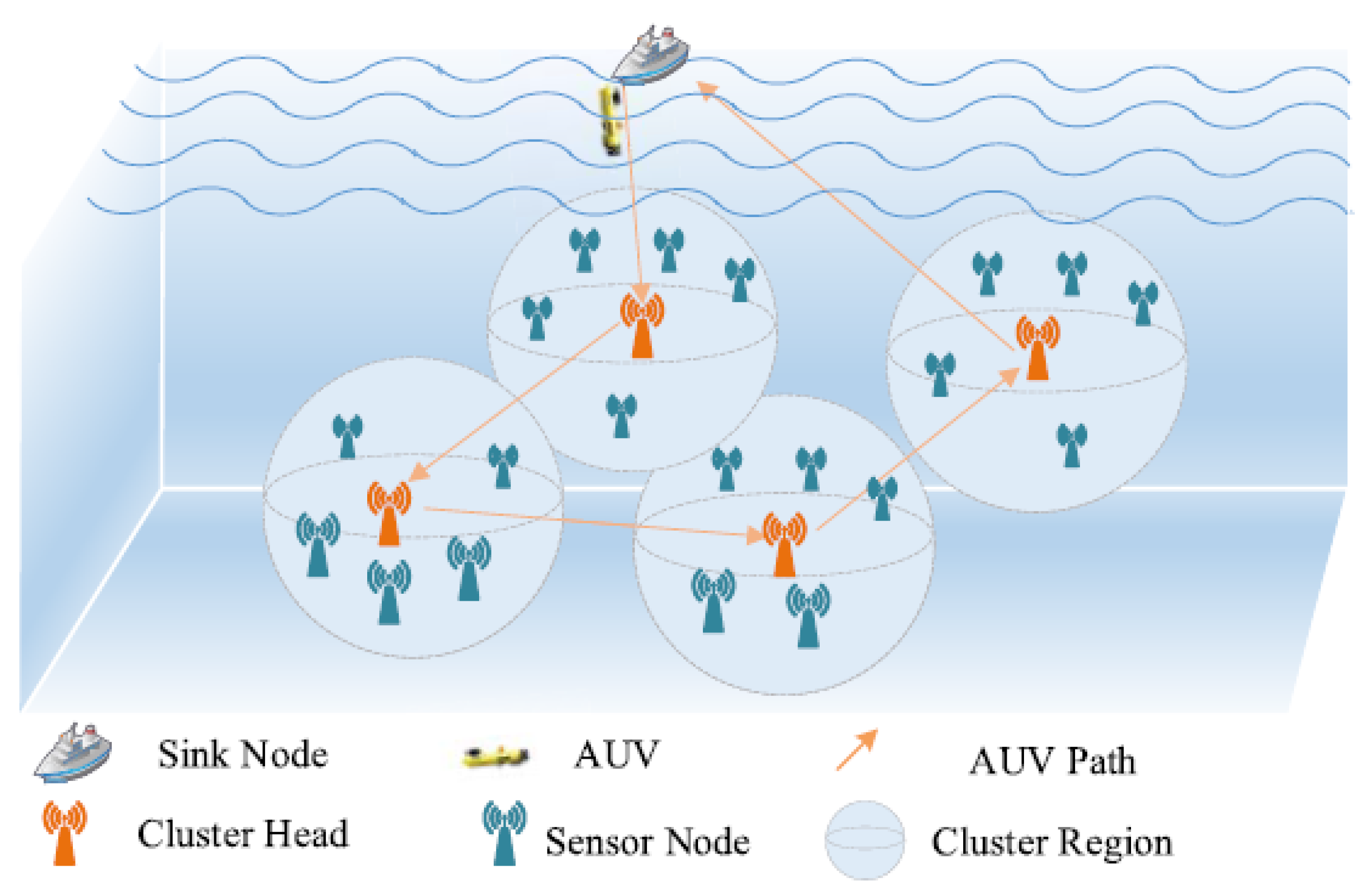
We consider a UWSN where N central nodes and several sensor nodes are deployed to provide monitoring of the underwater environment. The AUV sails around the central node to collect data and eventually offloads the collected data onto the surface station node (buoy or mothership). In this process, the AUV trajectory around the central node is the AUV’s cruise path. At the same time, the surface station node can transmit the data via marine wireless communication or satellite communication to the ground data center for further analysis and processing. We consider that the system is operated in a non-emergency situation, and the information collection process is repeated periodically. The network is mainly composed of three kinds of different types of nodes, as seen in Figure 1.

Figure 1.
Three-dimensional network model.
- Sensor Node: The function of the sensor node is to perform underwater surveillance tasks and send the monitored data to the central node to which it belongs. It is assumed that the sensor node is static in underwater environments, and sensor nodes are also constrained by limited battery resources because they are difficult to replace or charge. According to some time synchronization techniques [24] and positioning schemes [25], it is assumed that the sensor nodes are clock synchronized and the position of each sensor is known.
- Central Node: The central node as the data collection center in the cluster transmits the aggregated data to the AUV, so the central node has a high traffic load. If the central node continues to use underwater acoustic communication to transmit information, due to its high power consumption (the consumption of power for underwater acoustic communication is usually at the watt level [26]), the central node will soon die due to the exhaustion of its own limited battery energy, resulting in the entire network being paralyzed. In addition, because underwater acoustic communication has a limited data rate (tens of Kbps), the AUV needs to stay at the central node for a long time to wait for the data to be transmitted. The data collection scheme based on AUV can greatly reduce the data transmission distance of the central node. Therefore, in order to save the energy of the central node, improve the data transmission rate, and reduce the stagnation time of the AUV at the central node, optical communication with low latency, low power consumption, and high data rate (Gbps) [27] is chosen as the communication mode between the central node and the AUV.
- AUV: The role of the AUV is to obtain data from the central node by using high-speed optical communication and offload the collected data to the surface station. With the sinking of the AUV, long-distance data transmission is replaced by short-range communication, which not only reduces the energy consumption of underwater sensor nodes, but also makes it possible to apply underwater short-range and high-data-rate channels to transmit large amounts of data.
3.2. The Underwater Sensor Node Model
Assuming the surveillance area is divided into N clusters, each cluster contains a central node and several sensor nodes, and the sensor nodes are not evenly distributed in each cluster. The central node is labeled as , where is the central node collection; at the same time, the sensor node is called a child of the central node in its cluster. Without losing generality, assume that the cluster to which the central node n belongs contains sensor nodes. Each sensor node monitors the surroundings and sends the gathered data to the corresponding central node by means of direct communication (single-hop). Assuming that clusters are far apart, the intra-cluster communication will not be interfered with by other clusters. At the same time, the data transmission of the sensors in the cluster adopts multiple access control protocols based on CDMA to reduce the interference of the information transmission for other sensor nodes when the sensors send data to the central node.
Most of the existing work simplifies the process of sending data to the central node from the sensor node. The simple representation is that the AUV travels one round, and the central node receives a fixed amount of data. However, this is not consistent with the actual data transmission situation. In this paper, the data transmission process of the sensor node is controlled by the time scheduling policy. The sensor node periodically sends the data sensed during the time interval to the central node at a fixed time interval . The data collection rate of the child node i of the central node n is expressed by in Kbit per unit time. Considering that each sensor has different data collection capabilities and monitors different events in different areas, it is assumed that the data collection rate of each sensor node is not the same. The amount of data collected by sensor node i in the interval is , and then the collected data are sent to the corresponding central node n.
For ease of reading, the symbols used in this article and their meanings are listed in Glossary section.
3.3. AUV Model
When the AUV reaches a central node, an optical communication link is immediately established with the central node, the data in the central node are sent to the AUV through the optical link, and the AUV sails around the central node to repeat the data collection process. After completing data collection, the AUV makes its way back to the surface station to place the collected information at the surface station. The AUV as a dynamic relay node, the energy consumption, and the delay of AUV data collection are the main performance indexes of the whole sensor network.
The energy consumption of an AUV includes the energy consumed by moving along the central node, by establishing an optical communication link with the central node when reaching the central node, and the energy consumed by receiving data from the central node. It is assumed that when the AUV travels at speed to the central node n, the energy is consumed at the speed per unit distance, and the energy consumed for data sending and receiving is and per unit time, respectively. Then, the energy consumption of data collection in round t of the AUV can be calculated as:
where is the navigation energy expenditure in round t of the AUV. The expressions and , respectively, represent the total amount of data sent by AUV to central node n and the total amount of data sent by central node n to the AUV in round t. The data sent by the AUV to the central node are mainly concentrated in the communication link establishment stage, so the amount of data is the same for different cruise rounds and different central nodes. The data sent by the central node n to the AUV include the data of the communication link establishment stage and the data of the gathered underwater sensor nodes. The expressions and , respectively, represent the data transmission rate of central node n and the AUV; represents the central node set visited by the AUV in round t.
Data collection delay refers to the sum of the AUV’s flight delay and communication delay in a round of data acquisition. The time consumption of AUV in round t can be calculated as:
where represents the navigation time consumption of the AUV in round t. Because the central nodes and order of each round of AUV traversal are different, the energy and time consumed by each round of travel are also different.
In addition, and are chosen to represent the time when the AUV accessed the central node n twice before and twice after; the amount of data collected by central node n during this period is:
where , indicates round down. The value of the data gathered by the AUV during the navigation of round t is:
where is the data value decay function that is linearly dependent on time.
3.4. Problem Formulation
The aim of this paper is to maximize the data collection efficiency of the AUV by planning the cruise path of each AUV round while minimizing the energy consumption and time delay of the AUV.
Minimize the AUV’s time delay: According to Formula (2), AUV’s data collection delay is determined by the navigation delay of the AUV and the communication delay of the AUV, and the adoption of high data rate optical communication for data transmission will greatly reduce the data transmission delay. At the same time, as has been pointed out in [22], minimizing the navigation delay of the AUV is minimizing its time delay. Hence, there is:
Minimize the AUV’s energy consumption: The use of low-power optical communication can save the energy consumption of communication, so according to Formula (1), there is:
Therefore, the objective function of this paper is maximize the efficiency, which can be expressed as:
where and are both constant. They are the weight coefficients of energy consumption and time consumption, respectively, used to weigh the importance of energy consumption and time consumption.
4. AUV Dynamic Data Collection Based on DRL
The joint AUV path planning method based on DRL will be carefully demonstrated in this section, and the detailed improvement scheme of DRL will be given.
4.1. Reinforcement Learning
Reinforcement learning is a classic machine learning method. In reinforcement learning, the agent in state s interacts with the environment to get an estimate of its selected action a, which is a record of the reward value to guide the agent’s choice of future actions, and once the agent performs the action a, it will get the reward value r and move on to the next state . In the new state , the agent chooses actions either randomly or based on past learning experiences, and then receives a new reward value from the environment. This process is called reinforcement learning. As the cycle progresses, the agent learns from the action–reward experience to optimize its action selection strategy to adapt to the changing environment.
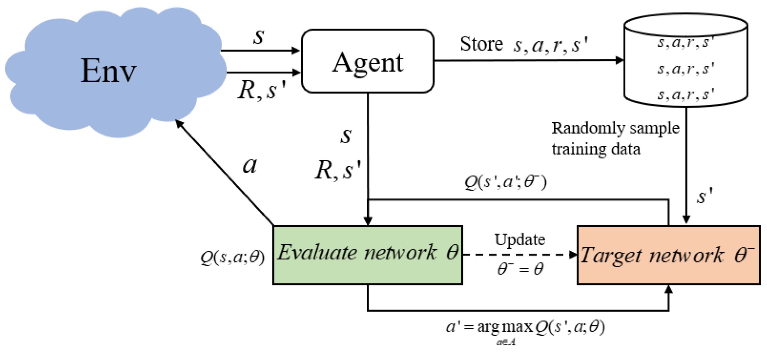
Double Deep Q Network (DDQN) [28] is a reinforcement learning method based on deep neural networks and is an extension of Deep Q Network (DQN) [29] used to solve the overestimation problem caused by the latter using the same network to evaluate and select actions. At the same time, the neural network is used to replace the Q table that stores the state-action Q value in the Q learning algorithm, so that reinforcement learning can be applied to more complex problems.
The two neural networks of DDQN, the current network and the target network, have the same structure, and the network parameters are , respectively. The current network is used to compute the estimated Q value and select the optimal action:
and obtain target Q through the target network:
therefore, the mean square error loss function (MSE) can be expressed as:
it is used to train the current network. Therefore, in DDQN, the updated equation of the action-value function is:
In the training process of DDQN, experience data are first stored in the experience playback pool, and then a certain amount of data are randomly extracted from it to build a loss function and update the network parameters based on the gradient descent strategy to make the loss function minimum and reduce the correlation between data. Figure 2 shows the overall structure of DDQN.
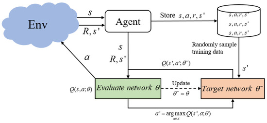
Figure 2.
The overall structure of DDQN.
4.2. The Proposed Strategy Based on DDQN
Representing the surface station node as a node numbered 0, the path planning problem for the AUV is similar to TSP, where the AUV’s journey always starts and ends at node 0 and contains a non-repeating sequence of central nodes. The cruise path of the AUV will directly affect the performance and efficiency of the system, and the AUV path should be carefully planned to maximize the efficiency of data collection of the AUV. The current practice is to take the path length as the main index to solve such problems, but for the actual AUV auxiliary data collection system, the node data information and the AUV state information will also have a great impact on the AUV path selection. Because the system is considered to operate in non-emergency situations, the AUV does not have to traverse all the central nodes on each cruise, in order to improve the data collection efficiency of the AUV.
The flight of an AUV can be characterized as a discrete-time Markov decision process (MDP) because the state of the AUV at slot is only related to the state at slot t. In order to get a good flight strategy, the AUV should not only consider the feedback of the next time slot, but also consider the long-term benefits when acting. Therefore, this paper intends to use DRL to plan the trajectory of the AUV by considering factors such as node location information, data information in nodes, and AUV status. After collecting the data in the current central node, the AUV first observes the current state , performs an action according to a specific strategy , and then receives an immediate reward . Reinforcement learning methods aim to make the agent find the optimal strategy to maximize the expected discount cumulative reward. The expected discount reward is also known as the Q function:
where is the attenuation factor reflecting the impact of future rewards. The larger the , the more the system focuses on future rewards. For problem P1, we propose the following reinforcement learning model:
- State: After the AUV has collected data from a central node, we define its observed state as:where presents the amount of data stored on all central nodes after the AUV collects data on the current central node.
- Action: After the AUV has collected data on the current central node, it will perform an action based on the state , which is the next node to traverse:where is the set of water surface station nodes and all central nodes; represents the nodes that have been traversed in the round t.In the existing work based on reinforcement learning, the method of giving negative punishment is usually used to prevent the agent from selecting invalid actions (such as the central node that has been traversed in each round in this paper). However, Ref. [30] proves that when the set of invalid actions is expanded, the ineffective action punishment method will not work, whereas the ineffective action masking method will complete the task well. With the continuous progress of the AUV cruise, the set of invalid actions (the nodes that have been traversed) keeps increasing, so this paper improves the strategy . The improved action selection strategy is shown in Algorithm 1, and Formula (8) of the current network to estimate Q value and select the optimal action is improved as follows:where represents a masking vector of invalid action in state .
- Reward: The reward function evaluates the action of the AUV’s choice in the state . For problem P1, the objective is to achieve efficient data collection, so the reward function can be defined as:where represents the reward for the AUV from the current node to the surface station node.
| Algorithm 1 Improved Action Selection Strategy |
| Input: Current State , AUV state . |
| Output: Next action a. |
|
The training process is summarized in Algorithm 2. It is important to note that the data of training the DNN network are obtained from the interaction of the AUV with the environment. The DDQN process consists of three main parts: the initialization part (line 1), the learning part (lines 11–18), and the update part (lines 19–28). The first part of the algorithm initializes the experience playback pool and two DNN networks to implement the experience playback and enhance the stability of the algorithm, respectively.
After initialization, the AUV begins to cruise around the central node. After collecting the data of the current central node, the AUV will observe the current state , that is, the amount of data stored in all the current central nodes, and then select an action according to Algorithm 1. By adopting improved strategy to select actions, the AUV can achieve a balance between exploration and development. At the beginning, set to a larger value to allow the AUV to explore the environment, and then gradually decrease as the algorithm converges. After performing the action , the AUV can receive a reward and move on to the next state . These experience data are packaged together with a symbol indicating whether the current state is a terminated state and stored in a tuple in a storage unit called the experience playback pool, which is used as a set of training data to train the network. As the AUV repeats data collection tasks, the number of tuples in the experience playback pool will continue to increase, and once the capacity of the experience playback pool is exceeded, new tuples will replace the previous tuples.
| Algorithm 2 The AUV Dynamic Data Collection Based on DDQN |
|
Finally, the DNN network is trained using a small batch tuple sampled from the experience playback pool. Specifically, and in each tuple will be fed to the current network and used to calculate the evaluated Q value. The target Q value (9) is calculated using and . The evaluated Q values and the target Q values will be used to calculate the loss function (10) and update the neuron weight parameters of the current network by implementing a gradient descent strategy on the loss function. At the same time, for every F network training time slot, the are copied from the current network to update the neuron weight parameters of the target network, that is, the parameter update of the target network lags behind the current network F steps, in order to reduce the correlation of Q functions at different times.
5. Simulation Analysis
Numerical simulation results are given in this section, with the aim of verifying the performance of the proposed method.
In the simulation, set the number of central nodes to . For DDQN, set the dimension of the input layer to 8, which is the same as the number of central nodes. The two hidden layers have 256 and 256 neurons, respectively, and use ReLu as an activation function. The dimension of the output layer is equal to the size of the action set, that is, the size of actions is 9. The AUV can choose not only the center node of the next cruise, but also the node of the return to the surface station, so the number of actions is 1 more than the number of center nodes. Adam is used as an optimizer. The information value of the central node is set as: , where [23]. At the same time, set the update frequency of , the update lag of the target network parameters, and take the average result of every rounds of cruise as the output result.
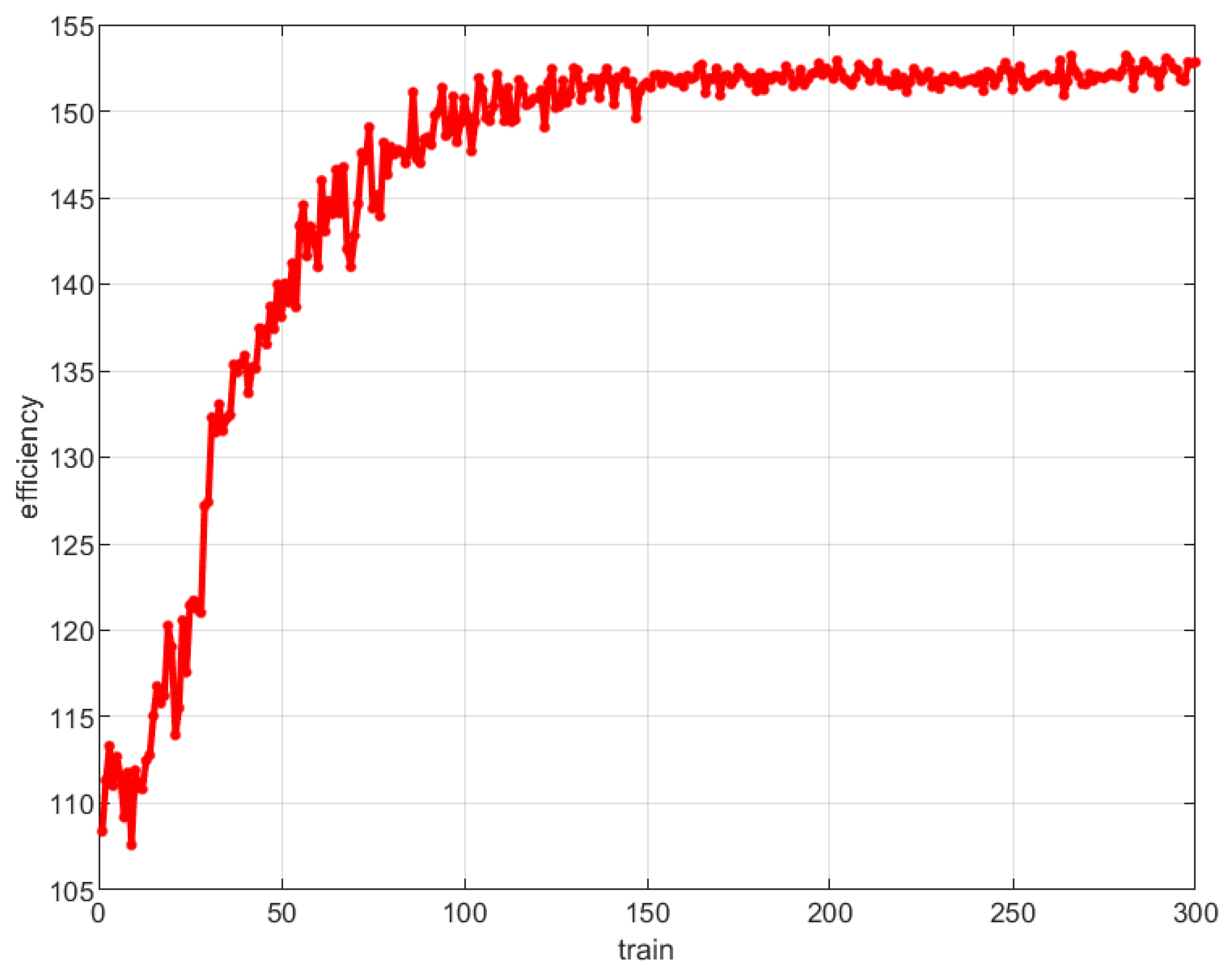
First, the convergence of the proposed method is analyzed, and the correlation between the efficiency of AUV data collection and the number of DRL iterations is shown in Figure 3. As shown in Figure 3, with the increase of the number of iterations, the data collection efficiency of AUV tends to be stable after about 10,000 trainings, that is, the algorithm gradually converges.
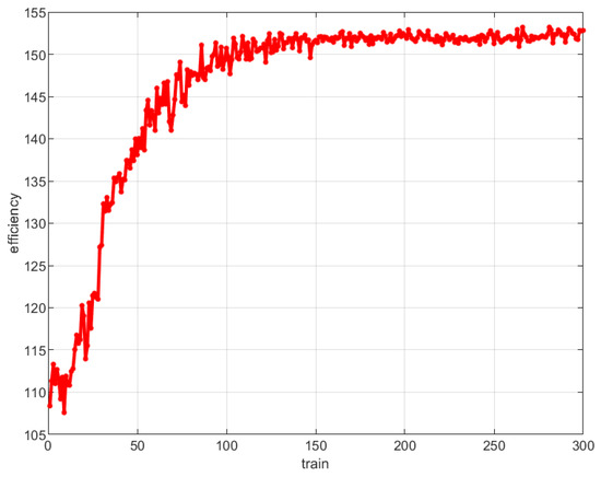
Figure 3.
Relationship between DRL training times and AUV data collection efficiency.
In order to evaluate the performance of the proposed methods, two comparison schemes are used in this paper. In the first scheme, the cruise path of the AUV is chosen by using the greedy method [19,22], that is, the AUV chooses the central node with the least travel cost as the target node every time, named Greedy. The second scheme is based on the genetic algorithm to obtain the AUV cruise path [21] and named Genetic. The proposed method is named DDQN-based.
Unlike the general TSP problem, the AUV’s cruise path always starts and ends at the surface station node (i.e., the node numbered 0). Therefore, when implementing the genetic algorithm in this paper, the chromosome structure is set as an arrangement of non-repeating numbers from 1 to N (where 1 to N are the numbers of N central nodes), but the navigation cost of sailing from the surface station node to the first gene and returning from the last gene to the surface station node needs to be added in the calculation of fitness function. In addition, this paper uses the roulette wheel selection method to select the best individual, the crossover algorithm is Partial-Mapped Crossover, the mutation algorithm is Inversion mutation, the crossover and mutation probabilities are set to 0.9 and 0.5, respectively, the population size is 60, and the number of generations of evolution is 100.
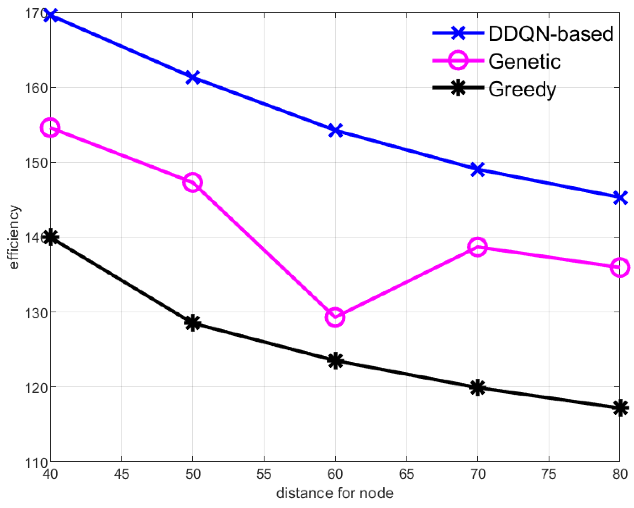
Figure 4 shows the data collection efficiency when the distance between central nodes increases. As the distance between nodes is increased, the efficiency of all schemes decreases, which is shown in Figure 4. The increase of distance means that the cruise of the AUV will take more time and energy. The amount of data gathered in the central node will also increase with the increase of cruise time; however, the growth rate of data value is less than the cost, so the efficiency of the AUV decreases. Among the four schemes, the method based on reinforcement learning has the highest efficiency, because the scheme can dynamically adjust the cruise path of each AUV round to achieve the maximum efficiency.
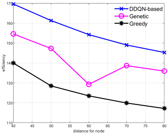
Figure 4.
Data collection efficiency of the AUV with different distances between center nodes.
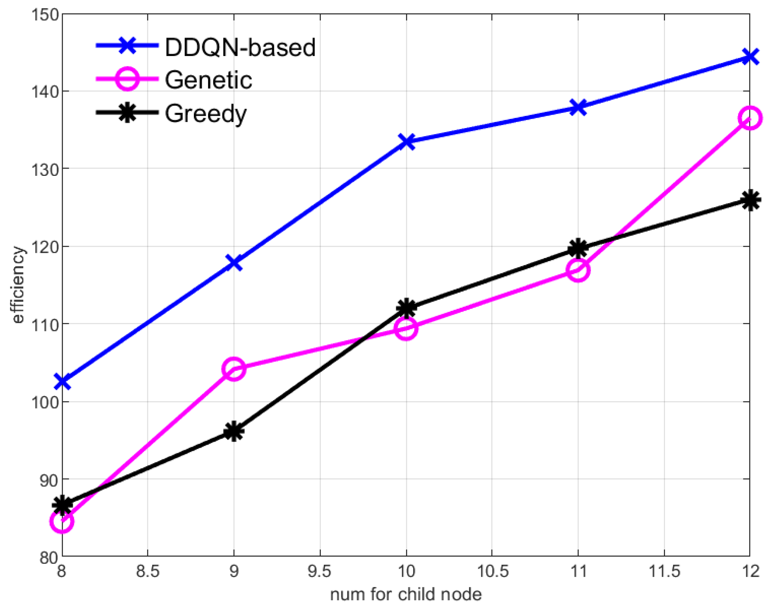
Figure 5 and Figure 6, respectively, show the data collection efficiency of the AUV when the data collection rate of sensor nodes increases and the number of sensor nodes increases. Both the increase in the data collection rate of the sensor nodes and the increase in the number of sensor nodes mean that the data aggregation rate in the central node increases, and the value of the data gained by the AUV from the central node increases, so the efficiency of the AUV increases. But methods based on reinforcement learning always have the highest efficiency.
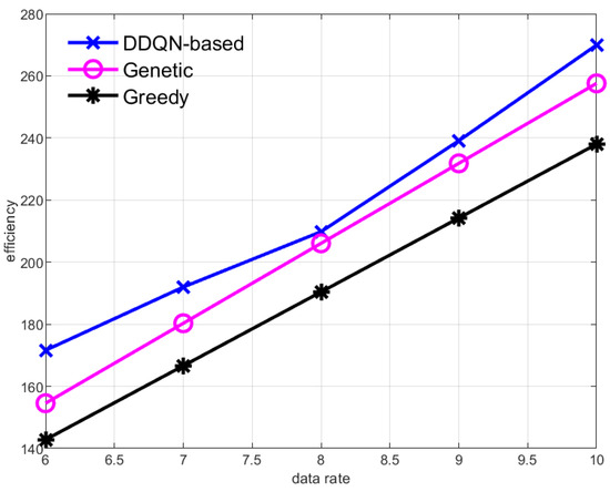
Figure 5.
Effect of changing the data collection rate of sub-sensor nodes on data collection efficiency of the AUV.
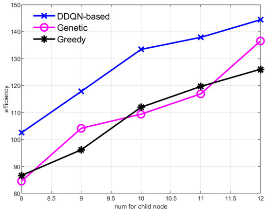
Figure 6.
The change of data collection efficiency of the AUV when the number of sub-sensor nodes changes.
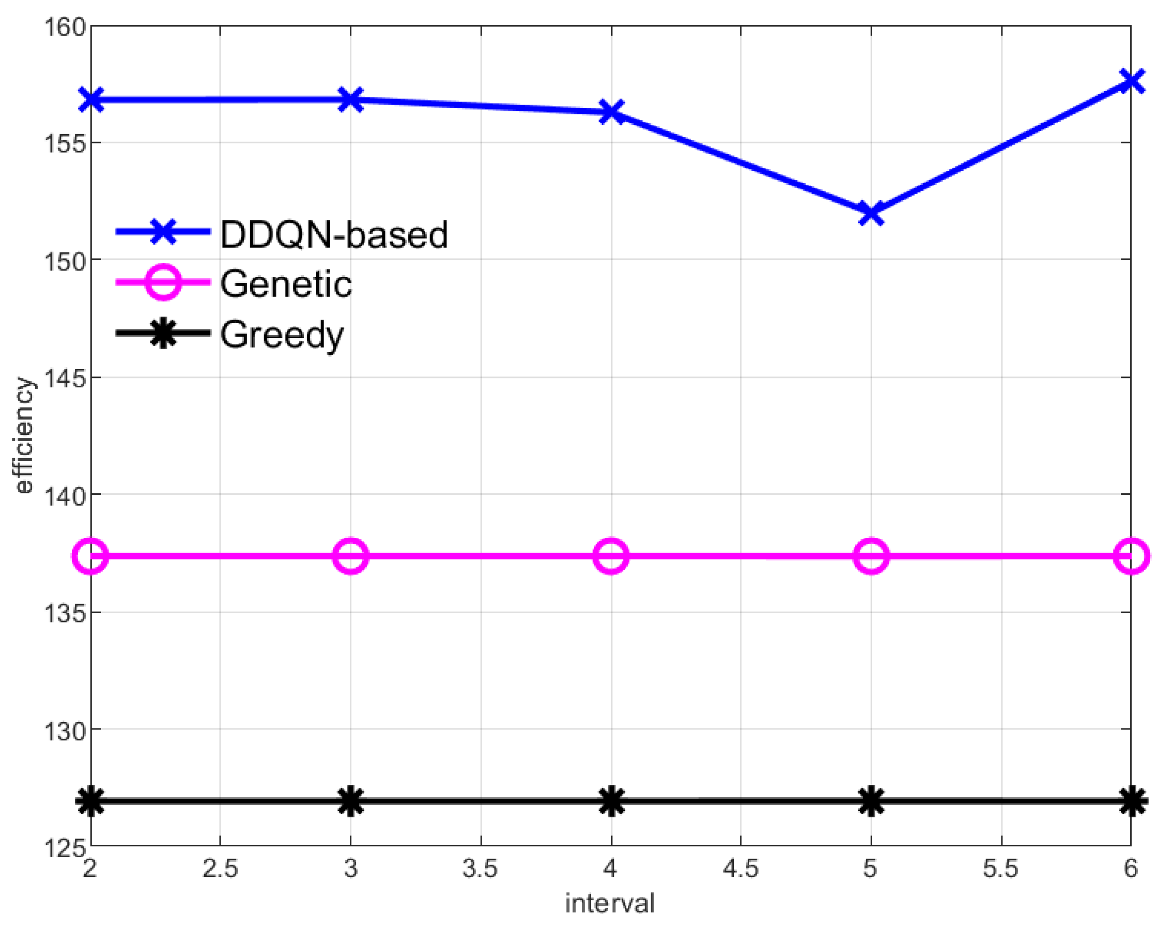
This paper also studies the data collection efficiency of the AUV at different data transmission intervals , as shown in Figure 7. Because the cruise path of the Genetic and Greedy algorithms is fixed each time, and the average results of every 100 rounds of cruise are displayed in this paper, the cruise cost and the amount of data collected by the AUV are constant, resulting in a straight line of data collection efficiency of the two methods. In the method proposed in this paper, the AUV cruise center node is a dynamic process, and the center node and the traversal order of each round are dynamically changed according to the environment, so the data collection efficiency will fluctuate under different transmission intervals . At the same time, because the AUV in the DDQN-based method can dynamically select the central node of traversal, its data collection efficiency is much higher than the other two methods.
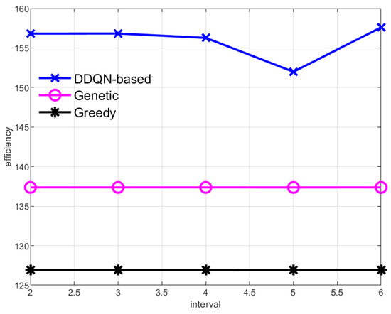
Figure 7.
Data collection efficiency of the AUV with different data transmission intervals.
6. Conclusions
In this paper, the dynamic planning of an AUV cruise path is studied, and a DRL-based AUV path planning scheme is proposed. Based on the realistic model, the AUV cruise path is dynamically planned by considering multiple dimensions, such as node location information, node VoI, and AUV state to maximize the efficiency of AUV data collection. The simulation results show that the proposed scheme is superior to the traditional path planning scheme that only considers the node location and can greatly improve the efficiency of AUV data collection. Although this paper provides an effective data collection scheme for underwater sensor networks, the work in this paper still has limitations and needs further research. First of all, the AUV is actually a robot with six degrees of freedom, its movement is complex, the AUV in motion has a huge moment of inertia, and it needs to consume a lot of energy to change the direction of movement. Therefore, the path planning that fully considers its six degrees of freedom needs further study. Second, due to cost, personnel, and other limitations, this paper only conducted simulation verification at the theoretical level, without underwater experiment verification. Real underwater experiments are very important for the validation and improvement of models and algorithms. Therefore, if the scheme proposed in this paper is to be applied to the actual underwater sensor network data collection task, further off-site experiments are necessary.
Author Contributions
Conceptualization, L.J. and Y.T.; formal analysis, L.J.; methodology, L.J. and W.S.; software, Y.T. and M.J.; validation, W.S.; writing—original draft, W.S.; writing—review and editing, L.J. and M.J.; visualization, L.J. and Y.T.; supervision, W.S. and L.J.; project administration, L.J. and W.S.; funding acquisition, L.J. and W.S. All authors have read and agreed to the published version of the manuscript.
Funding
This work was supported by the National Natural Science Foundation of China (62371393, 62071383) and the Fundamental Research Funds for the Central Universities (23GH02027).
Institutional Review Board Statement
Not applicable.
Informed Consent Statement
Not applicable.
Data Availability Statement
The data presented in this paper are available by contacting the corresponding author.
Acknowledgments
The authors would like to thank the anonymous reviewers for their careful reading and valuable comments.
Conflicts of Interest
The authors declare no conflict of interest.
Glossary
The following abbreviations are used in this manuscript:
| Symbol | Implication |
| n | The number of central nodes. |
| The set of the central nodes. | |
| The number of the child nodes contained by the central node n. | |
| The data transmission interval of the sensor nodes. | |
| The data collection rate of child node I of central node n. | |
| The energy expenditure of round t of the AUV. | |
| The navigation energy expenditure of round t of the AUV. | |
| The time spent on round t of the AUV. | |
| The navigation time spent on round t of the AUV. | |
| The value of the data collected at round t. |
References
- Zhu, J.; Pan, X.; Peng, Z.; Liu, M.; Guo, J.; Zhang, T.; Gou, Y.; Cui, J.-H. A uw-cellular network: Design, implementation and experiments. J. Mar. Sci. Eng. 2023, 11, 827. [Google Scholar] [CrossRef]
- Pan, X.; Zhu, J.; Liu, M.; Wang, X.; Peng, Z.; Liu, J.; Cui, J. An on-demand scheduling-based mac protocol for uw-wifi networks. J. Mar. Sci. Eng. 2023, 11, 765. [Google Scholar] [CrossRef]
- Razzaq, A.; Mohsan, S.A.H.; Li, Y.; Alsharif, M.H. Architectural framework for underwater iot: Forecasting system for analyzing oceanographic data and observing the environment. J. Mar. Sci. Eng. 2023, 11, 368. [Google Scholar] [CrossRef]
- Li, Y.; Bai, J.; Chen, Y.; Lu, X.; Jing, P. High value of information guided data enhancement for heterogeneous underwater wireless sensor networks. J. Mar. Sci. Eng. 2023, 11, 1654. [Google Scholar] [CrossRef]
- Kabanov, A.; Kramar, V. Marine internet of things platforms for interoperability of marine robotic agents: An overview of concepts and architectures. J. Mar. Sci. Eng. 2022, 10, 1279. [Google Scholar] [CrossRef]
- Glaviano, F.; Esposito, R.; Cosmo, A.D.; Esposito, F.; Gerevini, L.; Ria, A.; Molinara, M.; Bruschi, P.; Costantini, M.; Zupo, V. Management and sustainable exploitation of marine environments through smart monitoring and automation. J. Mar. Sci. Eng. 2022, 10, 297. [Google Scholar] [CrossRef]
- Mohsan, S.A.H.; Li, Y.; Sadiq, M.; Liang, J.; Khan, M.A. Recent advances, future trends, applications and challenges of internet of underwater things (iout): A comprehensive review. J. Mar. Sci. Eng. 2023, 11, 124. [Google Scholar] [CrossRef]
- Du, J.; Gelenbe, E.; Jiang, C.; Zhang, H.; Ren, Y. Contract design for traffic offloading and resource allocation in heterogeneous ultra-dense networks. IEEE J. Sel. Areas Commun. 2017, 35, 2457–2467. [Google Scholar] [CrossRef]
- Yoon, S.; Qiao, C. Cooperative search and survey using autonomous underwater vehicles (auvs). IEEE Trans. Parallel Distrib. Syst. 2011, 22, 364–379. [Google Scholar] [CrossRef]
- Qiu, T.; Zhao, Z.; Zhang, T.; Chen, C.; Chen, C.L.P. Underwater internet of things in smart ocean: System architecture and open issues. IEEE Trans. Ind. Inform. 2020, 16, 4297–4307. [Google Scholar] [CrossRef]
- Liu, L.; Zhang, N.; Liu, Y. Topology control models and solutions for signal irregularity in mobile underwater wireless sensor networks. J. Netw. Comput. Appl. 2015, 51, 68–90. [Google Scholar] [CrossRef]
- Jurdak, R.; Lopes, C.; Baldi, P. Battery lifetime estimation and optimization for underwater sensor networks. IEEE Sens. Netw. Oper. 2004, 2006, 397–420. [Google Scholar]
- Yoon, S.; Azad, A.K.; Oh, H.; Kim, S. Aurp: An auv-aided underwater routing protocol for underwater acoustic sensor networks. Sensors 2012, 12, 1827–1845. [Google Scholar] [CrossRef] [PubMed]
- Ahmad, A.; Wahid, A.; Kim, D. Aeerp: Auv aided energy efficient routing protocol for underwater acoustic sensor network. In Proceedings of the 8th ACM Workshop on Performance Monitoring and Measurement of Heterogeneous Wireless and Wired Networks, New York, NY, USA, 3–8 November 2013; pp. 53–60. [Google Scholar]
- Ilyas, N.; Alghamdi, T.A.; Farooq, M.N.; Mehboob, B.; Sadiq, A.H.; Qasim, U.; Khan, Z.A.; Javaid, N. Aedg: Auv-aided efficient data gathering routing protocol for underwater wireless sensor networks. Procedia Comput. Sci. 2015, 52, 568–575. [Google Scholar] [CrossRef]
- Wang, X.; Wei, D.; Wei, X.; Cui, J.; Pan, M. Has4: A heuristic adaptive sink sensor set selection for underwater auv-aid data gathering algorithm. Sensors 2018, 18, 4110. [Google Scholar] [CrossRef] [PubMed]
- Qin, C.; Du, J.; Wang, J.; Ren, Y. A hierarchical information acquisition system for auv assisted internet of underwater things. IEEE Access 2020, 8, 176089–176100. [Google Scholar] [CrossRef]
- Han, G.; Shen, S.; Song, H.; Yang, T.; Zhang, W. A stratification-based data collection scheme in underwater acoustic sensor networks. IEEE Trans. Veh. Technol. 2018, 67, 10671–10682. [Google Scholar] [CrossRef]
- Huang, M.; Zhang, K.; Zeng, Z.; Wang, T.; Liu, Y. An auv-assisted data gathering scheme based on clustering and matrix completion for smart ocean. IEEE Internet Things J. 2020, 7, 9904–9918. [Google Scholar] [CrossRef]
- Zhuo, X.; Liu, M.; Wei, Y.; Yu, G.; Qu, F.; Sun, R. Auv-aided energy-efficient data collection in underwater acoustic sensor networks. IEEE Internet Things J. 2020, 7, 10010–10022. [Google Scholar] [CrossRef]
- Liu, Z.; Meng, X.; Liu, Y.; Yang, Y.; Wang, Y. Auv-aided hybrid data collection scheme based on value of information for internet of underwater things. IEEE Internet Things J. 2022, 9, 6944–6955. [Google Scholar] [CrossRef]
- Cai, S.; Zhu, Y.; Wang, T.; Xu, G.; Liu, A.; Liu, X. Data collection in underwater sensor networks based on mobile edge computing. IEEE Access 2019, 7, 65357–65367. [Google Scholar] [CrossRef]
- Yan, J.; Yang, X.; Luo, X.; Chen, C. Energy-efficient data collection over auv-assisted underwater acoustic sensor network. IEEE Syst. J. 2018, 12, 3519–3530. [Google Scholar] [CrossRef]
- Liu, J.; Wang, Z.; Zuba, M.; Peng, Z.; Cui, J.-H.; Zhou, S. Da-sync: A doppler-assisted time-synchronization scheme for mobile underwater sensor networks. IEEE Trans. Mob. Comput. 2014, 13, 582–595. [Google Scholar] [CrossRef]
- Yan, J.; Xu, Z.; Wan, Y.; Chen, C.; Luo, X. Consensus estimation-based target localization in underwater acoustic sensor networks. Int. J. Robust Nonlinear Control. 2017, 27, 1607–1627. [Google Scholar] [CrossRef]
- Wei, D.; Huang, C.; Li, X.; Lin, B.; Shu, M.; Wang, J.; Pan, M. Power-efficient data collection scheme for auv-assisted magnetic induction and acoustic hybrid internet of underwater things. IEEE Internet Things J. 2022, 9, 11675–11684. [Google Scholar] [CrossRef]
- Lv, Z.; He, G.; Qiu, C.; Liu, Z. Investigation of underwater wireless optical communications links with surface currents and tides for oceanic signal transmission. IEEE Photonics J. 2021, 13, 1–8. [Google Scholar] [CrossRef]
- Zhu, Z.; Hu, C.; Zhu, C.; Zhu, Y.; Sheng, Y. An improved dueling deep double-q network based on prioritized experience replay for path planning of unmanned surface vehicles. J. Mar. Sci. Eng. 2021, 9, 1267. [Google Scholar] [CrossRef]
- Xing, B.; Wang, X.; Yang, L.; Liu, Z.; Wu, Q. An algorithm of complete coverage path planning for unmanned surface vehicle based on reinforcement learning. J. Mar. Sci. Eng. 2023, 11, 645. [Google Scholar] [CrossRef]
- Huang, S.; Onta nón, S. A closer look at invalid action masking in policy gradient algorithms. arXiv 2022, arXiv:200614171. [Google Scholar] [CrossRef]

Disclaimer/Publisher’s Note: The statements, opinions and data contained in all publications are solely those of the individual author(s) and contributor(s) and not of MDPI and/or the editor(s). MDPI and/or the editor(s) disclaim responsibility for any injury to people or property resulting from any ideas, methods, instructions or products referred to in the content. |
© 2023 by the authors. Licensee MDPI, Basel, Switzerland. This article is an open access article distributed under the terms and conditions of the Creative Commons Attribution (CC BY) license (https://creativecommons.org/licenses/by/4.0/).