Article

Performance Analysis of a WPCN-Based Underwater Acoustic Communication System

School of Electronic and Information Engineering, South China University of Technology, Guangzhou 510641, China
*
Author to whom correspondence should be addressed.
J. Mar. Sci. Eng. 2024, 12(1), 43; https://doi.org/10.3390/jmse12010043
Submission received: 7 November 2023 / Revised: 16 December 2023 / Accepted: 21 December 2023 / Published: 23 December 2023
(This article belongs to the Special Issue Underwater Wireless Communications: Recent Advances and Challenges)

Abstract

:
Underwater acoustic communication (UWAC) has a wide range of applications, including marine environment monitoring, disaster warning, seabed terrain exploration, and oil extraction. It plays an indispensable and increasingly important role in marine resource exploration and marine economic development. In current UWAC systems, the terminal nodes are usually powered by energy-limited batteries. Due to the harshness of the underwater environment, especially in the ocean environment, it is very costly and difficult, even impossible, to replace the batteries for the terminal nodes in UWACs, which results in the short lifetime and unreliability of the terminal nodes and the systems. In this paper, we present the application of a wireless powered communication network (WPCN) to the UWAC systems to provide an auxiliary and convenient energy supplement for solving the energy-limited problem of the terminal nodes, where the hybrid access point (H-AP) transfers energy to the terminal nodes in the downlink. In contrast, the terminal nodes use the harvested energy to transmit the information to the H-AP in the uplink. To evaluate the proposed WPCN-based UWAC systems, we investigate the performance of the average bit error rate (BER), outage probability, and achievable information rate for the systems in a frequency-selective sparse channel and non-white noise environment. We derive the closed-form expression for the probability density function (PDF) of the received signal-to-noise ratio (SNR). Based on this, we further derive novel closed-form expressions for the average BER and the outage probability of the systems. Numerical results confirm the validity of the proposed analytical results. It is shown that there exists an optimal signal frequency and time allocation factor for the systems to achieve optimal performance, and a larger optimal time allocation factor is preferred for a smaller hybrid access point (H-AP) transmit power or a larger transmission distance, while a smaller optimal signal frequency is required for a larger transmission distance.

1. Introduction

Underwater acoustic communication (UWAC) using acoustic waves as the carrier can realize long-distance information transmission in the underwater environment. UWAC is considered to be the best choice and mainstream technology for underwater communications so far and for a long time to come. As shown in Figure 1, a typical UWAC system usually consists of sensor nodes, underwater vehicles, and communication buoys. The sensor nodes are responsible for sensing the underwater environment and collecting data. The underwater vehicles, which include submarines, autonomous underwater vehicles (AUVs), and remotely operated vehicles, are used for various tasks such as surveillance, exploration, maintenance, or intermediate nodes for relaying communication signals between the sensor nodes and the communication buoys. The communication buoys serve as the gateway nodes to interconnect underwater sensor networks with other networks through wireless communication.
UWAC systems comprising static sensors and underwater vehicles have been applied to many scenarios, such as undersea oil exploration, environmental monitoring, and coastal surveillance [1]. However, due to the harshness of the underwater environment, the development of UWAC systems has encountered many obstacles, including the energy limitation of the terminal nodes [2]. Underwater terminal nodes, such as sensors, are usually equipped with energy-constrained batteries. Since manually replacing batteries is very costly and even impossible in the harsh underwater environment, underwater terminal nodes can usually only work for a short period of time, which leads to an unsatisfactory lifetime and reliability of the UWAC systems, as well as significant resource waste. Developing an efficient and sustainable energy supply for the energy-limited terminals has become an urgent issue for the UWAC systems.
Wireless powered communication network (WPCN) is one of the most attractable and promising energy supplement technologies that allows energy-limited terminals to harvest energy from the energy sources and ambient environment to prolong the lifetime and reliability of the terminals [3]. In WPCNs, the hybrid access point (H-AP) transfers energy to the energy-limited terminals in the downlink, while in the uplink, the terminals use the harvested energy to transfer information to the H-AP. With the tunable transmit power, waveform, frequency, etc., of the energy signals of H-AP, WPCN can provide stable, comparably controllable, and self-sustainable power supplies and eliminate the need for manual battery recharging/replacement, thus having a wide range of application perspectives in extreme environments such as underwater, body of area networks, etc. [4,5]. Moreover, WPCN can realize the joint optimization design of downlink energy transmission/harvesting and uplink wireless information transmission to obtain optimal resource allocation and realize optimal use of wireless resources and network infrastructure [5]. WPCN is particularly suitable for the application fields of underwater acoustic sensing networks, such as offshore oil extraction monitoring and marine environmental monitoring. In these applications, the underwater acoustic sensors require extremely high reliability and a long service lifetime, while only needing to transmit a few data bits per hour; hence, WPCN can meet the power consumption requirement of the sensors [6]. For example, assuming that the transmitted acoustic power of the energy transmitter (base station/access point, buoy, etc.) is P t s = 50   W , considering that the carrier frequency f = 15 kHz , transmission distance d = 0.5 km , spreading factor m = 1.5 , and transducer directivity D I = 10 dB , the signal sound pressure level (SPL) received at the destination node can be calculated as S P L = 170.8 + 10 log 10 ( P t s ) + D I T L = 156.1   dB   re   μ Pa , where TL is the acoustic path loss given in dB that can be calculated using Equation (3) in Section 2.3. Then an amount of about 23 mW of output power can be harvested at the receiver with a proper EH circuit for the terminal node [6,7].

1.1. Related Work

UWAC began in World War II and has a long history. However, due to the harshness of the underwater environments and channels, it has been difficult to realize and develop underwater communications, especially before the 1990s of the last century. Since the end of the last century, researchers from various countries have successively applied various signal processing technologies in terrestrial wireless electromagnetic wave communication to UWAC systems, achieving rich results, and the theories and technologies of UWAC have been developed rapidly [8,9,10,11,12,13,14,15,16,17,18,19,20], where the research in [8,9,10,11,12] studied physical layer signal transmission and processing technology, the studies in [13,14,15,16] exploited medium access control (MAC) layer and routing protocol, and the authors in [17,18,19,20] investigated the experiment and application of UWAC networking. Specifically, in [8,9], orthogonal frequency division multiplexing (OFDM) modulation was applied to the UWAC to counter inter-symbol interference. In [10,11], the authors introduced relay nodes to the UWAC system to improve transmission reliability and reduce power consumption, while in [12], multiple-input multiple-output (MIMO) technology was applied to improve the transmission rate. In [13,14], the authors summarized the challenges in designing underwater MAC protocols from different perspectives. The authors of [15] proposed the Integrated Secure MAC principle and Long Short-Term Memory architecture for organizing real-time neighbor monitoring tasks to protect the data. A non-orthogonal multiple access (NOMA)-based MAC protocol was proposed in [16] to achieve efficient underwater concurrent communications and high capacity. In [17], the concept of “Seaweb” was first proposed, and [18] briefly described the typical communication architecture of an underwater network. The development of a protocol stack for self-reconfigurable UWAC systems that autonomously adapt to changing environmental conditions and operational needs was reported by the European Defense Agency [19]. In [20], the authors designed and expounded on a set of UWAC systems and signal processing systems that effectively ensure the stability and simplicity of the data transmission process. The above works mainly focus on communication performance, including bit error rate (BER), outage probability, and data rate, whereas the energy limitation issues are not concerned.
With the rapid development of UWAC network theory and technology, the problem of energy limitation and the resulting short lifetime of underwater terminal nodes has attracted growing attention [21,22,23,24,25]. In particular, the Monterey Bay Aquarium Research Institute designed a portable mooring system that can collect solar and wind energy to provide power for shore-side terminal nodes [21]. In [22], the authors studied the energy efficiency performance of a three-node underwater full-duplex relay network, where the relay can harvest energy from the ambient environment. To provide a reference for realizing efficient and flexible energy supply for autonomous underwater vehicles (AUVs), the authors in [23] analyzed several effective methods to reduce the high energy loss during underwater wireless power transfer, including coupling mechanism optimization, adaptive control, and docking device design. In [24], to solve the energy supply problem of AUVs, the authors proposed a novel “ID”-shaped magnetic coupler with a pendulum-type receiver, which has characteristics of compact structure, lightweight, and high receiver power density. In [25], the authors summarized the energy optimization techniques in underwater communication networks proposed in recent years, including a power-efficient routing protocol [26], an efficiency reservation MAC protocol [27], etc. In [28], the authors designed a batteryless underwater sensor node that can be wirelessly recharged through ultrasonic waves and validated that the harvested energy was sufficient to meet the requirement of power consumption through experiments. In [29], three-dimensional acoustic and electric conversion channels based on an ultrasonic transducer array were constructed, and an effective method for an array amplitude weighting algorithm was proposed to achieve efficient underwater wireless energy transmission. Despite the realization of wireless power transfer in the underwater environment, these works have their drawbacks and disadvantages. Specifically, the methods proposed in [21,22] involve harvesting energy from natural energy sources, which depends on weather and other natural environments, resulting in the instability, uncontrollability, and unreliability of the energy harvesting, as well as difficulties in hardware implementation in marine environments. The scheme proposed in [24] is highly susceptible to the influence of the marine environment (such as ocean currents and seawater temperature) and can only operate within millimeter-level distances. Similarly, the wireless power transfer methods in [28,29] can only operate within a distance of a few meters.
As a promising wireless power transfer technology, WPCN has attracted notable and growing interest since Varshney first proposed the concept of transporting information and energy simultaneously [30]. In [31], the authors proposed a dynamic power-splitting receiver where the received signal was split with an adjustable power ratio for energy harvesting and information decoding separately. In [32,33,34], different schemes were proposed to enhance the performance of the WPCN systems in different channels and scenarios. Specifically, joint optimization of downlink wireless power transfer (WPT), uplink wireless information transfer (WIT), and power allocation in the Rayleigh channel have been studied in [32] to acquire the maximum information rate and balanced throughput. In [33], the same optimization problem as [32] was analyzed in the Nakagami-m channel. In [34], the intelligent reflecting surface (IRS) was introduced to the full-duplex (FD) WPCN to enhance the performance of the system, where an FD hybrid node sends information in the downlink and receives energy signals in the uplink simultaneously. Meanwhile, different WPCN protocols have also been studied in [3,35], where the authors proposed a “harvest then transmit” protocol and derived an optimal time allocation parameter for throughput maximization in [3], while in [33], the authors proposed a “transfer then receive” protocol for the WPCN system based on time division multiple access (TDMA) and analyzed the throughput maximization for the system.

1.2. Motivation and Contributions

So far, the research on UWAC systems still focuses on improving the communication qualities of the system, such as communication reliability, information transmission rate, communication distance, coverage, etc., while the research on how to solve the energy-limited problem of the nodes in UWAC systems is rather insufficient. WPCN is a promising and attractive scheme for the energy-limited problem of underwater acoustic nodes in UWAC systems. As shown in Figure 1, by applying the WPCN technology to UWAC systems, underwater vehicles with sufficient power supply can serve as energy replenishment devices for long-distance energy transfer to the sensor nodes in the downlink. The sensor nodes can harvest the energy and use it to transmit information to the underwater vehicles in the uplink. Compared to the current power transfer schemes that can only operate within a few meters [28,29] or are environmentally susceptible and unreliable [21,22,24], a WPCN-based UWAC system can stably and comparably controllably power the sensor nodes at a much farther distance of hundreds or even thousands of meters.
Motivated by the above observations, in this paper, we present the application of WPCN to the UWAC systems and investigate the performance of the WPCN-based UWAC systems. To the best knowledge of the authors, except for the work of [6], where an overview was provided for the wireless information and power transfer (WIPT)-based UWAC and networks, there is no other research on the WPCN-based UWAC systems. Our main contributions are as follows:
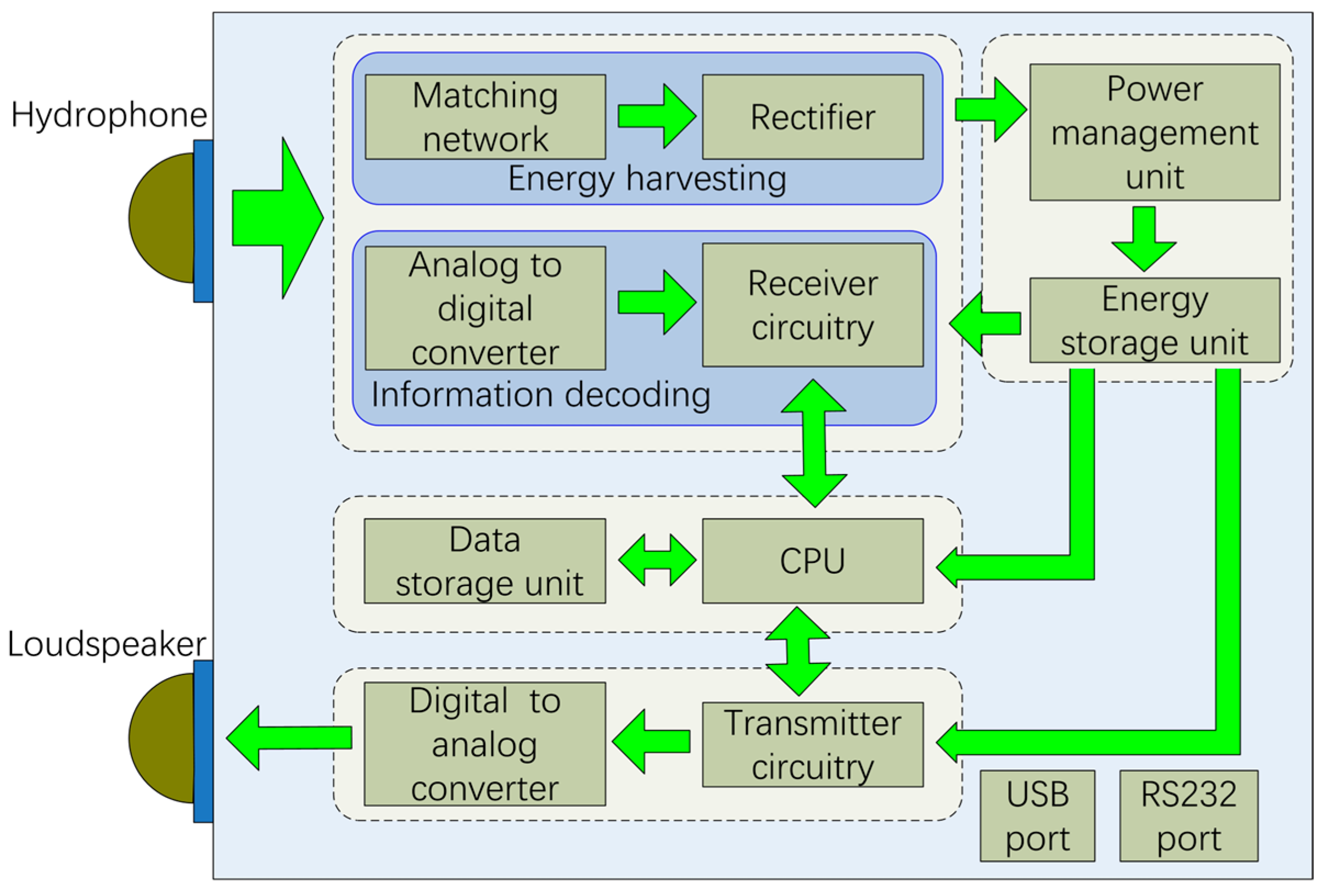
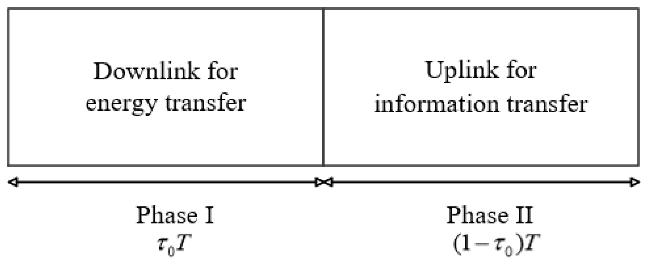
  • We present an application of WPCN to the UWAC systems to provide an auxiliary and convenient energy supplement for solving the energy-limited problem of underwater acoustic nodes, where the H-AP transfers energy to the terminal node in the downlink while the hydrophone of the terminal node exploits the received acoustical signal and ambient noise for energy harvesting. The harvested energy at the terminal node is then used for the information transmission in the uplink;
  • We analyze the average BER, outage probability, and achievable rate performance for the WPCN-based UWAC systems in the frequency-selective sparse channel and non-white noise environments. We first derive the closed-form expression for the probability density function (PDF) of the received signal-to-noise ratio (SNR) at the H-AP in the uplink. Based on this, we further derive closed-form expressions of the average BER and outage probability of the systems, which are used in the discussion for the effects of system and channel parameters on the system performance;
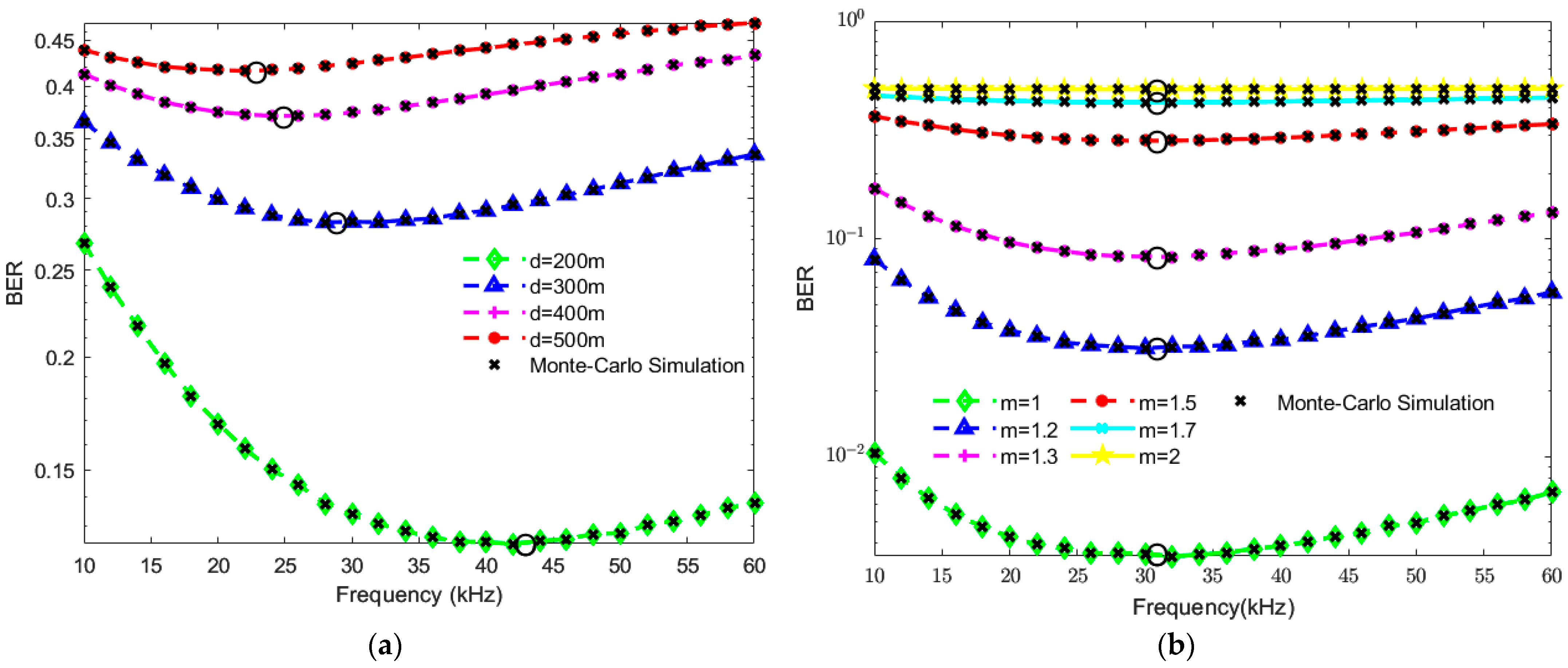
  • We investigate the impacts of the transmission distance, signal frequency, spreading factor, and time allocation factor on the system’s performance. It is demonstrated that there exist optimal signal frequency and time allocation factors to minimize the average BER and maximize the achievable information rate for the system, respectively. Moreover, a larger optimal time allocation factor is preferred for a smaller H-AP transmit power or a larger transmission distance, while a smaller optimal signal frequency is required for a larger transmission distance.
The rest of the paper is organized as follows. In Section 2, we present and introduce the model of the WPCN-based UWAC system. In Section 3, the performance of the system in terms of the average BER and the outage probability is analyzed. In Section 4, the analytical and simulation results, along with the discussion, are presented. Finally, the conclusion is given in Section 5.

2. System Model

We consider a point-to-point WPCN-based UWAC system consisting of one H-AP and one terminal node. Both H-AP and terminal nodes are equipped with one single hydrophone and loudspeaker pair.

2.1. Hardware Architecture of the WPCN-Based Underwater Acoustic Terminal Node

As shown in Figure 2, the WPCN-based underwater acoustic terminal node consists of the antenna module, receiving module, power module, processing module, transmitting module, and data ports. Specifically, the antenna module consists of a hydrophone and a loudspeaker. The receiving module includes the energy harvesting (EH) unit and the information decoding (ID) unit. The EH unit consists of a matching network and a rectifier, which is an essential block for the implementation of WPT. The EH unit converts the output voltage energy of the hydrophone into direct current (DC) electricity for energy scavenging and then inputs the harvested energy to the power module for battery charging. The power module consists of a power management unit and an energy storage unit, where the energy storage unit is usually a rechargeable battery plus a supercapacitor. The processing module consists of a small center processing unit (CPU) and a data storage unit, where the data storage unit is usually a memory card. The transmission module consists of transmitter circuitry and a digital-to-analog converter. The data ports, usually USB or RS232 ports, are used for stored data download from or programming the device and provide the interface for the sensors.
For more details, an example of the representation of hardware devices, along with their specifications used in the design, is given as follows. A duty circuit, including a voltage comparator, an electric relay, and a microcontrol unit, determines whether the received signal is an energy signal or an information signal, and based on this, sends the signal to the ID or EH circuit. The receiver circuitry of the ID unit includes an automatic gain amplifier circuit based on chip VCA810 and instrumentation amplifier INA828, a filter based on the RS722XK operational amplifier, and a voltage follower based on the RS721XM operational amplifier, which is used to decode the information signal. The rectifier circuit of the EH unit adopts a voltage-doubling circuit with the BAT54S diode as the core, which converts the input alternating current (AC) signal into DC and outputs it to the power module. The power management unit is based on the BQ25504 chip, which increases the low voltage output of the rectifier circuit to a high voltage and outputs it to the energy storage unit. The CPU adopts a STM32F103ZET6 processor. The transmitter circuit consists of a signal generator AD9850 chip and a power amplifier IRS2092S chip, where the initial data can be converted into an electrical signal by the signal generator and amplified by the power amplifier.

2.2. Transmit Protocol

The system adopts a harvest-then-transmit protocol as shown in Figure 3, where the transmission of each communication block is divided into two-time phases, i.e., phase I and phase II. In phase I, the H-AP transfers power to the terminal node in the downlink with a time duration of τ 0 T , where T is the transmission time of each communication block and τ 0 0 τ 0 1 is the time allocation factor. In phase II, the terminal node uses the harvested energy to transmit information data to the H-AP in the uplink with a time duration of ( 1 τ 0 ) T . To effectively counter the inter-symbol interference caused by multipath fading, the OFDM modulation scheme is applied to the system.

2.3. Channel Model

We assume frequency-selective, sparse channels for underwater acoustic links. These channels are modeled by a tapped delay line (TDL) with the order of L [36]. Let h = h ( 1 ) , 0 , , 0 , h ( 2 ) , 0 , , 0 , h ( l ) L × 1 T represent the channel delay taps. The Rayleigh distribution is assumed to introduce randomness to the non-zero tap coefficient, which is denoted by h ( l ) , l = 1 , 2 , , L p , where L p is the number of non-zero taps. Due to the sparseness of typical UWA channels, we have L L p . The total power is also normalized such that l = 1 L p E h ( l ) 2 = 1 , where E [ · ] is the expectation operation. The channel frequency response corresponding to the n t h subcarrier between H-AP and the terminal node can be expressed as:
H ( n ) = A [ d , f ( n ) ] l = 1 L p h ( l ) e j 2 π n τ ( l ) / T s e j 2 π f d ( l ) t m D [ f d ( l ) ] ,   n 1 , 2 , , N ,
where T s is the inverse of the subcarrier spacing and N denotes the number of subcarriers in one OFDM symbol starting at the time instant t m , d is the distance between the H-AP and terminal node, f ( n ) is the central frequency of the n t h subcarrier, and A [ d , f ( n ) ] is the path loss over the n t h subcarrier. In Equation (1), f d l and τ l denote the Doppler shift and the delay corresponding to the l t h path, respectively, and function D · as reported in [37]:
D f = 1 T s 0 T s e j 2 π f t d t = 1 f = 0 e j 2 π f T s 1 j 2 π f T s f 0 .
According to [38], the path loss that occurs in an underwater acoustic channel over distance d for a signal with frequency f can be expressed as:
A ( d , f ) = d m [ α ( f ) ] d ,
where m is the spreading factor and its value is normally between 1 and 2 (for cylindrical and spherical spreading, respectively), α ( f ) is the absorption loss that can be expressed by Thorp’s empirical formula as [39]:
α ( f ) = 0.11 f 2 1 + f 2 + 44 f 2 4100 + f 2 + 2.75 × 10 4 f 2 + 0.003 .
The ambient noise in the ocean includes the turbulence noise, the distant shipping noise, the wind-driven wave noise, and the thermal noise. The corresponding power spectral densities (PSDs) dB   re   μ Pa   per   Hz are, respectively, given by [40]:
10 log 10 N t ( f ) = 17 30 log 10 f , 10 log 10 N s ( f ) = 40 + 20 ( s 0.5 ) + 26 log 10 f 60 log 10 ( f + 0.03 ) , 10 log 10 N w ( f ) = 50 + 7.5 w 1 / 2 + 20 log 10 f 40 log 10 ( f + 0.4 ) , 10 log 10 N t h ( f ) = 15 + 20 log 10 f ,
where the shipping activity s ranges from 0 to 1 for low and high activity, respectively, and w corresponds to the wind speed measured in m / s . Then the PSD of the overall ambient noise can be expressed as:
N f = N t ( f ) + N s ( f ) + N w ( f ) + N t h ( f ) .

2.4. Receiver

For phase I transmission, the H-AP (e.g., the submarine or the AUVs in Figure 1) transmits the energy signal to the terminal node in the downlink. The baseband signal received at the terminal node can be given as:
y d = k = 1 K P d ( k ) H d ( k ) x d ( k ) + W d ( k ) ,
where K denotes the number of subcarriers in one OFDM symbol for the downlink power transfer from the H-AP to the terminal node, P d ( k ) ,   k 1 , 2 , K represents the adjustable transmit power for the k t h subcarrier at the H-AP, H d ( k ) is the downlink channel coefficient given as Equation (1), x d ( k ) denotes the transmitted baseband signal of the H-AP over the k t h subcarrier and satisfies E x d ( k ) 2 = 1 , and W d ( k ) is the fast Fourier transformation (FFT) of the non-white Gaussian ambient noise terms with zero mean and variance of N [ f d ( k ) ] , where f d ( k ) is the central frequency of the k t h subcarrier in the downlink. Therefore, the power received at the terminal node can readily be written as:
P E R = k = 1 K η { P d ( k ) H d ( k ) 2 + N [ f d ( k ) ] } ,
where 0 < η < 1 is the energy harvesting efficiency at the terminal node. By substituting Equations (1) and (6) into Equation (8), the received SPL in the downlink energy transfer can be calculated, and the output power at the EH receiver of the terminal node can be obtained according to the SPL [7]. Table 1 illustrates the energy that can be harvested under various transmit power and transmission distances, where the harvested power is obtained according to the received SPL and can be referred to [7] for more details. Normally, the energy harvesting efficiency η is a non-linear function concerning the received SPL and can also be referred to [7].
Assuming unit block time, i.e., T = 1 , the amount of energy harvested by the terminal node in the downlink can be expressed as:
E u = τ 0 T P E R = τ 0 η k = 1 K { P d ( k ) H d ( k ) 2 + N [ f d ( k ) ] } .
For phase II transmission, the terminal node uses the energy harvested in phase I to transfer information to the H-AP in the uplink. The received signal at H-AP is given by:
y u = i = 1 I P u ( i ) H u ( i ) x u ( i ) + W u ( i ) ,
where I denotes the number of subcarriers in one OFDM symbol for the uplink information transmission from the terminal node to the H-AP, P u ( i ) ,   i 1 , 2 , I is the transmit power for the i t h subcarrier, H u ( i ) is the uplink channel coefficient of the i t h subcarrier that can be obtained from Equation (1), x u ( i ) is the BPSK-modulated signal transmitted from the terminal node over the i t h subcarrier and satisfies E x u ( k ) 2 = 1 , and W u ( i ) is the FFT of the non-white Gaussian ambient noise terms with zero mean and variance of N [ f u ( i ) ] , where f u ( i ) is the central frequency of the i t h subcarrier in the uplink. For simplicity, we consider that the energy harvested at the terminal node in phase I is equally allocated to each subcarrier for the uplink information transmission in phase II. Then the transmit power P u ( i ) ,   i 1 , 2 , I of the i t h subcarrier for the uplink information transmission can be expressed as:
P u i = τ 0 η k = 1 K { P d ( k ) H d ( k ) 2 + N [ f d ( k ) ] } I 1 τ 0 .
Let B = τ 0 η P d I 1 τ 0 and C ( k ) = τ 0 η N [ f d ( k ) ] I 1 τ 0 . Then P u ( i ) can be expressed as:
P u ( i ) = k = 1 K B H d ( k ) + C ( k ) ,
where we also assume for simplicity that the transmit power of H-AP is equally allocated to each subcarrier for the downlink energy transfer in phase I, i.e., P d k = P d ,   k 1 , 2 , , K .

3. Performance Analysis

In this section, we will analyze the BER, outage probability, and achievable rate performance for the WPCN-based UWAC systems. Perfect channel state information (CSI) is assumed to be available for both the H-AP and terminal node for coherent detection. We first derive the PDF expression for the instantaneous SNR of information transmission in phase II. We then derive closed-form expressions of the average BER and the outage probability.

3.1. Instantaneous SNR and Its PDF

The instantaneous received SNR for the i t h subcarrier of the uplink from the terminal node to the H-AP is given as:
γ u ( i ) = P u ( i ) H u ( i ) 2 N [ f u ( i ) ] .
Since each subchannel is subjected to small-scale Rayleigh fading, the subchannel gain H u ( i ) 2 for the i t h subcarrier follows an exponential distribution, and the PDF of H u ( i ) 2 is given as [41]:
f H u ( i ) 2 ( x ) = 1 Ω u ( i ) e x Ω u ( i ) U ( x ) ,
where Ω u ( i ) = E [ H u ( i ) 2 ] = λ u d m [ α ( f i ) ] d with λ u is the power of Rayleigh fading and U · is the unit step function.
Since the subchannel gain H d ( k ) 2 follows an exponential distribution, according to Equation (11), P u ( i ) follows a gamma distribution, and its PDF can be given as [42]:
f P u ( i ) ( x ) = β α Γ ( α ) x α 1 e β x U ( x ) ,
where α = k = 1 K B Ω d ( k ) + C ( k ) 2 k = 1 K B Ω d ( k ) 2 , β = k = 1 K B Ω d ( k ) + C ( k ) k = 1 K B Ω d ( k ) 2 , and Γ ( · ) is the gamma function.
Let X = P u ( i ) and Y = H u ( i ) 2 N [ f u ( i ) ] . Then, from Equation (13), the instantaneous received SNR γ u ( i ) can be expressed as γ u ( i ) = X Y . For the two independent variables X 1 and X 2 , the PDF of their product Z = X 1 X 2 can be expressed as:
f Z ( z ) = + 1 | x | f X 1 ( x ) f X 2 z x d x ,
according to Equations (14) and (15), the PDF of γ u ( i ) can be expressed as:
f γ u ( i ) z = 0 + β N [ f u ( i ) ] Γ ( α ) Ω u ( i ) x α 2 e β x z N [ f u ( i ) ] x Ω u ( i ) d x .
According to ([43], eq. (4.268)), the PDF of γ u ( i ) can be transformed as:
f γ u ( i ) ( z ) = 0 + x α 2 N [ f u ( i ) ] β α Ω u ( i ) Γ α G 1 , 0 0 , 1 β x 0 G 1 , 0 0 , 1 z N [ f u ( i ) ] x Ω u ( i ) 0 d x .
With the aid of ([43], eq. (4.256)) and ([43], eq. (4.266)), the PDF of γ u ( i ) can finally be derived as:
f γ u ( i ) ( z ) = N [ f u ( i ) ] β Γ α Ω u i G 2 , 2 2 , 4 N [ f u ( i ) ] β z Ω u i α 1 , 0 α 1 , 0 , 0 , α 1 ,
where G · is the Meijer G function defined as ([43], eq. (4.254)):
G p , q m , n x a 1 , , a n , , a p b 1 , , b m , , b q = 1 2 π j i = 1 m Γ b i s i = 0 n Γ 1 a i + s i = m + 1 q Γ 1 b i + s i = n + 1 p Γ a i s x s   d s .

3.2. Average BER

The conditional BER of BPSK for the i t h subcarrier is given by [44]:
P e _ B P S K γ u i = Q 2 γ u i ,
where Q · is the Q function defined as Q z = 1 2 π z + e t 2 2 d t and Q 2 z can be denoted by the Meijer G function as ([43], eq. (4.277)):
Q 2 z = 1 2 1 1 π G 1 , 1 1 , 2 z 1 1 2 , 0 .
Averaging the conditional BER for the i t h subcarrier with respect to the PDF of γ u i , with the aid of Equation (22) and ([43], eq. (4.266)), the average BER of the i t h subcarrier can be written as:
P ¯ e _ B P S K ( i ) = 0 f γ u ( i ) ( z ) Q 2 z d z = 1 2 1 2 π Γ α G 3 , 3 5 , 4 Ω u i N [ f u ( i ) ] β 1 α , 0 , 1 , 0 , 1 α 1 α , 0 , 1 2 , 0 .
Then the total average BER of the system can be denoted as:
P ¯ e = 1 I i = 1 I P ¯ e _ B P S K ( i ) = 1 I i = 1 I 1 2 1 2 π Γ α G 3 , 3 5 , 4 Ω u i N [ f u ( i ) ] β 1 α , 0 , 1 , 0 , 1 α 1 α , 0 , 1 2 , 0 .

3.3. Outage Probability

To analyze the outage probability of the system, we first derive the expression of the achievable rate of the i t h subcarrier in the uplink in bits/second/Hz (bps/Hz) as:
R u ( i ) = ( 1 τ 0 ) log 2 ( 1 + γ u ( i ) ) .
Then the outage probability of the i t h subcarrier in the uplink can be expressed as:
P o ( i ) = P ( R u ( i ) R t h ) ,
where R t h is the threshold of the information rate.
According to Equations (25) and (26) P 0 ( i ) can be transformed as:
P 0 ( i ) = P ( γ u ( i ) 2 R t h 1 τ 0 1 ) = 0 2 R t h 1 τ 0 1 f γ u ( i ) ( z ) d z .
By substituting Equation (19) into Equation (27), P 0 ( i ) can be further expressed as:
P 0 ( i ) = 0 2 R t h 1 τ 0 1 f γ u ( i ) ( z ) d z = N [ f u ( i ) ] β Γ α Ω u i 0 2 R t h 1 τ 0 1 G 2 , 2 2 , 4 N [ f u ( i ) ] β z Ω u i α 1 , 0 α 1 , 0 , 0 , α 1 d z .
With the aid of the truncated Laplace transform of the Meijer G function ([41], eq. (42)), a closed-form expression of P o ( i ) can be derived as:
P o ( i ) = D ( i ) Γ ( α ) G 2 , 3 3 , 5 F ( i ) 0 , α 1 , 0 α 1 , 0 , 0 , α 1 , 1 ,
where F ( i ) = ( 2 R t h 1 τ 0 1 ) N [ f u ( i ) ] β Ω u ( i ) .
The system will not be in a state of outage until each of the subcarriers reaches the threshold of the information rate [45], thus the overall outage probability can be expressed as:
P o u t = 1 i = 1 I ( 1 P 0 ( i ) ) .
By substituting Equation (29) into Equation (30), the outage probability of the described system can be derived as:
P o u t = 1 i = 1 I 1 D ( i ) Γ ( α ) G 2 , 3 3 , 5 D ( i ) 0 , α 1 , 0 α 1 , 0 , 0 , α 1 , 1 .

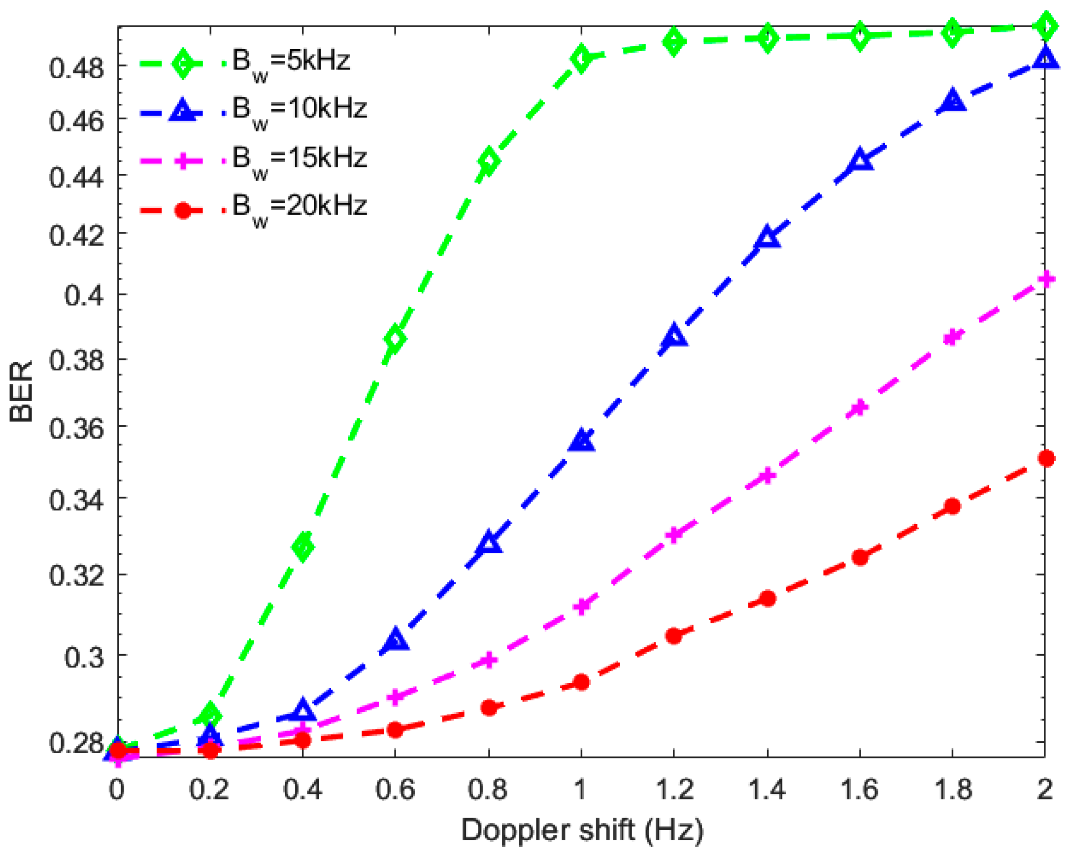
4. Numerical Results and Discussion

In this section, we present the numerical results for the WPCN-based UWAC systems. The derived expressions of average BER and outage probability given in Equations (24) and (31) are used to investigate the system performance under different parameters. Monte-Carlo simulations are provided to verify the analytical results for Equations (24) and (31) as well. Unless otherwise specified, the parameters set in our simulations are shown in Table 2. Note that, for simplicity, the energy harvesting efficiency η is set as a constant in our work.
In Figure 4, the average BER and the outage probability of the WPCN-based UWAC systems under various transmit powers are plotted against the transmission distance. It is shown that the analytical results match very well with the Monte-Carlo simulations. Not surprisingly, it can be observed that the average BER and outage probability increase as the distance increases, since the longer the transmission distance is, the more severe the path loss will be. It can also be observed that as the transmission distance increases, the benefits coming from the increase in the transmit power of H-AP decrease rapidly. Specifically, when the transmit power increases from 150   dB   re   μ Pa to 180   dB   re   μ Pa , an average BER performance improvement of 94.65% is achieved for the system with a transmission distance of 20 m, while the average BER performance improvement is only 12.81% when the transmission distance is 200 m.
To examine the impact of the time allocation factor τ 0 on the performance of the WPCN-based UWAC systems, we plot the achievable rate against the time allocation factor for the systems with various H-AP transmit powers and various transmission distances in Figure 5a,b, respectively. It is shown that despite the variation in H-AP transmit power and transmission distance, there exists an optimal time allocation factor τ 0 (which is marked with a bold circle) for the systems to achieve the maximum information rate. Specifically, for the transmit power of 150   dB   re   μ Pa and 180   dB   re   μ Pa , a maximum information rate of 0.1574 bps/Hz and 2.5333 bps/Hz can be achieved at a transmission distance of 80 m, respectively. Moreover, it can also be observed that the optimal time allocation factor becomes more and more large when the H-AP transmit power decreases or the transmission distance increases. This can be explained as follows. For a smaller H-AP to transmit power, the terminal node needs more time to harvest enough energy for information transmission. While for a larger transmission distance, the downlink energy transmission of the H-AP subjects to a severe path loss, which significantly decreases the power harvested by the terminal node, thus more time is needed for the terminal node to harvest enough energy for information transmission. Therefore, both the smaller H-AP transmit power and the larger transmission distance increase the time required for energy harvesting at the terminal.
Figure 6 shows the average BER versus the signal frequency f for the WPCN-based UWAC systems under various transmission distances d and various spreading factors m . Similar to Figure 5, it can be observed that there exists an optimal value of signal frequency (which is marked with a bold circle) for the systems to obtain the minimum average BER. Specifically, a smaller optimal signal frequency is preferred for a larger transmission distance for the WPCN-based UWAC systems, while the optimal signal frequency remains invariant when the value of the spreading factor changes. The reason is that both the path loss A d , f and noise N f are frequency-dependent, and when the signal frequency increases, the path loss A d , f increases whereas the noise N f decreases, and thus there exists an optimal frequency to obtain the maximum SNR and minimum average BER. According to Equation (3), the spreading factor only acts on the transmission distance and does not affect SNR when the signal frequency changes.
To examine the impact of the Doppler shift f d on the performance of the WPCN-based UWAC systems, we plot the BER against the Doppler shift for the systems with various signal bandwidths in Figure 7. Not surprisingly, it can be observed that the average BER performance is affected by the Doppler shift and that the BER increases as the Doppler shift increases. It can also be observed that as the signal bandwidth increases, the interference coming from the Doppler shift becomes less severe. Specifically, when the Doppler shift increases from 0.2 Hz to 0.6 Hz, the average BER increases by 1.69% for the system with a signal bandwidth of 20 kHz, while the average BER increment is 35.21% when the signal bandwidth is 5 kHz. The reason is that, for a certain number of subcarriers, the subcarrier spacing increases as the bandwidth increases. Thus, the interference between adjacent subcarriers will be less severe.

5. Conclusions

In this paper, we have presented the application of WPCN to the UWAC systems and investigated the performance of the WPCN-based UWAC systems. We have derived tractable and novel closed-form expressions for the PDF of the instantaneous receiving SNR at the H-AP, as well as the average BER and outage probability for the systems. These expressions have been verified by Monte-Carlo simulations. We have also investigated the impacts of various system and channel parameters on the system’s performance. These parameters include transmission distance, spreading factor, signal frequency, time allocation factor, and Doppler shift. The results have demonstrated that the average BER and outage probability are affected by these parameters. It has also been demonstrated that there exist optimal values of signal frequency that minimize the average BER and outage probability, as well as optimal values of time allocation factor that maximize the achievable information rate. In this paper, we assume that all the energy harvested in the downlink is used for information transmission in the uplink. Energy-efficient optimization design for the proposed WPCN-based UWAC systems will be left for future work. Also, we assume a simple binary constellation and perfect CSI for the proposed analysis in our setup, and Monte-Carlo simulation is performed to validate the results. Different modulation, coding, channel estimation, equalization schemes, and field experiments for the proposed analysis can be further investigated. New subjects can be investigated to expand the work in this paper to the scenario of numerous users.

Author Contributions

Conceptualization and methodology, Y.F., R.X. and Y.Z.; software and validation, R.X. and Y.Z.; formal analysis and data curation, R.X. and Y.Z.; writing—original draft preparation, Y.F. and R.X.; supervision, Y.F. and F.J. All authors have read and agreed to the published version of the manuscript.

Funding

This research was funded by the National Natural Science Foundation of China, grant numbers 62171187 and 62192712, and the Guangdong Basic and Applied Basic Research Foundation, grant number 2022A1515011476.

Institutional Review Board Statement

Not applicable.

Informed Consent Statement

Not applicable.

Data Availability Statement

The data presented in this paper are available upon request from the corresponding author.

Acknowledgments

The authors would like to thank the anonymous reviewers for their careful reading and valuable comments.

Conflicts of Interest

The authors declare no conflicts of interest.

References

  1. Rahmati, M.; Pompili, D. UNISeC: Inspection, separation, and classification of underwater acoustic noise point sources. IEEE J. Ocean. Eng. 2017, 43, 777–791. [Google Scholar] [CrossRef]
  2. Han, M.; Duan, J.; Khairy, S.; Cai, L.X. Enabling sustainable underwater IoT networks with energy harvesting: A decentralized reinforcement learning approach. IEEE Internet Things J. 2020, 7, 9953–9964. [Google Scholar] [CrossRef]
  3. Ju, H.; Zhang, R. Throughput maximization in wireless powered communication networks. IEEE Trans. Wirel. Commun. 2013, 13, 418–428. [Google Scholar] [CrossRef]
  4. Bi, S.; Zeng, Y.; Zhang, R. Wireless powered communication networks: An overview. IEEE Wirel. Commun. 2016, 23, 10–18. [Google Scholar] [CrossRef]
  5. Chen, X.; Zhang, Z.; Chen, H.-H.; Zhang, H. Enhancing wireless information and power transfer by exploiting multi-antenna techniques. IEEE Commun. Mag. 2015, 53, 133–141. [Google Scholar] [CrossRef]
  6. Yi, F.; Fei, J. Wireless Information and Power Transfer in Underwater Acoustic Sensor Networks. China Commun. 2020; accepted. [Google Scholar]
  7. Liu, F.; Phipps, A.; Horowitz, S.; Ngo, K.; Cattafesta, L.; Nishida, T.; Sheplak, M. Acoustic energy harvesting using an electromechanical Helmholtz resonator. J. Acoust. Soc. Am. 2008, 123, 1983–1990. [Google Scholar] [CrossRef] [PubMed]
  8. Radosevic, A.; Ahmed, R.; Duman, T.M.; Proakis, J.G.; Stojanovic, M. Adaptive OFDM modulation for underwater acoustic communications: Design considerations and experimental results. IEEE J. Ocean. Eng. 2013, 39, 357–370. [Google Scholar] [CrossRef]
  9. Stojanovic, M. OFDM for underwater acoustic communications: Adaptive synchronization and sparse channel estimation. In Proceedings of the 2008 IEEE International Conference on Acoustics, Speech and Signal Processing, Las Vegas, NV, USA, 31 March–4 April 2008; pp. 5288–5291. [Google Scholar]
  10. Cao, R.; Yang, L.; Qu, F. On the capacity and system design of relay-aided underwater acoustic communications. In Proceedings of the 2010 IEEE Wireless Communication and Networking Conference, Sydney, NSW, Australia, 18–21 April 2010; pp. 1–6. [Google Scholar]
  11. Al-Dharrab, S.; Muqaibel, A.; Uysal, M. Performance of multicarrier cooperative communication systems over underwater acoustic channels. IET Commun. 2017, 11, 1941–1951. [Google Scholar] [CrossRef]
  12. Bouvet, P.-J.; Auffret, Y. On the achievable rate of multiple-input–multiple-output underwater acoustic communications. IEEE J. Ocean. Eng. 2019, 45, 1126–1137. [Google Scholar] [CrossRef]
  13. Chen, K.; Ma, M.; Cheng, E.; Yuan, F.; Su, W. A survey on MAC protocols for underwater wireless sensor networks. IEEE Commun. Surv. Tutor. 2014, 16, 1433–1447. [Google Scholar] [CrossRef]
  14. Jiang, S. State-of-the-art medium access control (MAC) protocols for underwater acoustic networks: A survey based on a MAC reference model. IEEE Commun. Surv. Tutor. 2017, 20, 96–131. [Google Scholar] [CrossRef]
  15. Rajasoundaran, S.; Kumar, S.S.; Selvi, M.; Thangaramya, K.; Arputharaj, K. Secure and optimized intrusion detection scheme using LSTM-MAC principles for underwater wireless sensor networks. Wirel. Netw. 2023, 1–23. [Google Scholar] [CrossRef]
  16. Guo, J.; Song, S.; Liu, J.; Chen, H.; Cui, J.-H.; Han, G. A Hybrid NOMA-Based MAC Protocol for Underwater Acoustic Networks. IEEE/ACM Trans. Netw. 2023, 1–14. [Google Scholar] [CrossRef]
  17. Rice, J.; Creber, B.; Fletcher, C.; Baxley, P.; Rogers, K.; McDonald, K.; Rees, D.; Wolf, M.; Merriam, S.; Mehio, R. Evolution of seaweb underwater acoustic networking. In Proceedings of the OCEANS 2000 MTS/IEEE Conference and Exhibition, Conference Proceedings (Cat. No. 00CH37158). Providence, RI, USA, 11–14 September 2000; pp. 2007–2017. [Google Scholar]
  18. Melodia, T.; Kulhandjian, H.; Kuo, L.C.; Demirors, E. Advances in underwater acoustic networking. In Mobile Ad Hoc Networking: Cutting Edge Directions; Wiley: Hoboken, NJ, USA, 2013; pp. 804–852. [Google Scholar]
  19. Dol, H.; Blom, K.; Sotnik, D.; Nissen, I.; Otnes, R.; Komulainen, A.; Campagnaro, F. EDA-SALSA: Development of a self-reconfigurable protocol stack for robust underwater acoustic networking. In Proceedings of the OCEANS 2023-Limerick, Limerick, Ireland, 5–8 June 2023; pp. 1–10. [Google Scholar]
  20. Lu, W.; Cui, H.; Ling, D. Design and research of underwater acoustic communication system. In Proceedings of the International Conference on Signal Processing and Communication Technology (SPCT 2022), Harbin, China, 23–25 December 2022; pp. 418–423. [Google Scholar]
  21. Chaffey, M.; Bird, L.; Erickson, J.; Graybeal, J.; Hamilton, A.; Headley, K.; Kelley, M.; McBride, L.; Mellinger, E.; Meese, T. MBARI’s buoy based seafloor observatory design. In Proceedings of the Oceans’ 04 MTS/IEEE Techno-Ocean’04 (IEEE Cat. No. 04CH37600), Kobe, Japan, 9–12 November 2004; pp. 1975–1984. [Google Scholar]
  22. Wang, R.; Makled, E.A.; Yadav, A.; Dobre, O.A.; Zhao, R. Reinforcement learning-based energy-efficient power allocation for underwater full-duplex relay network with energy harvesting. In Proceedings of the 2020 IEEE 92nd Vehicular Technology Conference (VTC2020-Fall), Victoria, BC, Canada, 18 November–16 December 2020; pp. 1–5. [Google Scholar]
  23. Zhang, B.; Xu, W.; Lu, C.; Lu, Y.; Wang, X. Review of low-loss wireless power transfer methods for autonomous underwater vehicles. IET Power Electron. 2022, 15, 775–788. [Google Scholar] [CrossRef]
  24. Chen, F.; Zhang, J.; Cui, S.; Bie, Z.; Zhu, C. A Novel Pendulum-Type Magnetic Coupler with High Misalignment Tolerance for AUV Underwater Wireless Power Transfer Systems. IEEE Trans. Power Electron. 2023, 38, 14861–14871. [Google Scholar]
  25. Kesari Mary, D.R.; Ko, E.; Yoon, D.J.; Shin, S.-Y.; Park, S.-H. Energy Optimization Techniques in Underwater Internet of Things: Issues, State-of-the-Art, and Future Directions. Water 2022, 14, 3240. [Google Scholar] [CrossRef]
  26. Huang, C.-J.; Wang, Y.-W.; Liao, H.-H.; Lin, C.-F.; Hu, K.-W.; Chang, T.-Y. A power-efficient routing protocol for underwater wireless sensor networks. Appl. Soft Comput. 2011, 11, 2348–2355. [Google Scholar] [CrossRef]
  27. Nguyen, T.H.; Shin, S.-Y.; Park, S.-H. Efficiency reservation MAC protocol for underwater acoustic sensor networks. In Proceedings of the 2008 Fourth International Conference on Networked Computing and Advanced Information Management, Gyeongju, Republic of Korea, 2–4 September 2008; pp. 365–370. [Google Scholar]
  28. Guida, R.; Demirors, E.; Dave, N.; Melodia, T. Underwater ultrasonic wireless power transfer: A battery-less platform for the internet of underwater things. IEEE Trans. Mob. Comput. 2022, 21, 1861–1873. [Google Scholar] [CrossRef]
  29. Liu, Z.; Zhang, T.; Geng, Y.; An, T. Underwater Wireless High-Efficiency Energy Transmission Method Based on the Ultrasonic Transducer Array. In Proceedings of the 2021 IEEE 21st International Conference on Communication Technology (ICCT), Tianjin, China, 13–16 October 2021; pp. 192–197. [Google Scholar]
  30. Varshney, L.R. Transporting information and energy simultaneously. In Proceedings of the 2008 IEEE International Symposium on Information Theory, Toronto, ON, Canada, 6–11 July 2008; pp. 1612–1616. [Google Scholar]
  31. Zhou, X.; Zhang, R.; Ho, C.K. Wireless information and power transfer: Architecture design and rate-energy tradeoff. IEEE Trans. Commun. 2013, 61, 4754–4767. [Google Scholar] [CrossRef]
  32. Ju, H.; Zhang, R. User cooperation in wireless powered communication networks. In Proceedings of the 2014 IEEE Global Communications Conference, Austin, TX, USA, 8–12 December 2014; pp. 1430–1435. [Google Scholar]
  33. Zhong, C.; Chen, X.; Zhang, Z.; Karagiannidis, G.K. Wireless-powered communications: Performance analysis and optimization. IEEE Trans. Commun. 2015, 63, 5178–5190. [Google Scholar] [CrossRef]
  34. Ji, T.; Hua, M.; Li, C.; Huang, Y.; Yang, L. Exploiting Intelligent Reflecting Surface for Enhancing Full-Duplex Wireless-Powered Communication Networks. IEEE Trans. Commun. 2023, 1. [Google Scholar] [CrossRef]
  35. Hu, G.; Cai, Y. Energy-accumulation-based power-beacon-assisted WPCN: Time allocation and scheduling schemes. IEEE Commun. Lett. 2019, 23, 1510–1514. [Google Scholar] [CrossRef]
  36. Doosti-Aref, A.; Ebrahimzadeh, A. Adaptive relay selection and power allocation for OFDM cooperative underwater acoustic systems. IEEE Trans. Mob. Comput. 2017, 17, 1–15. [Google Scholar] [CrossRef]
  37. Domínguez-Bolaño, T.; Rodríguez-Piñeiro, J.; García-Naya, J.A.; Castedo, L. Bit error probability and capacity bound of OFDM systems in deterministic doubly-selective channels. IEEE Trans. Veh. Technol. 2020, 69, 11458–11469. [Google Scholar] [CrossRef]
  38. Qarabaqi, P.; Stojanovic, M. Statistical characterization and computationally efficient modeling of a class of underwater acoustic communication channels. IEEE J. Ocean. Eng. 2013, 38, 701–717. [Google Scholar] [CrossRef]
  39. Stojanovic, M. On the relationship between capacity and distance in an underwater acoustic communication channel. ACM SIGMOBILE Mob. Comput. Commun. Rev. 2007, 11, 34–43. [Google Scholar] [CrossRef]
  40. Coates, R.F.; Coates, R. Underwater Acoustic Systems; Springer: Berlin/Heidelberg, Germany, 1990. [Google Scholar]
  41. Feng, Y.; Wen, M.; Ji, F.; Leung, V.C. Performance analysis for BDPSK modulated SWIPT cooperative systems with nonlinear energy harvesting model. IEEE Access 2018, 6, 42373–42383. [Google Scholar] [CrossRef]
  42. Papoulis, A.; Unnikrishna Pillai, S. Probability, Random Variables and Stochastic Processes; McGraw-Hill Europe: New York, NY, USA, 2002. [Google Scholar]
  43. Shankar, P.M. Fading and Shadowing in Wireless Systems; Springer: New York, NY, USA, 2012. [Google Scholar]
  44. Simon, M.K.; Alouini, M. A unified approach to the performance analysis of digital communication over generalized fading channels. Proc. IEEE 1998, 86, 1860–1877. [Google Scholar] [CrossRef]
  45. Sileh, I.K.; Xiang, W.; Alajel, K.M. Outage probability of unequal block-based OFDM amplify-and-forward relay protocol over wideband channels. In Proceedings of the 2012 International Symposium on Communications and Information Technologies (ISCIT), Gold Coast, QLD, Australia, 2–5 October 2012; pp. 599–603. [Google Scholar]
Figure 1. The architecture of UWAC systems.
Jmse 12 00043 g001
Figure 2. Module components for a WPCN-based underwater acoustic terminal node.
Jmse 12 00043 g002
Figure 3. The harvest-then-transmit protocol.
Jmse 12 00043 g003
Figure 4. The average BER and outage probability performance versus transmission distance for various transmit powers: (a) the average BER performance; and (b) the outage probability performance.
Jmse 12 00043 g004
Figure 5. Achievable rates versus time allocation factors: (a) impact of various transmit powers (d = 80 m); and (b) impact of various transmission distances ( P d = 170 dB   re   μ Pa ).
Jmse 12 00043 g005
Figure 6. The average BER versus signal frequency (Pd = 200 dB   re   μ Pa ): (a) impact of various transmission distances; and (b) impact of various spreading factors ( d = 300   m ).
Jmse 12 00043 g006
Figure 7. The average BER versus Doppler shift for various signal bandwidths (Pd = 170 dB   re   μ Pa and d = 60   m ).
Jmse 12 00043 g007
Table 1. Harvested energy under various transmit power and transmission distances. (transducer directivity D I = 10 dB , signal center frequency f = 15 kHz , and spreading factor m = 1.5 ).
Transmit
Power (W)
Transmission
Distance (m)
Received   SPL   ( dB   re   μ Pa )Harvested
Power (mW)
20100163.136.3
30100164.838.2
40100166.139.8
20200158.830.2
30200160.632.9
40200161.834.4
20300155.927.9
30300157.729.0
40300158.930.3
Table 2. Parameters setup in the simulations.
ParametersSymbolValue
Spreading factor m 1.5
Shipping activity factor s 0.5
Wind speed w 3 m/s
Downlink OFDM subcarrier number K 32
Uplink OFDM subcarrier number I 32
Number of multipaths L p 5
Multipath delay τ 0, 0.3, 0.5, 0.6, 0.8 ms
Outage rate threshold R t h 10 3 bps/Hz
Energy conversion efficiency η 0.8
Signal center frequency f 10 kHz
Signal bandwidth B w 10 kHz
Time allocation factor τ 0 0.8
Speed of sound in the water c 0 1500 m/s
Doppler shift f d 0 Hz
Disclaimer/Publisher’s Note: The statements, opinions and data contained in all publications are solely those of the individual author(s) and contributor(s) and not of MDPI and/or the editor(s). MDPI and/or the editor(s) disclaim responsibility for any injury to people or property resulting from any ideas, methods, instructions or products referred to in the content.

