1. Introduction
In recent years, the application of floating-type substructures has been accelerating due to an increase in offshore wind turbine system capacity, while the destructive power of typhoons is increasing every year due to global warming, and the risk of damage to offshore structures is increasing. Measures are needed to prevent serious damage to floating-type offshore wind turbines and prevent rapid system collapse due to extreme offshore environmental loads, such as typhoons. In this regard, there is a need to develop a new type of disconnectable mooring system that not only enables evacuation but also reduces the cost of offshore installation and maintenance work. Fairlead chain stoppers (FCS) and submersible mooring pulleys (SMP) are mooring apparatuses for disconnectable mooring systems designed to facilitate the installation and decommissioning of floating-type substructures more safely than conventional disconnectable mooring apparatuses. They are also meant to enable the installation and decommissioning of floating-type offshore wind turbines in a short time.
Newly designed disconnectable mooring apparatuses for floating-type offshore wind turbines, such as FCS and SMP, require a thorough structural safety review from the initial design stage to ensure that they can be used safely in a severe marine environment. In the early conceptual design stage, the structural safety of offshore wind turbine apparatuses, such as FCS and SMP, can generally be reviewed through numerical analyses, but numerical analyses have uncertainties in modelling, loading and boundary conditions, the application of material constitutive equation theory, etc. This study aims to propose a methodology in which the numerical analysis results are verified by structural model tests using a 3-D printer.
Some studies have been conducted to evaluate the structural safety of apparatuses installed on offshore wind turbine systems or offshore structures. Lee et al. [
1] performed structural analysis using the finite element method to examine the structural safety of the initial design of a passive-type deck support frame designed for the float-over installation of an offshore plant and explored the optimal design method that can be applied to the structural design most efficiently. Song et al. [
2] evaluated the structural design safety of a marine loading arm used for the loading and unloading operations of crude oil carriers based on the finite element analysis by applying the international design load conditions. Lee et al. [
3] developed a tensile force application NL-tensioner to prevent damage to risers installed on drill ships or drilling rigs for floating production, storage, and offloading (FPSO) units. Song et al. [
4] performed a structural analysis of a riser support structure for an FPSO considering global and local loading conditions and identified the optimal shape design using a topology optimization technique. Song et al. [
5] calculated dynamic loading conditions through the hydrodynamic analysis of floating offshore solar panels in a mooring state and used them to perform a structural analysis of the solar panel support structures. Song and Kim [
6] identified the fire resistance characteristics of an enhanced bulkhead penetration piece designed for an A-0 class compartment using coupled heat transfer and thermal structure analyses and carried out an actual fire resistance test in accord with the test procedure prescribed for international marine regulation. Park and Song [
7] carried out approximate optimization with discrete variables for the fire resistance design of an A60 class bulkhead penetration piece installed on ships and offshore structures using various meta-models and multi-island genetic algorithms. Kim and Song [
8] carried out a comparative study assessing the characteristics of the approximation of a design space of an active-type deck support frame that was developed for the float-over installation of offshore plants according to various approximate models and a sensitivity analysis using orthogonal array experiments. Yue et al. [
9] proposed a systematic multi-objective optimization framework for preventive maintenance interval optimization and established two dynamic risk models for the evaluation of dynamic risk profiles of safety-critical equipment in the operational phase and preventive maintenance phase, respectively. Shahzamanian [
10] carried out an implementation and analysis of the anisotropic version of the Gurson–Tvergaard–Needleman isotropic damage criterion using Hill’s quadratic anisotropic yield theory with the definition of an effective anisotropic coefficient to represent the elastic-plastic behavior of ductile metals. Abdulhakim et al. [
11] carried out a sensitivity analysis of these inherent stochastic variables imposed on a complex offshore wind turbine support structure via a purpose-developed modular non-intrusive structural reliability assessment formulation. Song [
12] evaluated the penetration characteristics of anchor piles into the soil under which subsea high-voltage direct current cables were embedded using numerical simulations and field verification tests.
In this study, to ascertain the structural safety of disconnectable mooring apparatuses such as FCS and SMP, which are designed to be applied to the mooring system of megawatt-class floating-type offshore wind turbines, scaled-down structural models were produced using a 3-D printer, and structural tests and structural analyses were performed to evaluate their strength performance. Before conducting the scaled-down structural model tests on the actual shapes of FCS and SMP, tensile specimens of acrylonitrile butadiene styrene (ABS), the material of the 3-D printer’s printouts, were fabricated, and material properties were calculated through tensile tests. In order to numerically evaluate the structural weaknesses of FCS and SMP and verify the structural weaknesses through the structural tests, finite element analysis models were generated in the same form as the scaled-down structural model. The material properties calculated from the tensile test were applied to finite element analysis models. The loading and boundary conditions applied in the finite element analyses were the same as those in the scaled-down model’s structural test. The scaled-down model’s structural test was performed by implementing the loading state considering the actual operating state of FCS and SMP, and the structural test results were compared with the structural analysis results to examine the validity of the test conditions and results. This study provides a method of testing the structural safety of disconnectable mooring apparatus for floating-type offshore wind turbines at the early design stage, and the strength performance evaluation results of FCS and SMP can be used to improve the structural performance at the detailed design stage. This paper is comprised of the following sections.
Section 2 addresses the design characteristics of FCS and SMP for floating-type offshore wind turbines.
Section 3 addresses the tensile tests of the ABS material and describes the strength evaluation results from the finite element analyses.
Section 4 addresses the strength evaluation results via the scaled-down structural model tests and discusses the comparison of results from the numerical analysis and test.
Section 5 presents the concluding remarks of this study.
2. Design Characteristics of FCS and SMP
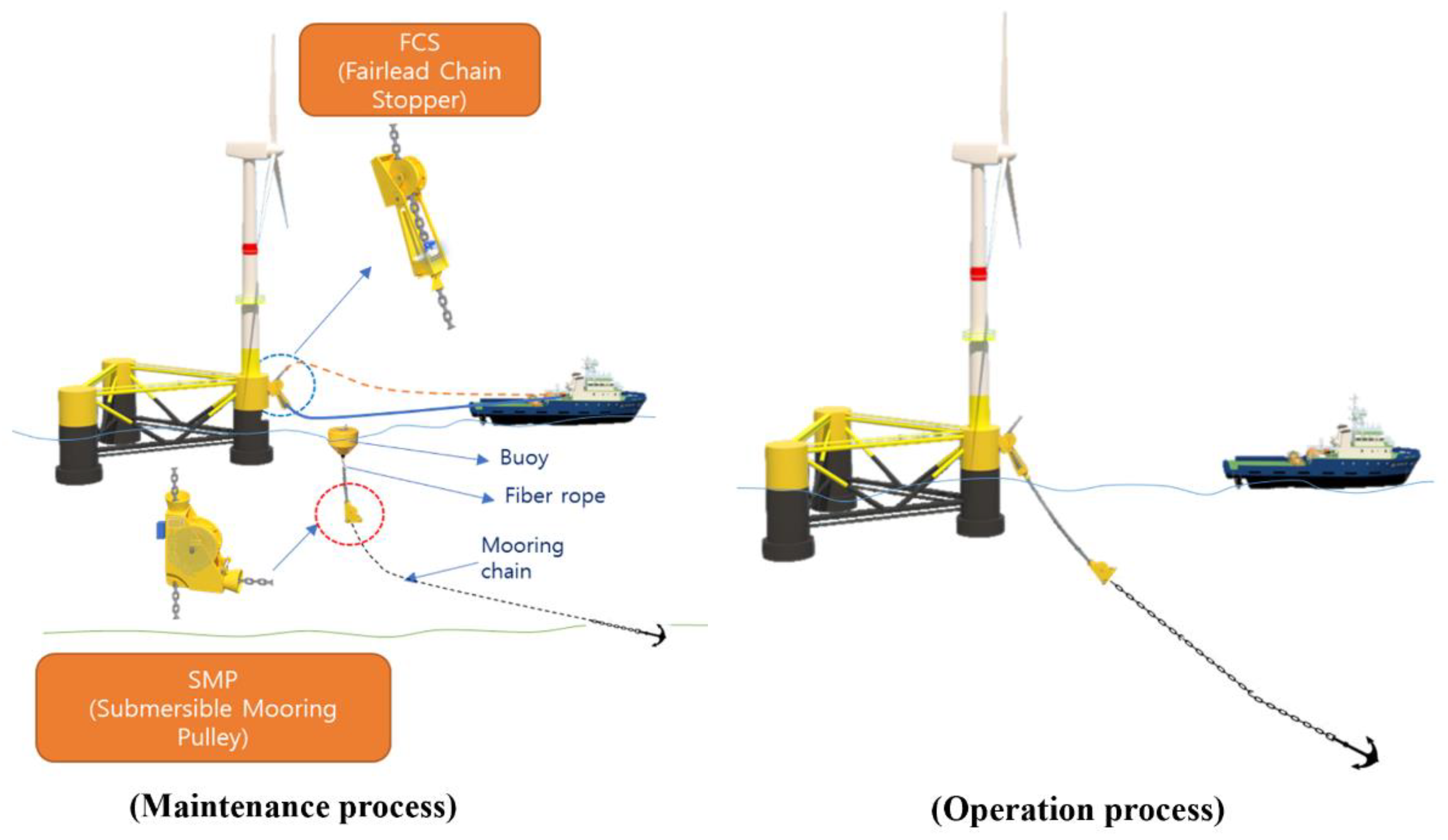
The mooring system, which is a positioning system that directly affects the global behaviour of the substructure in floating-type offshore wind turbines, is an essential core component for securing the motion stability and positioning of the entire wind turbine system and stable power generation performance. Recently, typhoons that exceed the design limit flow rate of floating-type offshore wind turbines have occurred, and larger typhoons are expected in the future due to climate change, so it is absolutely necessary to consider the disconnectable apparatuses of the mooring system for the evacuation of the floating-type offshore wind turbines or large-scale maintenance due to severe damage. The operational characteristics of FCS and SMP, the disconnectable mooring apparatuses of floating-type offshore wind turbines considered in this study, are shown in
Figure 1. As shown in
Figure 1, the FCS is designed to be installed on the side of the substructure in the mooring system designed to separate the upper and lower parts from the water surface. The FCS is connected to the tug line of the offshore support vessel during the installation and maintenance processes of the floating-type offshore wind turbine to prevent direct damage to the substructure. The FCS is also designed to be connected to the mooring chain after the installation is completed to minimize damage to the substructure due to the load of the mooring system generated during the operation of the floating-type offshore wind turbine. The SMP is designed to be installed between the buoy and the mooring chain during the installation process and connected to the FCS of the substructure during the decommissioning process. Since damage to the mooring system of floating-type offshore wind turbines usually occurs at the substructure connection, the application of a disconnectable-type mooring system eliminates the need to replace the entire mooring system during the maintenance process. Therefore, the effect of shortening the maintenance period and reducing costs due to the adoption of FCS and SMP is higher than that of a conventional mooring system.
The initial design configuration and main dimensions of the FCS and SMP considered in this study are shown in
Figure 2.
As shown in
Figure 2, the FCS and SMP are designed to connect to the mooring chain at sea level and ensure structural safety under the maximum tensile force of 2250 tonnes. The FCS consists of six main components: the fairlead wheel, fairlead arm, chain stopper, flag block, connector, and hydraulic system. The fairlead wheel is the component that guides the movement of the mooring chain during installation or decommissioning. The fairlead arm is the component that guides the movement of the mooring chain and transfers the support load of the chain stopper to the FCS structural components. The chain stopper is a component that supports the chain load during operation, installation, or decommissioning. The flag block is a component for connecting the FCS to the substructure. The connector and hydraulic system control the operation of the chain stopper. The main parts of the FCS are connected by pins to allow rotational motion. The SMP consists of five main parts: the wheel, body, chain stopper, shackle, and connector. The wheel is the part that guides the movement of the mooring chain during installation or decommissioning. The body is the structural part that holds the components of the SMP together. The chain stopper is a component that supports the chain load during operation, installation, or decommissioning. The shackle is a component for connecting the mooring chain to the SMP. The connector is the component that controls the operation of the chain stopper. The main parts of the SMP are connected by pins to allow rotational motion.
3. Finite-Element-Analysis-Based Strength Performance Evaluation
Before performing scaled-down structural model tests on the actual geometry of FCS and SMP, it was necessary to evaluate the strength performance based on finite element analysis under the same conditions as the scaled-down structural model in order to numerically examine the structural weaknesses and verify the structural weaknesses through structural tests. To improve the accuracy of the finite element analysis results, the material’s properties were obtained by fabricating material specimens and performing tensile tests using the same 3-D printer used to produce the scaled-down structural model. In addition, the loading and boundary conditions of the finite element analysis were set the same as those of the structural model tests, and the stress results were calculated to evaluate the areas of structural weakness in the model test.
In this study, since the scaled-down structural models of FCS and SMP were produced by 3-D printing, the material properties of the finite element analysis were obtained from the tensile test of ABS, which is the material of the 3-D printer printout. Since the mechanical properties of the ABS material can be affected by the working conditions of the 3-D printer, the same 3-D printer used to produce the scaled-down structural model was used to produce tensile test specimens of the ABS material, and the material properties were calculated. Since the ABS material has orthotropic properties that are affected by the orientation of the laminated layer, it was necessary to fabricate specimens and perform tensile tests according to the lamination direction [
13,
14,
15]. Considering the geometry of three-dimensional structures such as FCS and SMP, tensile specimens of orthotropic materials should be fabricated in the length, width, and height directions of the specimen. Therefore, tensile test specimens of ABS materials were fabricated by printing out the length, width, and height directions, as shown in
Figure 3.
The 3-D printer used to produce the tensile test specimens was a fused filament fabrication output type, and the diameters of the nozzle and filament were 0.4 mm and 1.75 mm. The nozzle temperature and bed temperature of the 3-D printer were set to 250 °C and 115 °C, respectively, to produce the tensile test specimens. The tensile test specimen was manufactured according to the ASTM D638 standard test method [
16], and the design and manufacturing geometry of the tensile test specimen is shown in
Figure 4.
The tensile tests were performed on ABS specimens fabricated in the length, width, and height directions, respectively. The instrumentation used for the tensile test was a 250 kN class universal test machine (UTM) manufactured by MTS, and the test conditions are shown in
Figure 5.
As shown in
Figure 5, the elongation of the specimen was measured using a contact extensometer, and the strain rate of the tensile test was set to 5 mm/min. The main results of the tensile test, such as the ultimate tensile stress, the elongation, and the modulus of elasticity, are summarized in
Table 1, and the stress–strain curve is shown in
Figure 6.
As shown in
Table 1 and
Figure 6, the tensile strength of the height-wise lamination (TS
H) condition is about 5% and 9% higher than the length-wise lamination (TS
L) and width-wise lamination (TS
W) conditions. These characteristics are consistent with previous studies [
10,
12], so the results of the tensile test are considered valid. From the tensile test results, it can be seen that the mechanical properties of ABS are anisotropic. Therefore, in order to apply the ABS material properties obtained from the tensile tests to the finite element analysis, the orthotropic material constants must be estimated. The orthotropic material model for determining the orthotropic material constants can be defined as follows [
17].
where
is the tensile stress,
is the tensile strain,
is the elastic modulus,
is Poisson’s ratio of
i axial strain to
j axial strain, and
is the shear modulus for the
i axis and the plane orthogonal to the
j axis. The orthotropic material constants of Poisson’s ratio and the shear modulus calculated from
Table 1 and Equation (2) are summarized in
Table 2.
In order to numerically investigate the structural weaknesses of the FCS and SMP and to verify the structural weaknesses through the structural testing of the scaled-down model, finite element analysis models were generated in the same configuration as the scaled-down structural model. The scale of the scaled-down structural models was set to 1/12 to allow for mounting on the UTM. The scaled-down structural models were generated using modified CAD models that maintained the same geometry as the actual-size FCS and SMP structures in three dimensions while scaling the CAD data down to 1/12. The finite element analysis models of FCS and SMP are shown in
Figure 7.
As shown in
Figure 7, the FCS finite element model consisted of 941,268 elements and 214,505 nodes, while the SMP finite element model consisted of 1,320,711 elements and 312,027 nodes. Each component was modelled with a four-node tetrahedral element, and the connections between the components were modelled with rigid links. The material properties applied to the finite element models were orthotropic material properties obtained from tensile tests. The loading conditions applied to the finite element analyses were the operation condition, where the mooring chain is connected to the wheel and subjected to tensile load, and the anchoring condition, where the chain is anchored to the chain stopper, considering the actual working situations of the FCS and SMP, respectively. Since the scaled-down model structural test implements the tensile load condition through displacement control, the same forced displacement was applied as the loading condition in the finite element analysis models. A displacement control curve was used to apply a linear increment of 5.0 mm in the tensile direction on the wheel and chain stopper. The boundary conditions of the FCS were set as the fully fixed constraints at the corresponding nodal points in the finite element analysis model because the upper surface of the flag block and the lower surface of the fairlead arm were required to be fixed in the scaled-down model’s structural test. Since the boundary condition of SMP requires fixing the top surface and bottom surface of the body in the scaled-down model’s structural test, the degrees of freedom of the corresponding nodes were set as the fully fixed constraints in the finite element analysis model. The finite element analyses of FCS and SMP were performed using ABAQUS/Implicit [
18], a general-purpose finite element analysis software. In order to investigate the areas of damage in the FCS and SMP due to the plastic material’s behaviour through the finite element analysis, the option for the plastic material yield stress available in ABAQUS was used in this study. Brittle materials, such as ABS, typically fail suddenly when subjected to stress levels that exceed the material strength, and its damage or failure is often associated with the development and propagation of cracks or voids. The damage mode analysis in the finite element method was applied to simulate the damage evolution and failure of brittle materials by reducing the material’s stiffness and strength as damage accumulates. The material was assumed to have an initial level of damage, and as the stress in the material increased, the damage accumulated and caused a reduction in the material’s stiffness and strength. When the damage accumulated to a critical level, the material was assumed to have failed. The critical level was obtained from the material damage test. Since this study used only the tensile test results of the ABS material to perform the finite element analysis, the damaged areas were estimated based on the hot spots where the yield stresses were concentrated. The finite element analysis results of the operation condition and anchoring condition are shown in
Figure 8 using von Mises stresses.
As shown in
Figure 8, under the maximum forced displacement applied by the load, both the operation condition and the anchoring condition reached the maximum tensile stress of the material, which is 13.89 MPa. In this way, as the load is applied to the maximum tensile stress of the material, the structural vulnerability of each load condition can be clearly determined. In the case of FCS, the connection between the flag block and the fairlead wheel was found to be weak in the operation condition, while the connection between the fairlead arm and the chain stopper was found to be weak in the anchoring condition. In the case of SMP, the connection structure of the body and the wheel was found to be weak in the operation condition, while the connection structure of the body and the chain stopper was found to be weak in the anchoring condition.
4. Strength Performance Evaluation Based on Scaled-down Model Test
To verify the structural weaknesses of the FCS and SMP identified through the finite element analyses, structural tests of the scaled-down models were performed. The scaled-down models were fabricated using the same 3-D printer used to fabricate the tensile test specimen made of ABS. The nozzle temperature and bed temperature of the 3-D printer were also set to the same conditions as the tensile test specimen. The geometries of the scale-down models of FCS and SMP produced by 3-D printing are shown in
Figure 9.
To mount the scale-down model of the FCS, shown in
Figure 9a, to the UTM, separate jigs were installed on the top surface of the flag block and the bottom surface of the fairlead arm. To mount the scaled-down model of the SMP, shown in
Figure 9b, to the UTM, separate jigs were installed on the top surface and bottom surface of the body. The structural test status of the scaled-down model of the FCS is shown in
Figure 10 by the operation condition and the anchoring condition.
As shown in
Figure 10, the load conditions for the operation condition and anchoring condition were implemented by connecting wires to the fairlead wheel and chain stopper and fixing them to the load cell to simulate the actual working situation of FCS. The structural test status of the scaled-down model of the SMP is shown in
Figure 11 by the operation condition and the anchoring condition.
As shown in
Figure 11, the load conditions for the operation condition and anchoring condition were implemented by connecting wires to the wheel and chain stopper and fixing them to the load cell to simulate the actual working situation of SMP. The test equipment was the 250 kN class UTM from MTS; the strain rate was set to 5 mm/min in the upward direction, and the test was carried out until structural failure occurred. After the end of the test, the configurations of the fracture zone and the load–displacement history curves of the scaled-down FCS and SMP models are shown in
Figure 12,
Figure 13,
Figure 14 and
Figure 15, respectively.
As shown in
Figure 12, cracks occurred in the connecting areas between the flag block and the fairlead wheel, and the connection pin was found to be broken in the operation condition of the FCS. The connecting area and the connection pin of the fairlead arm and the chain stopper were found to be broken in the anchoring condition. The structural weaknesses of the FCS in the scaled-down model’s structural test were consistent with the results of the finite element analyses. As shown in
Figure 13, the maximum load and maximum displacement of the FCS in the operation condition were 1.76 kN and 15.40 mm, and the maximum load and maximum displacement in the anchoring condition were 1.15 kN and 33.45 mm. The maximum load in the anchoring condition was reduced by 35% compared to the operation condition, while the maximum displacement was increased by 117%. As shown in
Figure 14, in the operating condition of the SMP, a fracture occurred in the connection structure between the body and the wheel, and a crack occurred in the constraint area at the top of the body. In the anchoring condition, cracks occurred in the connecting areas between the body and the chain stopper. The structural weaknesses of the SMP in the scaled-down model’s structural test were consistent with the results of the finite element analyses. As shown in
Figure 15, the maximum load and maximum displacement of the SMP in the operation condition were measured to be 4.87 kN and 30.14 mm, and the maximum load and maximum displacement in the anchoring condition were measured to be 3.84 kN and 72.52 mm. The maximum load in the anchoring condition was reduced by 21% compared to the operation condition, while the maximum displacement was increased by 141%. As shown in the load–displacement history curves in
Figure 13 and
Figure 15, the anchoring condition is more favourable than the operation condition in terms of the absorption of strain energy. It can be concluded that the strain energy characteristics are different because the load application location from the top surface of the fixed boundary part is longer in the anchoring condition, and the configuration of the connecting components along the load transfer path is different. The results of the strength characteristics of FCS and SMP are important structural performance evaluation information that can be used in connection with structural design improvement or optimization. Since the structural test of the scaled-down model was conducted by implementing the loading state considering the actual working situation of FCS and SMP, the test method and results can be used to improve the structural performance of FCS and SMP in the detailed design stage and can also be applied to the full-scale field tests of FCS and SMP. In the detailed design phase, the actual FCS and SMP will be designed with steel material for offshore structures. In the early conceptual design stage, structural safety can generally be reviewed through numerical analyses, but numerical analyses have uncertainties in modelling, loading and boundary conditions, and the application of material constitutive equation theory. Therefore, if the results of the numerical analysis are verified by structural tests, more useful design improvements can be determined in the detailed design phase.
5. Conclusions
In this paper, the strength performances of FCS and SMP developed to be applied to the mooring system of megawatt-class floating-type offshore wind turbines were evaluated by carrying out structural tests and the finite element analyses on scaled-down models fabricated by a 3-D printer to investigate the structural safety at the initial design stage. Before performing structural tests on the scaled-down model for the initial design configuration of FCS and SMP, tensile specimens of ABS material, which is the material of the 3-D printer’s printout, were fabricated, and the material properties were obtained through tensile tests. Since ABS material has orthotropic properties that are affected by the directional characteristics of the lamination layer, test specimens were made in the length, width, and height directions according to the lamination direction, and the tensile tests of ABS material were performed according to the ASTM D638 standard test method to measure the mechanical properties of the material.
In order to numerically find out the structural weaknesses of FCS and SMP and verify the structural weaknesses through the structural tests, finite element analysis models were generated in the same configuration as the scaled-down structural model, and the orthotropic material properties obtained from the tensile tests were applied to the analysed models. The loading conditions applied to the finite element analyses were based on the actual working situations of the FCS and SMP, including the operation condition, where the mooring chain is connected to the wheel and subjected to tensile loads, and the anchoring condition, where the mooring chain is anchored to the chain stopper. The load was applied to the maximum tensile stress of the material to clearly determine the structural vulnerability for each load condition. Based on the finite element analysis results of the FCS, the connection between the flag block and the fairlead wheel was identified as vulnerable in the operation condition, while the connection between the fairlead arm and the chain stopper was confirmed as vulnerable in the anchoring condition. Based on the finite element analysis results of SMP, the connection structure of the body and wheel was found to be weak in the operation condition, and the connection structure of the body and chain stopper was found to be weak in the anchoring condition.
To verify the structural weaknesses of the FCS and SMP identified through the finite element analyses, the structural tests of the scaled-down model were performed under the same conditions. The scaled-down models were manufactured under the same conditions as the 3-D printing conditions used to fabricate the tensile test specimen made of ABS. The structural weaknesses of the FCS and SMP identified in the scaled-down model tests were found to be consistent with the results of the finite element analysis. From the results of the load–displacement history measurements, it was concluded that the anchoring condition is more favourable than the operation condition in terms of strain energy absorption. This study provides a method to test the structural safety of disconnectable mooring apparatus for megawatt-class floating-type offshore wind turbines at the early design stage. The results of the strength performance evaluation of FCS and SMP can be used to improve the structural performance during the detailed design phase.
In the future, the authors plan to conduct material damage tests and use them to estimate numerical damage modes.


