Article

Determining the Proper Times and Sufficient Actions for the Collision Avoidance of Navigator-Centered Ships in the Open Sea Using Artificial Neural Networks

1
Division of Education Planning, Korea Institute of Maritime and Fisheries Technology, 367 Haeyang-Ro, Yeongdo-Gu, Busan 49111, Republic of Korea
2
Division of Marine Production System Management, Pukyong National University, 45 Yongso-Ro, Nam-Gu, Busan 48513, Republic of Korea
*
Author to whom correspondence should be addressed.
J. Mar. Sci. Eng. 2023, 11(7), 1384; https://doi.org/10.3390/jmse11071384
Submission received: 26 May 2023 / Revised: 30 June 2023 / Accepted: 5 July 2023 / Published: 7 July 2023
(This article belongs to the Special Issue Research and Evaluation of Ship Collision Risk)

Abstract

:
Ship collisions are a major maritime accident; various systems have been proposed to prevent them. Through investigating and analyzing the causes of maritime accidents, it has been established that ship collisions can either caused by delaying actions or not taking the sufficient actions to avoid them. Recognizing the limitations in providing quantitative numerical values for avoiding ship collisions, this study aimed to use Bayesian regularized artificial neural networks (BRANNs) to suggest the proper time and sufficient actions required for ship collision avoidance consistent with the Convention on the International Regulations for Preventing Collisions at Sea. We prepared the data by calculating the proper times and sufficient actions based on precedent research and used them to train, validate, and assess the BRANNs. Subsequently, an artificial neural network controller was designed and proposed. The data of the proposed neural network controller were verified via simulation, validating the controller. This study is limited in cases such as overtaking a ship in front. However, it is expected that this controller can be improved by establishing the criteria for an appropriate overtaking distance after further examining the closest point of approach (CPA) and time to the CPA (TCPA) for overtaking a ship in front and using the method presented herein.

1. Introduction

Maritime accidents continue to occur, and ship collisions are recognized as a major event based on maritime accident statistics in major countries, such as the EU, Canada, and Japan [1,2,3]. To provide a solution to such collisions, autonomous ships are being developed based on advances in artificial intelligence (AI) systems and technologies [4]. As the development of autonomous ships is still in its early stages, ship collisions are a major threat to the navigation safety at sea [5]. Additionally, ship collisions cause a considerable level of environmental pollution, loss of lives, and economic losses [6]. It is known that the primary cause of ship collisions is human error [7,8,9], and autonomous ships may provide a solution to this problem. The International Maritime Organization (IMO) is making various efforts for the safety and security of life at sea, the protection of the marine environment, and global trade [10], as it believes that at least 80% of such accidents depend on the expertise and capabilities of seafarers.
A crucial challenge for autonomous ships is the development of a system that ensures safety by including an autopilot system [4]. In this context, an autopilot system is one that performs autonomous navigation using algorithms based on AI and deep learning. Autonomous navigation can provide a solution to the issues of maritime collisions [4,11]. To prevent maritime collisions, research is currently being conducted in areas under the categories of ship motion prediction, own ship (OS) trajectory prediction, collision situation detection, and collision avoidance (CA) algorithm development [12]. Recent studies have investigated CA methods using AI techniques [13,14,15]. Xu et al. [13] proposed a method for avoiding the collisions of autonomous ships using an optimal algorithm for unidentified obstacles via deep reinforcement learning. Studies are also being conducted on multi-ship CA via deep learning and training [14,15].
Many studies related to ship collisions have been conducted as the data provided by the Convention on the International Regulations for Preventing Collisions at Sea (COLREG), which form the base of ship CA at sea, are not quantitative [16]. STCW Convention A-II/1 requires seafarers on duty to have a sufficient level of knowledge, understanding, and proficiency of COLREG for preventing close encounters or collisions with other ships, and to understand ships’ maneuvering characteristics, including the turning circle and the stopping distance. In addition, seafarers on duty are also required to determine the appropriate and sufficient maneuvers to avoid a maritime collision (decisions to amend the course and/or speed should be timely and in accordance with the accepted navigation practices). However, COLREG’s Rule 6 “Safety speed” and Rule 8 “Action to avoid collision” do not clearly state when and how to avoid a maritime collision [17]. Therefore, the proper time and sufficient actions required to avoid a collision is usually determined by a seafarer with a lot of experience on duty and understanding with regard to maneuvering a ship [18]. For inexperienced seafarers, a human error can occur in the decision-making process regarding the proper time and sufficient actions required for CA. This means that even though seafarers can have a good understanding of the COLREG, mistakes in this process can lead to collisions as a consequence. Therefore, the objective of this research was to recognize the limitations in providing quantitative numbers for ship CA and suggest the proper times and sufficient actions required for CA that are consistent with the rules of the COLREG.
This study proposed a timely and proper action for CA based on the information from navigation equipment, such as from RADAR and automatic identification systems (AIS), which can provide information on OSs and target ships (TSs). The information obtained using the navigation equipment provided the input to the proposed model, and the corresponding outputs revealed the values for the proper time and sufficient actions required for CA based on the empirical knowledge of seafarers, which was collected herein based on literature reviews, theoretical considerations, case laws, and navigator surveys. As neural networks can solve a non-linear problem and deal with a large amount of data, they are employed to develop models that are both trained and validated to provide the quantitative representations of the abstract concepts of the proper time and sufficient actions for generalized CA [19]. Artificial neural networks (ANNs) can help solve the problem of CA via training and verification by processing a lot of data for non-linear problems. Moreover, a representative reason for choosing Bayesian regularized ANNs (BRANNs) over many ANNs is due to their advantage of preventing overfitting when solving problems in areas where data are sparse. By providing quantitative indicators of the proper time and sufficient actions for CA, this work will help prevent ship collisions and contribute in improving the maritime safety and protecting the marine environment. It can also be used in assessing the proper time and sufficient actions for the CA of autonomous ships.
The organization of this paper is as follows: Section 2 presents the research methodology and describes the theoretical considerations for avoiding collision situations and seafarers’ empirical knowledge obtained using questionnaires. Section 3 describes a method for realizing a general model that employs a neural network to compute values for the inputs. We also analyzed the results of the proposed time and sufficient action for a general model which was implemented using neural networks. In Section 4, the results of simulation analysis performed to validate the model are presented, and a discussion was provided to clarify the contributions and differences of this work in comparison to precedent research. Finally, in Section 5, we present our conclusions.

2. Methodology

The research methodology employed herein is based on a review of the available literature regarding the determination of the proper time and sufficient actions for CA consistent with the COLREG. The signals obtained from the navigation equipment were classified based on the positions relative to the OS for generating input values via calculations, and a neural network was employed to obtain the proper time and sufficient actions for CA. Moreover, a model was developed by training the neural network using data. The results obtained from the developed model were verified via simulation.

2.1. Review of Vessel Collisions

The IMO issued the 1972 COLREG to prevent collisions and ensure the safe navigation of ships, with a focus on the decision-making processes of the seafarers [13,17]. In this context, human errors that cause the largest proportion of collisions include negligence in watch keeping, the continuous monitoring of TSs, and the inadequate cooperation of give-way vessels [20,21]. To further investigate the causes of collisions, the marine accident investigation reports of each country are usually analyzed. Table 1 summarizes the major merchant vessel collisions off the coasts of South Korea and Japan over the past decade. As shown in Table 1, analyzing situations according to the occurrence of a collision can confirm the path and the speed of OSs and TSs, respectively, as well as the time of the first recognition and the time and the extent of the first CA. Owing to the nature of marine casualty reports, accessing all the information was not available; therefore, although several collisions occurred, only a limited number of them have been reported. Nevertheless, vessels first recognize another vessel when the distance between them is sufficiently less, which corresponds to an average of 16 min before collision. However, it can be seen that the first action to avoid a TS is taken as when a collision is almost imminent, with an average time of 4.1 min before collision (i.e., the action is not taken early), and that the action taken to avoid a collision is not sufficient (meaning substantial action is not taken), which is different from the action required as per the COLREG Rules 8 and 16, respectively.

2.2. Proper Time for Collision Avoidance

The COLREG Rule 8 stipulates that “any action taken to avoid collision shall be taken in accordance with the rules and shall, if the circumstances of the case admit, be positive, made in ample time and with due regard for the observance of good seamanship” [17]. This means that the appropriate evasive maneuvers to avoid a collision must be performed at a proper time (i.e., within a sufficient amount of time to avoid a collision). The COLREG was written in general terms to be applicable to as many situations as possible [22], and it requires decisions to be made based on the experience of seafarers with the rules and the culture at sea [23]. Notably, it has the limitation of not being able to provide quantitative guidance to seafarers [16]. The way to resolve a conflict is to answer the question of what actions were taken to prevent the collision [24]. To answer the question, collision risk can be assessed through many ways [12].
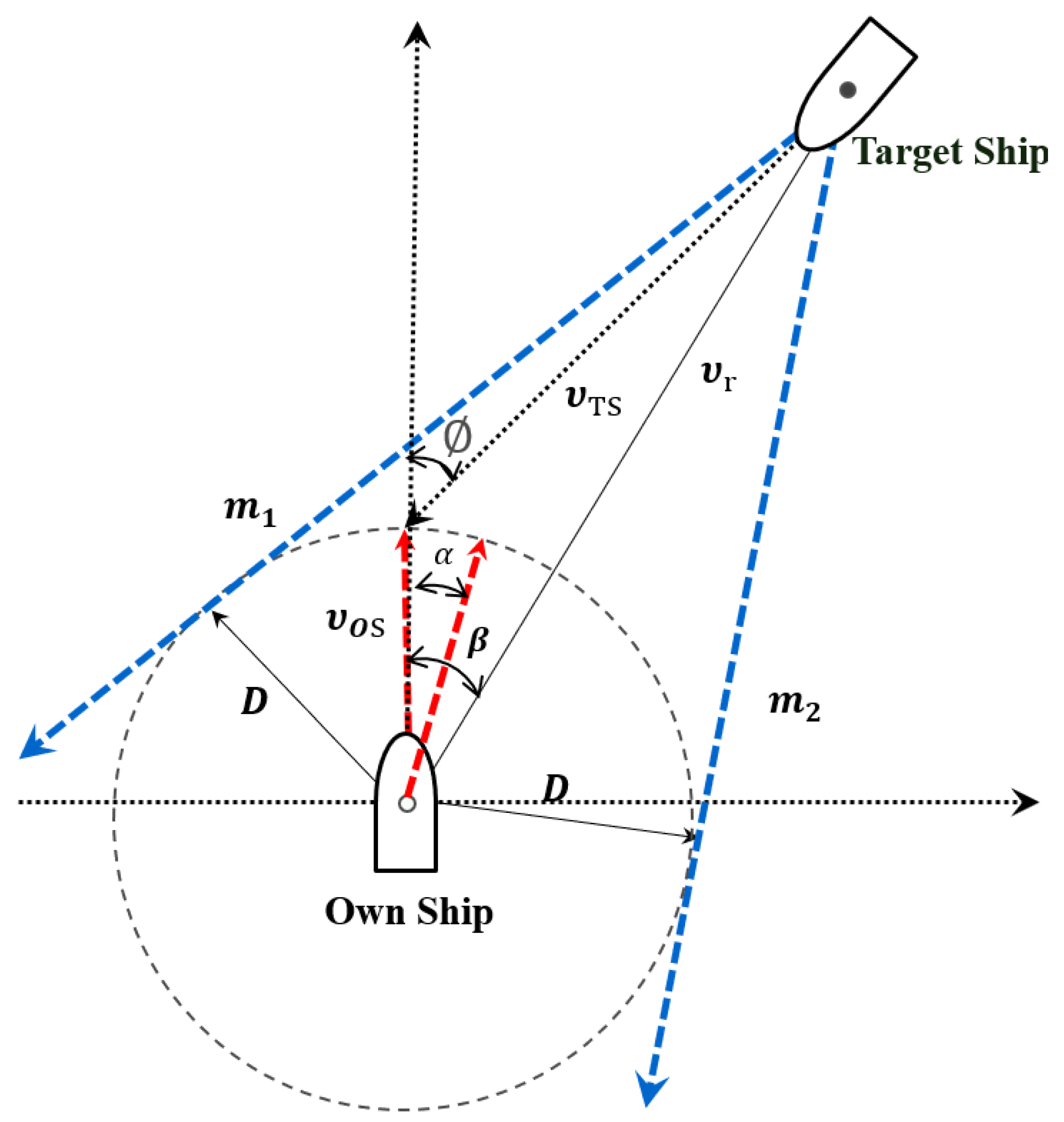
First, the concept of a ship domain proposed by Fujii and Tanaka [25] was employed in studies related to collision risk assessment to evaluate the collision risk. This concept was later carried forward in various forms by Goodwin [26], Davis [27], and Coldwell [28]. With the development of electronic navigation equipment, the use of this equipment, such as RADAR and AISs on ships became essential, and collision risk assessment using time to the closest point of approach (TCPA) began to be studied [29]. This concept was extended, and risk indices, such as the relative distance [30] and the velocity ratio [31] for collision cases were introduced. In recent years, ship maneuverability and the encounter angles between ships have been actively researched [32,33,34,35,36]. Many studies were conducted on action lines to identify the risk of a collision and to determine the proper timing of actions to avoid the collision [12,37]. The action line is represented by a line that shows the last chance for the OS to avoid a collision through a CA action [38]. Determining the action line depends on simulations rather than the judgment of an expert, and it has been referred by various terms in the literature, such as the last line of defense, or the critical distance [39]. As shown by several studies on CA, action lines, vessel encounter angles, risk assessments, etc., do not address the question of proper timing. The reason for this is that the timing of ship CA is obtained by actual navigators according to the general customs of seafarers, such as the myths of 3 miles as the minimum visibility distance for sidelights and 6 miles as the minimum visibility distance for mast lights. Furthermore, the numbers for the proper time for CA suggested by empirical numbers or judicial precedents vary with the situation depending on the size and the speed of the ship. Therefore, determining the proper time for CA is based on the relative distance to another ship and the TCPA if the distance of the closest point of approach (DCPA) is close to zero. The reason for utilizing the TCPA is that it is insensitive to the speed and direction of the TSs and OSs, which can yield some distance to the TS if the TCPA is the same [40,41]. The relationship between the Oss and the TSs, the two ships at a risk of collision, is depicted in Figure 1. Based on this, the distance and the direction of these two ships in a CA situation can be derived as follows.
First, the ship proceeds from the point of CA between the OS and the TS at a veering angle α ; the ship movement does not occur in a linear manner until reaching the veering point O S v after time Δ t . Therefore, the ship’s veering has a turning radius of its reach, where the reach is generally approximately as one-to-two times of the ship length. L OS is the length of the OS, R OS is the turning force coefficient of the OS, and Δ t is the time it takes to proceed from the start of the CA action. The CA action is the ship’s movement based on Δ t and α for the OS to avoid the TS.
The distance of collision avoidance position, D pca , is obtained through Equation (1). In other words, D pca is defined as the margin distance required for collision avoidance (here, the intended TCPA is multiplied by the ship’s speed) and the turning delay. The intended TCPA, Δ t , was set as 15 min, as applied multiple times in a number of past studies and cases [42,43,44]. In this study, as described above, reach is 1 to 2 times the length of the ship, meaning R OS , the median value of the reach point range, was set to 1.5. In addition, by dividing the ship’s speed by D pca , T pca , which is defined as the time from the collision point to the point of collision avoidance, can be obtained, as shown in Equation (2).
D pca = R OS L OS + V OS Δ t ,
T pca = R OS L OS + V OS Δ t V OS .
As shown in Figure 1, in the case where the ship’s course is   C OS and the other ship’s course is   C TS , the relative bearing ∅Φ between the ships at the collision point can be calculated by Equation (3), which is as follows,
Φ = { i f   | C TS C OS | < π ,   π | C TS C OS |   i f   | C TS C OS |     π ,   | C TS C OS | π .
Here, the distance D r and the azimuth β between these two ships can be found using Equations (4) and (5), respectively, given that the time until the CA action is T pca .
D r = ( V TS T pca cos + V OS T pca ) 2 + ( V TS T pca sin ) 2 ,
β = { i f   ( V TS T pca cos + V OS T pca ) < 0 ,   π tan 1 V TS T pca sin | ( V TS T pca cos + V OS T pca ) |   i f   ( V TS T pca cos + V OS T pca )     0 ,   tan 1 V TS T pca sin | ( V TS T pca cos + V OS T pca ) | .

2.3. Sufficient Action for Collision Avodiance

As previously discussed, the COLREG requires evasive maneuvers to be actively taken to avoid collisions, and these maneuvers should be performed in an appropriate time under good seamanship [17]. This rule recommends that the extent of the initial response should be based on the subjective judgment along with the experience of the ship operator based on the ship’s operating environment at the time. However, as not all navigators have proper experience in making excellent judgments on evasive maneuvers, providing sufficient evasive maneuvers and initial deflection angles can thereby contribute to the prevention of these ship collisions. To solve this problem, many studies have been conducted on CA methods; these methods involve the departing of ships (manned or unmanned) from their planned trajectory to avoid potential undesired physical contacts with other ships [12]. Yim and Park [45] obtained the minimum distance for CA via regression analysis. Ahn et al. [46] proposed a collision prevention method using fuzzy logic which used the ship’s length, speed, DCPA, and TCPA for CA. Recently, algorithms incorporating AI technologies have been employed to demonstrate how to avoid collisions [47,48]. These studies arbitrarily selected and used ship-to-ship transverse distances for passage under different navigation environments. In this study, the open sea was selected as the navigation environment, and the criteria obtained from actual navigators were reviewed to develop objective criteria for determining the proper time of the initial evasive maneuver and the sufficient evasive maneuver. We examined the subjective criteria for the initial evasive maneuver judgment of the navigators who had already learned the COLREG Rule 8 “Action to avoid collision”. Lee et al. [49] conducted a survey of 192 mariners, including captains, and the resulting minimum safe separation distances are detailed in Table 2.
As shown in Table 2, seafarers perceived the minimum safe separation distance as 1.0 mile, and this trend was characterized by a higher percentage of respondents at lower ranks. The higher the rank, the closer the response to 0.5 mile. Herein, the threshold for the initial evasive maneuver was calculated as 1.0 mile. As shown in Figure 2, this criteria can be observed in the CA maneuver between two ships at a collision risk [50]. With regard to the relationship between the OSs and the TSs, we defined the slope of a tangent to a circle with the radius D as m 1 and m 2 . The calculation of the slope m along the two ships’ course is given by Equation (6).
m = V TS ×   cos V OS V TS × sin .
Here, if the point coordinates of the TS are ( x o , y o ), then the equation of a straight line through the point with a slope m is given by Equation (7).
m x m x t 0 y + y t 0 = 0 .
The perpendicular distance D from the origin in a Cartesian coordinate system X Y to the straight line given above can be calculated using Equations (8) and (9) below,
D   = m x t 0 + y t 0 m 2 + 1 ,
m = 2 x t 0 y t 0   ±   ( 2 x t 0 y t 0 ) 2 4 ( D 2 x t 0 2 ) ( D 2 y t 0 2 ) 2 ( D 2 x t 0 2 ) .
Here, given the point coordinates of the TS and the value of the distance D , we can find the slope m . An m with a value of >0 indicates that the TS is approaching from the starboard side of the OS, while an m with a value of <0 indicates that the TS is approaching from the port side of the OS. Additionally, two slope values— m 1 and m 2 —were obtained, and if | m 1 | < | m 2 | , this indicates that m 1 corresponds to the TS passing the port side of the OS, and m 2 corresponds to the TS passing the starboard side of the OS, respectively.
The slope m (including m 1 and m 2 ) can be represented as follows, using the relative orientation at the point of collision, and the initial deflection angle α using Equations (10) and (11).
m = V TS cos V OS cos α V TS sin V OS sin α ,
V TS ( cos m sin ) = V OS ( cos α m sin α ) .
If we substitute the relative orientation of the collision point , we can obtain the initial deflection angle α using Equation (12); that is, if we use V TS ( cos m sin ) = k , we get the following:
{ i f   m > 0 ,   α = ± cos 1 ( k V OS m 2 + 1 ) tan 1 ( m )   i f   m < 0 ,   α = ± sin 1 ( k V OS m 2 + 1 ) + tan 1 ( 1 m ) ,
where 180 ° < α < 180 ° .
Herein, D was calculated to be 1.0 mile, which is consistent with the results of a previous study [49].

2.4. Use of Artificial Neural Networks (ANNs)

Several studies have been conducted on detecting and avoiding collision risks. Previously, studies using the fuzzy theory were primarily conducted. Hasegawa [51] attempted to model the degree of collision risk using a fuzzy inference system with the TCPA and DCPA values.
In recent years, many studies on the CA maneuver and the course prediction of ships have been conducted using ANNs [46,52,53]. This is because ANNs have an extremely high ability to learn complex relationships from imprecise data. Moreover, they can be employed to extract the patterns and detect the trends that are too complex for humans or other computer technologies to recognize. They are thought to be a versatile and powerful way to analyze samples, generalize and predict data, remember the features of the data, and match or connect new data [54]. Thus, a well-trained neural network can be considered as an “expert”.
Neural networks begin with a simple model of the neural organization of the human brain. ANNs are a computational organization that learns from past experiences to make abstract values concrete, thereby providing a way to extract features from uncorrelated data or to generalize results from the inputs that cannot be estimated [55].
Recently, deep learning-based neural networks have been found to exhibit superior performances compared to other machine learning algorithms [56]. Deep neural networks with vast hidden layer structures have solved many problems in neural networks that were previously either unsolved or poorly solved [57]. However, deep learning requires relatively longer computation times than other machine learning models, owing to its deep hidden layer structure. With regard to this, Bayesian inference and regularization were introduced to reduce the computation time while maintaining the predictive power on a deep learning level. The prediction results of the Bayesian neural networks are not significantly different from those of the deep neural networks, but the probability distribution of the Bayesian statistics is used to reduce the computation time [58]. The structure of BRANN’s model is shown in Figure 3. In particular, the models of BRANNs are robust enough to not require the validation procedures needed for regular regression methods. In the supervised learning step, we typically change the weights to reduce the mean squared error. The main problem with these techniques is the possibility of overfitting and overtraining, leading to noise fitting and a loss of generalization of the network. To reduce the likelihood of overfitting, a mathematical technique, known as Bayesian regularization, was developed to convert the non-linear system into a well-defined problem [59,60]. In general, the training step aims to reduce the sum of the squared errors between the model output and the target value. Bayesian regularization is expressed by the following equation:
F = β E d + α E w ,
where F is the objective function, E d is the sum of the squared errors, E w is the sum of the square of the network weights, and α and β are the objective function parameters [60]. Bayesian network weights are considered as random variables; therefore, the density function can be written according to Bay’s rules [61]:
P ( w | D , α ,   β , M ) = P ( D | w ,   β ,   M ) P ( w | α ,   M ) P ( D | α ,   β ,   M ) ,
where w is the vector of network weights, D is the data vector, and M represents the neural network model in use.
Forsee and Hagan [61] proposed an approximation of the Gauss–Newton algorithm using the Levenburg–Marquardt training algorithm, with the assumption that the noise in data is Gaussian. This technique reduces the likelihood of hitting a local minima, increasing the generalizability of the network. Although this technique has the advantage of knowing the probabilistic nature of the network weights associated with a given dataset and a model framework, the size of the neural network increases with the additional hidden layer of neurons, dramatically increasing the likelihood of overfitting and requiring a validation set to determine the stopping point. In Bayesian regularized networks, overly complex models are penalized by effectively treating the unnecessary linkage weights as zero. The network is computed and trained with non-trivial weights, known as the effective number of parameters. This converges to a constant as the network grows [59]. This allows for a more compact network that reduces the likelihood of overfitting, while also increasing the data available for training by eliminating the need for a validation step.
Herein, the Levenburg–Marquardt training algorithm was employed to determine the proper time and sufficient actions for a ship to avoid a collision using a BRANN, which improves on the Levenburg–Marquardt training algorithm, reduces the likelihood of overfitting, and reduces the need for a validation phase.

3. Determining the Proper Time and Action of Evasive Maneuver Using ANNs

Herein, an ANN was designed by applying the above-mentioned methods to determine the proper time and sufficient actions for avoiding ship collisions. The designed neural network was validated by calculating the mean squared errors (MSEs). Moreover, the controller designed using the ANN was verified by changing the OS speed, OS length, and TS course (the relative position of the OS and the TS).

3.1. Design of an ANN

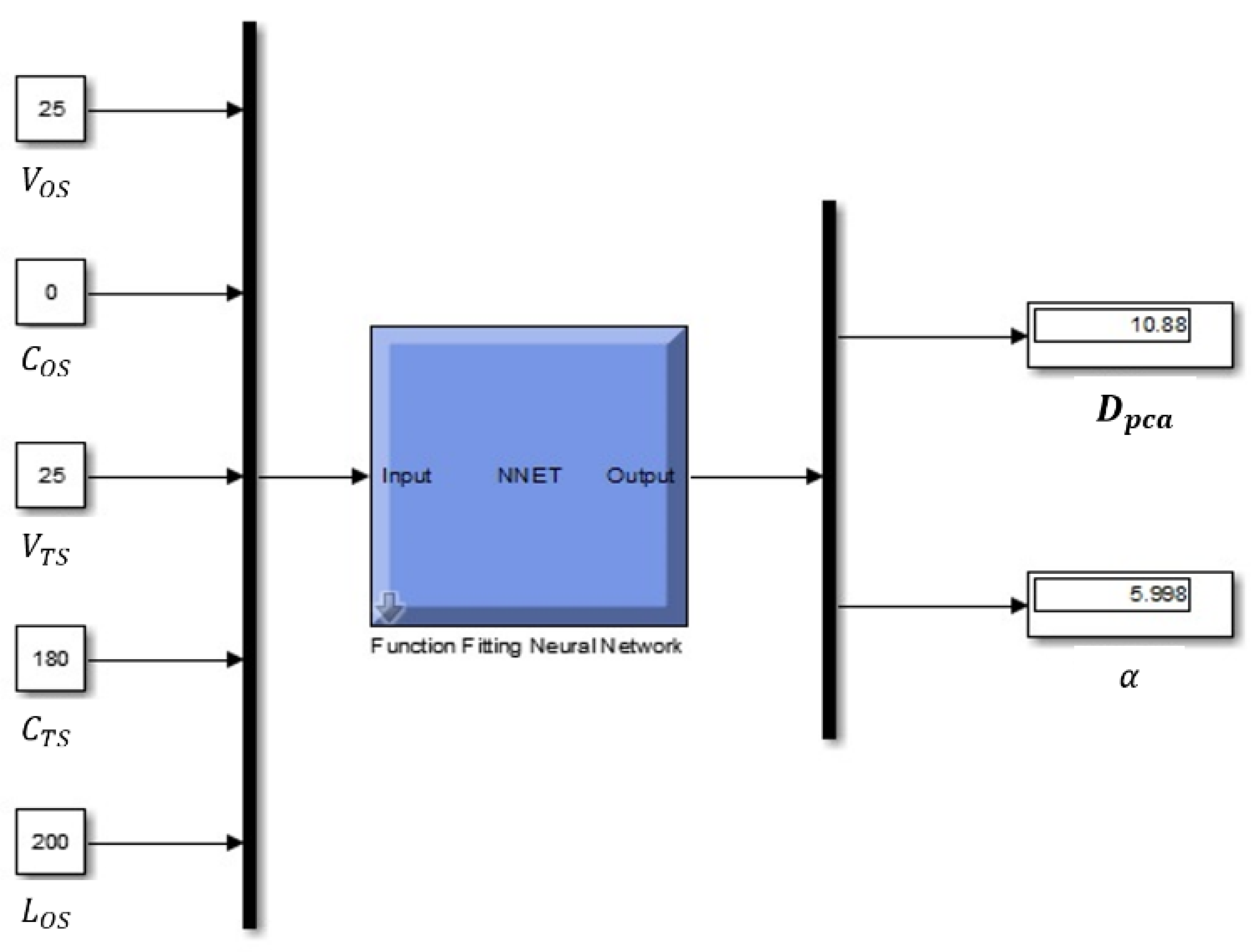
An ANN was designed to determine the proper time and sufficient maneuver for avoiding ship collisions. In this study, from the information obtained by employing the commonly used navigation equipment, such as RADAR and AISs, five parameters were considered as inputs with regard to CA: OS course ( C OS ); OS speed ( V OS ) ; TS course ( C TS ) ; TS speed ( V TS ) ; and OS length ( L OS ) . Based on these input values, the following two parameters were selected as the outputs: CA timing ( D pca ) and the initial deflection angle ( α ). Considering this, the inputs and outputs of the controller designed using the neural network were configured, as shown in Figure 4.
To train the configured neural network, a training data model was built. The five inputs were obtained using the following rules, and the two outputs were calculated using the methodology described previously in Section 2:
  • C OS and C TS were obtained at 30° intervals from 000° to 330°, respectively;
  • V OS and V TS were obtained in five-knot intervals from 10 to 25 knots, respectively;
  • L OS was obtained in 50 m intervals from 100 to 200 m, respectively;
  • The configuration is limited to cases where the ship is performing evasive maneuvers; therefore, only the following cases are considered: the ships encounter each other head-on, the ships overtake each other, and when the TS is on the starboard side of the OS in the case of crossing;
  • When overtaking another ship in front, the difference in their speeds is not large enough to meet the TCPA of 15 min and the passage distance of 1 mile; therefore, this case was not included in this study.
Based on the above rules for generating inputs, 3816 case data were generated. Table 3 partially summarizes these inputs and the outputs that were calculated using these inputs.
We used 70% (2672) of the generated data as the training data, 15% (572) as the validation data, and 15% (572) as the testing data, respectively. Moreover, BRANNs were designed as a neural network with ten hidden nodes in one hidden layer.

3.2. Analysis Results of the ANN

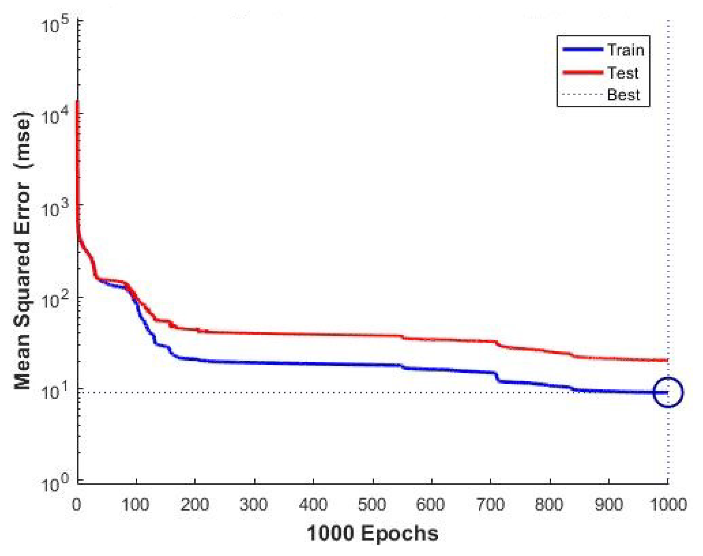
The number of epochs is an important part to solve the problem of the overfitting and underfitting of the dataset. To ensure the sufficient convergence of training, the batch size was set to 100 and the epochs to 1000 in this study [62], among which the weight with the lowest MSE value was designed with, and the MSE value of 9.0745, as shown in Figure 5.
To verify the controller results, they were compared with the calculation results using the following rules:
  • C TS was validated at 3° intervals from 180° to 330°, respectively, to determine changes in the encounter angle between the OS and the TS;
  • V OS was validated in 0.2 knot increments from 15 to 25 knots, respectively;
  • L OS was validated in 2 m intervals from 150 to 250 m, respectively.

3.2.1. Result of the Encounter Angle of the OS with the TS

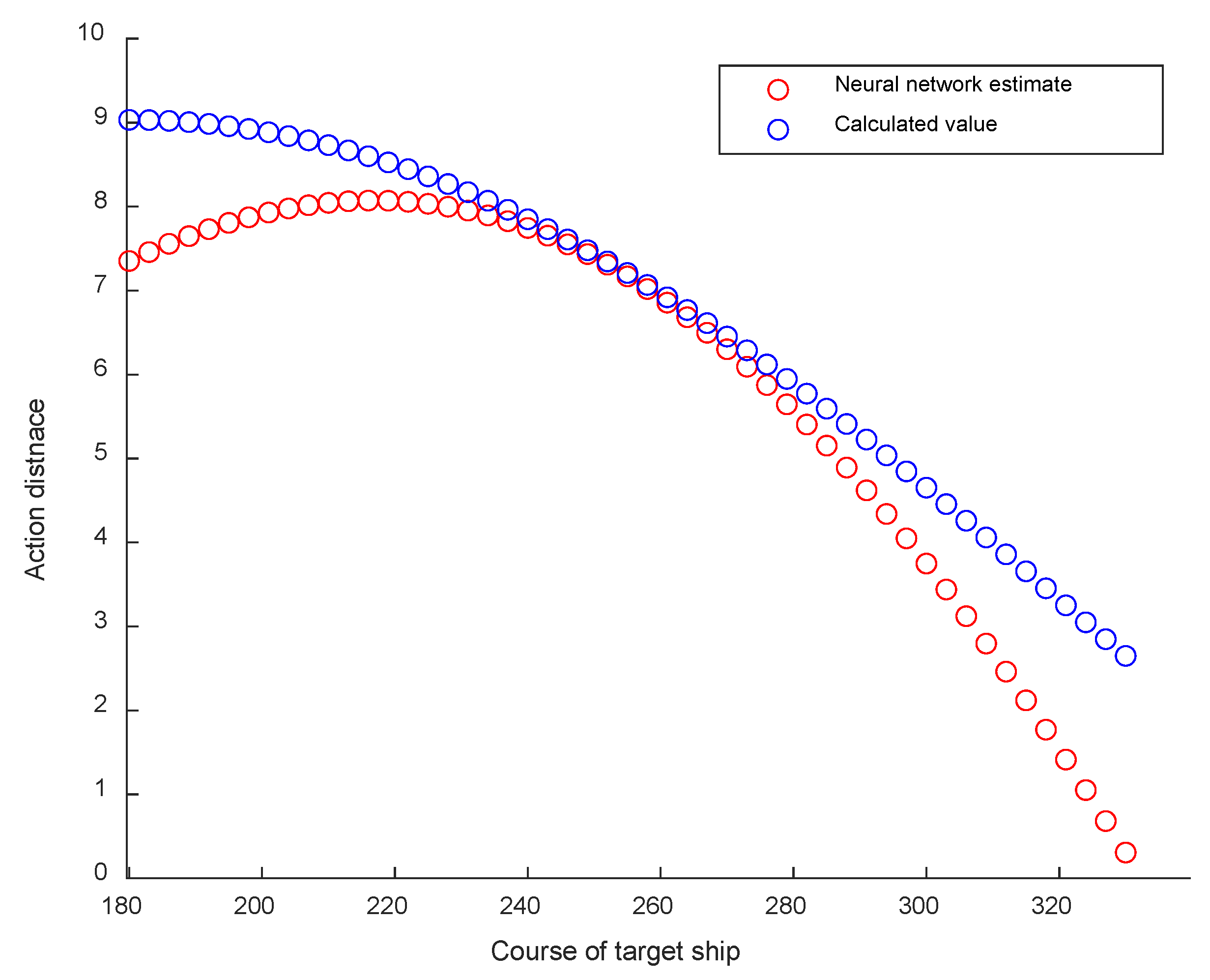
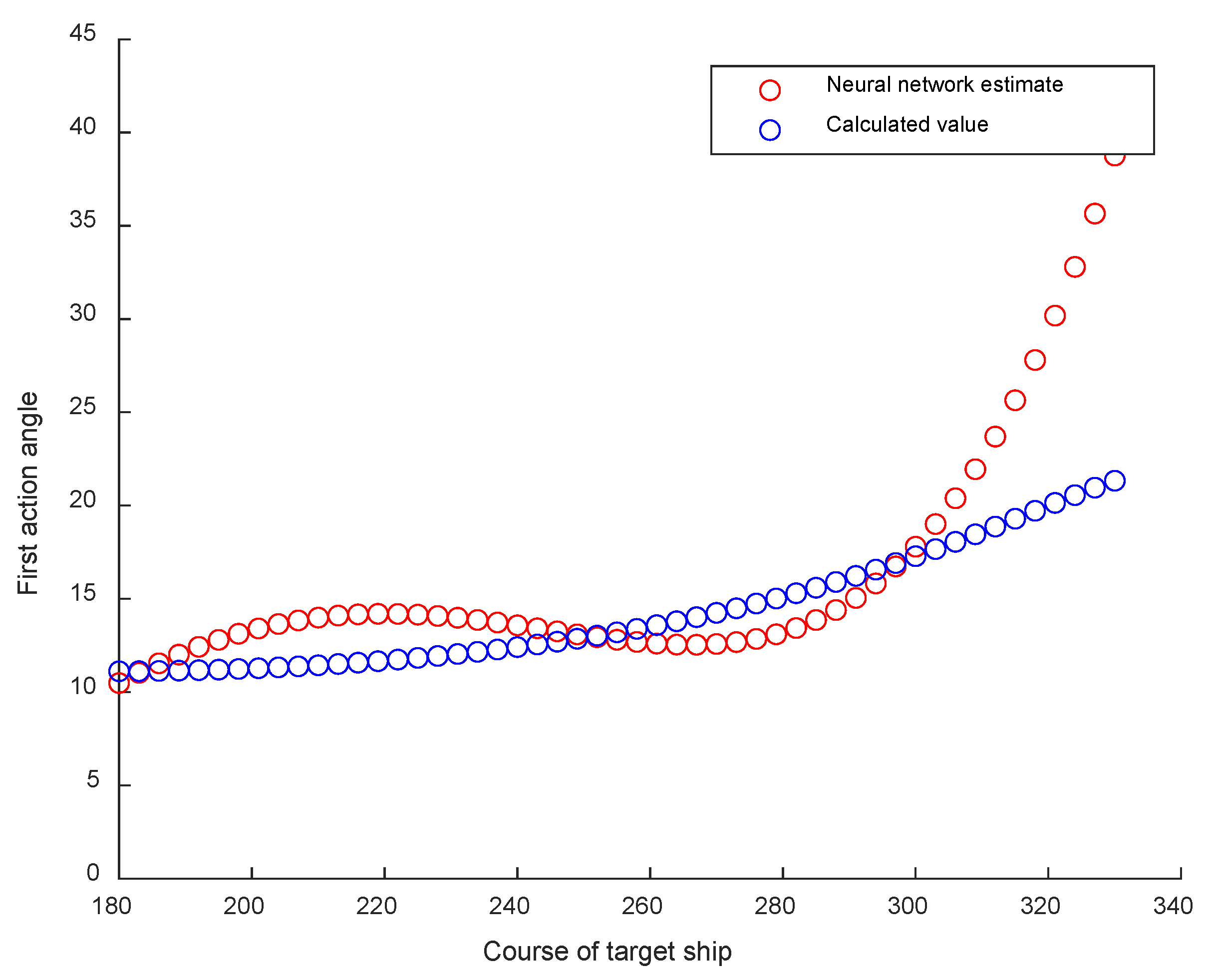
Figure 6 and Figure 7 show a comparison of the calculated values of the proper time and the sufficient maneuver for ship CA as the TS course changed from 180° to 330° in 3° intervals, respectively, with the corresponding values of the controller designed in this study. As shown in Figure 6, with regard to the proper time, the difference between the calculated and the corresponding controller values was the smallest at a TS course of 252°. Additionally, this difference increased when the OS was closer to the TS or closer to overtaking. Specifically, we found an error of approximately 2.34 miles at 330°, which was caused by the relatively short distance between the two ships, despite being based on a sufficient time. Moreover, in this case, a larger angle was required, and sometimes it was deemed to be necessary to turn to the other side. As shown in Figure 7, the sufficient maneuvers showed a close match until the TS course was between 180° and 310°, respectively, after which the error increased considerably as the ships approached the overtaking situation. This error was deemed to be likely due to the short relative distance between these two ships resulting in a large deflection angle, as discussed earlier.
As the TS course changed from 180° to 330° at 3° intervals, respectively, the controller began the CA at approximately 0.74 mile later than the calculated value but deflected approximately 2.72° more than the required deflection angle for a sufficient maneuver, which was thereby considered as a good overall design.

3.2.2. Result of Changing the OS Speed

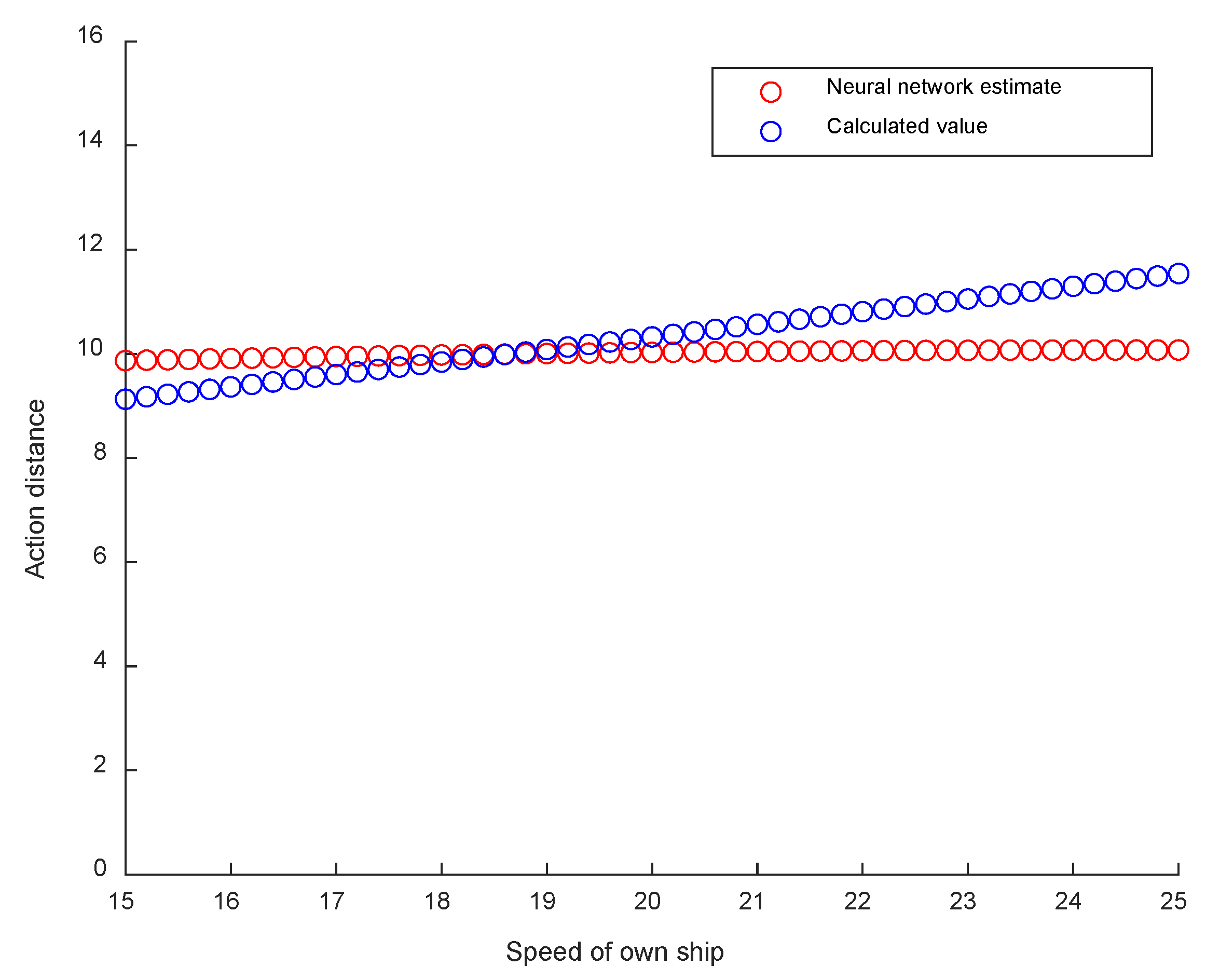
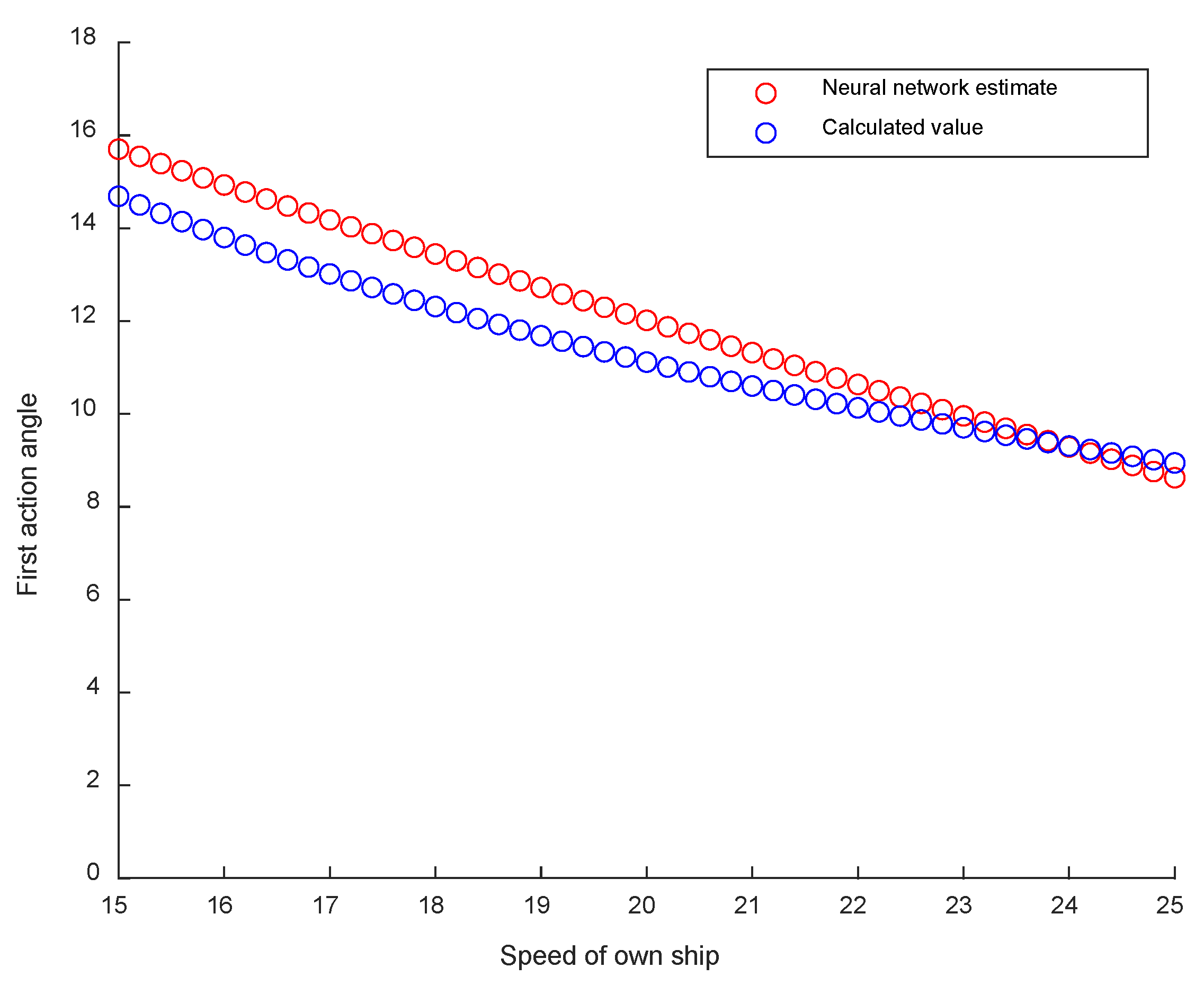
Figure 8 and Figure 9 show a comparison of the calculated values of the proper time and the sufficient maneuver for ship CA with the corresponding values of the controller designed in this study as the OS speed varied from 15 to 25 knots in 0.2 knot increments, respectively. As shown in Figure 8, with regard to the proper time, the difference between the calculated value and the corresponding controller value was approximately 0.008 miles at an OS speed of 18.6 knots, which was found to be the smallest error. This error increases as the OS speed decreases or increases. Specifically, at 25 knots, we found an error of approximately 1.47 miles. We believe that this error was formed due to the fact that as the difference between the speeds of the two ships increases, their relative velocity increases and their maneuver becomes faster as a result. As shown in Figure 9, with regard to the sufficient maneuver, the difference between the calculated and the corresponding controller values was determined to be the smallest (approximately 0.038°) at an OS speed of 23.8 knots. Although these two values do not have a considerable error, the error increased slightly as the OS speed decreases. We believe that this error was due to the fact that as the difference between the speeds of these two ships increases, the proper time is accelerated as a result, requiring more initial maneuvers.
The controller was confirmed to be well designed overall, as the corresponding proper time for CA was only approximately 0.60 mile later compared to the calculated value for the OS speed varying from 15 to 25 knots in 0.2 knot increments, while the deflection angle required for the sufficient maneuver was approximately 0.75° more than the corresponding calculated value, respectively.

3.2.3. Result of Changing the OS Length

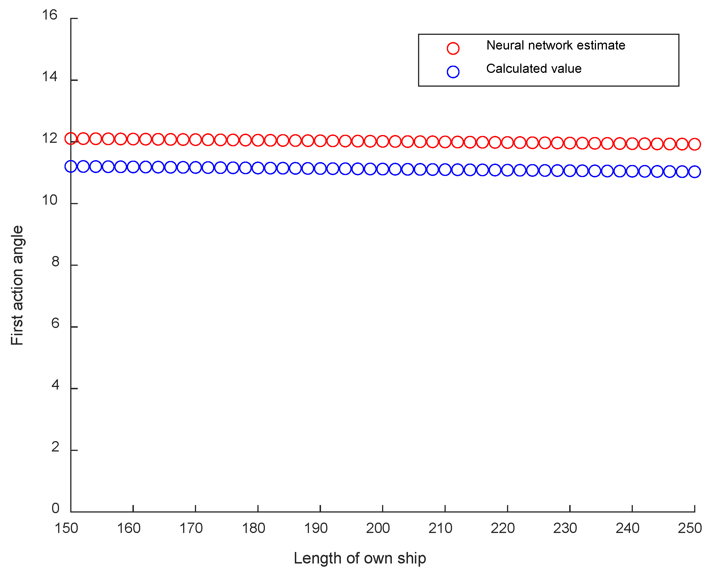
Figure 10 and Figure 11 show the calculated values of the proper time and sufficient maneuver for ship CA as the OS length varied from 150 to 250 m in 2 m intervals, respectively; these values were compared with the corresponding values of the controller designed in this study. The error between the calculated and the corresponding controller values was found to be almost constant; the difference was not substantial. This was believed to be the result of a proportional increase in the proper time and the sufficient maneuver with the OS length.
As the OS length varied in 2 m intervals from 150 to 250 m, the proper time for CA was found to approximately be 0.30 mile later compared to the calculated value, while the deflection angle required for the sufficient maneuver was found to be approximately 0.90° more, respectively, suggesting that the overall design is good.

4. Discussion

4.1. Research Validation

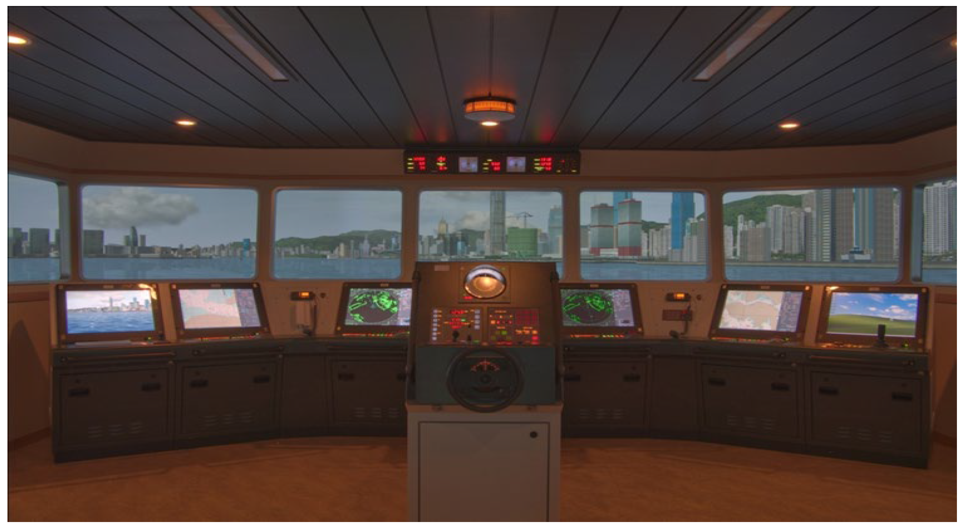
To verify the performance of the controller designed herein, the full-mission ship-handling simulator of the Korea Institute of Maritime and Fisheries Technology (KIMFT) was employed (Navi-Trainer Professional 5000 from Wärtsilä as a navigational simulator) (Figure 12). KIMFT’s simulators meet the DNV class A code and are equipped with 360° visual projection and shipborne equipment. Thus, they are employed for research, as well as for the training of captains and pilots. Moreover, these simulators can store and analyze important data, such as the position, course, and speed of ships used in simulation exercises [63].
The ship used to verify the performance of this controller was a container ship with a length of 203.6 m, a width of 25.4 m, and a maximum speed of 19.4 knots. Other details of this ship and simulation conditions are summarized in Table 4.
To verify the controller via simulation, four scenarios were considered. Each scenario was simulated by calculating the proper time and the sufficient maneuver for CA using the controller in advance, as shown in Table 5.
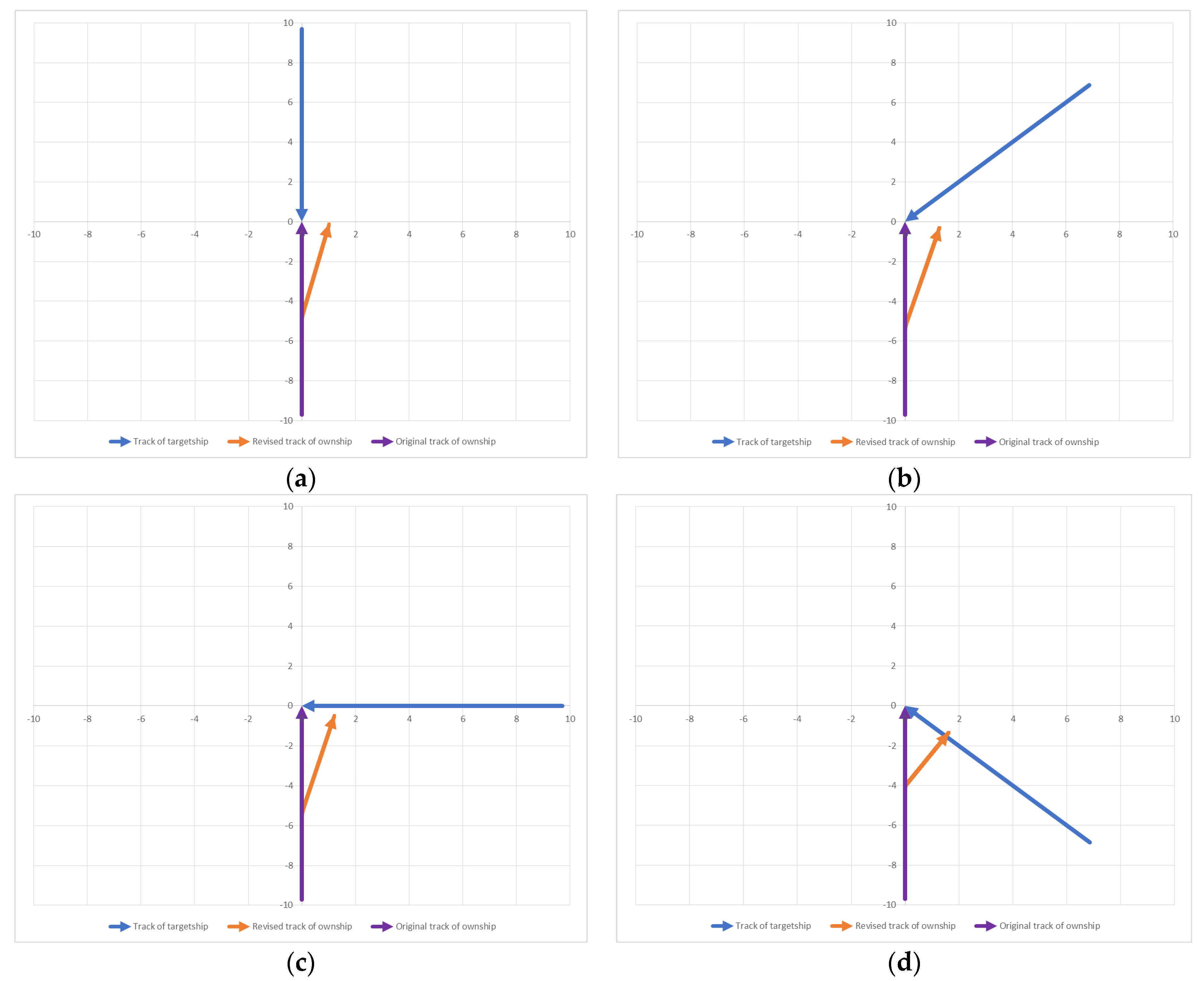
Simulations were conducted using a container ship for the four scenarios. For each scenario, a precalculated CA maneuver was performed using the controller at the proper time. In particular, the ship’s course was changed while maintaining a turning rate of 10°/min, which is the turning rate that is typically used when the ship is maneuvered safely (except in special cases) [63]. After performing these simulations, the obtained data were used to measure the closest point of approach (CPA) between the two ships. The navigation of the ship according to these simulations is shown in Figure 13; the detailed results are presented in Table 5.
As shown in Case 3, Table 6, right-angle crossing exhibited the smallest error between the intended passage distance and the simulation-validated CPA; the error between the two CPAs for each scenario was approximately −0.18–0.22 miles, indicating that the proper time and sufficient maneuver for CA recommended by the controller has been validated.

4.2. Research Contributions

The contributions of this research can be summarized as follows.
Herein, a controller was designed using a neural network to propose the proper time of the evasive maneuver and the sufficient maneuver for ship CA, which were proposed via regression analysis conducted by previous studies. The proposed proper time of the evasive maneuver and the sufficient maneuver were validated through simulations. It is anticipated that this controller will be able to provide guidance to inexperienced seafarers for avoiding ship collisions by utilizing these suggested evasive and sufficient maneuvers. The provision of such guidance will contribute considerably to the prevention of ship collisions at sea.
Moreover, the controller proposed in this study can further contribute to the development of an alarm system to avoid missing the proper time for an evasive maneuver and an autonomous ship collision–avoidance system, such as a ship’s autopilot.
This study is somewhat limited in the case of overtaking a ship in front and other similar cases as the distance between the two ships was smaller than the distance to ensure safety, despite the sufficient time suggested in the previous study being applied. However, if further research is conducted to examine the CPA and the TCPA of overtaking, and if criteria for appropriate overtaking distances by surveying experienced seafarers is established, it may be possible to train the neural network controller in a way similar to that used in this work for further improving it.

5. Conclusions

Ship collisions at sea constitute a major maritime accident, causing the loss of lives and properties. After investigating and analyzing maritime accidents, it was found that ship collisions are caused by either missing the timing of a maneuver or not taking enough maneuvers. Therefore, the objectives of this research were to recognize the limitations in providing quantitative numbers for ship CA and to design a neural network controller that provides the proper time and sufficient maneuvers for CA in accordance with the COLREG rules. The data for training, validating, and assessing BRANNs were prepared by calculating the proper time of the evasive maneuver and the sufficient maneuver based on previous studies. Finally, an ANN controller was designed, and this designed controller was successfully verified via simulations.
The contributions and limitations of this study can be summarized as follows. The controller proposed in this study will be able to prevent ship collisions by suggesting the proper time for the evasive maneuver and sufficient actions for inexperienced seafarers. It has also been anticipated that this controller will contribute to CA warning systems, course-maintaining equipment, such as ship autopilots, and CA maneuvering systems for autonomous ships. This study is however limited for cases such as overtaking a ship in front. However, it is expected that the controller will be further improved by establishing criteria for the appropriate overtaking distance after further examining the CPA and TCPA for overtaking using the method presented in this study.

Author Contributions

Conceptualization, J.-K.K.; methodology, J.-K.K. and D.-J.P.; software, J.-K.K.; validation, D.-J.P.; investigation, J.-K.K.; data curation, J.-K.K.; writing—original draft preparation, J.-K.K.; writing—review and editing, D.-J.P.; visualization, J.-K.K.; supervision, D.-J.P.; funding acquisition, D.-J.P. All authors have read and agreed to the published version of the manuscript.

Funding

This research was funded by the National Research Foundation of Korea grant supported by the Korea government, grant number 2022R1F1A1070331.

Institutional Review Board Statement

Not applicable.

Conflicts of Interest

The authors declare no conflict of interest.

References

  1. European Maritime Safety Agency. Annual Overview of Marine Casualties and Incidents in 2022; EMSA: Lisbon, Portugal, 2022; pp. 1–62.
  2. Marine Transportation Occurrences in 2020. Available online: https://www.bst-tsb.gc.ca/eng/stats/marine/2021/ssem-ssmo-2021.html (accessed on 16 February 2023).
  3. JTSB Japan Transport Safety Board, Statistics of Marine Accident. Available online: http://www.mlit.go.jp/jtsb/statistics_mar.html (accessed on 16 February 2023).
  4. Negenborn, R.R.; Goerlandt, F.; Johansen, T.A.; Slaets, P.; Banda, O.A.V.; Vanelslander, T.; Ventikos, N.P. Autonomous ships are on the horizon: Here’s what we need to know. Nature 2023, 615, 30–33. [Google Scholar] [CrossRef] [PubMed]
  5. Puisa, R.; McNay, J.; Montewka, J. Maritime safety: Prevention versus mitigation? Saf. Sci. 2021, 136, 105151. [Google Scholar] [CrossRef]
  6. Puisa, R.; Lin, L.; Bolbot, V.; Vassalos, D. Unravelling causal factors of maritime incidents and accidents. Saf. Sci. 2018, 110, 124–141. [Google Scholar] [CrossRef] [Green Version]
  7. Chin, H.C.; Debnath, A.K. Modeling perceived collision risk in port water navigation. Saf. Sci. 2009, 47, 1410–1416. [Google Scholar] [CrossRef] [Green Version]
  8. Di Pasquale, V.D.; Miranda, S.; Iannone, R.; Riemma, S. A simulator for human error probability analysis (SHERPA). Reliab. Eng. Syst. Saf. 2015, 139, 17–32. [Google Scholar] [CrossRef]
  9. Wróbel, K. Searching for the origins of the myth: 80% human error impact on maritime safety. Reliab. Eng. Syst. Saf. 2021, 216, 107942. [Google Scholar] [CrossRef]
  10. Human Element International Maritime Organization. Available online: https://www.imo.org/en/OurWork/HumanElement/Pages/Default.aspx (accessed on 16 February 2023).
  11. Shaobo, W.; Yingjun, Z.; Lianbo, L. A collision avoidance decision-making system for autonomous ship based on modified velocity obstacle method. Ocean Eng. 2020, 215, 107910. [Google Scholar] [CrossRef]
  12. Huang, Y.; Chen, L.; Chen, P.; Negenborn, R.R.; Van Gelder, P.H.A.J.M. Ship collision avoidance methods: State-of-the-art. Saf. Sci. 2020, 121, 451–473. [Google Scholar] [CrossRef]
  13. Xue, J.; Van Gelder, P.H.A.J.M.; Reniers, G.; Papadimitriou, E.; Wu, C. Multi-attribute decision-making method for prioritizing maritime traffic safety influencing factors of autonomous ships’ maneuvering decisions using grey and fuzzy theories. Saf. Sci. 2019, 120, 323–340. [Google Scholar] [CrossRef]
  14. Wang, T.; Wu, Q.; Zhang, J.; Wu, B.; Wang, Y. Autonomous decision-making scheme for multi-ship collision avoidance with iterative observation and inference. Ocean Eng. 2020, 197, 106873. [Google Scholar] [CrossRef]
  15. Cho, Y.; Han, J.; Kim, J. Efficient COLREG-compliant collision avoidance in multi-ship encounter situations. IEEE Trans. Intell. Transp. Syst. 2020, 23, 1899–1911. [Google Scholar] [CrossRef]
  16. Zhou, X.Y.; Huang, J.J.; Wang, F.W.; Wu, Z.L.; Liu, Z.J. A study of the application barriers to the use of autonomous ships posed by the good seamanship requirement of COLREGs. J. Navig. 2020, 73, 710–725. [Google Scholar] [CrossRef]
  17. Convention on the International Regulations for Preventing Collisions at Sea, 1972 (COLREGs). Available online: https://www.imo.org/en/About/Conventions/Pages/COLREG.aspx (accessed on 16 February 2023).
  18. Wróbel, K.; Gil, M.; Huang, Y.; Wawruch, R. The vagueness of COLREG versus collision avoidance techniques—A discussion on the current state and future challenges concerning the operation of autonomous ships. Sustainability 2022, 14, 16516. [Google Scholar] [CrossRef]
  19. Zupan, J. Introduction to artificial neural network (ANN) methods: What they are and how to use them. Acta Chim. Slov. 1994, 41, 327–352. [Google Scholar]
  20. Macrae, C. Human factors at sea: Common patterns of error in groundings and collisions. Marit. Policy. Manag. 2009, 36, 21–38. [Google Scholar] [CrossRef]
  21. Kim, D. A study on factors that trigger human errors related to causes of ship collisions. J. Korean Soc. Mar. Environ. Saf. 2017, 23, 801–809. [Google Scholar] [CrossRef]
  22. Zhang, J.; Zhang, D.; Yan, X.; Haugen, S.; Guedes Soares, C.G. A distributed anti-collision decision support formulation in multi-ship encounter situations under COLREGs. Ocean Eng. 2015, 105, 336–348. [Google Scholar] [CrossRef]
  23. Chauvin, C.; Clostermann, J.P.; Hoc, J.M. Impact of training programs on decision-making and situation awareness of trainee watch officers. Saf. Sci. 2009, 47, 1222–1231. [Google Scholar] [CrossRef]
  24. Kuchar, J.K.; Yang, L.C. A review of conflict detection and resolution modeling methods. IEEE Trans. Intell. Transp. Syst. 2000, 1, 179–189. [Google Scholar] [CrossRef] [Green Version]
  25. Fujii, Y.; Tanaka, K. Traffic capacity. J. Navig. 1971, 24, 543–552. [Google Scholar] [CrossRef]
  26. Goodwin, E.M. A statistical study of ship domains. J. Navig. 1975, 28, 328–344. [Google Scholar] [CrossRef] [Green Version]
  27. Davis, P.V.; Dove, M.J.; Stockel, C.T. A computer simulation of marine traffic using domains and areas. J. Navig. 1980, 33, 215–222. [Google Scholar] [CrossRef]
  28. Coldwell, T.G. Marine traffic behavior in restricted waters. J. Navig. 1983, 36, 430–444. [Google Scholar] [CrossRef]
  29. Hara, K.; Hammer, A. A Safe Way of Collision Avoidance Maneuver Based on Maneuvering Standard Using Fuzzy Reasoning Model. In Proceedings of the International Conference on Marine Simulation and Ship Manoeuvrability, St. John’s, NF, Canada, 26 September–20 October 1993. [Google Scholar]
  30. Li, B.; Pang, F.W. An approach of vessel collision risk assessment based on the D–S evidence theory. Ocean Eng. 2013, 74, 16–21. [Google Scholar] [CrossRef]
  31. Gang, L.; Wang, Y.; Sun, Y.; Zhou, L.; Zhang, M. Estimation of vessel collision risk index based on support vector machine. Adv. Mech. Eng. 2016, 8, 1687814016671250. [Google Scholar] [CrossRef] [Green Version]
  32. Wang, X.; Liu, Z.; Cai, Y. The ship maneuverability based collision avoidance dynamic support system in close-quarters situation. Ocean Eng. 2017, 146, 486–497. [Google Scholar] [CrossRef]
  33. Vestre, A.; Bakdi, A.; Vanem, E.; Engelhardtsen, Ø. AIS-based near-collision database generation and analysis of real collision avoidance manoeuvres. J. Navig. 2021, 74, 985–1008. [Google Scholar] [CrossRef]
  34. Przywarty, M.; Boć, R.; Brcko, T.; Perkovič, M. Factors influencing the action point of the collision avoidance manoeuvre. Appl. Sci. 2021, 11, 7299. [Google Scholar] [CrossRef]
  35. Piskur, P.; Szymak, P.; Jaskólski, K.; Flis, L.; Gąsiorowski, M. Hydroacoustic System in a Biomimetic Underwater Vehicle to Avoid Collision with Vessels with Low-Speed Propellers in a Controlled Environment. Sensors 2020, 20, 968. [Google Scholar] [CrossRef] [Green Version]
  36. Jaskólski, K.; Felski, A.; Piskur, P. The Compass Error Comparison of an Onboard Standard Gyrocompass, Fiber-Optic Gyrocompass (FOG) and Satellite Compass. Sensors 2019, 19, 1942. [Google Scholar] [CrossRef] [Green Version]
  37. Park, S.H. A study on the application of navigation rules: Focused on maritime safety tribunal decision case. Korea Inst. Marit. Law 2018, 30, 131–154. [Google Scholar] [CrossRef]
  38. Szlapczynski, R.; Krata, P.; Szlapczynska, J. Ship domain applied to determining distances for collision avoidance manoeuvres in give-way situations. Ocean Eng. 2018, 165, 43–54. [Google Scholar] [CrossRef]
  39. Krata, P.; Montewka, J. Assessment of a critical area for a give-way ship in a collision encounter. Arch. Transp. 2015, 34, 51–60. [Google Scholar] [CrossRef] [Green Version]
  40. Koszelew, J.; Wołejsza, P. Determination of the last moment manoeuvre for collision avoidance using standards for ships manoeuvrability. Annu. Navig. 2017, 24, 301–313. [Google Scholar] [CrossRef] [Green Version]
  41. Shah, B.C.; Švec, P.; Bertaska, I.R.; Sinisterra, A.J.; Klinger, W.; von Ellenrieder, K.; Dhanak, M.; Gupta, S.K. Resolution-adaptive risk-aware trajectory planning for surface vehicles operating in congested civilian traffic. Auton. Robot. 2016, 40, 1139–1163. [Google Scholar] [CrossRef]
  42. Li, W.; Zhong, L.; Xu, Y.; Shi, G. Collision risk index calculation based on an improved ship domain model. J. Mar. Sci. Eng. 2022, 10, 2016. [Google Scholar] [CrossRef]
  43. Banaś, P.; Pietrzykowski, Z.; Wójcik, A.; Wołejsza, P. Automation of processes of identifying navigation situations requiring communication to be established by a sea-going vessel. Zesz. Nauk. Akad. Morskiej W Szczecinie 2013, 36, 15–21. [Google Scholar]
  44. Kang, L.; Lu, Z.; Meng, Q.; Gao, S.; Wang, F. Maritime simulator based determination of minimum DCPA and TCPA in head-on ship-to-ship collision avoidance in confined waters. Transp. A 2019, 15, 1124–1144. [Google Scholar] [CrossRef]
  45. Yim, J.B.; Park, D.J. Modeling evasive action to be implemented at the minimum distance for collision avoidance in a give-way situation. Ocean Eng. 2022, 263, 112210. [Google Scholar] [CrossRef]
  46. Ahn, J.H.; Rhee, K.P.; You, Y.J. A study on the collision avoidance of a ship using neural networks and fuzzy logic. App. Ocean Res. 2012, 37, 162–173. [Google Scholar] [CrossRef]
  47. Sawada, R.; Sato, K.; Majima, T. Automatic ship collision avoidance using deep reinforcement learning with LSTM in continuous action spaces. J. Mar. Sci. Technol. 2021, 26, 509–524. [Google Scholar] [CrossRef]
  48. Xie, S.; Garofano, V.; Chu, X.; Negenborn, R.R. Model predictive ship collision avoidance based on Q-learning beetle swarm antenna search and neural networks. Ocean Eng. 2019, 193, 106609. [Google Scholar] [CrossRef]
  49. Lee, Y.S.; Park, J.M.; Lee, Y.J. A study on the initial action of navigators to avoid risk of collision at sea. J. Navig. Port. Res. 2014, 38, 327–333. [Google Scholar] [CrossRef] [Green Version]
  50. Yang, H.S. A study on the ship collision avoidance model considered speed. J. Korean Inst. Navig. Port Res. 2006, 30, 779–785. [Google Scholar] [CrossRef]
  51. Hasegawa, K. Automatic collision avoidance system for ships using fuzzy control. Nav. Arch. J. 1987, 205, 1–10. [Google Scholar]
  52. Tang, H.; Yin, Y.; Shen, H. A model for vessel trajectory prediction based on long short-term memory neural network. J. Mar. Eng. Technol. 2022, 21, 136–145. [Google Scholar] [CrossRef]
  53. Simsir, U.; Ertugrul, S. Prediction of manually controlled vessels’ position and course navigating in narrow waterways using artificial neural networks. Appl. Soft. Comput. 2009, 9, 1217–1224. [Google Scholar] [CrossRef]
  54. Ertugrul, S.; Hizal, N.A. Neuor-fuzzy controller design via modeling human operator actions. J. Intell. Fuzzy Syst. 2005, 16, 133–140. [Google Scholar]
  55. Kwak, M.K.; Suh, S.H. Design of neural-network based autopilot control system(I). J. Soc. Nav. Archit. Korea 1997, 34, 56–63. [Google Scholar]
  56. Skansi, S. Introduction to Deep Learning: From Logical Calculus to Artificial Intelligence; Springer: Cham, Switzerland, 2018. [Google Scholar]
  57. Goodfellow, I.; Bengio, Y.; Courville, A. Deep Learning; MIT Press: Cambridge, MA, USA, 2016. [Google Scholar]
  58. Jun, S. Regression machine learning using Bayesian inference and regularization. J. Korean Inst. Intell. Syst. 2019, 29, 390–394. [Google Scholar] [CrossRef]
  59. Burden, F.; Winkler, D. Bayesian regularization of neural networks. Methods Mol. Biol. 2008, 458, 25–44. [Google Scholar] [CrossRef] [PubMed]
  60. MacKay, D.J.C. A practical Bayesian framework for backpropagation networks. Neural Comput. 1992, 4, 448–472. [Google Scholar] [CrossRef] [Green Version]
  61. Forsee, F.D.; Hagan, M.T. Gauss-Newton approximation to Bayesian learning. In Proceedings of the 1997 IEEE International Conference on Neural Networks 1–4, Houston, TX, USA, 12 June 1997. [Google Scholar]
  62. Hupponen, K. A Simulator for Evaluating Machine-Learning Algorithms for Autonomous Ships. Master’s Thesis, Abo Akademi, Turku, Finland, 2020. [Google Scholar]
  63. Japan Captains’ Association. A Guide to Ship Handling/The Best Seamanship; International Mariners Management Association of Japan: Tokyo, Japan, 2009. [Google Scholar]
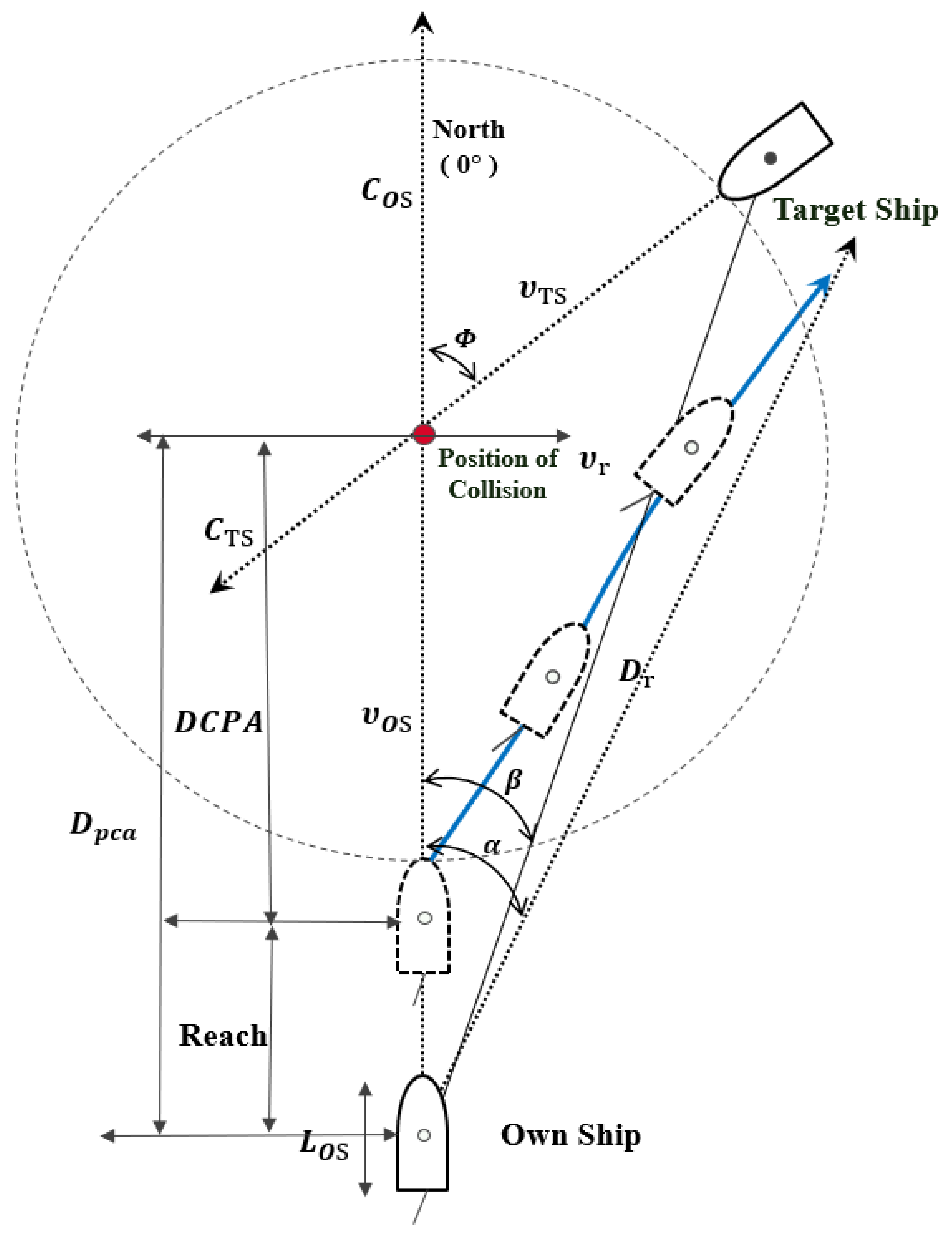
Figure 1. Coordinate system of a collision situation between the own ship (OS) and the target ship (TS). (red is position of collision and blue line is own ship’s avoiding action line).
Jmse 11 01384 g001
Figure 2. Coordinate system for a collision avoidance action between the OS and the TS.
Jmse 11 01384 g002
Figure 3. Structure of a Bayesian regularized artificial neural network (BRANN).
Jmse 11 01384 g003
Figure 4. Construction of a controller using BRANNs.
Jmse 11 01384 g004
Figure 5. Graph of the best training performance for 1000 epochs.
Jmse 11 01384 g005
Figure 6. Action distance for collision avoidance versus the TS course.
Jmse 11 01384 g006
Figure 7. First action angle for collision avoidance versus the TS course.
Jmse 11 01384 g007
Figure 8. Action distance for collision avoidance versus the OS speed.
Jmse 11 01384 g008
Figure 9. First action angle for collision avoidance versus the OS speed.
Jmse 11 01384 g009
Figure 10. Action distance for collision avoidance versus the OS length.
Jmse 11 01384 g010
Figure 11. First action angle for collision avoidance versus the OS length.
Jmse 11 01384 g011
Figure 12. Full-mission ship-handling simulator of the Korea Institute of Maritime and Fisheries Technology.
Jmse 11 01384 g012
Figure 13. Simulated tracks of the ship: (ad) Case 1–4, respectively.
Jmse 11 01384 g013
Table 1. Analysis of the situation of collision occurrence.
Related WorkShip’s CodeCourse
(°)
Speed
(Knots)
Ship Length (m)Time of the First Recognition (before Collision)Time of the First Collision Avoidance Action (before Collision)Type of the Avoidance Action
Investigation report of a collision accident (KMST, 150915) A05017.0159.510 min2 minPort steer from 050° to 040°
B27010.7 66.71 min1 minHard a starboard
Investigation report of a collision accident (KMST, 150204)A2136.0 87.824 min4 minHard a port
B02111.5 225.034 min8 minStarboard steer from 021° to 050°
Investigation report of a collision accident (JTSB, MA2019-6)A01212.2397.713 min2 minStop engine and hard a port
B2855.7147.88 min7 minIncreasing speed
Investigation report of a collision accident (JTSB, MA2021-3)A040.618.0338.227 min7 minPort steer from 040.6° to 019.7°
B29013.8141.012 min2 minStarboard 10°
Abbreviations: KMST, Korea Maritime Safety Tribunal; and JTSB, Japan Transport Safety Board.
Table 2. Survey result for the minimum safe distance.
RankThird OfficerSecond OfficerChief OfficerCaptain
Distance
0.5 mile2 (6.9%)13 (21.6%)32 (35.6%)5 (38.5%)
1.0 mile24 (82.8%)46 (76.7%)52 (57.8%)7 (53.8%)
2.0 miles2 (6.9%)1 (1.7%)5 (5.5%)1 (7.7%)
3.0 miles1 (3.4%)0 (0.0%)1 (1.1%)0 (0.0%)
Source: Lee et al. [49].
Table 3. Evaluation of the model.
Case No.InputOutput
V OS   ( Knots ) C OS     ( ° ) V TS     ( Knots ) C TS     ( ° ) L OS   ( m ) D pca   ( Mile ) α
1100153002003.5−122.7
2201201502007.812.4
325180251501003.3−30.0
415300252101507.525.4
51527020901509.014.8
381625330203001003.218.5
With regard to α (°), positive numbers indicate starboard-side deflection, while negative numbers indicate port-side deflection, respectively.
Table 4. Detailed information about the simulation ship and its conditions.
Ship SpecificationsSimulation Condition
Ship typeContainer carrierDepth9.6 mWind force5 knotsVisibility10 miles
Length overall203.6 mDisplacement32,025 tonsWind direction000°Target shipSame as the own ship
Breadth25.4 mShip’s max speed19.4 knotsWave0.4 mRate of turn10°/min
Table 5. Detailed conditions of each simulation scenario.
Scenario V OS     ( Knots ) C OS   ( ° ) V TS     ( Knots ) C TS   ( ° ) L OS   ( m ) D pca   ( Miles ) α
Case 119.400019.4180203.610.012.3
Case 222510.214.4
Case 32707.914.0
Case 43152.426.2
Table 6. Simulation results.
ScenarioOriginal CPA
(Mile)
Passage Distance (D)
(Mile)
Revised CPA by the Controller
(Mile)
Error
(Mile)
Case 101.01.03+0.03
Case 21.22+0.22
Case 30.92−0.08
Case 40.82−0.18
Disclaimer/Publisher’s Note: The statements, opinions and data contained in all publications are solely those of the individual author(s) and contributor(s) and not of MDPI and/or the editor(s). MDPI and/or the editor(s) disclaim responsibility for any injury to people or property resulting from any ideas, methods, instructions or products referred to in the content.