Article

Linear Longitudinal Strength Analysis of a Multipurpose Cargo Ship under Combined Bending and Torsional Load

by
Joynal Abedin
1,
Francis Franklin
1 and
S. M. Ikhtiar Mahmud
2,*
1
School of Engineering, Newcastle University, Newcastle upon Tyne NE1 7RU, UK
2
Department of Naval Architecture and Marine Engineering, Military Institute of Science and Technology, Dhaka 1216, Bangladesh
*
Author to whom correspondence should be addressed.
J. Mar. Sci. Eng. 2024, 12(1), 59; https://doi.org/10.3390/jmse12010059
Submission received: 30 November 2023 / Revised: 19 December 2023 / Accepted: 19 December 2023 / Published: 26 December 2023

Abstract

:
Cargo ships with wide hatches usually have thin walls and limited torsional rigidity. Consequently, conducting a comprehensive torsional analysis is important because these loads can exert a significant impact. In this paper, the structural response of a multipurpose cargo ship to combined bending and torsional loads is studied using finite element analysis. The bending and torsional moments are calculated following the rules and standard regulations followed by the classification society. The ship’s 3D finite element model was verified using beam theory and direct calculations. In contrast, the accuracy of torsional stress was confirmed by comparing thin wall girder theory with direct calculation results. This study thoroughly examined the impacts of the still water bending moment, the vertical wave bending moment, and the wave-induced torsional moment on the structural response of ships. Furthermore, it scrutinised the impact of torsion on both open-deck and closed-deck ships. Hull girder normal stresses at midship due to still water and the vertical wave bending moment are shown to contribute to almost 70% of total stress in an inclined condition; stresses resulting from the horizontal wave bending moment contribute nearly 10%, while warping stresses contribute approximately 20% in open-deck ships. It is also shown that torsion has little impact on closed-deck ships. Finally, a buckling analysis was conducted to assess the ship’s buckling criteria, confirming that the linear buckling criteria were satisfied.

1. Introduction

The strength and integrity of a ship’s structural system largely depend on its hull girders. In order to determine the strength of a hull girder, it is important to evaluate the most extreme loads that can be imposed on it. Three categories are usually considered when determining a ship’s strength: longitudinal, transverse, and local. The longitudinal strength of all of its components heavily impacts the ship’s stability [1]. Ships with open decks have wider hatches, which can pose a more complicated challenge for maintaining hull strength. The size of these deck openings impacts the hull’s stresses in both longitudinal and transverse bending, while broad deck openings in rough seas can also reduce hull stiffness under torsion loads [2]. Axial (warping) and shear stresses develop in thin-walled beams subjected to torsion, and torsional loading causes warping stresses near hatch corners. Torsional loading occurs when the ship is in the oblique wave but with a reduced vertical wave bending moment [3]. Figure 1 depicts a ship travelling through oblique waves.
In previous research on the strength analysis of ship hull constructions under combined bending and torsion, Elbatouti et al. [4] investigated the SS-7 container ship using finite element methods to analyse the effects of vertical, lateral, and torsional moments on the ship’s structure. Their findings indicated that local deformations could significantly increase the total stress level in the inner bulkhead plate due to the non-prismatic properties of the structure and deck holes. Ostapenko and Vaucher [5] showed that when a ship travels in oblique seas with heavy waves, torsion may reduce the longitudinal strength of the hull. Their study is vital for ship hull design and safety, as it clarifies how to ensure structural strength and how ships behave under various loading conditions. Jurišić and Parunov [6] assessed the strength of two general cargo ships and found sufficient stress levels and safety parameters in all loading conditions. The stress distributions for specified load circumstances met the Croatian Registry of Shipping rules, suggesting an acceptable and redundant ship structure. Results indicated that ships can be used under intended loading circumstances. Vernon and Nadeau [7] compared the St. Venant and warping-based thin-walled beam theories. They concluded that warping-based theory provides a better model of the behaviour of prismatic thin-walled sections because longitudinal deformation is considered. Tang et al. [8] used three real-time structural strength assessment methods to identify hull longitudinal strength, yield local strength, and fatigue strength. The system evaluates short- and long-term structural strength. Comparing and analysing assessment data in different wave azimuths revealed certain problematic areas and causes of structural damage. Finally, specific trimaran optimisation depends on measured data and assessment results. Valsgard et al. [9] explored how significant torsion causes large diagonal shear deformations of the hatch openings, stress concentrations, and fatigue risk at the hatch corners from a structural perspective. Through theoretical and numerical investigations, Paik et al. [10] examined the ultimate strength of the hull of a 4300 TEU container ship under combined vertical bending and torsion. They found that torsion is not a sensitive factor for the ultimate strength of a ship’s hull. However, the relatively large torsional moment can significantly impact ship hulls with low torsional rigidity. Iijima et al. [11] outlined a simplified method to determine the torsional strength of a container ship structure. The approach involves dividing the hull girder into sections and applying beam theory to calculate the torsional strength of each section. The authors then combined the results to determine the overall torsional strength of the hull girder. This evaluation is crucial in the structural design process for container ship hull girders. Senjanović et al. [12] used a 3D finite element model for torsional analysis of large container ships with and without transverse bulkheads. The research concluded that adding transverse bulkheads does not significantly affect the stiffness of vertical and horizontal bending; therefore, it can be ignored. However, the study highlighted the importance of hydroelastic strength analysis in designing these types of ships. Chirică et al. [13] explored various numerical and experimental techniques for analysing the torsional behaviour of composite ship hulls. Based on thin wall beam theory, their proposed method can serve as a quick calculation tool for ship hull torsion analysis. Parunov et al. [14] utilised FE analysis to investigate the structural behaviour of a general cargo ship of 2240 DWT and showed the need for those areas prone to stress concentration, such as hatch corners at the ends of the large cargo hold and hatch coaming in the cargo hold, to have fine mesh modelling. They found that structural analysis improves general cargo ship structural safety by reinforcing crucial regions. Senjanović et al. [15] analysed torsion, warping, and distortion in large container ships. They found that distortion is caused by the variable shear flow distributions of open and closed segments joined at engine room bulkheads. That distortion may be decreased by increasing bulkhead thickness. Novikov et al. [2] evaluated hull girder stresses in the main deck with bending and torsion loads, noting their correlation. According to this investigation, hull stresses occurred during simultaneous bending and torque moments, and wider main deck openings increased hull torsion stresses. Rörup et al. [16] used more complex loads and improved methods for various FE analysis types, such as global models, partial ship modelling, and fine mesh models, to improve the design process and class approval while emphasising the need for effective design tools. In addition, the regulations effectively support the use of finite element analysis. The most typical FE application for class approval is cargo hold analysis. Vladimir et al. [17] assessed the structural design of a ship, specifically its ability to withstand fatigue and extreme loads, using a conventional container ship as a reference. Their research focused on applying direct calculations to the design of ultra-large ships, emphasising evaluating structural reliability. They utilised tools like the HOMER (BV) general hydro-structure tool to analyse the ship’s response to waves. Their research aimed to review the direct strength assessment process, including long-term hydro-structure calculations like whipping and springing, to ensure the safety and reliability of ultra-large container ships. Senjanović et al. [18] focus on developing advanced thin-walled girder theories and numerical procedures for ship hydroelastic analysis. The study emphasises the use of a sophisticated beam model for the ship hull, incorporating the shear influence on torsion and a modified Timoshenko beam theory for flexural vibrations. Additionally, the study discusses the application of ANSYS software to automate direct strength analysis procedures. This work contributes to ongoing efforts to improve the accuracy and reliability of structural modelling in the hydroelastic analysis of ultra-large container ships.
This study confirmed stress values by comparing the results obtained from Euler–Bernoulli beam theory and direct calculations. Furthermore, the validity of torsional stress was established by comparing thin-wall girder theory with direct calculation outcomes.

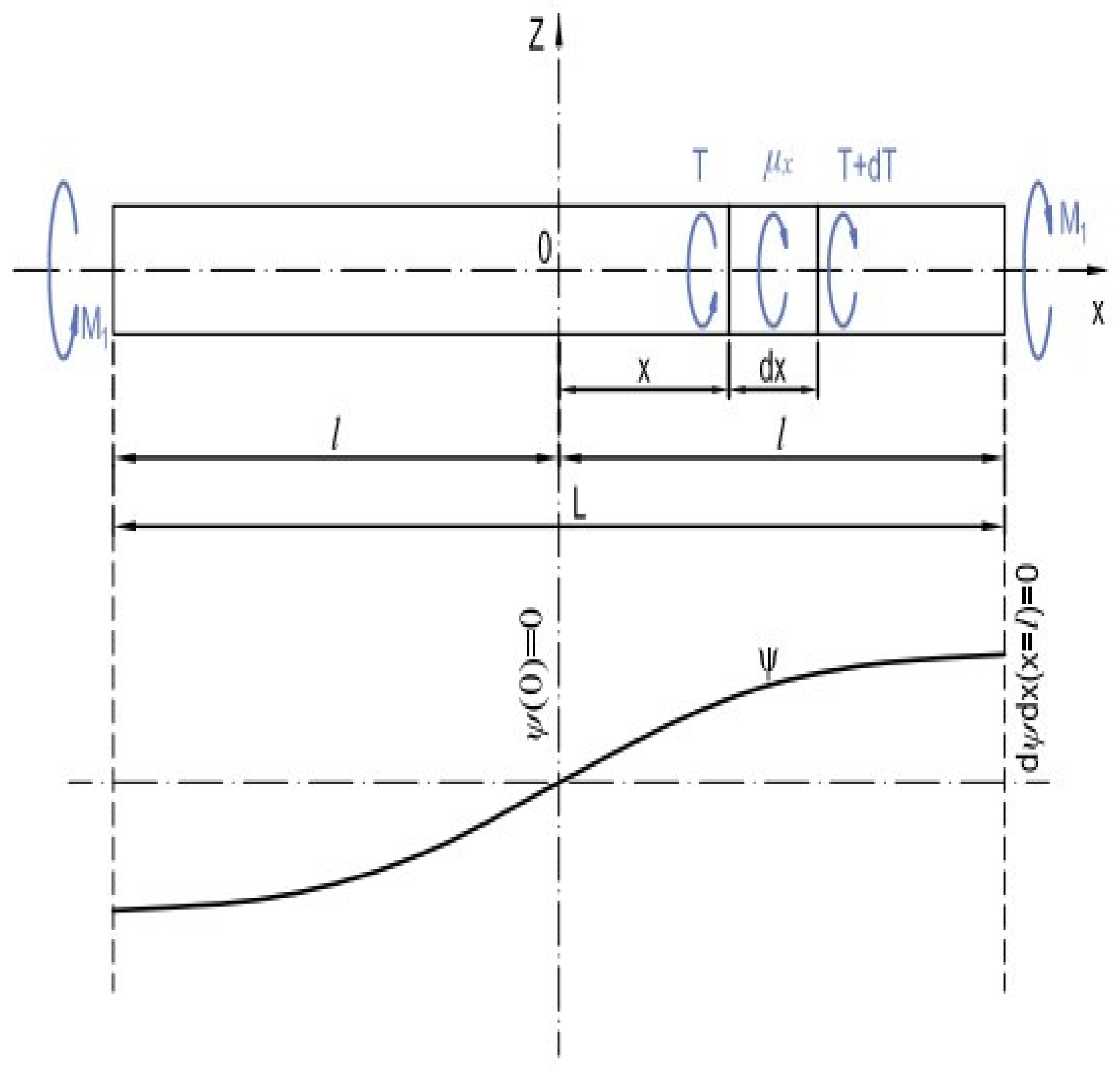
1.1. Classical Beam Theory

Classical beam theory is a simple approach for evaluating the strength of a ship’s hull girder. However, it treats the entire ship as a single beam with equivalent bending stiffness and area, thereby preventing the consideration of local structural component failures.
σ = M z I
Here, M represents the applied bending moment, while I denotes the moment of inertia for one ship section. The vertical distance from the calculation position to the neutral axis is represented by z. Consequently, the deck or ship’s bottom will experience the greatest stress [19].
The direct calculation is based on finite element model analysis, while beam theory relies on three assumptions [20]:
  • The cross-section is infinitely stiff in its own plane.
  • The cross-section remains plain after deformation.
  • The cross-section stays parallel to the bent axis of the beam.

1.2. Theory of Torsion of Thin Wall Prismatic Beam

Thin-walled beams have a unique characteristic that can result in longitudinal deformations known as warping due to torsion. These torsional effects can create significant longitudinal normal stresses called warping stresses. It is important to note that while these stresses are self-balancing, they cannot be classified as localised.
Torsional problems can be divided into two primary types based on the boundary conditions at the beam’s ends: free torsion or Saint-Venant torsion, where the beam can freely warp, and flexural torsion, warping torsion, or warping restrained torsion, where the warping of the ends is either wholly or partially restricted [21].
The torsional moment, T, combines Saint-Venant’s torsional moment, Tt, and the warping torsional moment, Tw.
T = T t + T w
Sectional torque, T, and the distributed external torsional load, x, are in equilibrium and produce [22]
d T = μ x d x
According to the theory of thin-walled girders, the sectional torque consists of a pure torsional component plus a warping contribution [22].
T = T t + T w = G I t   d ψ d x E I w d 3 ψ d x 3
where
E, G—Young’s modulus and shear modulus.
It—Torsional constant.
Iw—Sectorial moment of inertia.
ψ—Twist angle.
Substitution of Equation (3) into (4) leads to the ordinary differential equation of the fourth order.
E I w d 4 ψ d x 4 G I t d 2 ψ d x 2 = μ x
Its solution reads:
ψ = A 0 + A 1 x + A 2 c h β x + A 3 s h β x + ψ p
where
β = G I t E I w
and Ai is the integration constant, while ψp represents a particular solution that depends on μx.
Let us consider the girder’s twisting phenomenon depicted in Figure 2. The girder is subjected to a torsional torque Mt at its ends when μx is 0. It is important to note that the extremities of the girders are constrained against warping. Given the antisymmetric nature of the twist angle in this scenario, i.e., A0 = A2 = 0, fulfilling boundary conditions leads to the computation of the ultimate constants A1 and A3 [22].
x = l :                   T = M t ,       u = d ψ d x u ¯ = 0
The relative sectional warping brought on by the unit beam deformation is denoted by the symbol u ¯ , and the warping function (axial displacement) is denoted by the symbol u. The final expression used to describe the twist angle is:
ψ = M t l G I t x l s h β x β l . c h β l
Now, it is possible to determine sectional forces, i.e., pure torsional and warping torques
T t = M t 1 c h β x c h β l ,             T w = M t c h β x c h β l
and warping (sectorial) bi-moment
B w = E I w d 2 ψ d x 2 = M t s h β x β c h β l
Furthermore, the warping Function (8) takes the form of
u = M t G I t 1 c h β x c h β l u ¯
The thin wall girder theory is based on the following assumptions [23]:
(1)
In its plane, the cross-section’s shape and all of its geometrical dimensions remain unchanged.
(2)
Transverse stresses across the cross-section of the beam are constant.
(3)
At any point along the beam wall, the ratio of wall thickness to the curvature radius is very close to unity.

2. Analysed Ship within the Study

This study focuses on a multipurpose cargo ship currently in operation. The ship features a bulbous bow, a transom, and a single-screw diesel engine constructed as a double-skinned box. This multipurpose cargo ship excels at transporting various types of cargo, including oversized freight, regular cargo, containers, and bulk grain. The ship’s general arrangement (GA), illustrated in Figure 3, provides a comprehensive depiction of its layout, encompassing various decks, such as the forecastle deck, forward and aft tween decks, poop deck, boat deck, bridge deck, main deck, and tank top. This detailed plan offers valuable insights into the ship’s spatial organisation, including key features like hatches, cargo holds, fuel oil tanks, engine rooms, and other critical areas. Such information is essential in ship design, construction, and operation, facilitating a thorough understanding of the ship’s configuration and significant locations. The studied ship complies with the BV and NR 467 rules for the Classification of Steel Ships to ensure its structural strength [24]. Table 1 lists the ship’s most important characteristics.

Geometry and Scantling Details

For the construction of this ship, a longitudinal framing system was used. The cargo compartment of the multipurpose cargo ship features twin hull sides that consist of deep tanks. Figure 4 presents the analysed ship’s midship section, which depicts the ship’s double bottom, side shell, and transverse section. The stiffening at the bottom of the structure is made up of vertical plates, also known as floors, which strengthen the bottom. Side stringers and beams made of angles or channels reinforce the sides and decks. The transverse material provides transverse strength and prevents longitudinal buckling. The span-to-thickness ratio is crucial for resisting compressive stresses and preventing local deformation caused by water pressure.

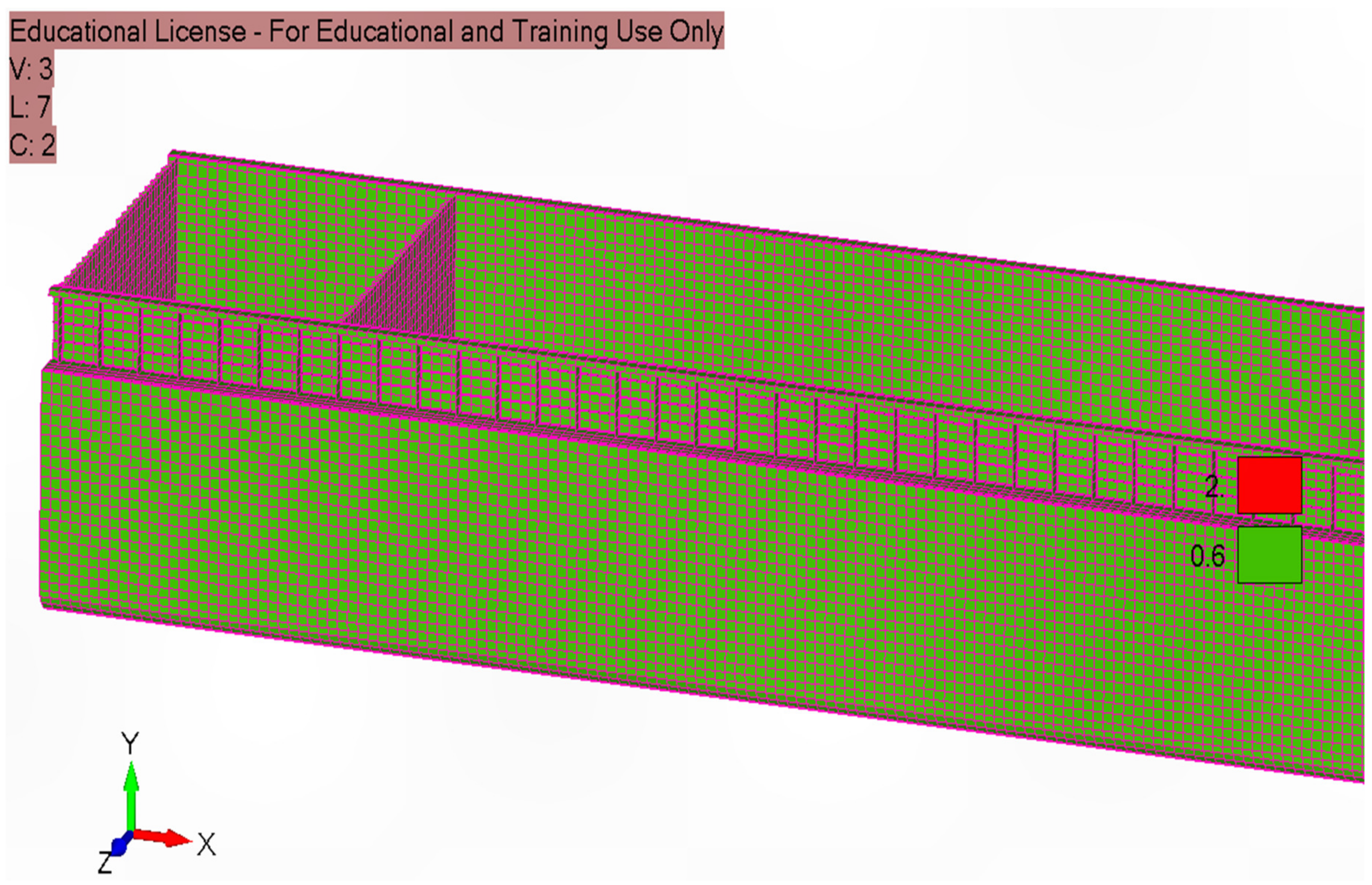
3. Cargo Hold Structural Analysis

The strength of the longitudinal hull girder members, primary supporting members, and transverse bulkheads was evaluated through cargo hold strength analysis.

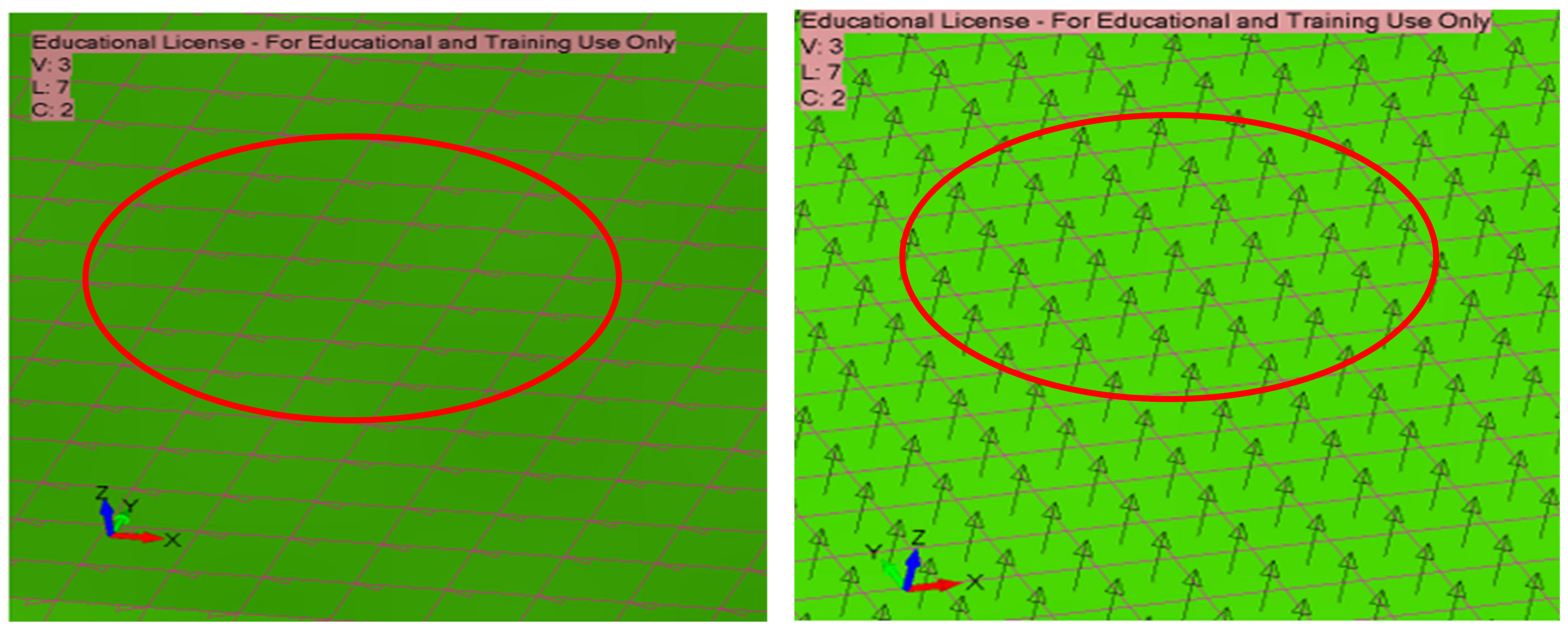
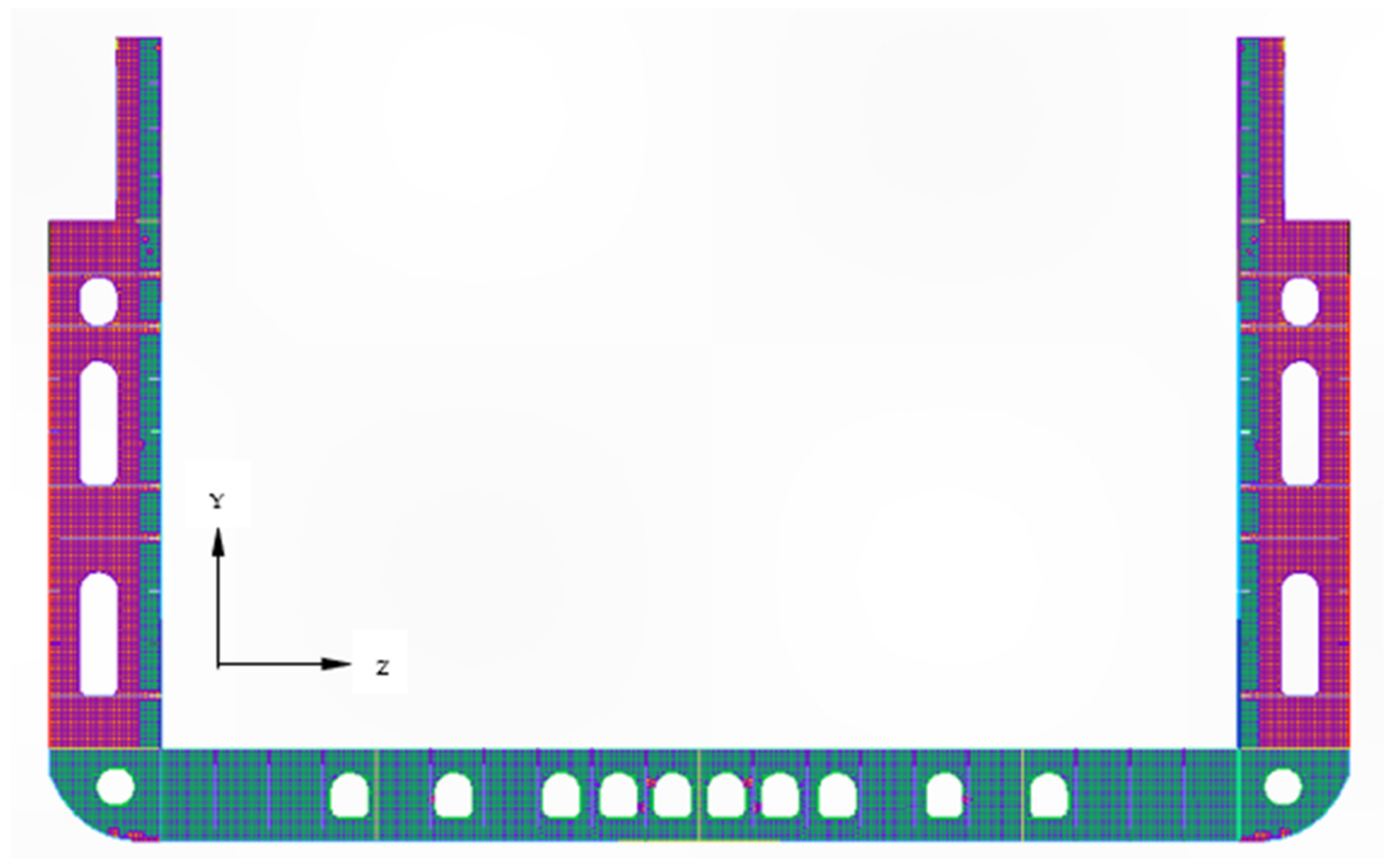
3.1. Coordinate System

In accordance with BV rules NR 467 (Part B, Chapter 1, Section 2), the vessel’s coordinate system is a right-hand coordinate system (as shown in Figure 5) [24]:
Origin: Where the longitudinal plane of symmetry intersects with the aft end of L, and the baseline is where the ship’s intersection is located.
X-axis: Longitudinal axis, positive forwards, along the length of the ship.
Z-axis: Transverse axis, positive towards portside, along the breadth of the ship.
Y-axis: Vertical axis, positive upwards, along the depth/height of the ship.
The coordinate system is illustrated in Figure 5 according to NR 467 rules.

Modelling and Mesh Characteristics

Plate elements were used in the structural modelling to accurately represent the structures. Figure 6 visually demonstrates the crucial convergence achieved between the elements’ first edge and normal vectors, which is essential for obtaining the desired results. Particular attention was given to the dimensions and shapes of these elements, with a preference for quadrilaterals to ensure precision. Triangular elements were only utilised when unavoidable in specific scenarios.
In addition to element types, careful consideration was given to maintaining proper aspect ratios and adhering to linear assumptions in finite element modelling (FE), as depicted in Figure 7. Compliance with recommendations provided by Bureau Veritas (BV) standards (NR 467, Part B, Chapter 5, Appendix 1, and Section 3.4.1) is of paramount importance. The following guidelines provide a framework for ensuring the FE models are accurate and reliable [24].
  • The quadrilateral elements must have an aspect ratio of no more than 4.
  • The angles of the quadrilateral elements must be between 60 degrees and 120 degrees.
  • The angles of the triangle elements must be between 30 degrees and 120 degrees.

3.2. Structural Model

There are four primary steps to creating a finite element model:
  • Geometry creation;
  • Application of meshing and boundary conditions;
  • Solution; and
  • Examination of the findings.
A detailed model of three distinct cargo holds was created for a comprehensive finite element analysis of the ship’s longitudinal strength. To obtain more accurate results, the cargo hold model was developed with a relatively fine mesh using a quadrilateral orthotropic shell element, each with four nodes and six degrees of freedom, including translations in the x, y, and z directions and rotations about the axes. Generally, a coarse mesh model is typically used to verify the global stress levels of longitudinally effective plates [14]. Figure 8 shows a typical mesh arrangement of the transverse web, while Figure 9 displays a detailed cargo hold model.
The properties of the mesh system are as follows:
  • One shell element between each stiffener
  • At least three elements across the depth of girders, floors, web frames, and stringers
  • Eccentric beams are used to represent all stiffeners.
The analysis was conducted using the “Net” thickness method, in which the strength analysis considered the corrosion deductions for the plate and stiffener thickness. The corrosion deductions for plating and stiffening were calculated in accordance with the BV and NR 467 rules for steel ship classification. This method ensures the structural integrity of the cargo ship in both “as-built” and “design life” conditions [24]. The properties of different steel material are shown in Table 2.
Figure 9 shows a detailed representation of the cargo hold model, including various connected parts such as frames and longitudinal stiffeners. This complex structure highlights the strength and effectiveness of the analysis system. Key measurements of the model include an impressively analysed cargo hold length of 72.215 m, a forward hold length of 5.005 m, an aftward hold length of 9.6 m, a width of 15.25 m, and a height of 9.65 m.

3.3. Design Loads

A ship at sea is subjected to various loads that cause structural deformation and stress. The initial step is to assume accurately defined loads acting on the structure to construct a design. The load is gradually transferred from a local structural member to a more significant supporting element [26]. Global or primary loads act on the ship as a beam (hull girder), and primary response loads affect the ship’s structural behaviour. On the other hand, local loads are applied to limited structural models (stiffened panels, single beams, and plate panels). Individual structural components, such as plating panels, ordinary stiffeners, and significant supporting members, are subjected to local loads, which are pressures and stresses applied directly to them [27]. In this analysis, only hull girder loads were applied to investigate this ship’s longitudinal strength.

3.3.1. Hull Girder Loads

There are static and dynamic components to ship hull girder loads, and still water bending moments and shear forces are the most important of these components. The ship’s hull girder can be considered a non-uniform beam subjected to variable loads along its length [28].

Still Water Bending Moments (SWBMs)

Under one load condition, the still water bending moment at a given section of the ship remains constant but varies from one load condition to the next. Each load condition’s duration is likewise a random variable. According to the above load cases, classification society rules expressly provide formulations for evaluating still water bending moment values. The direct computation can also determine the bending moment of still water [29]. This investigation estimated the still water bending moment using the BV and NR 467 rules to classify steel ships [24].

Vertical Wave Bending Moment (VWBM)

An additional vertical bending moment induced by waves must be considered to evaluate the total bending moment. This component depends on the range of navigation of the ship. In this analysis, the analysed ship’s navigation range was unrestricted. The vertical wave bending moment was also calculated according to BV and NR 467 rules for the classification of steel ships [24].

Horizontal Wave Bending Moment (HWBM)

A horizontal wave bending moment occurs when a ship is in a beam and oblique sea [30]. According to the BV and NR 467 rules for the classification of steel ships, the horizontal wave bending moment at any hull transverse section must be calculated [24].
Figure 10 compares the ship’s bending moments, illustrating the distribution and variation of bending moments along the ship’s length (L). This graph provides insights into how environmental factors influence the ship’s structural integrity. It facilitates a better understanding of the ship’s load-bearing capacity and offers valuable information for optimising design and operational decisions to enhance performance and safety.

Wave—Induced Torsional Moment

The wave-induced torsional moment occurs in oblique seas [31]. The wave-induced torsional moment at any transverse hull section is calculated using BV and NR 467 rules (Pt B, Ch. 5, Sec 4) for steel ship classification [24].
Figure 11 and Figure 12 show that the horizontal shear force, bi-moment, and torque attained their maximum levels near the edges at the cargo holds aft bulkhead and forward bulkhead. Despite this, the maximum value was utilised and uniformly applied throughout the entire cargo hold length in this analysis.

3.3.2. Load Cases

When considering load cases for self-propelled multi-purpose cargo ships, it is crucial to account for still water and wave loads. These loads are chosen to identify the most significant effects that can impact the ship’s structural integrity [14]. According to BV, NR 467 regulations for the classification of steel ships [24], load cases can be divided into two categories:
  • Upright ship condition.
In this condition, hull girder loads consist of still water bending and vertical wave bending moments.
2.
Inclined ship condition.
When the ship is inclined, it experiences various hull girder loads, including a still water bending moment, a vertical wave bending moment, a horizontal wave bending moment, and a wave-induced torsional moment.

3.4. Global Strength Analysis

The global strength analysis helps determine the stress and stiffness of a hull girder for specific load cases caused by loading conditions. Its goal is to assess the strength of the hull girder in a longitudinal direction rather than the local strength of local loads. When simple beam theory is insufficient for estimating the structural response of the hull girder, a global strength analysis may be required. Examples include the following:
  • Container ships have substantial deck openings that are susceptible to overall torsional deformation and stress responses.
  • Some types of ships, such as Ro-Ro ships and vehicle carriers, do not have transverse bulkheads running along the length of the ship, or they may have limited bulkheads.
  • On large passenger ships, there may be a partially functional superstructure or top hull girder [29].
In this analysis, the hull structural strength of the ship was investigated by FEMAP integrated with NX-NASTRAN.

3.4.1. Checking Criteria

A strength check was performed with FEMAP, utilising checking criteria from BV and NR 467 rules to classify steel ships [24].
The master allowable stress, σMaster, in N/mm2, was obtained from the following formula:
σ M a s t e r = R y γ R γ M
where Ry is the yielding stress, γR is the resistance partial safety factor, and γM is the material partial safety factor.
For mild steel (Grade A), the master allowable hull girder longitudinal stress, σMASTER, is calculated as 219.42 N/mm2. The maximum allowable hull girder longitudinal stress for high-tensile steel (Grade AH-36), is estimated to be 331.77 N/mm2. It is necessary to confirm that the equivalent hull girder longitudinal stress σ is in accordance with the following formula for different types of analyses:
σ σ M a s t e r

3.4.2. Boundary Conditions

If a cantilever beam has a bending moment on one side, the bending moment will be the same in all parts along the beam’s length. The same concept was used in this FE model to explore the longitudinal strength of the hull girder. On one side of the FE model, bending moments were applied, while the other was restricted by fixed constraints. Rigid elements were built beneath the main deck to transfer the load to multiple nodes. A rigid element links the nodes at the free edges of the structure to the other nodes on the same plane, allowing them to function as a single entity. Detail boundary conditions are shown in Table 3. To establish two boundary conditions, two rigid components were utilised:
  • Constraint: A rigid element was applied at the model’s aft with zero degrees of freedom to clamp.
  • Moment: To establish a hogging/sagging condition, a bending moment was applied in the positive y-direction to a rigid element in the fore part of the model [32].
Table 3. Boundary conditions.
Boundary ConditionsTranslations in DirectionsRotation Around Axes
XYZXYZ
The node at the aft endFixedFixedFixedFixedFixedFixed
The node at the fore endFreeFreeFreeFreeFreeFree

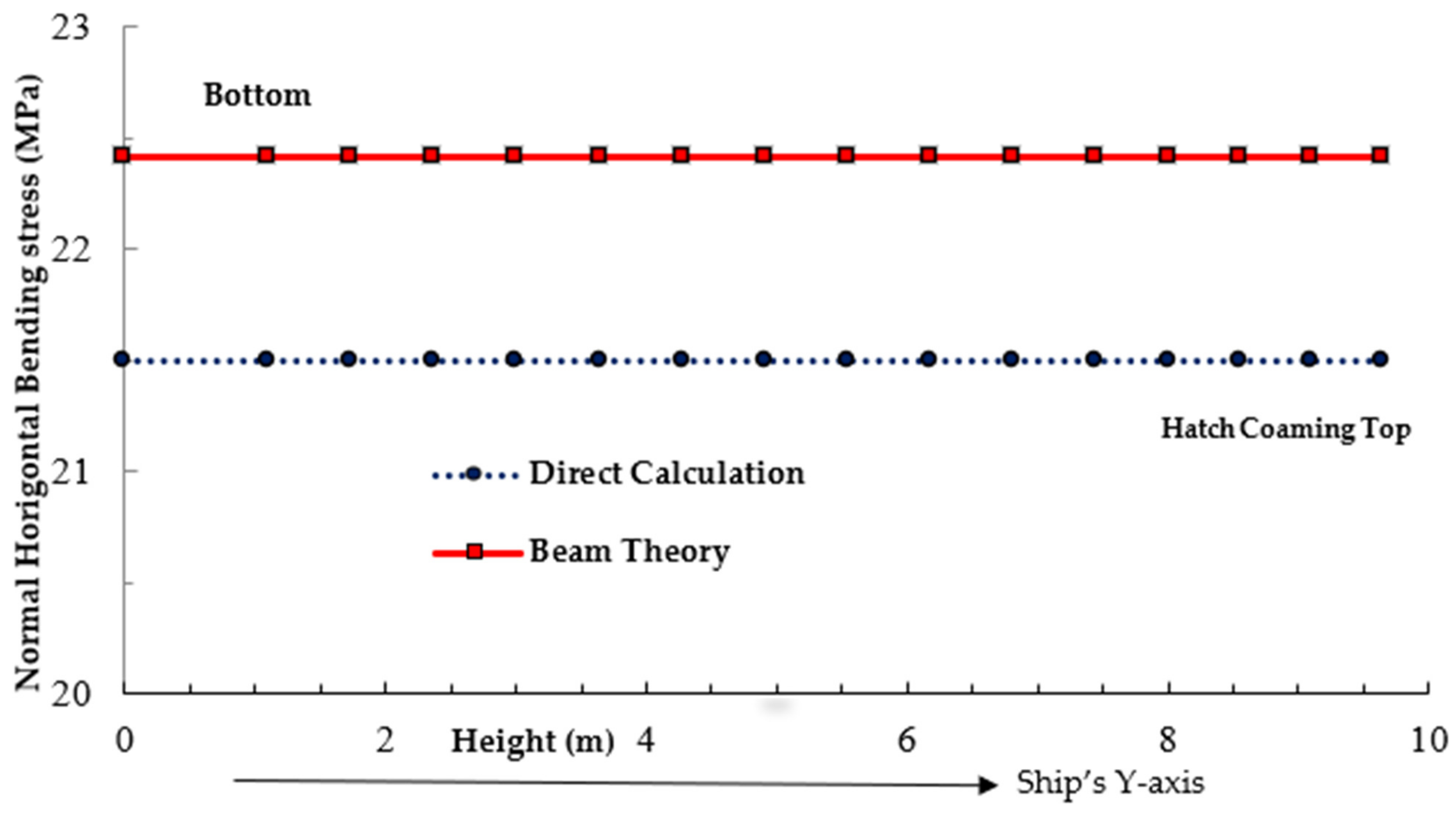
3.4.3. Analysed Ship Structural Analysis—Upright (Head Sea) Condition

Sagging represents the worst-case scenario in this analysis owing to its high hull girder stress in upright conditions (see Figures 14 and 15) and higher bending moment (refer to Table 4). Consequently, the sagging condition was chosen for further investigation in this study. A ship will encounter both still water and vertical wave bending while in an upright position. Analysing stress values in the midship regions is important in evaluating the ship’s structural strength and integrity, as the midship section represents a critical structural parameter and is essential in determining the ship’s capacity to withstand bending stresses.
Validation was conducted by comparing typical stress values obtained from beam theory and direct calculation (Figure 13).
Figure 13 demonstrates a stress difference of approximately 5% between the calculations obtained through beam theory and direct computation. This level of discrepancy is deemed acceptable within the context of beam theory [33].
To satisfy the strength-checking criterion, hull girder normal stress in critical areas had to remain below the maximum allowable stress specified in Section 3.4.1. As illustrated in Figure 14 (hogging—upright condition) and Figure 15 (sagging—upright condition), the top plate of the hatch coaming, made of high-tensile steel, exhibited maximum hull girder normal stress values of 239 MPa and 242 MPa, respectively. These values were well below the permissible stress limit of 331.77 MPa.

3.4.4. Structural Analysis of Ships under Combined Bending and Torsional Loads in Inclined (Oblique Sea) Conditions

When a ship is inclined, it experiences various types of moments, such as still water bending, vertical wave bending, horizontal wave bending, and wave-induced torsional moments. However, this scenario does not fully account for the vertical wave bending moment. According to BV and NR 467 rules for the classification of steel ships, a load combination factor shows the amount of vertical wave bending moment that occurs in an inclined condition. In this situation, the load combination factor for the vertical wave bending moment was 0.4, indicating that only 40% would be effective [24]. Figure 16 shows the results of the hull girder normal stress for an inclined condition.
Figure 16 and Figure 17 show that the hatch coaming top plate had maximum hull girder normal stress values lower than the master allowable stress, as stated in Section 3.4.1. In an inclined state, the still water bending moment, the vertical wave bending moment, the horizontal wave bending moment, and the wave—induced torsional moment are all active. Therefore, it is crucial to ascertain each moment’s contribution to hull girder stresses.

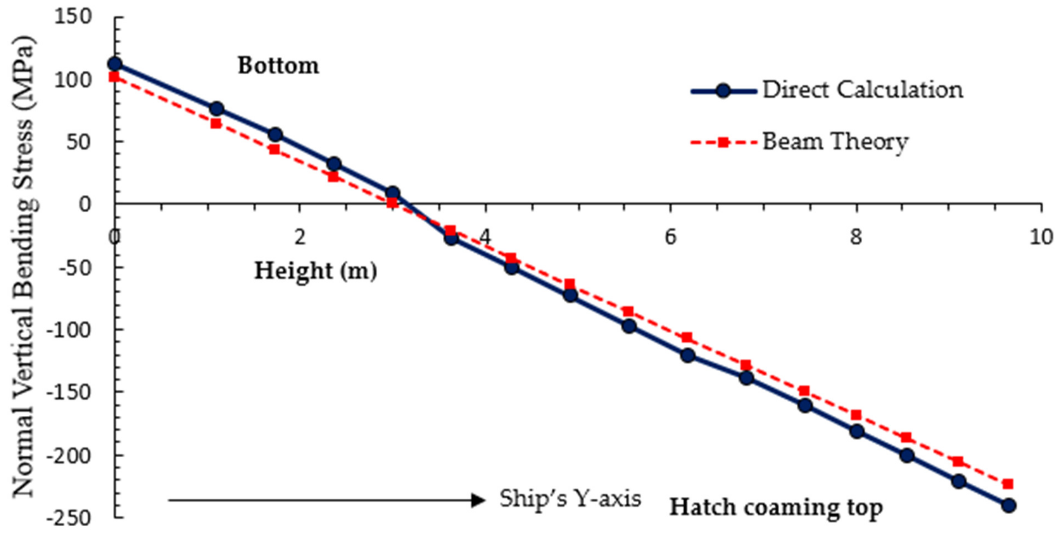
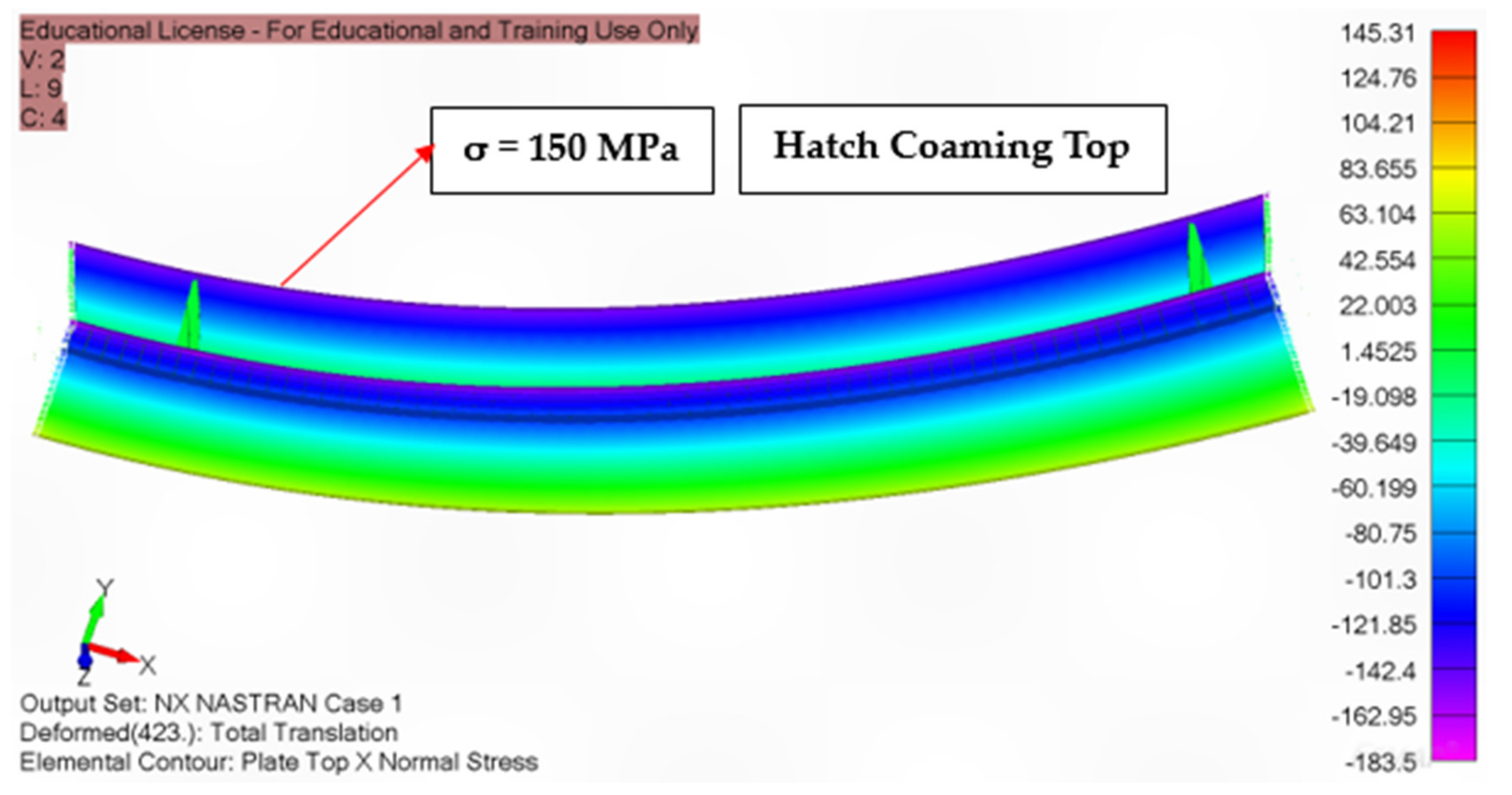
Impact of Still Water and Vertical Wave Bending Moment in an Inclined (Oblique Sea) Condition

Validation (Figure 18) was carried out by comparing hull girder normal stress values obtained from beam theory with those calculated directly.
Figure 18 indicates a stress difference of approximately 5% between the calculations obtained through beam theory and direct computation. This level of discrepancy is considered acceptable within the context of beam theory [33]. Figure 19 shows that the hull girder normal stress due to still water and vertical wave bending moment at midship (sagging—inclined condition) occurs primarily at the hatch coaming top, accounting for approximately 70% of the total stress in inclined condition.

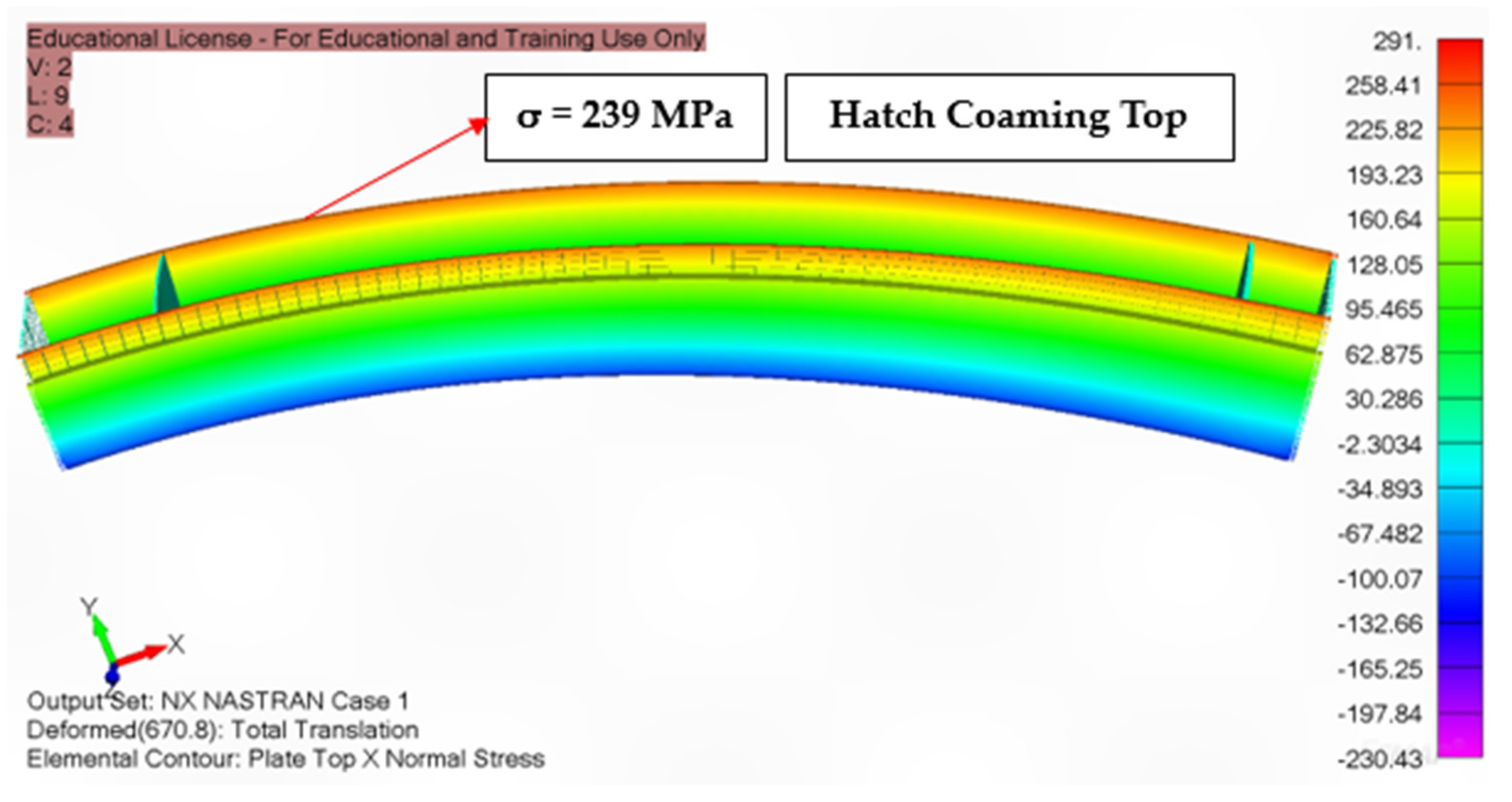
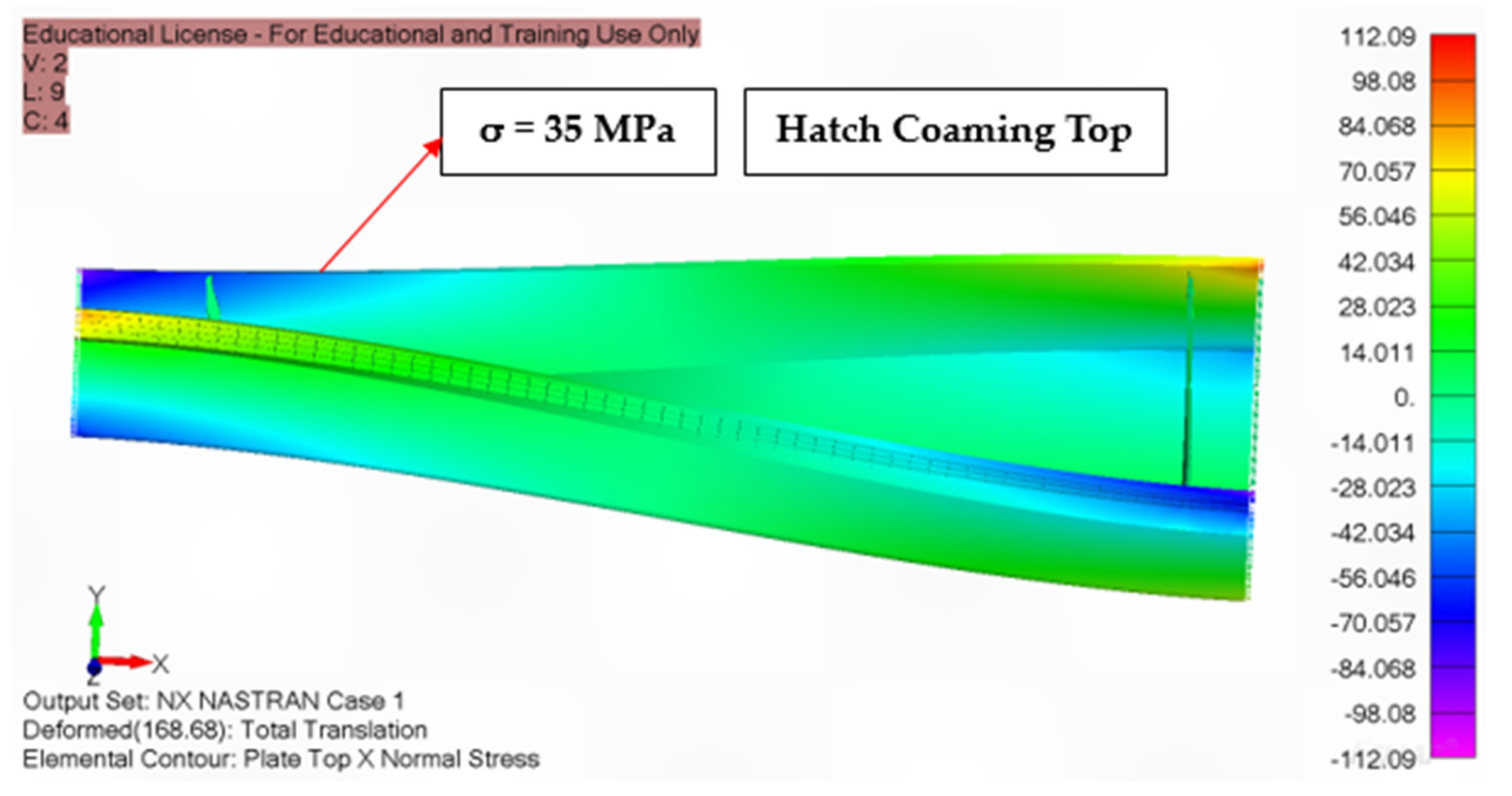
Impact of the Wave—Induced Torsional Moment in an Inclined (Oblique Sea) Condition

For validation, the hull girder warping the normal stress from torsion values obtained from thin-walled girder theory was compared to the direct calculation (Figure 20).
Figure 20 shows a stress difference of approximately 10% between the thin wall girder theory and direct calculation. However, this difference can be considered acceptable based on the thin wall girder theory hypothesis [33]. Figure 21 illustrates that the most significant hull girder warping normal stress, caused by torsion, occurs near the cargo hold bulkheads and at the hatch coaming’s top, accounting for approximately 20% of the total stress in an inclined position.

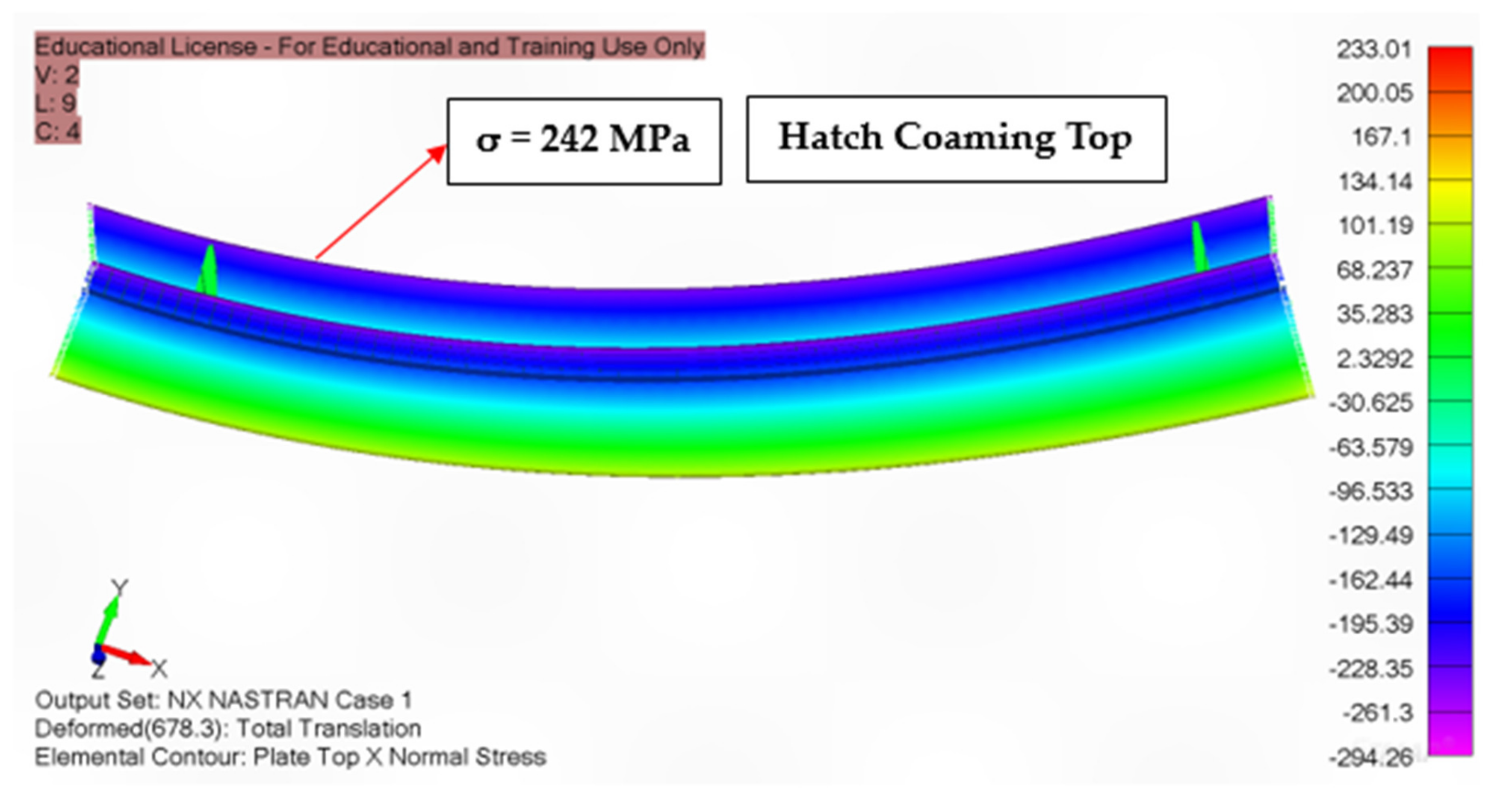
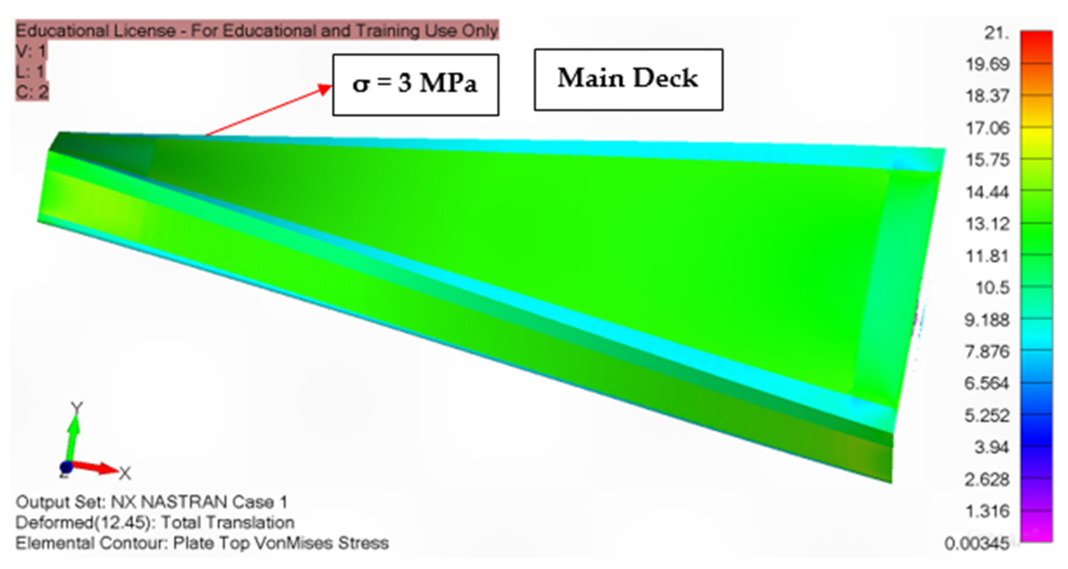
Impact of Horizontal Wave Bending Moment in an Inclined (Oblique Sea) Condition

Validation was conducted by comparing hull girder normal stress values derived from beam theory and direct calculation (Figure 22).
Figure 22 and Figure 23 show that the maximum hull girder normal stress values resulting from the horizontal wave bending moment are equivalent to those of the vertical side plate (hatch coaming plate). These stress levels were below the maximum allowable stress specified in Section 3.4.1 and accounted for approximately 10% of the inclined condition.

3.4.5. Impact of Torsion between the Open—Deck and Closed—Deck Ships

Investigating the impact of torsion on open-deck vessels necessitates comparing open-deck and closed-deck ships concerning torsional loads. A main deck panel spanning from side to side within the open-deck ship under investigation has been introduced to facilitate this comparison. This panel simulates the structure of a closed deck, allowing for an assessment of the torsional behaviour of both open- and closed-deck ships under identical torsional loads. The preceding section has already addressed the influence of torsion on open-deck ships. A thorough examination of the hull girder, warping normal stress resulting from torsion, is conducted to validate the findings. This examination involves direct calculations for both open-deck and closed-deck ships, ensuring a comprehensive understanding of the torsion-related stress levels in each case.
It is vital to know the impact of torsion on both open- and closed-deck ships. Section 3.4.4. covers the effect of torsion on open-deck ships. To verify the hull girder stress caused by torsion, direct calculation values were tested for both open- and closed-deck ships (Figure 24).
Figure 24 and Figure 25 show that hull girder warping normal stresses were considerably less significant in closed-deck ships, whereas they accounted for roughly 20% of hull girder normal stresses in open-deck ships. In open-deck ships, the warping normal stress reaches zero at the shear centre point while registering higher values at the bottom and main deck levels, making these areas more critical regarding warping normal stress considerations.

4. Buckling of Plate Panel and Ordinary Stiffener

The ship’s structural components are subjected to compressive loads, which can cause buckling. This study investigated the impact of axial, bending, and shear loads on the ship’s structural components. The primary factors contributing to plate buckling in ship structural components include [34]:
  • Elevated compressive and residual stresses.
  • Heightened shear stresses.
  • Combined stress conditions.
  • Insufficient flexural rigidity.
  • Inadequate stiffening.
  • Notable initial imperfections.
  • Extensive and improper utilisation of high-tensile steel.
  • Excessive material degradation resulting from general and localised pitting corrosions.
The primary failure mechanisms observed in stiffened panels include:
  • Lateral buckling of stiffeners.
  • Torsional buckling of stiffeners.
  • Flexural buckling of stiffeners.
  • Flexural buckling of the plate-stiffener combination.
  • Buckling of plate panels between stiffeners.
The combined critical stress, denoted as σcomb, is determined for plate panels that experience compressive axial, bending, and shear stress as described in [34]:
F           1     for   σ c o m b F       R e H   2 γ R γ m
F           4 σ c o m b R e H γ R γ m   1 σ c o m b R e H γ R γ m         f o r         σ c o m b F > R e H   2 γ R γ m
where F and ReH are compressive force and upper yield strength, respectively.
The critical buckling stress, σc, for compressive axial and bending loads is defined as [34]:
σ C = σ E         f o r     σ E     R e H 2
σ C = R e H 1 R e H 4 σ E     f o r       σ E   >   R e H 2
where σE is the Euler buckling stress.
The critical buckling stress of ordinary stiffeners is estimated as:
σ C γ R γ m     | σ b |
where σb is axial stress.
Figure 26 illustrates the buckling capacity of the plate panel within the midship section. Boundary condition of buckling analysis is shown in Table 5. When the buckling factor exceeds one, it indicates non-compliance with the buckling criteria defined in the BV rule. This figure highlights the red lines, representing plate panels with a buckling factor exceeding one, signifying a failure to meet the criteria. The regulations established by classification societies are known for their conservative nature. Therefore, the following sensitivity analysis was conducted on this midship section using Femap software 2021.2 to assess whether the failure areas satisfied the buckling criteria.

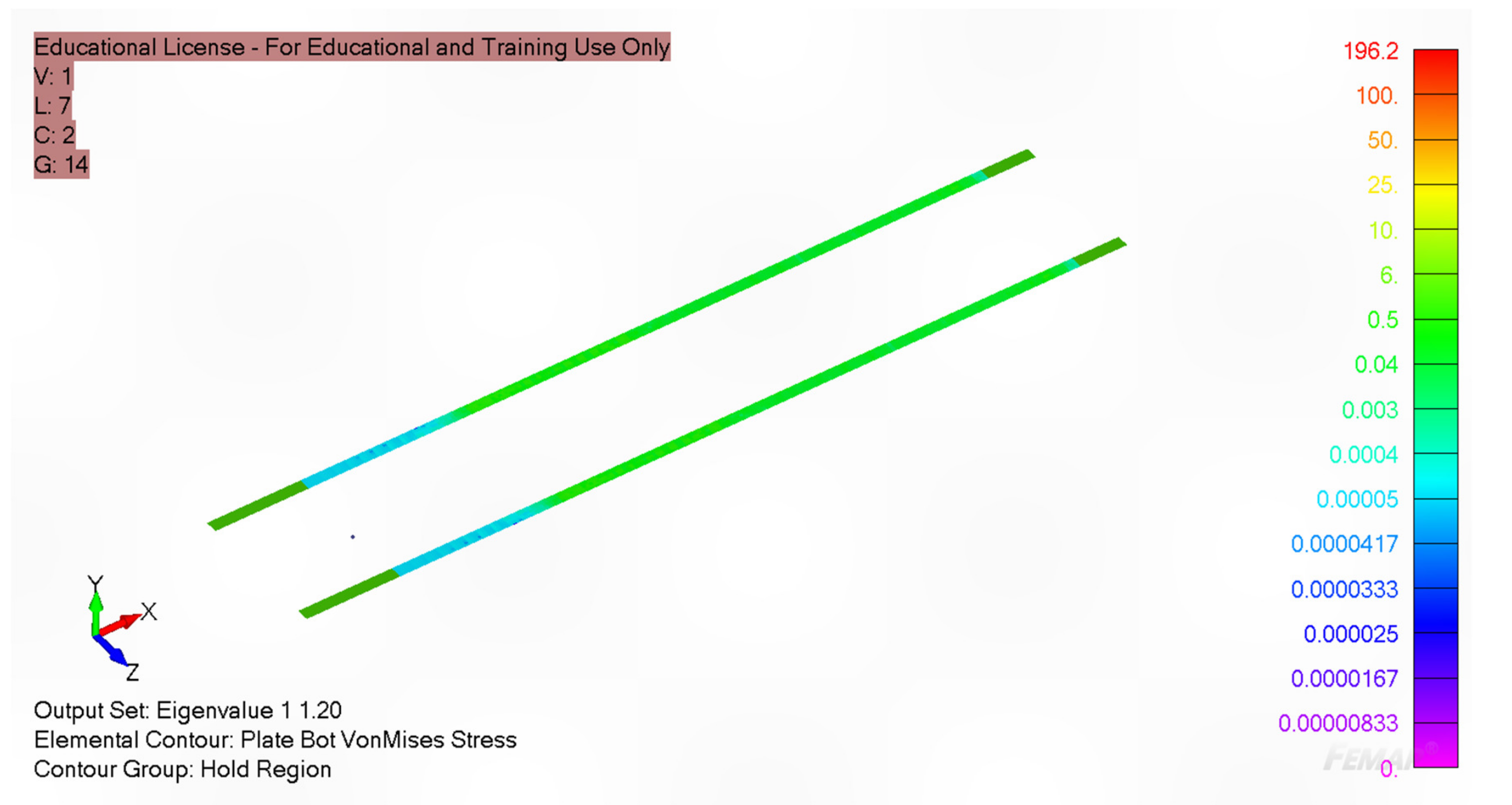
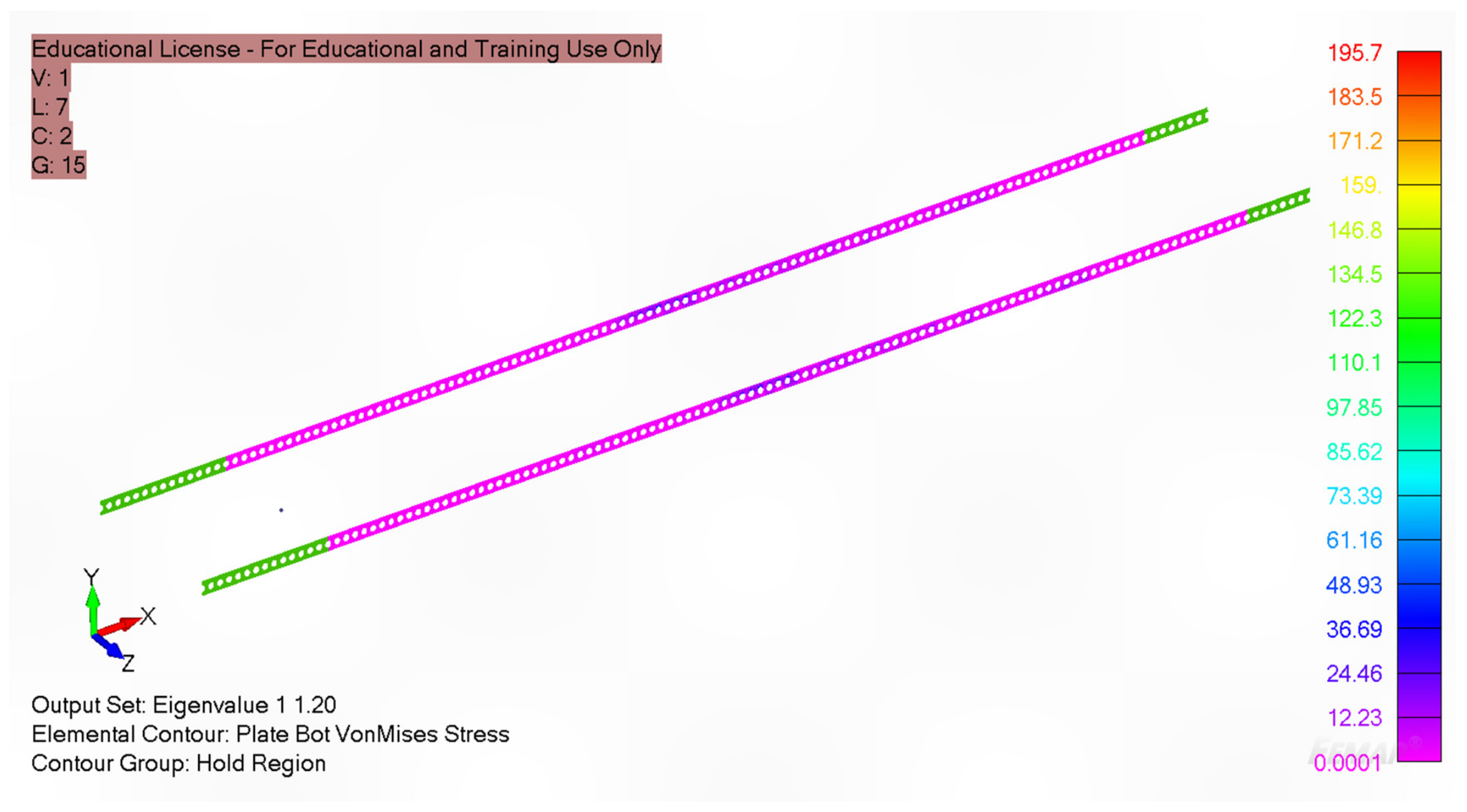
4.1. Buckling of Inner Bottom Panel

Figure 27 examines the inner bottom plate’s buckling under hydrodynamic and inertia loads. The eigenvalue hit 1.20 with a hydrodynamic and inertia load of 204.13 kN/m2 estimated using BV Mars 2000, confirming linear buckling even in this challenging scenario.

4.2. Buckling of Inner Shell Panel

Figure 28 demonstrates the resilience of the inner shell plate under hydrodynamic and inertia loads, calculated analytically at 204.13 kN/m2 by BV Mars 2000. The resulting eigenvalue of 1.20 confirms compliance with linear buckling criteria, even when subjected to hydrodynamic and inertia forces.

5. Discussion

This investigation is grounded on the Euler–Bernoulli beam theory to analyse a ship’s strength under various loading conditions, including still water bending moment, vertical wave bending moment, and horizontal wave bending moment. Additionally, it is based on thin wall girder theory for a ship’s strength calculations concerning wave-induced torsional moments. The hull girder normal stress discrepancy between beam theory and direct calculation was around 5% in both sagging–upright and sagging–inclined conditions. On the other hand, the warping stress difference between the direct calculation and the thin-wall girder theory was about 10%, which remains consistent with the allowances of the thin-wall girder theory.
The strength of the hull girders was examined in this investigation. A relatively fine mesh was used in this analysis to validate the global stress levels of longitudinally effective plates, and it produced sufficient accuracy at a large scale. The upright and inclined load scenarios were examined in this analysis. In addition to the upright load condition, the inclined load condition is vital for open-deck ships because open-deck ships are subject to substantially higher hull girder warping normal stress in inclined conditions than closed-deck ships, which can significantly impact the structural integrity of the ship, particularly in the cargo hold end regions, where the highest hull girder warping normal stresses are often experienced.
The buckling analysis of the midship section using BV Mars 2000 software found that the buckling criteria for the inner side shell panel and inner bottom plan in the bilge area did not meet the required standards. This is because classification societies’ rules tend to be conservative. However, after conducting a sensitivity analysis of buckling using Femap software 2021.2, it was revealed that the eigenvalue exceeds one, confirming the occurrence of linear buckling even in this challenging scenario.
Maximum torsional stiffness is required for ships to minimise vibration and maintain stability. A ship’s design parameters can be optimised using the model generated and provided in this research. As this research progresses, work will focus on optimising multiple objectives (weight and production costs) and identifying the significant ship structural members that substantially impact the overall strength of ship structures. It is vital to reduce the steel weight of ships to save on manufacturing costs while maintaining standard safety criteria.
Literature reviews of pertinent previous works have been incorporated to better position the findings within the broader landscape of ship structural engineering research. For instance, Jurišić et al. [35] previously emphasised the significant impact of understanding still water and wave load effects on midship structural integrity, aligning with the current findings. Furthermore, the approach of emphasising the importance of conducting buckling analyses to evaluate structural integrity resonates with the work of H. Sun and X. Wang [36]. These findings are placed in the context of previous works to demonstrate their relevance and contribution to improving ship structures’ safety and reliability.

6. Conclusions

This investigation conducted a comprehensive analysis of a detailed cargo hold model to evaluate the longitudinal strength of the hull girder structural members. The linear longitudinal strength of the ship was assessed using a 3D finite element model of the three distinct cargo holds. The hull girder stress values were validated by comparing the results against those obtained from Euler–Bernoulli beam theory and direct calculations. Additionally, the validity of torsional stress was confirmed by comparing the results with thin wall girder theory and direct calculation outcomes. The study examined the impact of various loading scenarios on the structural response, comparing the effect of torsion between closed-deck and open-deck ships. Finally, a buckling analysis was performed to assess the ship’s buckling criteria, which were confirmed to be met as the eigenvalue exceeded one.
The structural investigation of the ship under consideration reveals the following:
  • Hull girder stresses at midship due to still water bending and vertical wave bending moments contribute to approximately 70% of the total stress in an inclined condition.
  • Hull girder torsion stress is highest near cargo hold bulkheads. Torsion induces the most typical warping stress near the top of the hatch coaming, constituting approximately 20% of the total stress in inclined conditions.
  • In an inclined position, the maximum typical stress values from the horizontal wave bending moment are equivalent to those of the vertical side plate (hatch coaming plate) and contribute roughly 10%.
  • In closed-deck ships, hull girder warping normal stress is considerably less significant, accounting for around 20% of the total stress in open-deck ships.
This analysis focused on examining the linear longitudinal strength of a hull girder. Further analysis will be conducted to assess the ultimate strength of the hull girder and the ship’s structural integrity.

Author Contributions

Conceptualization, J.A., F.F. and S.M.I.M.; methodology, J.A., F.F. and S.M.I.M.; software, J.A.; validation, J.A. and F.F.; formal analysis, J.A. and S.M.I.M.; resources, J.A. and S.M.I.M.; writing—original draft preparation, J.A.; writing—review and editing, J.A., F.F. and S.M.I.M.; supervision, F.F.; project administration, J.A. and F.F. All authors have read and agreed to the published version of the manuscript.

Funding

This research received no external funding.

Institutional Review Board Statement

Not applicable.

Informed Consent Statement

Not applicable.

Data Availability Statement

The article includes the data supporting the findings and can be obtained from the corresponding authors upon request.

Acknowledgments

First and foremost, I would like to thank and convey my gratitude to Francis Franklin, my supervisor and co-author on this work, who always comes forward to assist me whenever I ask for advice on my research. Additionally, I would like to thank Bureau Veritas and Siemens Digital Industries Software for permitting me to use their software, BV Mars 2000 and Femap/Nastran, respectively.

Conflicts of Interest

The authors affirm that they do not have any known competing financial interests or personal relationships that might have influenced the work presented in this paper.

References

  1. Yao, T. Hull girder strength. Mar. Struct. 2003, 16, 1–13. [Google Scholar] [CrossRef]
  2. Novikov, V.V.; Antonenko, S.V.; German, A.P.; Kitaev, M.V. Effect of Ship Torsion with Wide Hatches on the Hull’s Stress State. In Proceedings of the Twenty-Fifth International Ocean and Polar Engineering Conference, Kona, HI, USA, 21–26 June 2015; OnePetro: Richardson, TX, USA, 2015. [Google Scholar]
  3. Shama, M. Torsion and Shear Stresses in Ships; Springer Science & Business Media: Berlin/Heidelberg, Germany, 2010. [Google Scholar]
  4. Elbatouti, A.; Liu, D.; Jan, H. Structural Analysis of Sl-7 Containership under Combined Loading of Vertical, Lateral and Torsional Moments Using Finite Element Techniques (SL-7-3); 1974. Available online: http://www.shipstructure.org/ (accessed on 11 November 2022).
  5. Ostapenko, A.; Chu, P.-C. Torsional Strength of Longitudinals in Marine Structures; Lehigh University, Department of Civil Engineering: Bethlehem, PA, USA, 1986. [Google Scholar]
  6. Jurišić, P.; Parunov, J. Structural aspects during conversion from general cargo ships to cement carriers. Brodogr. Teor. I Praksa Brodogr. I Pomor. Teh. 2021, 72, 37–55. [Google Scholar] [CrossRef]
  7. Vernon, T.A.; Nadeau, Y. Thin-Walled Beam Theories and Their Applications in the Torsional Strength Analysis of Ship Hulls; Defence Research Establishment Atlantic Dartmouth: Dartmouth, NS, USA, 1987. [Google Scholar]
  8. Tang, H.; Ren, H.; Zhong, Q. Design and model test of structural monitoring and assessment system for trimaran. Brodogr. Teor. I Praksa Brodogr. I Pomor. Teh. 2019, 70, 111–134. [Google Scholar] [CrossRef]
  9. Valsgard, S.; Svensen, T.E.; Thorkildsen, H. A computational method for analysis of container vessels. In Proceedings of the 6th international Symposium on Practical Design of Ships and Mobile Units, PRADS 95, Seoul, Republic of Korea, 17–22 September 1995. [Google Scholar]
  10. Paik, J.K.; Thayamballi, A.K.; Pedersen, P.T.; Park, Y.I. Ultimate strength of ship hulls under torsion. Ocean. Eng. 2001, 28, 1097–1133. [Google Scholar] [CrossRef]
  11. Iijima, K.; Shigemi, T.; Miyake, R.; Kumano, A. A practical method for torsional strength assessment of container ship structures. Mar. Struct. 2004, 17, 355–384. [Google Scholar] [CrossRef]
  12. Senjanović, I.; Tomašević, S.; Rudan, S.; Senjanović, T. Role of transverse bulkheads in hull stiffness of large container ships. Eng. Struct. 2008, 30, 2492–2509. [Google Scholar] [CrossRef]
  13. Chirică, R.; MUŞAT, S.D.; Boazu, D.; Beznea, E.-F. Torsional Analysis of Ship Hull Model. In Proceedings of the International Conference on Diagnosis and Prediction in Mechanical Engineering Systems (DIPRE’09), Galati, Romania, 22–23 October 2009. [Google Scholar]
  14. Parunov, J.; Uroda, T.; Senjanović, I. Structural analysis of a general cargo ship. Brodogr. Teor. I Praksa Brodogr. I Pomor. Teh. 2010, 61, 28–33. [Google Scholar]
  15. Senjanović, I.; Vladimir, N.; Tomić, M. Investigation of torsion, warping and distortion of large container ships. Ocean. Syst. Eng. 2011, 1, 73–93. [Google Scholar] [CrossRef]
  16. Rörup, J.; Maciolowski, B.; Darie, I. FE-based strength analysis of ship structures for a more advanced class approval. In Proceedings of the PRADS2016, Copenhagen, Denmark, 4–8 September 2016. [Google Scholar]
  17. Vladimir, N.; Senjanović, I.; Malenica, Š.; De Lauzon, J.; Im, H.; Choi, B.-K.; Seung Cho, D. Structural design of ultra large ships based on direct calculation approach. Pomor. Zb. 2016, 1, 63–79. [Google Scholar] [CrossRef]
  18. Senjanović, I.; Vladimir, N.; Malenica, S.i.; Tomić, M. Improvements of beam structural modelling in hydroelasticity of ultra large container ships. In Proceedings of the International Conference on Offshore Mechanics and Arctic Engineering, Rotterdam, The Netherlands, 19–24 June 2011; pp. 219–228. [Google Scholar]
  19. Mao, F. Longitudinal Ultimate Bending Strength Analysis of Ship Structure For Emergency Response; Delft University of Technology: Delft, The Netherlands, 2015. [Google Scholar]
  20. Bauchau, O.A.; Craig, J.I. Euler-Bernoulli beam theory. In Structural Analysis; Springer: Dordrecht, The Netherlands, 2009; pp. 173–221. [Google Scholar]
  21. Hossain, M. A Beam Model for the Structures of Ship Hull Girder; UNSW Sydney: Sydney, NSW, Australia, 1997. [Google Scholar]
  22. Senjanović, I.; Senjanović, T.; Tomašević, S.; Rudan, S. Contribution of transverse bulkheads to hull stiffness of large container ships. Brodogr. Teor. I Praksa Brodogr. I Pomor. Teh. 2008, 59, 228–238. [Google Scholar]
  23. Librescu, L.; Song, O. Thin-Walled Composite Beams: Theory and Application; Springer Science & Business Media: Berlin/Heidelberg, Germany, 2005; Volume 131. [Google Scholar]
  24. Veritas, B. NR 467 Rules for the Classification of Steel Ships. Paris, France, 2018. Available online: https://marine-offshore.bureauveritas.com/nr467-rules-classification-steel-ships (accessed on 11 November 2022).
  25. Huang, L.; Li, B.; Wang, Y. FEM and EFG Quasi-Static Explicit Buckling Analysis for Thin-Walled Members. Open J. Civ. Eng. 2017, 7, 432–452. [Google Scholar] [CrossRef]
  26. Okumoto, Y.; Takeda, Y.; Mano, M.; Okada, T. Design of Ship Hull Structures: A Practical Guide for Engineers; Springer Science & Business Media: Berlin/Heidelberg, Germany, 2009. [Google Scholar]
  27. Rigo, P.; Rizzuto, E. Analysis and design of ship structure. Ship Des. Constr. 2003, 1, 1–18. [Google Scholar]
  28. Shama, M. Buckling of Ship Structures; Springer Science & Business Media: Berlin/Heidelberg, Germany, 2012. [Google Scholar]
  29. Wang, X.; Moan, T. Stochastic and deterministic combinations of still water and wave bending moments in ships. Mar. Struct. 1996, 9, 787–810. [Google Scholar] [CrossRef]
  30. Chen, Z.; Gui, H.; Dong, P.; Yu, C. Numerical and experimental analysis of hydroelastic responses of a high-speed trimaran in oblique irregular waves. Int. J. Nav. Archit. Ocean. Eng. 2019, 11, 409–421. [Google Scholar] [CrossRef]
  31. Rörup, J.; Darie, I.; Maciolowski, B. Strength analysis of ship structures with open decks. Ships Offshore Struct. 2017, 12, S189–S199. [Google Scholar] [CrossRef]
  32. Ahmed, F. Development of Guidelines Allowing to Predict the Contribution of the Superstructure to the Hull Girder Strength. Master’s Thesis, University of Liège, Liège, Belgium, 2017. [Google Scholar]
  33. Brassey, C.A.; Margetts, L.; Kitchener, A.C.; Withers, P.J.; Manning, P.L.; Sellers, W.I. Finite element modelling versus classic beam theory: Comparing methods for stress estimation in a morphologically diverse sample of vertebrate long bones. J. R. Soc. Interface 2013, 10, 20120823. [Google Scholar] [CrossRef] [PubMed]
  34. Pereira, T.; Garbatov, Y. Multi-attribute decision-making ship structural design. J. Mar. Sci. Eng. 2022, 10, 1046. [Google Scholar] [CrossRef]
  35. Jurišić, P.; Parunov, J.; Garbatov, Y. Aging effects on ship structural integrity. Brodogr. Teor. I Praksa Brodogr. I Pomor. Teh. 2017, 68, 15–28. [Google Scholar] [CrossRef]
  36. Sun, H.; Wang, X. Buckling and ultimate strength assessment of FPSO structures. In Proceedings of the SNAME Maritime Convention, Houston, TX, USA, 19–21 October 2005; p. D021S003R004. [Google Scholar]
Figure 1. A ship travelling through oblique waves [3].
Jmse 12 00059 g001
Figure 2. Beam subjected to torsion [22].
Jmse 12 00059 g002
Figure 3. General arrangement plan of the analysed ship.
Jmse 12 00059 g003
Figure 4. Midship section of the analysed ship.
Jmse 12 00059 g004
Figure 5. Coordinate system for modelling in FEMAP.
Jmse 12 00059 g005
Figure 6. Harmonised first edge (left) and normal vectors (right) in FEMAP.
Jmse 12 00059 g006
Figure 7. Mesh shapes in FEMAP.
Jmse 12 00059 g007
Figure 8. A typical mesh arrangement of the transverse web in FEMAP.
Jmse 12 00059 g008
Figure 9. Generated FE model of the analysed ship in FEMAP.
Jmse 12 00059 g009
Figure 10. Comparison of the analysed ship’s bending moments along the ship’s length (L).
Jmse 12 00059 g010
Figure 11. Wave—induced torsional moment of the analysed ship along the ship’s length (L) (wave at 60°).
Jmse 12 00059 g011
Figure 12. Wave—induced torsional moment of the analysed ship along the ship’s length (L) (wave at 120°).
Jmse 12 00059 g012
Figure 13. Comparison of hull girder normal stress between beam theory and direct calculation at midship (sagging—upright condition) along the depth (height) of the ship.
Jmse 12 00059 g013
Figure 14. Hull girder normal stress at midship (hogging—upright condition).
Jmse 12 00059 g014
Figure 15. Hull girder normal stress at midship (sagging—upright condition).
Jmse 12 00059 g015
Figure 16. Hull girder normal stress at midship due to combined bending and torsional load (sagging—inclined condition) along the depth (height) of the ship.
Jmse 12 00059 g016
Figure 17. Hull girder normal stress at midship due to combined bending and torsional load (Sagging—Inclined condition).
Jmse 12 00059 g017
Figure 18. Comparison of hull girder stress between beam theory and direct calculation at midship due to still water and vertical wave bending moment (sagging—inclined condition) along the depth (height) of the ship.
Jmse 12 00059 g018
Figure 19. Hull girder normal stress at midship due to still water and vertical wave bending moment (sagging—inclined condition).
Jmse 12 00059 g019
Figure 20. Comparison of hull girder warping normal stress due to torsion between thin wall girder theory and direct calculation (along with vertical side plate; sagging—inclined condition) along the depth (height) of the ship.
Jmse 12 00059 g020
Figure 21. Maximum hull girder warping normal stress due to torsion (sagging—inclined condition).
Jmse 12 00059 g021
Figure 22. Maximum hull girder normal stress due to horizontal wave bending moment (sagging—inclined condition) along the depth (height) of the ship.
Jmse 12 00059 g022
Figure 23. Maximum hull girder stress due to horizontal wave bending moment (sagging—inclined condition).
Jmse 12 00059 g023
Figure 24. Comparison of hull girder warping normal stress between open— and closed—deck ships along the depth (height) of the ship.
Jmse 12 00059 g024
Figure 25. The hull girder warping normal stress due to torsion (closed—deck ship).
Jmse 12 00059 g025
Figure 26. Buckling of plate panel in BV Mars, 2000.
Jmse 12 00059 g026
Figure 27. Inner Bottom Plate Panel Buckling under Hydrodynamic and Inertia Loads in Femap.
Jmse 12 00059 g027
Figure 28. Inner Shell Plate Panel Buckling under Hydrodynamic and Inertia Loads in Femap.
Jmse 12 00059 g028
Table 1. Main parameters of the ship.
ItemsDimensions
Length overall104.135 m
Length between perpendicular98.535 m
Breadth moulded15.25 m
Depth7.45 m
Design Draught4.90 m
Scantling Draught5.60 m
Range of navigationUnrestricted
Loading sequence2R (2 Runs)
PropulsionSelf-propelled
Service Speed12 knots
Table 2. Material properties of steel [25].
PropertiesSymbolsValues
Elasticity modulusE206 GPa
Densityρ7850 kg/m3
Poisson’s ratioν0.30
Yield Stress Re235 (for MS)
355 (for HTS)
Table 4. Hull girder strength criteria.
ItemsHogging (kNm)Sagging (kNm)
Design still water bending moment125,651−113,909
Design vertical wave bending moment177,581−192,769
Table 5. Boundary Conditions.
Boundary ConditionsTranslations in DirectionsRotation Around Axes
XYZXYZ
The node at the aft endFixedFixedFixedFixedFixedFixed
The node at the fore endFixedFixedFixedFreeFreeFree
Disclaimer/Publisher’s Note: The statements, opinions and data contained in all publications are solely those of the individual author(s) and contributor(s) and not of MDPI and/or the editor(s). MDPI and/or the editor(s) disclaim responsibility for any injury to people or property resulting from any ideas, methods, instructions or products referred to in the content.

