Article

Bearing Performance of a Helical Pile for Offshore Photovoltaic under Horizontal Cyclic Loading

1
Shandong Electric Power Engineering Consulting Institute Co., Ltd., Jinan 250014, China
2
School of Hydraulic and Civil Engineering, Ludong University, Yantai 264025, China
3
University Laboratory of Coastal and Offshore Engineering Safety of Shandong Province, Ludong University, Yantai 264025, China
*
Author to whom correspondence should be addressed.
J. Mar. Sci. Eng. 2024, 12(10), 1826; https://doi.org/10.3390/jmse12101826
Submission received: 12 September 2024 / Revised: 2 October 2024 / Accepted: 10 October 2024 / Published: 13 October 2024
(This article belongs to the Special Issue Exploration and Development of Marine Energy)

Abstract

:
For an offshore photovoltaic helical pile foundation, significant horizontal cyclic loading is imposed by wind and waves. To study a fixed offshore PV helical pile’s horizontal cyclic bearing performance, a numerical model of the helical pile under horizontal cyclic loading was established using an elastic–plastic boundary interface constitutive model of the clay soil. This model was compared with a monopile of the same diameter under similar conditions. The study examined the effects of horizontal cyclic loading amplitude, period, and vertical loads on the horizontal cyclic bearing performance. The results show that under horizontal monotonic loading, the bearing capacities of a helical pile and monopile in a serviceability limit state are quite similar. However, as the amplitude of horizontal cyclic loading increases, soil stiffness deteriorates significantly, leading to greater horizontal displacement accumulation for both types of piles. The helical pile’s bearing capacity under horizontal cyclic loadings is approximately 60% of that under monotonic loading. With shorter cyclic loading periods, horizontal displacement accumulates rapidly in the initial stage and stabilizes over a shorter duration. In contrast, longer cyclic loading periods lead to slower initial displacement accumulation, but the total accumulated displacement at stabilization is greater. When vertical loads are applied, the helical pile exhibits more stable horizontal cyclic bearing performance than the monopile.

1. Introduction

Developing offshore photovoltaics (PV) is an emerging strategy in the renewable energy sector that holds considerable promise for meeting the world’s growing energy needs sustainably [1]. The push toward offshore PV is driven by several key factors that make it an attractive option compared to traditional land-based PV systems [2]. Photovoltaics generally perform better at cooler temperatures, and the natural cooling effects of water may help maintain optimal operating conditions, potentially leading to greater energy output [3]. Offshore PV also has the advantage of being near the world’s largest cities, which are located near coastlines. Electricity can be generated closer to where it is needed, reducing the losses during transmission over long distances. Despite these advantages, the development of offshore PV also faces challenges. The foundation structures must withstand dynamic loads from the ocean environment, including wind, waves, and currents [4]. The bearing capacity of foundation structures under cyclic loads significantly affects the operation of the offshore PV system.
Offshore PV foundations are generally classified into two main types: floating and fixed. Floating structures are designed to allow PV panels to float on the water’s surface. These platforms are anchored to the seabed to prevent drift but are otherwise free to move with waves, which reduces stresses on the panels and the structure [5]. Fixed structures, as shown in Figure 1, are anchored directly to the seabed. These foundation structures are usually made from steel or concrete and are suitable for shallow waters where the seabed is accessible for construction.
Helical piles are widely used in onshore PV support structures with the advantages of a high bearing capacity, adaptability, and ease of construction [6]. They exhibit enhanced bearing performance due to the helical blades along the shafts, which increase the frictional resistance between piles and soil [7]. The offshore helical pile foundations are recently considered promising types for offshore PV and offshore wind power support structures [8,9]. The research and application of offshore helical piles have gained significant attention, primarily focusing on helical piles’ horizontal or vertical static bearing performance in marine soils. Regarding horizontal static bearing performance, Kumar conducted model tests to investigate the factors affecting the piles’ bearing capacity. It was found that the piles’ bearing capacity was significantly increased due to the presence of blades [10]. Ren proposed a helical pile–soil interaction model based on the FEM-SPH method to predict the piles’ bearing performances [11]. Helical piles were set as rigid bodies, the soil was modeled as particles using SPH methods, and the soil’s stress distributions and displacements were investigated. Lin used finite element modeling (FEM) of helical piles and soil to compare the influences of blade pitch, spacing, and numbers on the bearing performances of helical pile groups [12]. For vertical static bearing performance, physical models and numerical analysis were used to study the vertical bearing performance of helical piles [13,14]. The shape, spacing, and burial depth of the helical blades were found to affect the pile’s uplift resistance and the horizontal load-bearing capacity significantly. Additionally, Wang studied the installation methods of helical piles and examined the pile shaft materials and structures, finding that the installation process and pile shaft material significantly influence the vertical bearing capacity [15]. In summary, the study of offshore helical piles typically focuses on the deflection and shear of the pile under static loads, analyzing the ultimate horizontal or vertical bearing capacity of helical piles.
Offshore PV or offshore wind power foundations are typically subjected to significant random wind loads, combined with waves and currents acting on the pile foundation, leading to complex dynamic responses. Therefore, more in-depth research is required on the helical piles’ bearing performance under cyclic loadings. Narasimha conducted model tests of helical piles subjected to cyclic loadings and found that helical piles’ bearing performance remained unchanged when the cyclic loading amplitude was less than 55% of the static bearing capacity [16]. However, it decreased significantly when the amplitude reached 70% of the static bearing capacity. Indoor and field model tests were conducted, applying different cyclic loading amplitudes in stages, and it was found that offshore helical piles in sandy soils could withstand cyclic loading peaks between 60% and 80% of the static bearing capacity [17]. Hao performed centrifuge tests on helical piles in sandy soils, revealing that, under constant cyclic loading frequency and amplitude, the bearing capacity increased with burial depth [18]. The bearing performance stabilized when the burial depth exceeded 12 times the helical blade’s diameter. Yang developed an equivalent stiffness approach to derive the helical piles’ dynamic govern equation, considering the helical pile’s shear deformation effect [19]. In summary, helical pile foundations have broad application prospects in offshore PV and offshore wind power, and their bearing performance under horizontal cyclic loadings is a key area of interest.
Currently, most studies on offshore helical piles’ horizontal cyclic bearing performance focus on sandy soils, with limited research on their performance in clay. Horizontal cyclic loadings cause the helical pile to displace horizontally, compressing the surrounding clay and causing cumulative plastic deformation. Furthermore, due to the upper PV panels’ large area and tilt angle, wind loads cause significant vertical uplift or downward loads to the helical pile head (Figure 2). Vertical loads’ direction and amplitude influence helical piles’ bearing performance under horizontal cyclic loadings [20]. To analyze the horizontal cyclic bearing performance of a helical pile for an offshore PV system, this study uses an elasto-plastic boundary surface constitutive model to evaluate the behavior of clay. Then, the numerical analysis method is established to simulate the helical piles’ bearing performances under horizontal cyclic loadings. After validating the model with experimental results, the study compares numerical models of a helical pile and a monopile to analyze the effects of cyclic loading amplitude, period, and vertical load on the piles’ horizontal bearing performances.

2. Models and Methodology

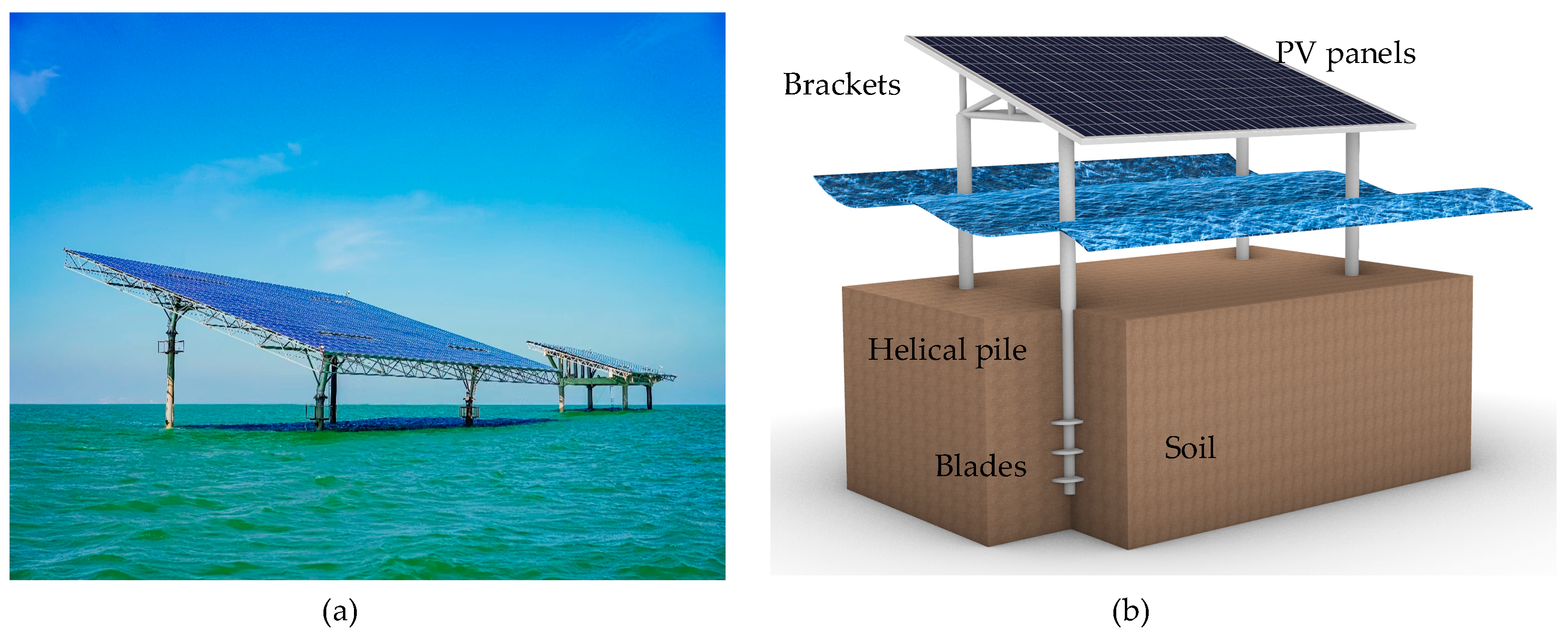
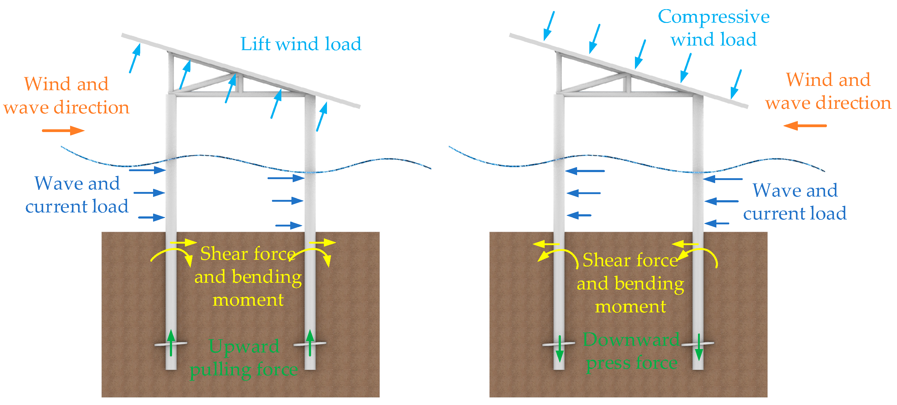
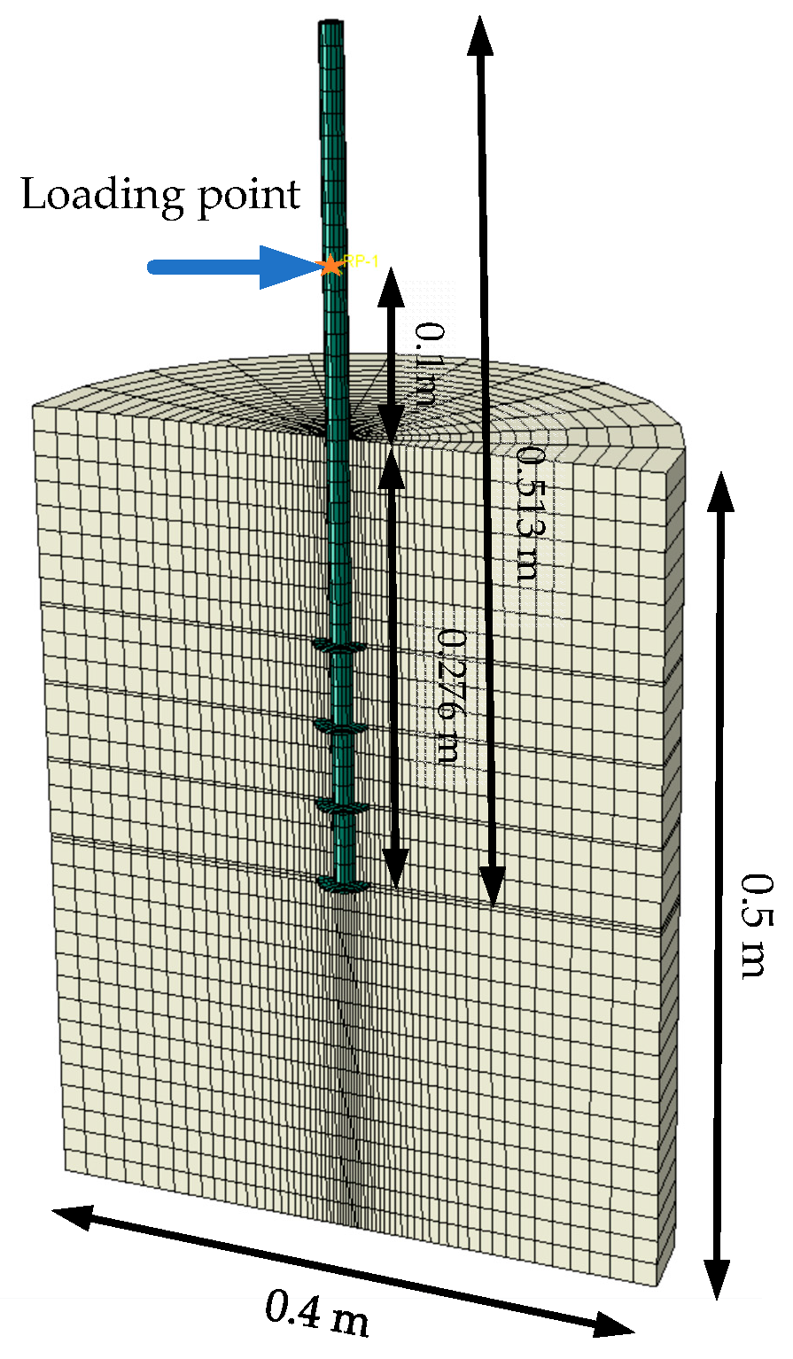
2.1. Numerical Model of the Helical Pile for Offshore PV

The offshore PV foundation consists of an upper PV bracket and four helical piles. Due to the large span of the PV bracket, every two helical piles are spaced relatively far apart, typically more than 20 times the pile shaft’s diameter, allowing the group pile effect to be ignored [21]. Therefore, for an in-depth study of the helical piles’ bearing performance under horizontal cyclic loadings, a single helical pile is chosen for the analysis. The helical pile’s diameter d is set to 0.8 m according to practical offshore PV engineering experience in Shandong Province, China (Figure 1), with the appropriate range of pile diameters (0.6–0.8 m) for offshore PV foundations. The blade diameter D is set to three times the pile’s diameter of 2.4 m. The helical pile and blades’ thickness is 3 cm, and the pitch is set to 0.3d = 0.24 m. According to the research by Merifield [22], increasing the number of blades can enhance the bearing performance to some extent, but having more than three blades increases construction difficulty. Thus, the number of blades is set to 3, with a spacing l of 2.4 m between the blades. The pile length L is 25 m, with 10 m above the seabed and 15 m embedded in the soil, and the first blade is buried at a depth of 9.2 m. The material for the helical pile and blades is steel, with a material density of 7850 kg/m3, an elastic modulus of 210 GPa, and a Poisson’s ratio of 0.3. To eliminate boundary effects, the soil region is set to a diameter of 20D = 48 m, with a height of 1.67 times the pile’s embedded depth of 25 m. The soil’s undrained shear strength Su at the mud surface is 13 kPa and increases linearly with depth, Su = 13 + 2z kPa (z is the soil depth). The saturated unit weight is 16.95 kN/m3, and the Poisson’s ratio is 0.45. Abaqus 2022 software is used to establish a 3D FEM of the helical pile and soil (Figure 3), which are modeled as three-dimensional solid elements, with the mesh type being C3D8. Soil domain size and mesh sensitivity analysis were carried out to investigate the boundary and mesh density effects. A soil size with a radius of 48 m and a mesh density of 58,208 elements is considered sufficient to avoid boundary and mesh density effects. A frictional contact algorithm featuring a contact friction coefficient of 0.3 is employed to model the interaction between the helical pile and soil. Normal contact is set to “hard contact”, allowing separation after contact. The boundary conditions impose restrictions on both horizontal and lateral displacements at the base of the soil region, with horizontal displacement constraints also applied to the sidewalls. An initial geostatic analysis is performed before applying horizontal loads to establish the soil’s initial stress fields. In addition, a simplification is made in this numerical model. Due to the irregular shape of the helical blades, if they are modeled as helical in the FEM, the qualities of the mesh elements near the blades are typically poor, leading to non-convergence or significant errors in the results. When the pitch is between 0.2d and 0.3d, the helical blades can usually be simplified as flat blades, and the bearing capacities of the simplified piles are almost the same as those of prototype ones [20,23,24].
A constitutive model for clay, which considers stiffness degradation and strain accumulation effects of clay under horizontal cyclic loading, is used in the numerical model [25,26]. The boundary surface equation in the model is expressed using the Von Mises function:
F = 3 2 s ¯ i j s ¯ i j A 0 2 = 0
In the equation, F is a function of the bounding surface based on Von Mises yield criterion; s ¯ i j are the deviatoric stress tensors on the boundary surface, i,j = 1, 2, 3 represent components of a tensor; A 0 is the radius of the boundary surface, which can be calculated with the undrained shear strength of the clay according to Equation (1), A 0 = 2 S u [27]. A schematic diagram of bounding surface and mapping rules in multidimensional stresses is shown in Figure 4, where s i j 0 , s ¯ i j , and s i j are the mapping center, image point and current point stress tensors; F / s ¯ i j are the exterior normal vectors of the bounding surface at the image stress points.
After the soil is subjected to the cyclic loading transferred by the pile foundation, the elasto-plastic shear modulus of the current stress point along the loading and unloading paths can be determined using the following interpolation function:
H = ( δ δ 0 ) μ H max e ξ d ε ¯ d p
In the equation, δ represents the distance from the current stress point to the stress point on the boundary surface; δ 0 represents the distance from the mapping center to the image stress point; μ represents the parameter that reflects the shape of the stress–strain curve during initial loading, with a value of 2 to assume that the initial shape of the stress–strain curve is a hyperbola curve; H max is the maximum elasto-plastic shear modulus; ξ reflects the rate of soil stiffness degradation and shear strain accumulation, taking the value of 0 for monotonic loading and 2 for cyclic loading. These model parameters can be obtained from dynamic triaxial test or simple shear test [25]. d ε ¯ d p is the accumulated equivalent plastic shear strain. Then, the incremental relationships between deviatoric stress and strain in the model can be expressed as
d e i j = 1 2 G d s i j + 3 2 H s ¯ i j A 0 2 s ¯ k l d s k l
In this equation, d e i j is the incremental deviatoric strain on the boundary surface; G is the elastic shear modulus of the soil and G = E / 2 ( 1 + ν ) ; E is the elastic modulus (typically taken as E = 500 S u ); ν is Poisson’s ratio, d s i j is the incremental deviatoric strain, k,l = 1, 2, 3 represent components of a tensor; H is the plastic hardening modulus, and H = 2 G H / ( 2 G H ) ; s ¯ k l is the incremental deviatoric stress on the boundary surface; and d s k l is the incremental deviatoric stress at the current stress point.

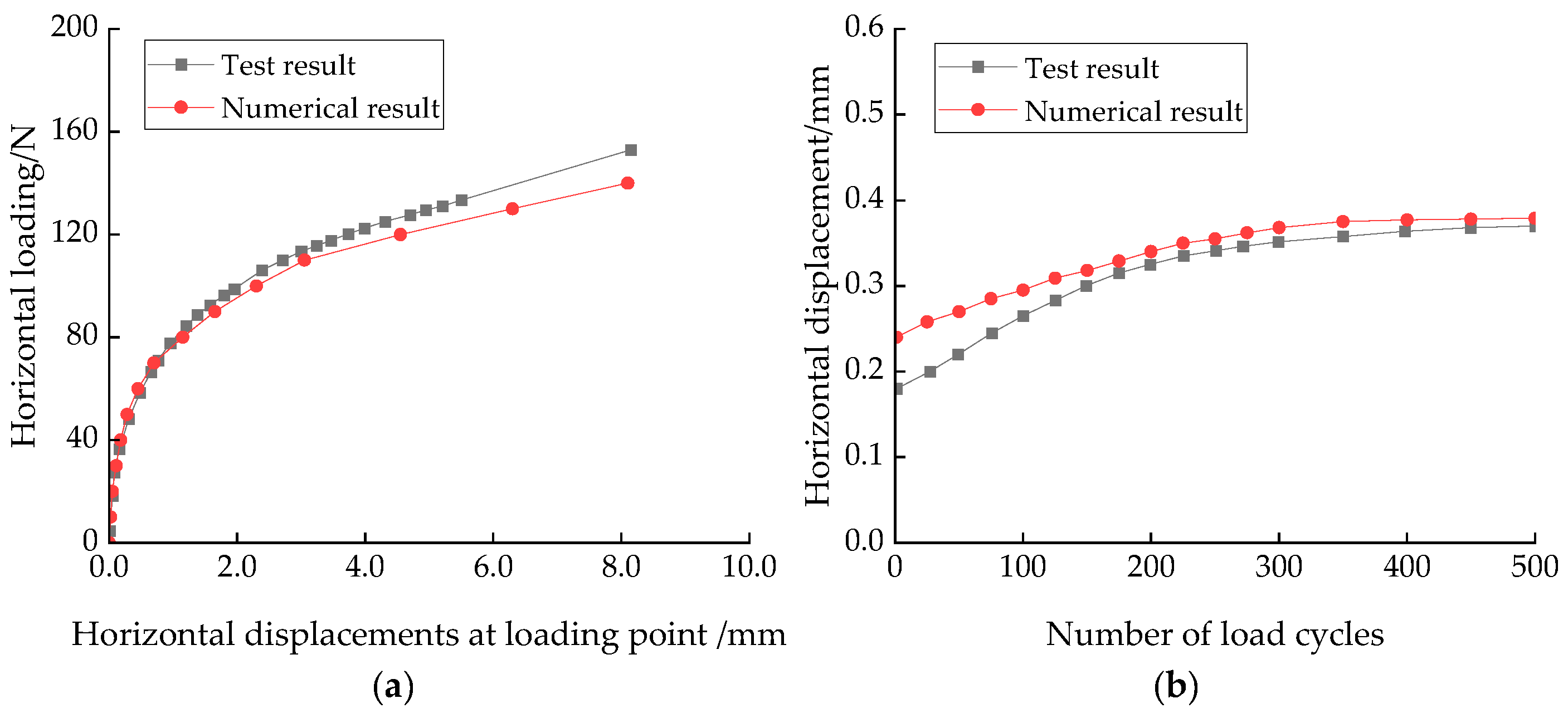
2.2. Validation of the Numerical Analysis Methods

The tests conducted by Prasad [28] under horizontal loading were selected for simulation to verify the numerical analysis methods for the performance of helical piles in clay under horizontal cyclic loadings and the effectiveness of the constitutive model of the soil. The experiment consists of tests for both monotonic loadings and horizontal cyclic loadings. The length of the helical pile is 513 mm, the diameter is 13.8 mm, and it consists of four blades. The blade diameter is 30 mm, and the spacing between the blades is 49.7 mm. The helical pile was embedded with a depth of 276 mm. The clay soil has a saturated unit weight of 16.95 kN/m3 and an undrained shear strength of 10.0 kPa. The tests were carried out in a cylindrical container measuring 400 mm in diameter and 500 mm in height. The loading point was located 100 mm above the mud surface. A corresponding 3D FEM was established, as shown in Figure 5.
During the monotonic loading test, an increasing load is applied at the loading point until the bearing capacity limit of the helical pile foundation is attained. Figure 6a compares the simulated horizontal load–displacement curves with the test under monotonic loading. It must be noted that horizontal displacements at the loading point were measured in Prasad’s test. Therefore, these displacements were compared. The figure shows that the simulated horizontal load–displacement curves agree well with the test. Plastic deformation occurs in the soil during the compression by the piles, and the horizontal load–displacement curves show a curved shape in the initial and middle stages, transitioning to a straight line at the end. The connection point between the middle curve and the final straight line can be considered the failure point, with the corresponding load representing the horizontal ultimate bearing limits. The numerical simulation shows a value of 110 N, while the experimental result is 122 N, with a difference of less than 10%.
In the horizontal cyclic loading test, the controller applied horizontal cyclic loadings with a period of 12 s at the loading point, with an amplitude of 0.4 times the horizontal ultimate bearing capacity, i.e., 48.8 N. Figure 6b compares the simulated cycle count–displacement curve with the experimental results during horizontal cyclic loadings. It is found that in the initial stage, there is a little difference between the simulated and test cycle count–displacement curves: in the numerical simulation, the helical pile produces the displacement corresponding to the static load during the first cycle, while in the experimental results, the cumulative displacement is relatively small in the initial cycles. After approximately 250 cycles, the stiffness of clay gradually stabilizes, and the helical pile’s displacements no longer increase significantly in both the numerical simulation and the experiment. The cumulative displacements obtained from the simulation agree well with those obtained from the tests.
In conclusion, for both horizontal monotonic and cyclic loading tests, the numerical results are close to the test ones regarding the horizontal displacement values and trends. This demonstrates the effectiveness of the numerical modeling and analysis method in simulating the horizontal force–deformation behavior of helical piles in clay.

3. Results

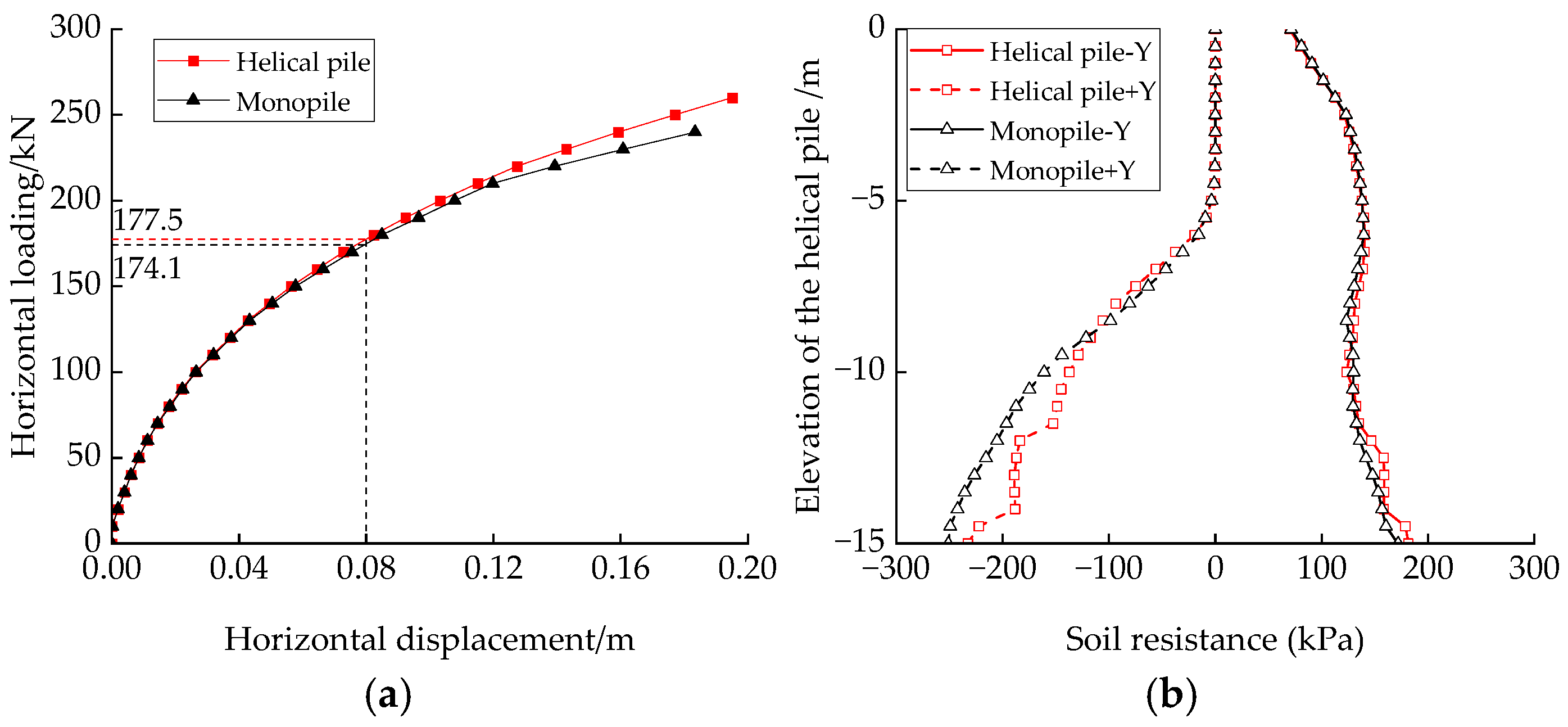
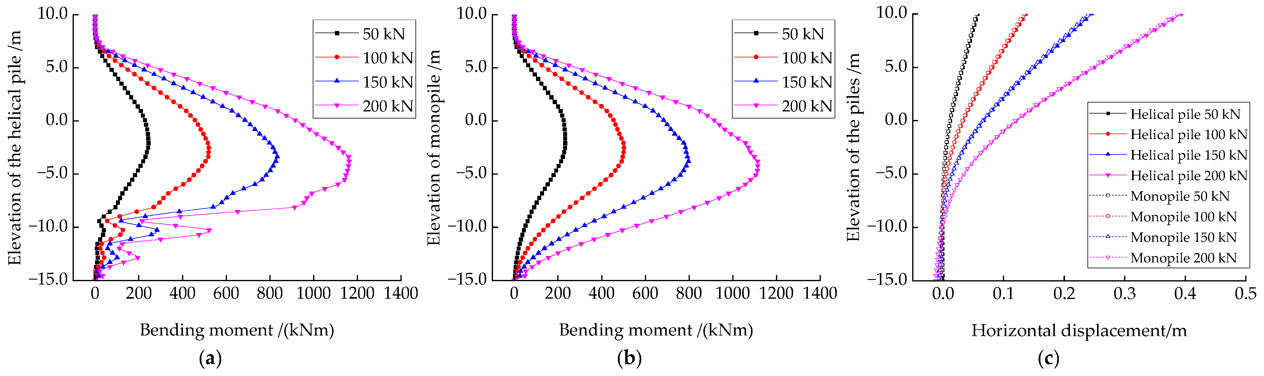
3.1. Bearing Performances of the Helical Pile under Horizontal Monotonic Loadings

To examine the ultimate horizontal bearing performances of a single helical pile under horizontal loading, as described in Section 2.1, a corresponding monopile without blades is also established for comparison. The monopile model’s diameter, wall thickness, and soil parameters are the same. A monotonically increasing horizontal load along the positive Y direction is applied at the 7.0 m height above the mud surface (representing the combined loading point of the wind and wave forces) until the ultimate horizontal bearing limit is reached with a load increment of 10 kN at each step.
Figure 7a shows the helical pile and monopile’s horizontal load–displacement curves at the mud surface. The figure shows that displacements at the mud surface increase gradually with horizontal load, showing no distinct yield point or turning point in the bearing capacity. Considering that the offshore PV foundation is controlled by the serviceability limit state (SLS) and strict regulations exist on the pile foundation’s horizontal displacements, the horizontal bearing capacity is defined based on the horizontal displacement at the mudline. For piles subjected to horizontal loads, Byrne suggested using the displacements corresponding to 10% of the piles’ diameters at the mudline as the horizontal bearing limits in the SLS [29]. In Figure 7a, it is found that the horizontal bearing capacities in the SLS for the helical pile and monopile (FSLS) are 177.5 kN and 174.1 kN, respectively. These values will be used as the standard to determine the amplitude of the subsequent horizontal cyclic loadings. Additionally, it is noted that the increase in the horizontal bearing limit of the helical pile, compared to the monopile under monotonic horizontal loading, is quite minimal. This is mainly due to the smaller diameter and larger length-to-diameter ratio of the offshore PV piles foundation, which exhibits the bearing performance of a flexible pile under horizontal loadings. As the horizontal displacements of the piles increase, the soil resistance shifts deeper until reaching the blades (Figure 7b). The horizontal displacements of the helical pile under the static loadings of 50 kN, 100 kN, 150 kN, and 200 kN, respectively, are shown in Figure 8. The horizontal displacements gradually increase as the load increases. A similar trend of piles’ Von Mises stress is shown in Figure 9.
Figure 10 shows the bending moments distribution and horizontal displacement along the piles’ shafts under different horizontal load amplitudes. The bending moment is derived from the stresses of the piles. As the load increases, the bending moments of both pile foundations increase, and the depth of soil layers where maximum bending moments occur gradually increases. Comparing Figure 10a,b, it can be seen that at a lower load amplitude (50 kN), the bending moments at the blade position of the helical pile change slightly and are similar to that of the monopile. However, as the load amplitude increases, the blades gradually contribute to the bearing capacity, and the bending moment at the blade height increases accordingly. In Figure 10c, the influence depth of the soil increases as the load amplitude increases. There is little difference in horizontal displacements along the piles’ shaft in helical piles and monopiles in monotonic loading cases.

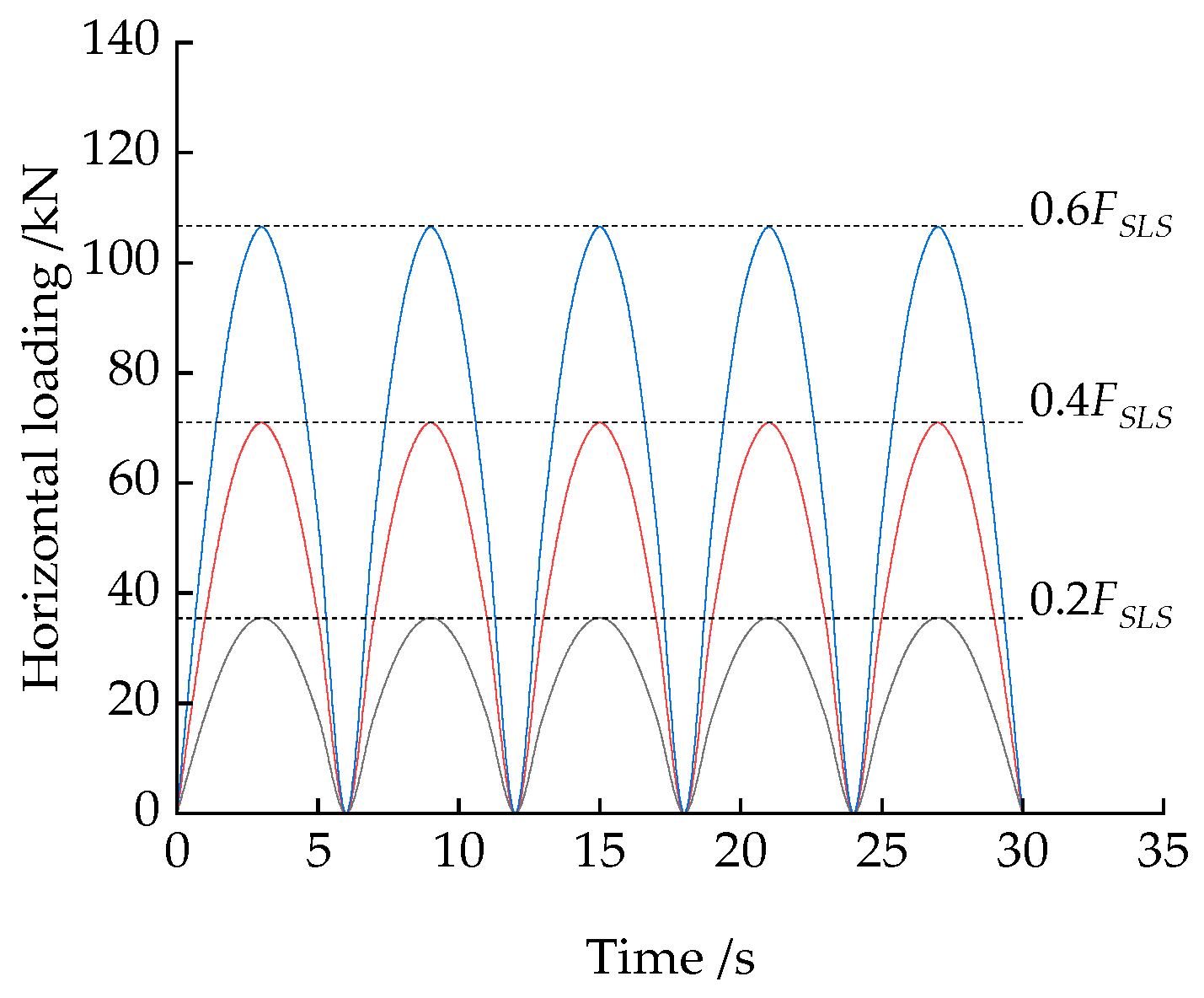
3.2. Bearing Performances of the Helical Pile under Horizontal Cyclic Loadings

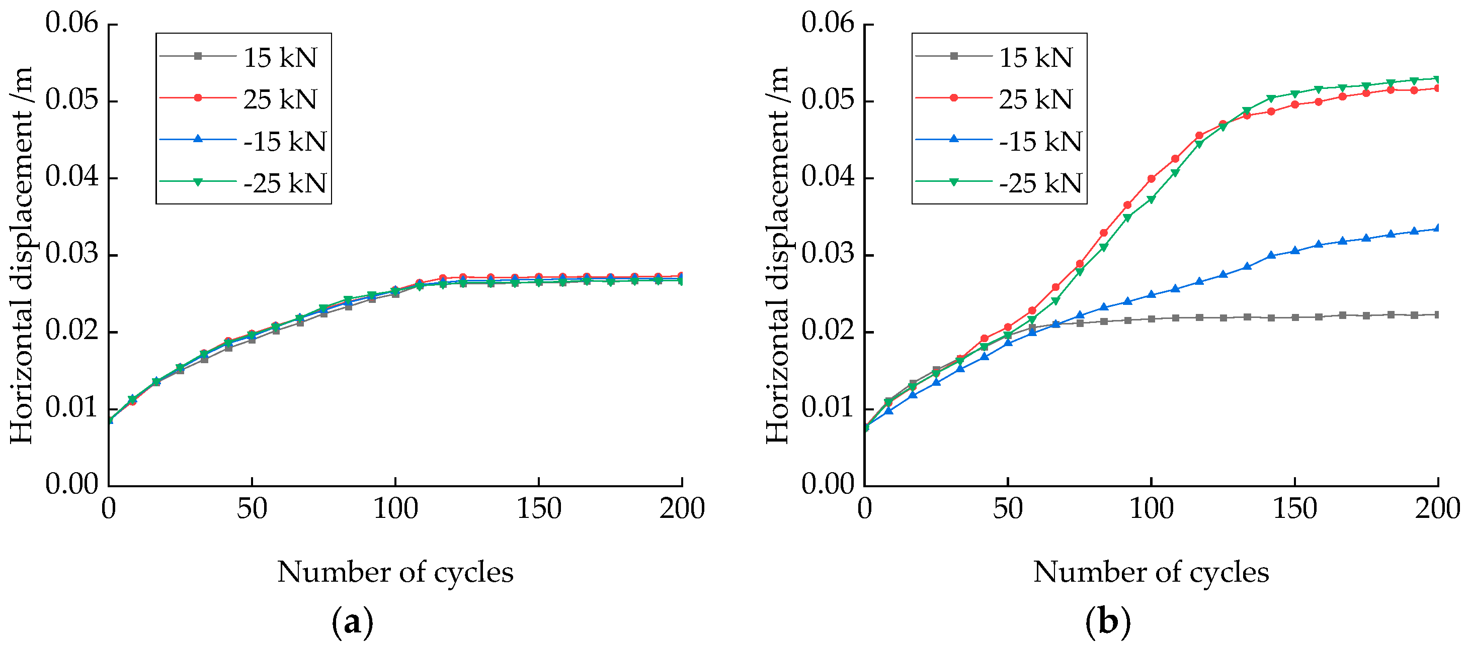
3.2.1. Effects of Cyclic Loadings Amplitude on Horizontal Bearing Performances

To study the effects of cyclic loadings amplitude on horizontal bearing performances of the piles, semi-sinusoidal horizontal cyclic loadings with amplitudes of 0.2 FSLS, 0.4 FSLS, and 0.6 FSLS, and a period of 6 s are applied at the loading point mentioned earlier. The time history curves of the applied horizontal cyclic loadings for the first five cycles are illustrated in Figure 11.
Figure 12 shows the horizontal displacements at the mud surface for the piles under different cyclic loading amplitudes. With the increase in the number of cycles, the horizontal displacements of both piles at the mud surface increase. This is due to the degradation of soil stiffness under cyclic compression of piles, leading to the accumulation of irreversible plastic deformations. For the helical pile, under a smaller cyclic loading amplitude (0.2FSLS), the soil stiffness tends to stabilize after a certain number of cycles, and the horizontal displacement no longer increases. However, under a larger cyclic loading amplitude (0.6FSLS), the number of cycles required for the horizontal displacements at the mudline to stabilize increases. The displacement after stabilization is slightly greater than the horizontal displacement corresponding to that in the SLS. For the monopile, under a smaller cyclic loading amplitude (0.2FSLS), the horizontal displacement at the mud surface is similar to that of the helical pile. The displacement stabilizes after a specific number of cycles. Under a medium cyclic loading amplitude (0.4FSLS), the number of cycles to stabilize increases. Under a larger cyclic loading amplitude (0.6FSLS), the horizontal displacement increases and does not stabilize within 200 cycles, exceeding the horizontal displacement corresponding to that in the SLS. This represents that the helical piles’ bearing capacity under horizontal cyclic loadings is approximately 60% of its static bearing capacity, whereas the monopile’s bearing capacity under cyclic loading is less than 60% of its static bearing capacity. This occurs because, at larger cyclic loading amplitudes, the degradation of soil stiffness becomes more evident as the number of cycles increases, leading to a rise in the accumulation of plastic strain. Although the applied load amplitude does not exceed the monotonic loading limits, cumulative horizontal displacements exceed the displacement corresponding to the SLS after a specific number of cycles. Figure 13 shows horizontal displacements of piles and soil after 100 load cycles under different load amplitudes. Under larger cyclic loading amplitudes (0.6FSLS), the helical pile exhibits more stability due to the blades’ increased pile–soil interaction area. For the helical pile, the influenced soil zone has a depth of 7.8 m. Meanwhile, for the monopile, the depth increases to 8.5 m. Figure 14 shows the Von Mises stresses of the helical pile and the monopile. Under a smaller cyclic loading amplitude (0.2FSLS), the Von Mises stress of the helical pile near the blade is slightly larger than the Von Mises stress of the monopile. When the cyclic loading amplitude increases, the maximum stress point shifts up for both piles. The helical pile shows a lower stress than the monopile under larger cyclic loadings.
Figure 15 shows the bending moment distribution along the piles’ shaft after 100 cycles under different load amplitudes. It is found that the bending moments of both piles increase with the load amplitude. In the shallowly buried region (above −5 m), the helical pile’s bending moments are slightly larger than those of the monopile. However, in deeper buried regions, the helical pile’s bending moments are smaller than those of the monopile due to the presence of blades.

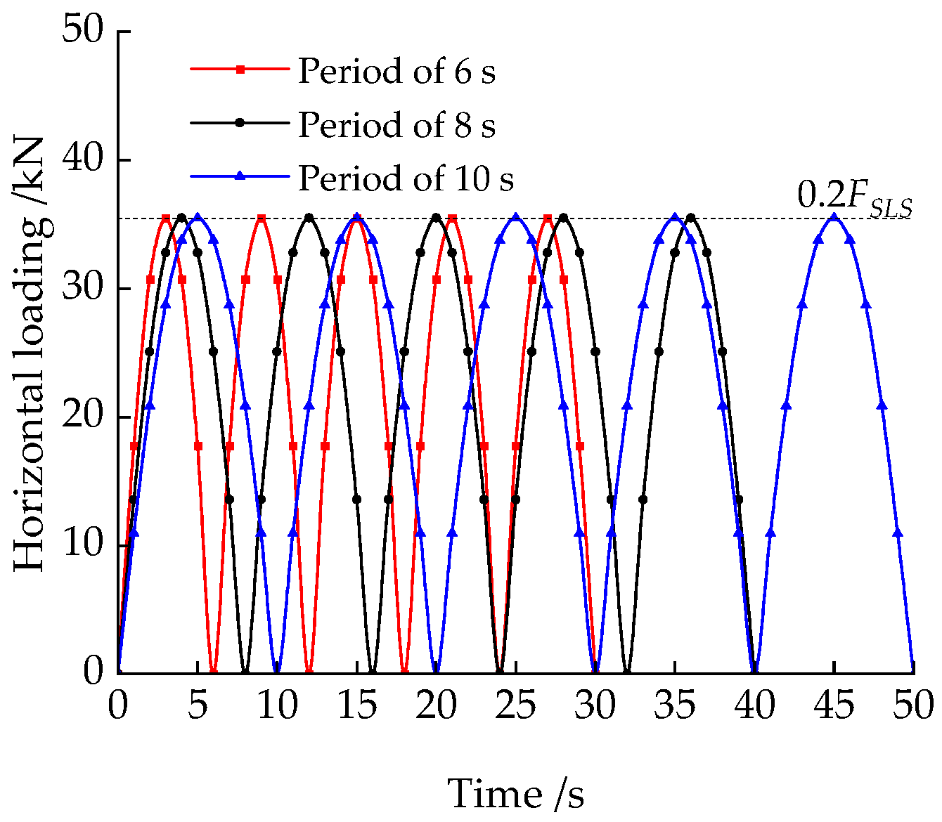
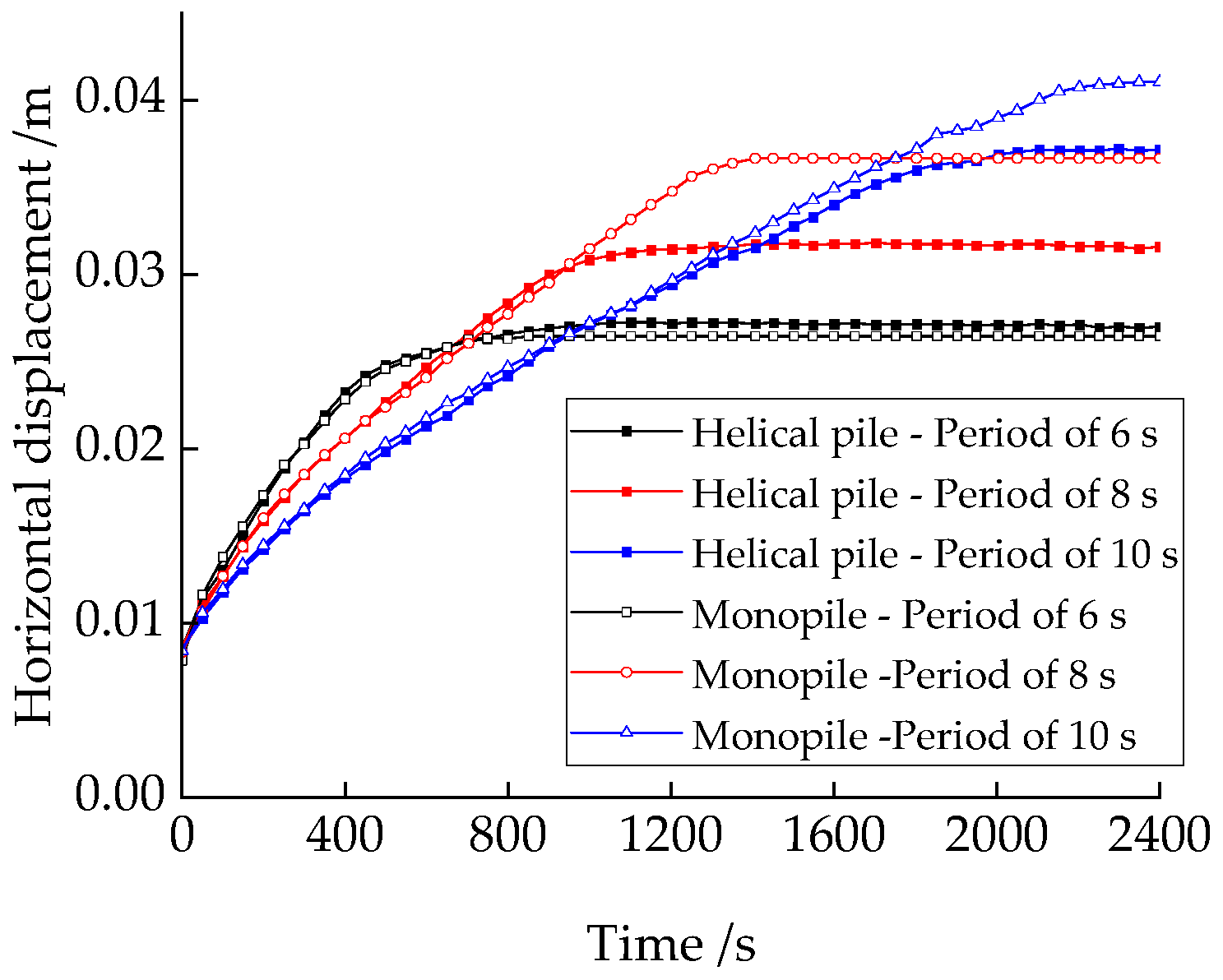
3.2.2. Effects of Cyclic Loadings Period on Horizontal Bearing Performances

To analyze the effects of cyclic loadings period on horizontal bearing performances of the piles, semi-sinusoidal horizontal cyclic loads with an amplitude of 0.2 FSLS and periods of 6 s, 8 s, and 10 s were applied at the previously mentioned load point. The time history curves of the applied horizontal cyclic loads for the first five cycles are shown in Figure 16.
Figure 17 shows the horizontal displacements at the mud surface for the helical pile and monopile under different cyclic loading periods. For different load periods, both piles follow the same pattern: the smaller the cyclic loading period, the larger the accumulation of horizontal displacements in an initial phase, and the faster it stabilizes. Conversely, the larger the cyclic loading period, the smaller the initial accumulated horizontal displacements, but the accumulated displacements at stabilization are more significant. Comparing the time history curves of horizontal displacements for the helical pile and monopile, when the period is short (6 s), the accumulated displacements of the monopile are slightly smaller than those of the helical pile. However, for longer periods (8 s and 10 s), the helical pile stabilizes in fewer cycles and has a better accumulated displacement performance than the monopile. Figure 18 shows the horizontal displacements of the piles and soil after 100 load cycles under different load periods. Within the first 100 cycles, the period has a minor effect on the amplitude of horizontal displacement. A similar trend of piles’ Von Mises stress is shown in Figure 19. The Von Mises stress of the helical pile near the blade is slightly larger than the Von Mises stress of the monopile due to the gravity of the soil on top of the blades.
Figure 20 shows the bending moment distribution along the shafts of the piles after 100 cycles under different load periods. It can be observed that the loading period has little effect on the bending moments of the pile shaft, and the bending moments are mainly influenced by the amplitudes of the cyclic loadings.

3.2.3. Effects of Vertical Loads on Horizontal Bearing Performances

Due to the tilt and large area of offshore PV panels, wind loads cause significant vertical uplift or downward loads on the helical pile head. These vertical loads can affect the horizontal bearing performance of the helical pile under cyclic loadings. For a typical offshore PV system with a length of 20 m, a width of 15 m, and an inclination angle of 15°, under SLS (Serviceability Limit State) conditions, the vertical wind load component is about 100 kN. This load is distributed across four piles, with 25 kN on each pile. To analyze the impacts of vertical loads on the horizontal bearing performances of helical piles, constant vertical loads of 15 kN, 25 kN, −15 kN, and −25 kN were applied along with a horizontal cyclic loading of 0.2 FSLS and a period of 6 s. A positive value indicates an upward vertical load, while a negative value indicates a downward vertical load.
Figure 21 shows the horizontal displacements at the mud surface for the helical pile and monopile under the combined action of different vertical loads and horizontal cyclic loadings. The amplitude and direction of the vertical loads have little impact on the horizontal cyclic bearing performances of the helical pile, as shown in Figure 21a. This is mainly because the blades of the helical pile provide significant uplift and compression resistance (Figure 22a,b). The blades prevent large shear forces around the pile’s shaft, and the clay does not experience significant shear failure, allowing it to provide substantial horizontal resistance. In contrast, in Figure 21b, the horizontal bearing performance of the monopile is not significantly affected by small vertical loads. However, under larger vertical loads, whether upward or downward, the horizontal displacement of the monopile increases, reducing its horizontal bearing capacity. This is because large vertical loads combined with horizontal cyclic loads cause shear deformation in the shallow soil around the pile shaft, leading to rapid soil stiffness degradation and significant cumulative horizontal displacement (Figure 22c,d). However, the vertical load shows little effect on the piles’ Von Mises stress (Figure 23).
Figure 24 shows the bending moment distribution along the piles’ shafts after 200 cycles under different vertical loads. In the soil layer above −5 m, the bending moments of the helical pile are greater than that of the monopile, validating the earlier hypothesis that in the monopile, the shallow soil stiffness degrades significantly, causing the load-bearing soil layer to move downward. For the monopile, the bending moments rapidly increase to a peak after −5 m and then decrease. The bending moments in the lower section of the helical pile are lower than those in the monopile due to the presence of blades.

4. Conclusions

This study focuses on the helical pile for offshore PV. A numerical analysis method is proposed to evaluate the horizontal bearing performance of the helical pile in clay under horizontal cyclic loadings using an elasto-plastic boundary surface constitutive model for the clay. This study investigates the effects of the cyclic loading amplitude, load period, and vertical load on the horizontal bearing performance of helical piles. The key conclusions can be summarized as follows:
  • Under horizontal monotonic loading, the bearing performance of the helical pile and monopile with the same diameter shows little difference in the serviceability limit state.
  • Under small horizontal cyclic loadings, the stiffness of the soil around piles stabilizes after a certain number of cycles, and the horizontal displacement no longer increases. Under larger cyclic loads, the stiffness of the soil degrades significantly, leading to more significant accumulated plastic deformation. The horizontal bearing capacity of the helical pile under cyclic loading is approximately 60% of its capacity under monotonic loading, whereas the monopile’s capacity under cyclic loading is less than 60% of its monotonic loading capacity.
  • The shorter the cyclic loading period, the greater the initial horizontal displacement accumulation, and the sooner stability is reached. Conversely, the longer the cyclic loading period, the smaller the initial horizontal displacement accumulation, but the accumulated displacement at stabilization is more significant.
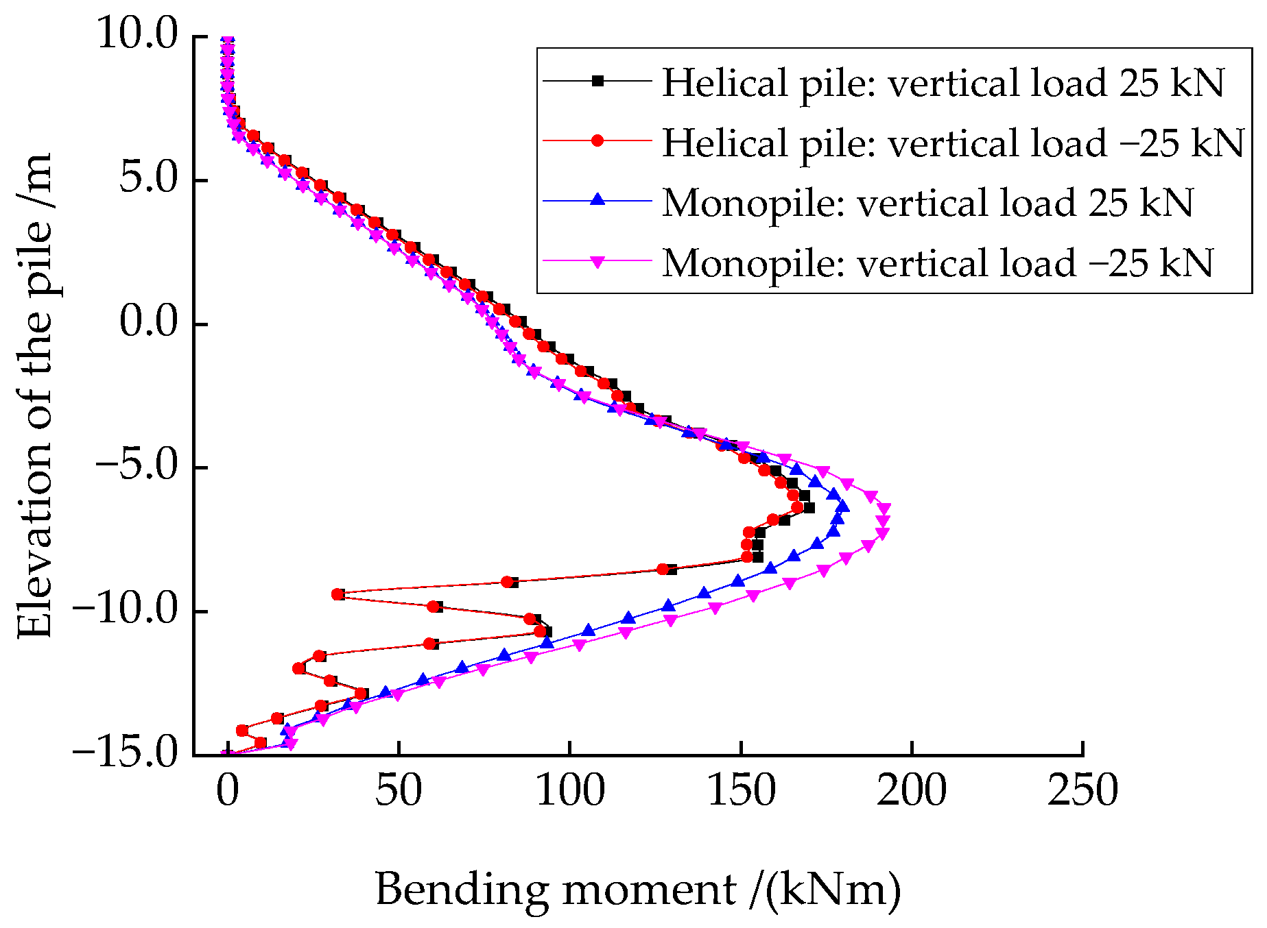
  • The horizontal cyclic bearing performance of the monopile is greatly affected by vertical loads. However, due to the uplift and compressive resistance provided by the blades, vertical loads have little effect on the horizontal cyclic bearing performance of the helical pile, which exhibits a more stable horizontal cyclic bearing performance.

Author Contributions

Conceptualization, X.C. and Y.H.; Methodology, Y.H.; Software, Z.L. and J.L.; Validation, J.L.; Resources, Z.A.; Writing—original draft, X.C.; Writing—review and editing, Z.L. and Z.A.; Supervision, Y.H.; Funding acquisition, X.C. All authors have read and agreed to the published version of the manuscript.

Funding

This research was funded by the National Natural Science Foundation of China, grant number 51809315, and The Natural Science Foundation of Shandong Province, grant number ZR2023QE063.

Data Availability Statement

The dataset is available upon request from the authors.

Conflicts of Interest

Authors Xinfu Cong, Zhe Li, Zhonghai An were employed by the company Shandong Electric Power Engineering Consulting Institute Co., Ltd. The remaining authors declare that the research was conducted in the absence of any commercial or financial relationships that could be construed as a potential conflict of interest.

References

  1. Wang, J.; Lund, P.D. Review of Recent Offshore Photovoltaics Development. Energies 2022, 15, 7462. [Google Scholar] [CrossRef]
  2. Ghosh, A. A comprehensive review of water based PV: Flotavoltaics, under water, offshore & canal top. Ocean Eng. 2023, 281, 115044. [Google Scholar]
  3. Kjeldstad, T.; Lindholm, D.; Marstein, E.; Selj, J. Cooling of floating photovoltaics and the importance of water temperature. Sol. Energy 2021, 218, 544–551. [Google Scholar] [CrossRef]
  4. Du, J.; Zhang, D.; Zhang, Y.; Xu, K.; Chang, A.; Zhao, S. Design and comparative analysis of alternative mooring systems for offshore floating photovoltaics arrays in ultra-shallow water with significant tidal range. Ocean Eng. 2024, 302, 117649. [Google Scholar] [CrossRef]
  5. Zheng, Z.; Jin, P.; Huang, Q.; Zhou, B.; Xiang, R.; Zhou, Z.; Huang, L. Motion response and energy harvesting of multi-module floating photovoltaics in seas. Ocean Eng. 2024, 310, 118760. [Google Scholar] [CrossRef]
  6. Feng, S.-J.; Fu, W.-D.; Chen, H.-X.; Li, H.-X.; Xie, Y.-L.; Lv, S.-F.; Li, J. Field tests of micro screw anchor piles under different loading conditions at three soil sites. Bull. Eng. Geol. Environ. 2021, 80, 127–144. [Google Scholar] [CrossRef]
  7. Vignesh, V.; Mayakrishnan, M. Design parameters and behavior of helical piles in cohesive soils—A review. Arab. J. Geosci. 2020, 13, 1194. [Google Scholar] [CrossRef]
  8. Byrne, B.W.; Houlsby, G.T. Helical piles: An innovative foundation design option for offshore wind turbines. Philos. Trans. R. Soc. A Math. Phys. Eng. Sci. 2015, 373, 20140081. [Google Scholar] [CrossRef]
  9. Spagnoli, G.; de Hollanda Cavalcanti Tsuha, C. A review on the behavior of helical piles as a potential offshore foundation system. Mar. Georesour. Geotechnol. 2020, 38, 1013–1036. [Google Scholar] [CrossRef]
  10. Kumar, T.J.; Deendayal, R.; Sahoo, S.K. Behaviour of a laterally loaded rigid helical pile located on a sloping ground surface. Mar. Georesour. Geotechnol. 2024, 1–20. [Google Scholar] [CrossRef]
  11. Ren, G.; Wang, Y.; Tang, Y.; Zhao, Q.; Qiu, Z.; Luo, W.; Ye, Z. Research on Lateral Bearing Behavior of Spliced Helical Piles with the SPH Method. Appl. Sci. 2022, 12, 8215. [Google Scholar] [CrossRef]
  12. Lin, Y.F.; Xiao, J.D.; Le, C.H.; Zhang, P.Y.; Chen, Q.S.; Ding, H.Y. Bearing Characteristics of Helical Pile Foundations for Offshore Wind Turbines in Sandy Soil. J. Mar. Sci. Eng. 2022, 10, 889. [Google Scholar] [CrossRef]
  13. Elkasabgy, M.; El Naggar, H. Axial compressive response of large-capacity helical and driven steel piles in cohesive soil. Can. Geotech. J. 2015, 52, 224–243. [Google Scholar] [CrossRef]
  14. Ding, H.; Wang, L.; Zhang, P.; Le, C. Study on the Lateral Bearing Capacity of Single-Helix Pile for Offshore Wind Power. In Proceedings of the Volume 9: Offshore Geotechnics; Honoring Symposium for Professor Bernard Molin on Marine and Offshore Hydrodynamics, Madrid, Spain, 17–22 June 2018. [Google Scholar]
  15. Wang, L.; Zhang, P.Y.; Ding, H.Y.; Tian, Y.H.; Qi, X. The uplift capacity of single-plate helical pile in shallow dense sand including the influence of installation. Mar. Struct. 2020, 71, 102697. [Google Scholar] [CrossRef]
  16. Rao, S.N.; Prasad, Y.V.S.N. Behavior of a helical anchor under vertical repetitive loading. Mar. Geotechnol. 1991, 10, 203–228. [Google Scholar] [CrossRef]
  17. Wada, M.; Tokimatsu, K.; Maruyama, S.; Sawaishi, M. Effects of cyclic vertical loading on bearing and pullout capacities of piles with continuous helix wing. Soils Found. 2017, 57, 141–153. [Google Scholar] [CrossRef]
  18. Hao, D.; Che, J.; Chen, R.; Zhang, X.; Yuan, C.; Chen, X. Experimental Investigation on Behavior of Single-Helix Anchor in Sand Subjected to Uplift Cyclic Loading. J. Mar. Sci. Eng. 2022, 10, 1338. [Google Scholar] [CrossRef]
  19. Yang, X.Y.; Wang, C.Z.; Cao, S.; Wang, F.X.; Wu, W.B.; Luongo, A.; Zhao, Y.L.; Wang, Y.X.; Lin, H.; Guo, P.P. Lateral Dynamic Response of Helical Pile in Viscoelastic Foundation Considering Shear Deformation. Appl. Sci. 2023, 13, 12220. [Google Scholar] [CrossRef]
  20. Al-Baghdadi, T.A.; Brown, M.J.; Knappett, J.A.; Al-Defae, A.H. Effects of vertical loading on lateral screw pile performance. Proc. Inst. Civ. Eng. Geotech. Eng. 2017, 170, 259–272. [Google Scholar] [CrossRef]
  21. American Petroleum Institute. Planning, Designing, and Constructing Fixed Offshore Platforms: Working Stress Design; American Petroleum Institute: Washington, DC, USA, 2020. [Google Scholar]
  22. Merifield, R.S. Ultimate Uplift Capacity of Multiplate Helical Type Anchors in Clay. J. Geotech. Geoenviron. Eng. 2011, 137, 704–716. [Google Scholar] [CrossRef]
  23. Venkatesan, V.; Mayakrishnan, M. Behavior of Mono Helical Pile Foundation in Clays under Combined Uplift and Lateral Loading Conditions. Appl. Sci. 2022, 12, 6827. [Google Scholar] [CrossRef]
  24. George, B.E.; Banerjee, S.; Gandhi, S.R. Numerical analysis of helical piles in cohesionless soil. Int. J. Geotech. Eng. 2020, 14, 361–375. [Google Scholar] [CrossRef]
  25. Cheng, X.; Du, X.; Lu, D.; Ma, C.; Wang, P. A simple single bounding surface model for undrained cyclic behaviours of saturated clays and its numerical implementation. Soil Dyn. Earthq. Eng. 2020, 139, 106389. [Google Scholar] [CrossRef]
  26. Cheng, X.; Wang, T.; Zhang, J.; Liu, Z.; Cheng, W. Finite element analysis of cyclic lateral responses for large diameter monopiles in clays under different loading patterns. Comput. Geotech. 2021, 134, 104104. [Google Scholar] [CrossRef]
  27. Das, B.M. Advanced Soil Mechanics, 5th ed.; CRC Press: London, UK, 2019. [Google Scholar]
  28. Prasad, Y.V.S.N.; Rao, S.N. Pullout behaviour of model pile and helical pile anchors Subjected to lateral cyclic loading. Can. Geotech. J. 1994, 31, 110–119. [Google Scholar] [CrossRef]
  29. Byrne, B.W.; McAdam, R.A.; Burd, H.J.; Houlsby, G.T.; Martin, C.M.; Gavin, K.; Doherty, P.; Igoe, D.; Zdravkovi, L.; Taborda, D.M.G.; et al. Field testing of large diameter piles under lateral loading for offshore wind applications. In Proceedings of the Geotechnical Engineering for Infrastructure and Development, Edinburgh, UK, 13–17 September 2015; ICE Publishing: London, UK, 2015; Volume 1–7, pp. 1255–1260. [Google Scholar]
Figure 1. Fixed offshore PV: (a) First fixed offshore PV in Shandong Province, China; (b) Helical piles for fixed offshore PV foundation.
Jmse 12 01826 g001
Figure 2. Offshore PV helical pile foundation subjected to wind, wave, and current loads.
Jmse 12 01826 g002
Figure 3. 3D FEM of the helical pile foundation in clay.
Jmse 12 01826 g003
Figure 4. A schematic diagram of bounding surface and mapping rules in multidimensional stresses.
Jmse 12 01826 g004
Figure 5. The 3D FEM of the validation test.
Jmse 12 01826 g005
Figure 6. Comparisons of simulation results with test results: (a) Load–displacement curves under monotonic loading; (b) Cycle number-displacement curves under horizontal cyclic loading.
Jmse 12 01826 g006
Figure 7. (a) Horizontal load–displacement curve of the piles at mud surface and (b) soil resistance along the piles’ shaft in SLS.
Jmse 12 01826 g007
Figure 8. Horizontal displacements of the helical pile under static loadings of (a) 50 kN, (b) 100 kN, (c) 150 kN, and (d) 200 kN, respectively.
Jmse 12 01826 g008
Figure 9. Von Mises stress of the helical pile under static loadings of (a) 50 kN, (b) 100 kN, (c) 150 kN, and (d) 200 kN, respectively.
Jmse 12 01826 g009
Figure 10. Distribution of bending moments with height for (a) helical pile and (b) monopile under different horizontal load amplitudes, and (c) horizontal displacements along the piles’ shaft.
Jmse 12 01826 g010
Figure 11. Time histories of horizontal cyclic loadings with different amplitudes (first 5 cycles).
Jmse 12 01826 g011
Figure 12. Horizontal displacements at the mud surface of piles under different load amplitudes.
Jmse 12 01826 g012
Figure 13. Horizontal displacements after 100 cycles with different load amplitudes: (a) Helical pile 0.2FSLS, (b) Helical pile 0.4FSLS, (c) Helical pile 0.6FSLS, (d) Monopile 0.2FSLS, (e) Monopile 0.4FSLS, and (f) Monopile 0.6FSLS, respectively.
Jmse 12 01826 g013
Figure 14. Von Mises stress of the piles after 100 cycles with different load amplitudes: (a) Helical pile 0.2FSLS, (b) Helical pile 0.4FSLS, (c) Helical pile 0.6FSLS, (d) Monopile 0.2FSLS, (e) Monopile 0.4FSLS, and (f) Monopile 0.6FSLS, respectively.
Jmse 12 01826 g014
Figure 15. Bending moment distribution of helical pile and monopile after 100 load cycles under different load amplitudes.
Jmse 12 01826 g015
Figure 16. Time histories of applied horizontal cyclic loadings with different periods (first 5 cycles).
Jmse 12 01826 g016
Figure 17. Time history of horizontal displacement of the helical pile and monopile at mud surface under different load periods.
Jmse 12 01826 g017
Figure 18. Horizontal displacements after 100 cycles with different load periods: (a) Helical pile, 6 s; (b) Helical pile, 8 s; (c) Helical pile, 10 s; (d) Monopile, 6 s; (e) Monopile, 8 s; and (f) Monopile, 10 s, respectively.
Jmse 12 01826 g018
Figure 19. Von Mises stress of the piles after 100 cycles with different load amplitudes: (a) Helical pile, 0.2FSLS; (b) Helical pile, 0.4FSLS; (c) Helical pile, 0.6FSLS; (d) Monopile, 0.2FSLS; (e) Monopile, 0.4FSLS; and (f) Monopile, 0.6FSLS, respectively.
Jmse 12 01826 g019
Figure 20. Bending moment distribution of helical pile and monopile after 100 cycles under different loading periods.
Jmse 12 01826 g020
Figure 21. Time history of horizontal displacement of (a) helical pile and (b) monopile at mud surface under different vertical loads.
Jmse 12 01826 g021
Figure 22. Horizontal displacements after 200 cycles with different vertical loads: (a) Helical pile 25, kN; (b) Helical pile, −25 kN; (c) Monopile, 25 kN; and (d) Monopile, −25 kN, respectively.
Jmse 12 01826 g022
Figure 23. Von Mises stress of the piles after 200 cycles with different vertical loads: (a) Helical pile, 25 kN; (b) Helical pile, −25 kN; (c) Monopile, 25 kN; and (d) Monopile, −25 kN, respectively.
Jmse 12 01826 g023
Figure 24. Bending moment distribution of helical pile and monopile after 200 load cycles under different vertical loads.
Jmse 12 01826 g024
Disclaimer/Publisher’s Note: The statements, opinions and data contained in all publications are solely those of the individual author(s) and contributor(s) and not of MDPI and/or the editor(s). MDPI and/or the editor(s) disclaim responsibility for any injury to people or property resulting from any ideas, methods, instructions or products referred to in the content.

