Abstract
To make an Autonomous Underwater Vehicle (AUV) chase a moving target ship that generates wake, wake-responsive guidance can be used. This scenario is applicable to making an underwater torpedo pursue a moving target ship until hitting the target. The objective of our research is to make an AUV pursue a target ship assisted by passive sonar sensors as well as wake sensors. To track a maneuvering target without losing the target, the AUV applies both passive sonar sensors and two wake sensors. Two wake sensors are utilized to decide the turn direction of the AUV in zig-zag maneuvers. In practice, sharp maneuvers of the target can cause the AUV to exit the target’s wake abruptly. As the target ship’s wake is not detected by wake sensors and the AUV needs to search for the target ship, the AUV’s passive sonar measures the direction of sound generated from the target ship. Thereafter, the AUV chases the target ship until the target’s wake is detected again. As far as we know, our paper is novel in addressing wake-responsive AUV guidance assisted by passive sonar sensors. The effectiveness of the proposed guidance is verified using computer simulations.
1. Introduction
Torpedoes have been developed to attack a surface target ship [1,2,3,4,5]. A torpedo can be considered a fast autonomous underwater vehicle (AUV) heading towards the target ship. Therefore, control of an AUV [6,7,8,9,10] can be applied to the control of a torpedo.
To make an AUV chase a moving target ship that generates wake, wake-responsive guidance can be used. This scenario is applicable in making an underwater torpedo pursue a moving target ship until hitting the target.
The authors of [4] addressed the initial concept of wake-responsive AUVs. The wake of a moving target ship generally generates a source of spurious information and disturbing signals, interfering with the operation of active marine torpedo-guiding systems [4]. Torpedoes equipped with active homing systems can be misdirected due to various disturbances as they pass through the target ship’s wake. Therefore, Ref. [4] introduced a torpedo-guiding system that not only does not suffer from this defect but actually utilizes the wakes disturbance as a means of guidance.
In [4], a zig-zag pursuit maneuver was developed to make a wake-responsive AUV follow the target ship’s wake until contact. However, this zig-zag guidance proposed in [4] is not suitable for chasing a maneuvering target ship. As the target ship maneuvers sharply, the AUV may exit the target ship’s wake, followed by losing track of the target ship.
The objective of our research is to make the AUV pursue a target ship assisted by passive sonar sensors as well as wake sensors. To track a maneuvering target ship without losing the target track, our article makes the AUV use both passive sonar sensors and two wake sensors. In our paper, the AUV has a wake sensor on either side in order to detect the wake of the target ship. Each wake sensor detects only the presence of the wake; the direction and intensity of ship wake are not detected [11]. Using two wake sensor measurements, the AUV determines whether it will turn left or right in zig-zag maneuvers.
In practice, sharp maneuvers of the target can cause the AUV exit the target’s wake abruptly. As the wake is not detected by wake sensors and the AUV needs to search for the target ship, the AUV’s passive sonar measures the direction of sound generated from the target ship. Thereafter, the AUV chases the target ship until the target ship’s wake is detected again.
To the best of our knowledge, there are only a few papers on the control of wake-responsive AUVs. The authors of [12] introduced an evaluation model for multiple wake-responsive AUVs. In [12], the launch angle with the highest probability of hitting the target ship was computed. The authors of [1] addressed guiding methods for a wire-guided, wake-homing AUV. In [1], wire guidance was used until the AUV detected the wake of the target ship. However, Ref. [1] did not consider the case where the AUV loses the wake of the target ship due an abrupt maneuver of the target. In [11], a virtual wake boundary trajectory was generated using the wake boundary points passed by the AUV. This virtual wake boundary was used in the AUV guidance method described in [11]. However, as the target ship maneuvers sharply, this virtual wake boundary diverges from true target trajectory. Therefore, a virtual wake boundary cannot be used to track a target ship that maneuvers sharply. As far as we know, our paper is novel in using passive sonar sensors to compensate for the case where the target ship’s wake is not detected by two wake sensors.
In our paper, passive sonar sensors compensate for the case where the target ship’s wake is not detected by two wake sensors. Even in the case where the target ship’s wake is not detected, the AUV’s passive sonar measures the direction of sound generated from the target ship. Thereafter, the AUV chases the target ship until the target’s wake is detected again.
As far as we know, our article is novel in addressing wake-responsive AUV guidance assisted by passive sonar sensors. The effectiveness of the proposed guidance is verified using computer simulations.
2. Ship Wake Model and AUV Sensors
The characteristics of the ship wake model were studied in [13,14]. The characteristics of ship wake and a bubble distribution model in ship wake were studied in [14]. This study uses the ship wake model described in [14].
According to [14], the initial width of a ship’s wake is about half of the ship’s beam, then spreads out with a constant spreading angle (). The spreading angle is independent of the ship’s moving speed. When the length of the ship wakes expand to , which is determined by the ship’s moving speed, the spreading angle changes to .
The ship parameters used in our computer simulations are as follows: The ship speed is 5 m/s. The ship length is 8 m. is used as a variable indicating a ship type. m, and the first spreading angle of the ship wake is degrees. degree is used as the second spreading angle of the ship wake.
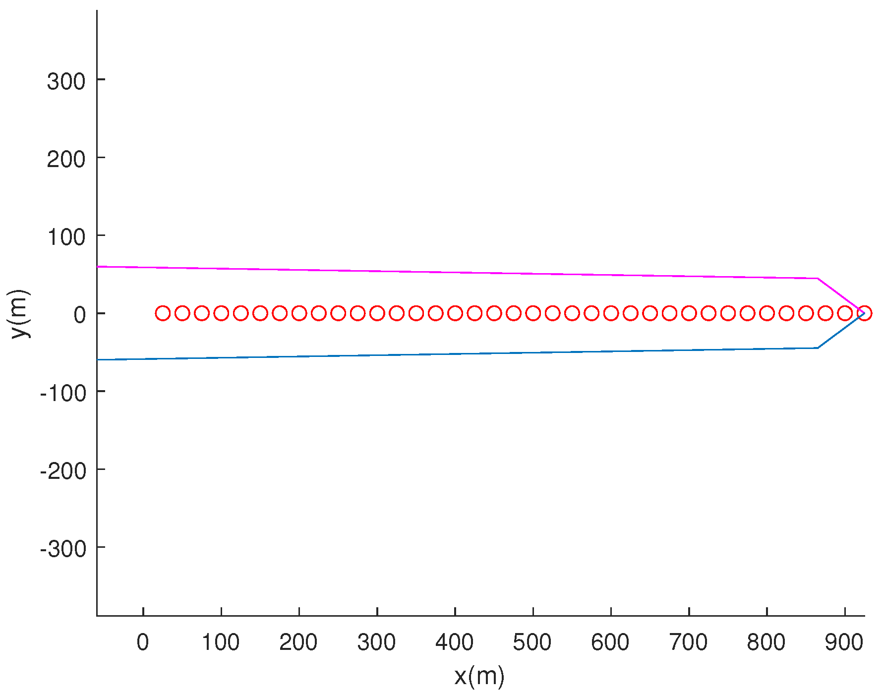
Figure 1 shows an illustration of target ship’s wake as the ship moves with a constant velocity ([5,0] in m/s) starting from the origin. Blue line segments represent the target ship’s wake to the ship’s right, and magenta line segments represent the target ship’s wake to the ship’s left. Red circles indicate the ship’s trajectory every 5 s. This ship wake model is used in MATLAB R2023a simulations (Section 4).
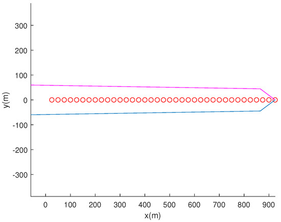
Figure 1.
An illustration of the target ship’s wake as the ship moves with a constant velocity ([5,0] in m/s) starting from the origin. Blue line segments represent the target ship’s wake to the ship’s right, and magenta line segments represent the target ship’s wake to the ship’s left. Red circles indicate the ship’s trajectory every 5 s.
The target ship’s wake to the left of the ship is termed left wake (magenta line segments in Figure 1), and the target ship’s wake to the right of the ship is termed right wake (blue line segments in Figure 1).
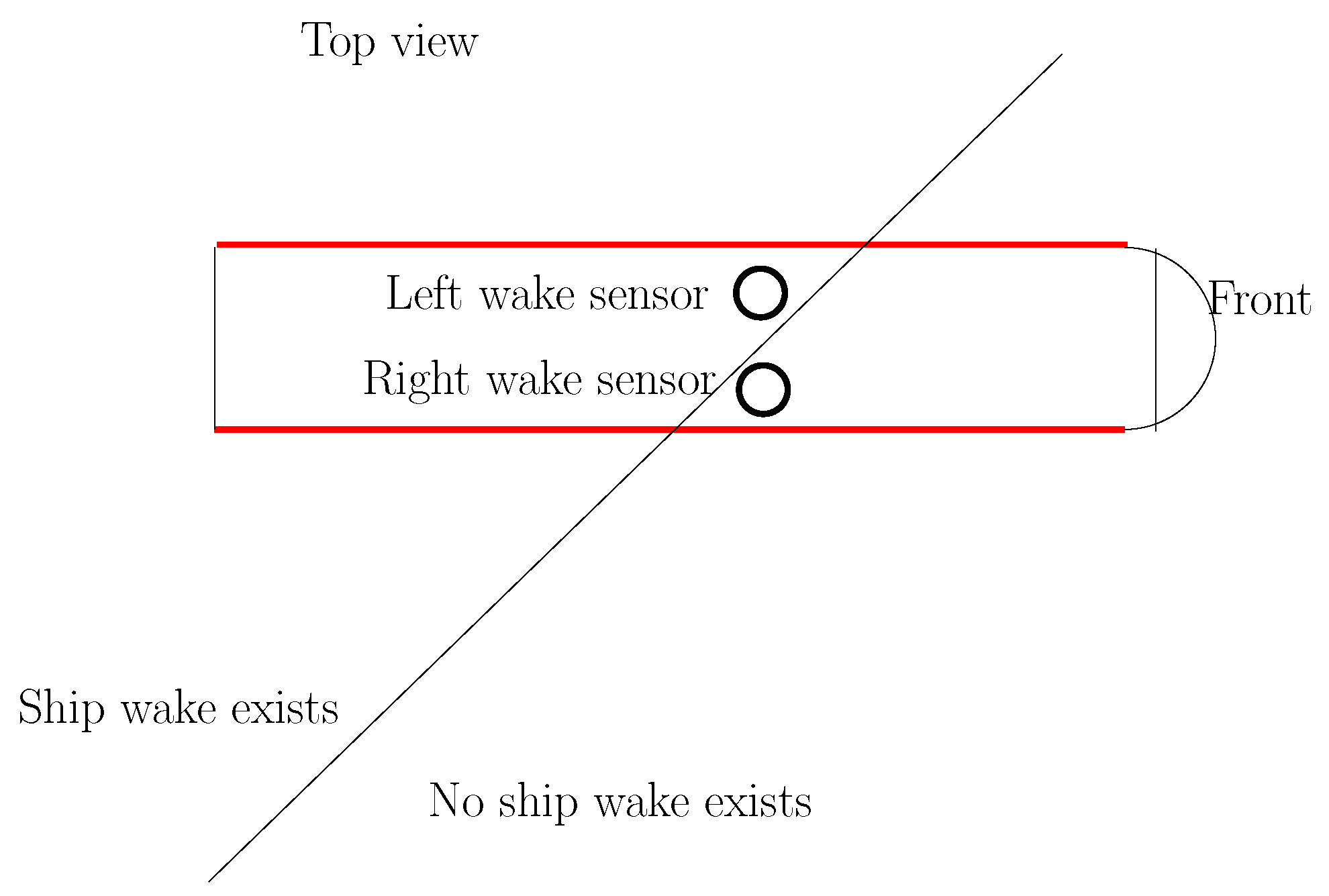
Next, we present the sensors of the AUV. Figure 2 shows the top view of the AUV. The two circles in this figure represent the two wake sensors. Note that the AUV has one wake sensor on either side. The left wake sensor exists to the left of the AUV from the top view. The right wake sensor exists to the right of the AUV from the top view.

Figure 2.
The top view of the AUV. The two circles in this figure represent the two wake sensors. In addition, the AUV has flank array sonar (bold red line segments) attached to either side. The slanted line indicates the boundary of the target ship’s wake.
In addition, the AUV has two flank array sonar (bold red line segments in Figure 2) attached to either side. The flank array sonar is used to detect the bearing angle of target sound. These sonar unites are used as passive sonar sensors for measurement of the target bearing angle.
As an example, Figure 3 illustrates the side view of the AUV. There are flank array sonars on both sides of the AUV. In Figure 3, the rectangle on the AUV’s body illustrates a flank array sonar.
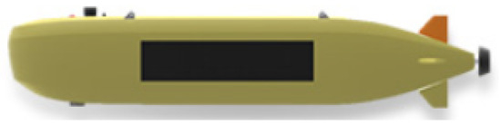
Figure 3.
An illustration of the side view of the AUV. There are flank array sonars on both sides of the AUV. In this figure, the rectangle on the AUV’s body illustrates a flank array sonar.
Section 3 presents the motion models used in this paper. Section 3.1 addresses AUV guidance controls by measuring the target ship’s bearing angle through flank array sonars. In addition, Section 3.2 addresses AUV guidance controls based on two wake sensors.
3. Motion Models
Let represent the sampling interval in discrete-time systems. Let represent the 2D position of the target ship at sample index k in the inertial reference frame. Let represent the 2D position of the AUV at sample index k in the inertial reference frame. Let represent the velocity vector of the AUV at sample index k. We say that the AUV captures the target ship as , where indicates a positive capture range. In MATLAB simulations, this study uses m.
The motion dynamics of the AUV (r) are
By changing the AUV’s rudder direction, the AUV can change its velocity vector () at sample index k. Let represent the AUV speed, which is a constant. Let represent the yaw of the AUV with respect to the x-axis in the inertial reference frame. Then, Equation (1) becomes
In practice, the angular rate of is upper-bounded by a constant, such as . This implies that
The maximum deflection of AUV fins can generate the maximum angular rate ().
The motion model of the target ship is
Here, represents the target ship’s speed, and represents the yaw of the target ship at sample index k.
3.1. AUV Guidance Control by Measuring the Target Ship’s Bearing Angle through Flank Array Sonars
Suppose that the AUV is outside the target ship’s wake and that the wake sensor cannot be used to detect the target ship’s wake. In this case, the AUV measures the target ship’s bearing angle using passive sonar sensors and heads towards the target ship.
We address AUV guidance controls by measuring the target ship’s bearing angle through flank array sonars. The yaw angle of with respect to is
where , and represents the m-th element in . In Equation (5), is the angle of the complex number .
At each sample index (k), the yaw of the AUV is controlled so that the AUV’s yaw converges to as time elapses. Let indicate the yaw error. The value of is changed so that it exists inside the interval []. Then, the following equation is applied:
If , then the AUV’s yaw is controlled with the maximum yaw rate () as follows.
where represents the sign of . Otherwise, the following is applied:
In this way, the yaw of the AUV converges to as time elapses.
Until now, we have addressed how to control the yaw of the AUV so that the AUV’s yaw converges to as time elapses. Considering uncertain AUV motion models or environmental disturbances, one can use various heading controls [15,16,17,18,19] to compute the heading control so that the AUV’s heading converges to .
3.2. AUV Guidance Controls Using Two Wake Sensors
We address AUV guidance controls using two wake sensors. As the AUV heads towards using the yaw control in Section 3.1, the AUV’s two wake sensors (one on either side) measure the target ship’s wake. This implies that the AUV enters the target ship’s wake.
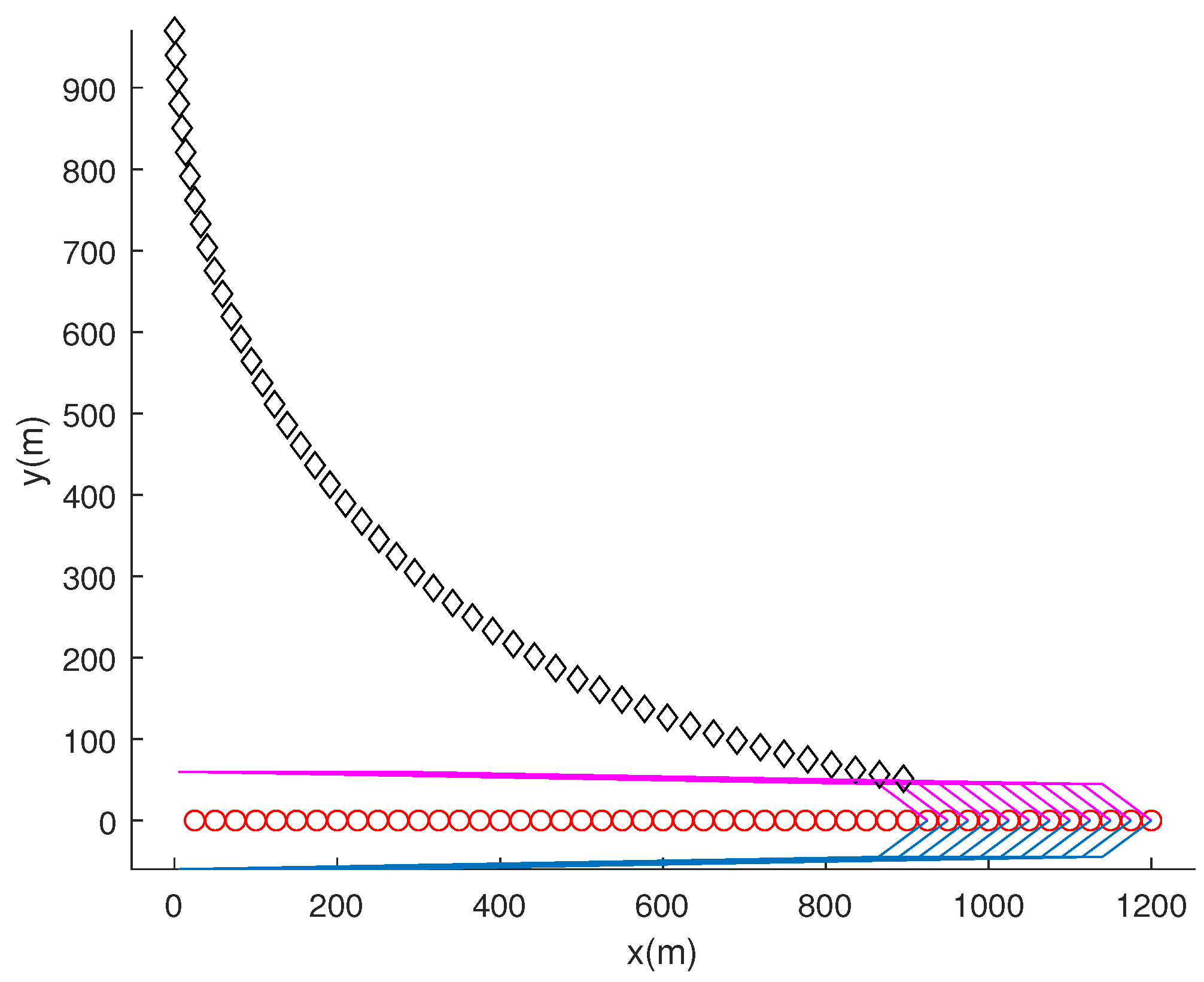
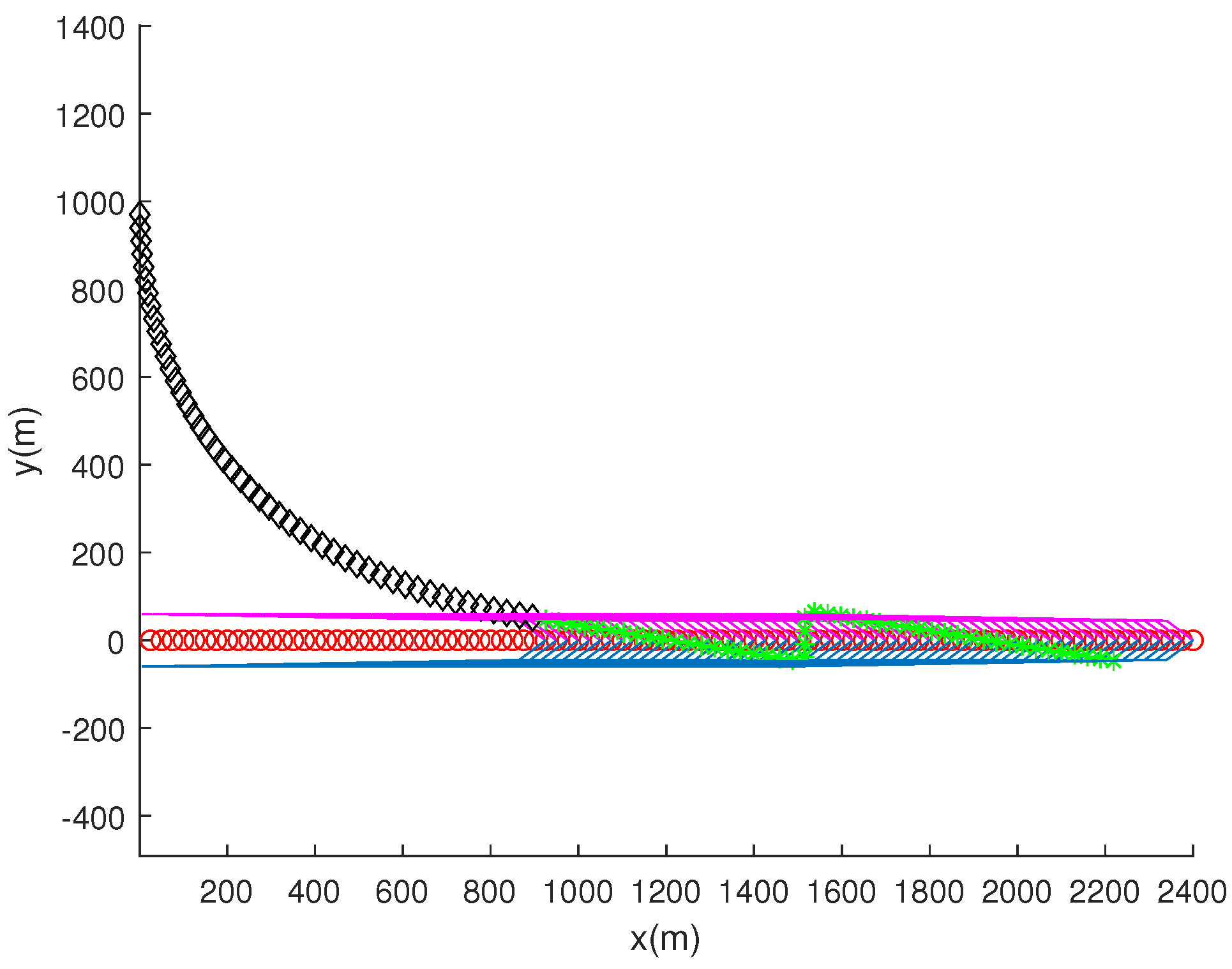
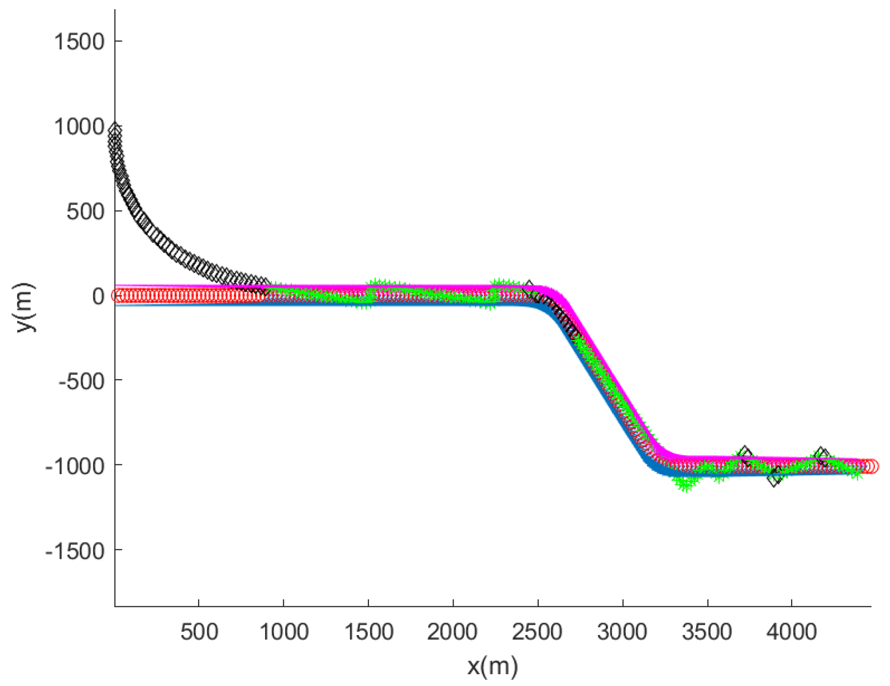
This situation is plotted in Figure 4. The AUV speed is set as m/s. In this figure, the target ship moves with a constant velocity ([5,0] in m/s) starting from the origin. Blue line segments represent the right wake, and magenta line segments represent the left wake. Red circles present the ship’s trajectory every 5 s. Black diamonds plot the AUV’s trajectory every 5 s. The AUV starts from [0,1000] in meters. Since the AUV cannot measure the target ship’s wake at sample index 0, the AUV applies the yaw control described in Section 3.1 initially.

Figure 4.
An illustration of the target ship’s wake as the ship moves with a constant velocity ([5,0] in m/s) starting from the origin. Blue line segments represent the right wake, and magenta line segments represent the left wake. Red circles indicate the ship’s trajectory every 5 s. Black diamonds depict the AUV’s trajectory every 5 s.
Suppose that the AUV enters the target ship’s wake at sample index n. Once the AUV enters the target ship’s wake, the AUV moves straight while fixing its yaw as . As time goes on, the AUV escapes the target ship’s wake. This event can be measured using two wake sensors—one on either side of the AUV. As the two wake sensors cannot measure the target ship’s wake, the AUV escapes the target ship’s wake.
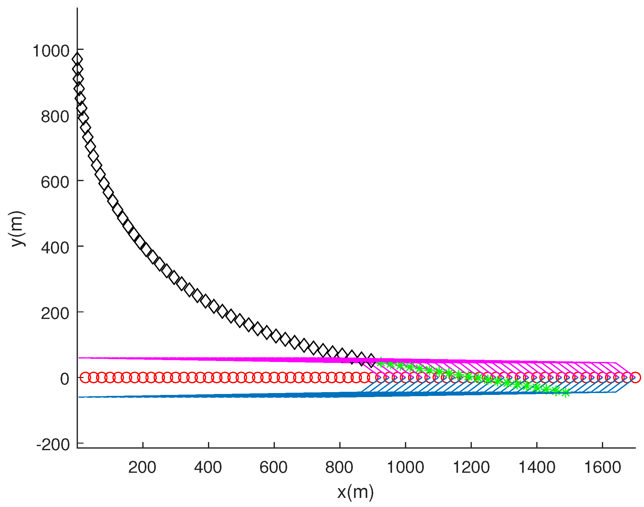
This wake-escape scenario is plotted in Figure 5. In the figure, the target ship moves with a constant velocity ([5,0] in m/s) starting from the origin. The target ship, ship wake, and AUV are plotted at every 5 s. Black diamonds represent the AUV’s trajectory as the AUV applies target bearing angle measurements. Green asterisks show the AUV’s trajectory as the AUV does not use target bearing angle measurements.

Figure 5.
An illustration of the target ship’s wake as the ship moves with a constant velocity ([5,0] in m/s) starting from the origin. Blue line segments represent the target ship’s wake to the ship’s right, and magenta line segments represent the target ship’s wake to the ship’s left. Red circles indicate the ship’s trajectory every 5 s. Black diamonds represent the AUV’s trajectory as the AUV applies target bearing angle measurements. Green asterisks show the AUV’s trajectory as the AUV does not use target bearing angle measurements. The target ship, ship wake, and AUV are plotted every 5 s. The AUV escapes the target ship’s wake by crossing the right wake. The right wake sensor loses track of ship’s wake first; then, the left wake sensor loses track of the ship’s wake later.
Figure 5 shows that the AUV escapes the target ship’s wake by crossing the right wake. The right wake sensor loses track of the ship’s wake first; then, the left wake sensor loses track of the ship’s wake later.
An illustration of the sensor configuration is presented in Figure 2. The figure depicts the moment when the AUV crosses the target ship’s wake. The slanted line shows the border of the ship’s wake. To the left of this slanted line, the target ship’s wake exists. As the AUV moves, the right wake sensor loses track of the ship’s wake first; then, the left wake sensor loses track of the ship’s wake later.
As the AUV escapes the target ship’s wake, the AUV makes a 90 degrees turn so that the AUV enters the ship’s wake again. Section 3.3 presents how to make the AUV turn 90 degrees. Using two wake sensor measurements, the AUV determines whether it will turn left or right in zig-zag maneuvers.
There can be four cases as the AUV escapes the target ship’s wake, as follows. At the moment when the AUV escapes the target ship’s wake, we apply AUV maneuver rules as follows.
- The first case is as follows: The AUV escapes the target ship’s wake by crossing the right wake. The left wake sensor loses track of the ship’s wake first; then, the right wake sensor loses track of the ship’s wake later. Then, the AUV chases the target ship using passive bearing angle measurements (Section 3.1).
- The second case is as follows: The AUV escapes the target ship’s wake by crossing the right wake. The right wake sensor loses track of the ship’s wake first; then, the left wake sensor loses track of the ship’s wake later. The AUV makes a 90-degree turn to its left until the AUV enters the right wake again.
- The third case is as follows: The AUV escapes the target ship’s wake by crossing the left wake. The right wake sensor loses track of the ship’s wake first; then, the left wake sensor loses track of the ship’s wake later. Then, the AUV chases the target ship using passive bearing angle measurements (Section 3.1).
- The fourth case is as follows: The AUV escapes the target ship’s wake by crossing the left wake. The left wake sensor loses track of the ship’s wake first; then, the right wake sensor loses track of the ship’s wake later. The AUV makes a 90-degree turn to its right until the AUV enters the left wake again.
Figure 5 corresponds to the second case in AUV maneuver rules. In the second case, the AUV makes a 90-degree turn to its left. In this way, the AUV crosses the right wake again, followed by entering the ship’s wake.
Suppose that the AUV enters the target ship’s wake at sample index n. Once the AUV enters the ship’s wake, the AUV moves straight while fixing its yaw as . As time goes on, the AUV escapes the ship’s wake. This event can be measured using two wake sensors—one on either side of the AUV. When the two wake sensors cannot measure the ship’s wake, the AUV escapes the ship’s wake.
This wake-escape scenario is plotted in Figure 6. Figure 6 corresponds to the fourth case in AUV maneuver rules. The left wake sensor loses track of the ship’s wake first; then, the right wake sensor loses track of the ship’s wake later. In the fourth case, the AUV makes a 90-degree turn to its right. In this way, the AUV crosses the left wake again, followed by entering the ship’s wake.

Figure 6.
An illustration of the ship’s wake as the ship moves with a constant velocity ([5,0] in m/s) starting from the origin. Blue line segments represent the target ship’s wake to the ship’s right, and magenta line segments represent the target ship’s wake to the ship’s left. Red circles indicate the ship’s trajectory every 5 s. Black diamonds represent the AUV’s trajectory as the AUV applies target bearing angle measurements. Green asterisks show the AUV’s trajectory as the AUV does not use target bearing angle measurements. The target ship, ship wake, and AUV are marked every 5 s. The left wake sensor loses track of the ship’s wake first; then, the right wake sensor loses track of the ship’s wake later.
Suppose that the AUV enters the ship’s wake at sample index n. Once the AUV enters the ship’s wake, the AUV moves straight while fixing its yaw as . As time goes on, the AUV escapes the ship’s wake. This event can be measured using two wake sensors—one on either side of the AUV. When the two wake sensors cannot measure the ship’s wake, the AUV escapes the ship’s wake. This wake-escape scenario is plotted in Figure 7. Figure 7 corresponds to the second case of AUV maneuver rules. The right wake sensor loses track of the ship’s wake first; then, the left wake sensor loses track of the ship’s wake later. In the second case, the AUV makes a 90-degree turn to its left. In this way, the AUV crosses the right wake again, followed by entering the ship’s wake.

Figure 7.
An illustration of the ship’s wake as the ship moves with a constant velocity ([5,0] in m/s) starting from the origin. Blue line segments represent the target ship’s wake to the ship’s right, and magenta line segments represent the target ship’s wake to the ship’s left. Red circles indicate the ship’s trajectory every 5 s. Black diamonds represent the AUV’s trajectory as the AUV applies target bearing angle measurements. Green asterisks show the AUV’s trajectory as the AUV does not use target bearing angle measurements. The target ship, ship wake, and AUV are plotted every 5 s. The right wake sensor loses track of the ship’s wake first; thereafter, the left wake sensor loses track of the ship’s wake.
So far, we have explained the second case and the fourth case of AUV maneuver rules, which can occur as the AUV escapes the ship’s wake. In these two case, a 90-degree turn can make the AUV enter the ship’s wake again.
However, the first case and the third case of AUV maneuver rules indicate that the AUV is moving against the target ship. In these two cases, the AUV chases the target ship using passive bearing angle measurements of flank array sonars (Section 3.1). Using passive bearing angle measurements, the AUV can move towards the target ship. AUV guidance controls are summarized in Algorithm 1.
| Algorithm 1 AUV guidance controls |
|
3.3. Ninety-Degree Turns of the AUV
In the second and fourth cases of AUV maneuver rules, a 90-degree turn makes the AUV enter the ship’s wake again. This subsection presents how to implement a 90-degree turn in detail.
We next present how the AUV makes a 90-degree turn to its left. Suppose that the AUV escapes the ship’s wake at sample index m. We define the goal yaw angle as
At each sample index (k), one controls the yaw of the AUV, so that it converges to as time elapses. Let indicate the yaw error. We then change so that it exists between and . We use
If , then one controls the AUV’s yaw with the maximum yaw rate () as follows.
Otherwise, one applies
In this way, the yaw of the AUV converges to as time elapses.
Next, we present how the AUV makes a 90-degree turn to its right. Instead of (9), we define the goal yaw angle as
Then, Equations (11) and (12) can be applied so that the yaw of the AUV converges to as time elapses.
So far, we have addressed how to control the yaw of the AUV so that it converges to as time elapses. Considering uncertain AUV motion models or environmental disturbances, one can use various heading controls [15,16,17,18,19] so that the AUV’s heading converges to .
4. MATLAB Simulations
The outperformance of the proposed AUV guidance is verified using MATLAB simulations. As far as we know, our paper is novel in addressing wake-responsive AUV guidance assisted by passive sonar sensors.
The computer simulation environment is as follows. As a sampling interval, this study uses . As the maximum angular rate, this study uses degrees per s. The capture range is set as m. The AUV speed is set as m/s. The target ship’s speed () in (4) is 5 m/s.
4.1. Scenario 1
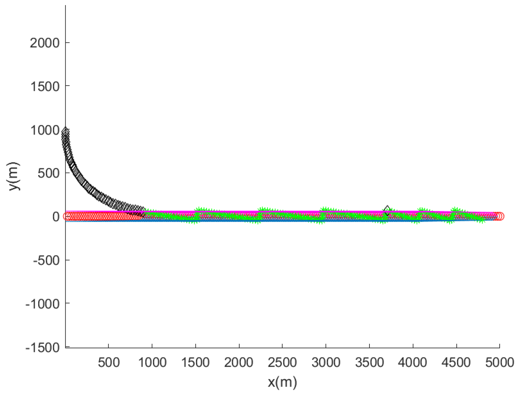
In Scenario 1, the target ship moves with a constant velocity in m/s. This target velocity is also utilized in figures in previous sections. The computer simulation ends when 1000 s elapse or the target ship is captured by the AUV.
Figure 8 shows the computer simulation result. Once the AUV meets the wake of the target ship, the AUV does not use target bearing angle measurements. Once the AUV meets the wake of the target ship, it applies two wake sensors for tracking of the target ship. Not that the AUV performs zig-zag maneuvers as it applies wake sensors for tracking of the target ship. One can argue that these zig-zag maneuvers may be desirable for avoidance the target ship’s active protection systems, such as anti-torpedo torpedoes.

Figure 8.
Scenario 1. The target ship moves with a constant velocity ([5,0] in m/s) starting from the origin. Blue line segments represent the target ship’s wake to the ship’s right, and magenta line segments represent the target ship’s wake to the ship’s left. Red circles indicate the ship’s trajectory every 5 s. Black diamonds represent the AUV’s trajectory as the AUV applies target bearing angle measurements. Green asterisks show the AUV’s trajectory as the AUV does not use target bearing angle measurements. The target ship, the wake of the target ship, and the AUV are plotted every 5 s. Black diamonds depict the AUV’s trajectory as the AUV applies target bearing angle measurements. Green asterisks depict the AUV’s trajectory when not using target bearing angle measurements.
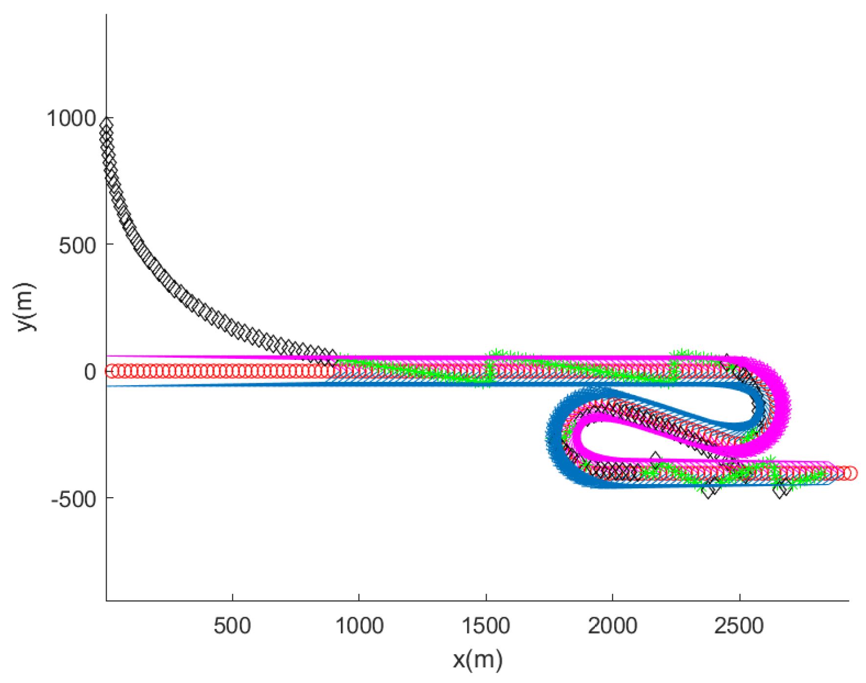
4.2. Scenario 2
Scenario 2 considers a maneuvering target ship. Initially, the target ship moves with a constant velocity in m/s. From sample index 500 to 530, the target ship maneuvers with a turn rate of degrees per second. This implies that in (4), the target’s yaw angle () is updated as
for 30 s. The computer simulation ends when 1000 s elapse or the target ship is captured by the AUV.
Figure 9 shows the computer simulation result. Once the AUV enters the wake of the target ship, the AUV applies two wake sensors for tracking of the target ship. Not that the AUV performs zig-zag maneuvers as it applies wake sensors for tracking of the target. One can argue that these zig-zag maneuvers may be desirable for avoidance of the target ship’s active protection systems, such as anti-torpedo torpedoes.
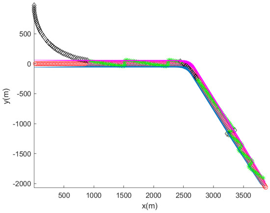
Figure 9.
Scenario 2. The maneuvering target ship, the wake of the target ship, and the AUV are plotted every 5 s. Blue line segments represent the target ship’s wake to the ship’s right, and magenta line segments represent the target ship’s wake to the ship’s left. Red circles indicate the ship’s trajectory every 5 s. Black diamonds represent the AUV’s trajectory as the AUV applies target bearing angle measurements. Green asterisks show the AUV’s trajectory as the AUV does not use target bearing angle measurements. As the target ship maneuvers, the AUV’s wake sensor loses contact with the wake of the target ship. Therefore, target bearing angle measurements are briefly utilized to track the lost target (Section 3.1).
As the target ship maneuvers, the AUV’s wake sensor loses contact with the wake of the target ship. Therefore, target bearing angle measurements are briefly used to track the lost target (Section 3.1). Note that without the assistance of bearing angle measurements, the use of wake sensors only can lead to target loss.
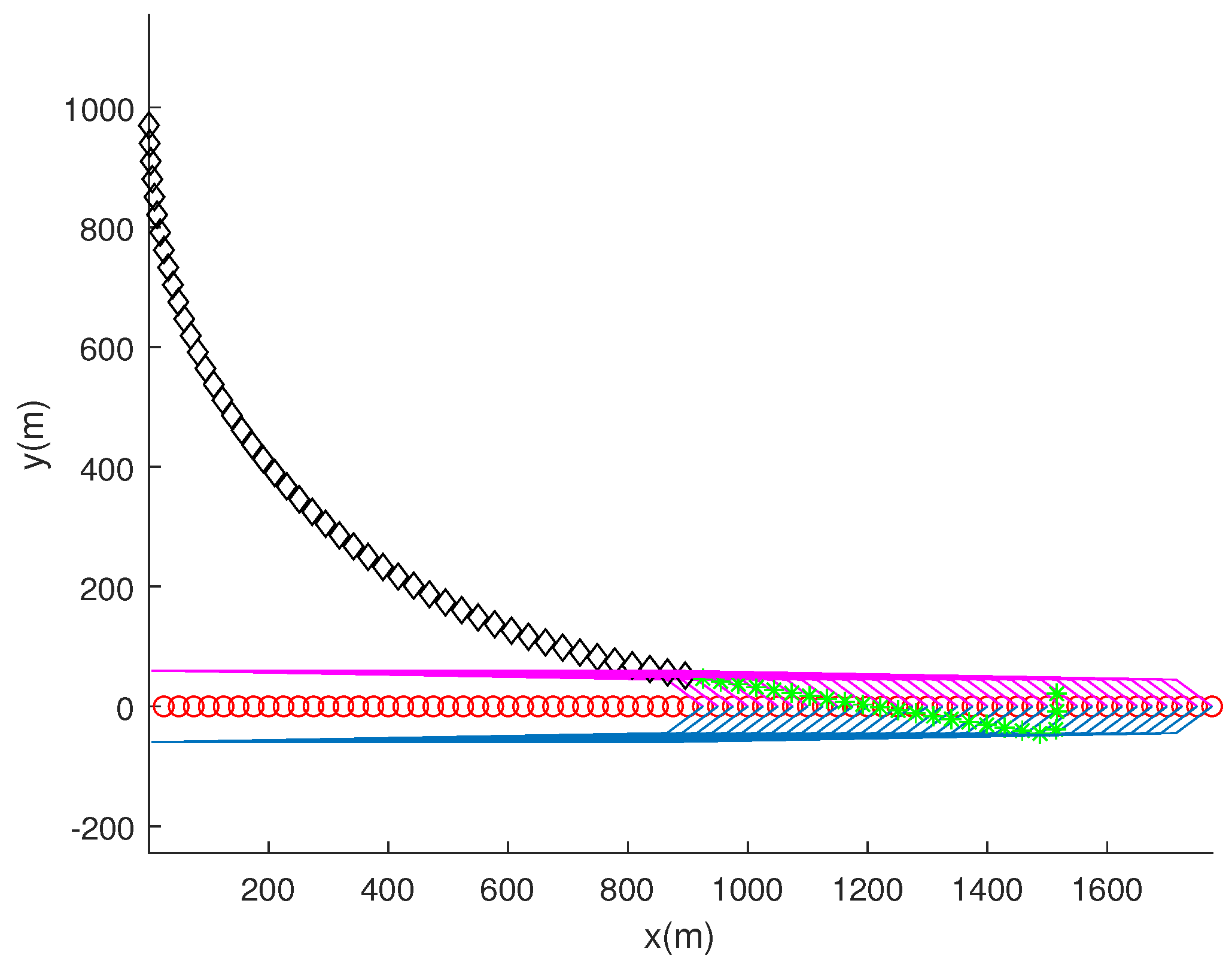
Figure 10 shows an enlarged version of Figure 9 for improved visibility. Note that as the target ship maneuvers, the AUV’s wake sensor loses contact with the wake of the target ship. Therefore, target bearing angle measurements are briefly utilized to track the lost target (Section 3.1).

Figure 10.
Scenario 2. Enlarged version of Figure 9 for improved visibility. Blue line segments represent the target ship’s wake to the ship’s right, and magenta line segments represent the target ship’s wake to the ship’s left. Red circles indicate the ship’s trajectory every 5 s. Black diamonds represent the AUV’s trajectory as the AUV applies target bearing angle measurements. Green asterisks show the AUV’s trajectory as the AUV does not use target bearing angle measurements.
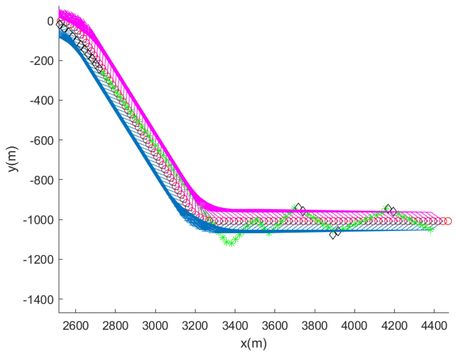
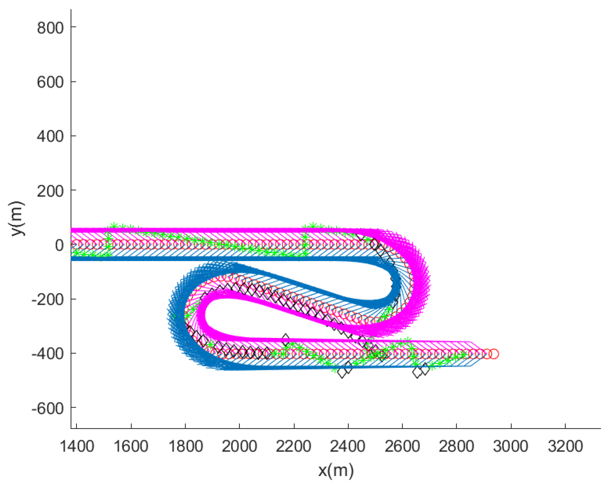
4.3. Scenario 3
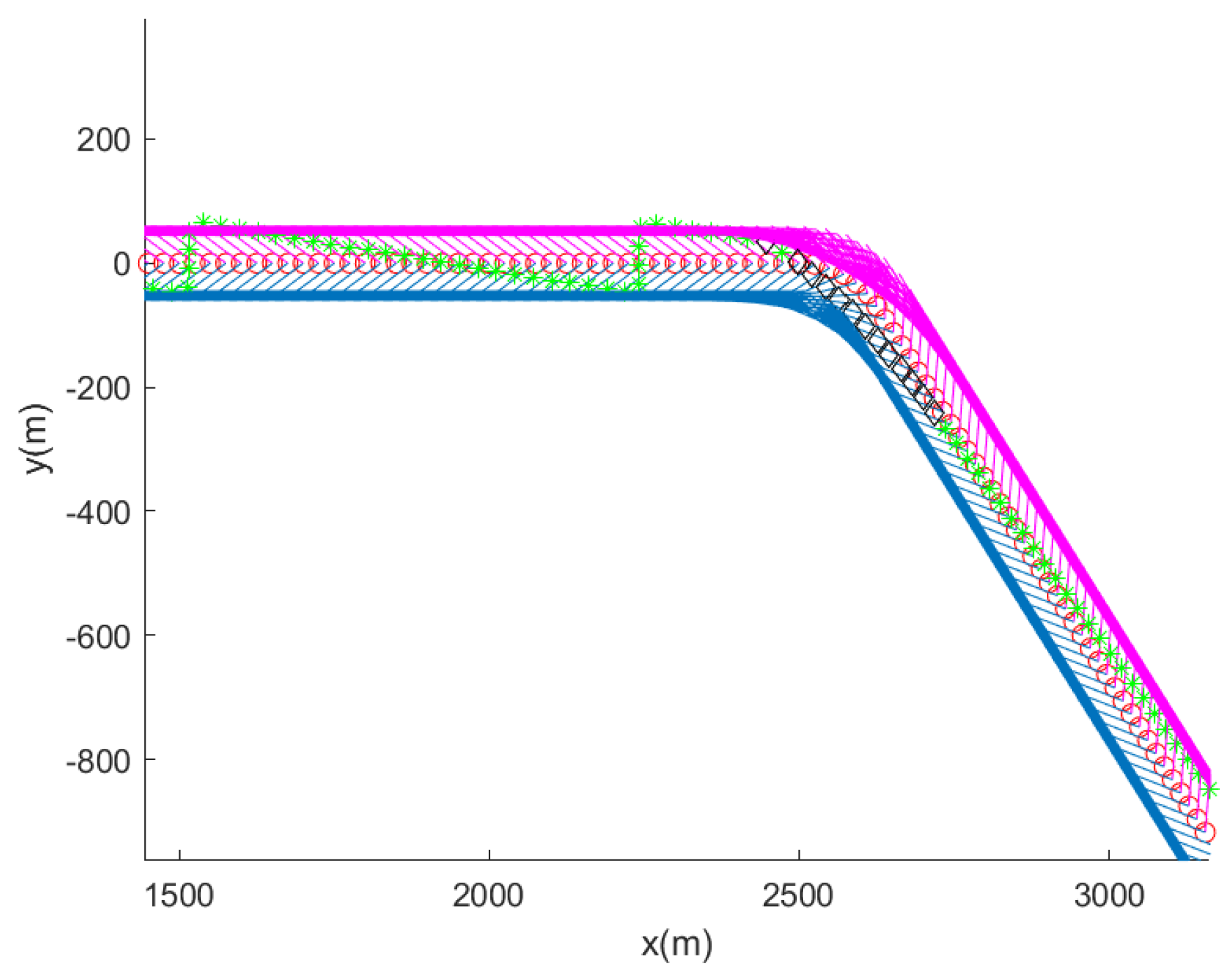
Scenario 3 considers a maneuvering target ship that changes its course two times. Initially, the target ship moves with a constant velocity in m/s. From sample index 500 to 530, the target ship maneuvers with a turn rate of degrees per second. From sample index 735 to 765, the target ship maneuvers with a turn rate of 2 degrees per second.
The computer simulation ends when 1000 s elapse or the target ship is captured by the AUV. Figure 11 shows the computer simulation result. Once the AUV enters the wake of the target ship, it applies two wake sensors for tracking of the target ship. The AUV performs zig-zag maneuvers as the AUV utilizes wake sensors for tracking of the target. One can argue that these zig-zag maneuvers may be desirable for avoidance of the target ship’s active protection systems, such as anti-torpedo torpedoes.

Figure 11.
Scenario 3. The maneuvering target ship, the wake of the target ship, and the AUV are plotted every 5 s. Blue line segments represent the target ship’s wake to the ship’s right, and magenta line segments represent the target ship’s wake to the ship’s left. Red circles indicate the ship’s trajectory every 5 s. Black diamonds represent the AUV’s trajectory as the AUV applies target bearing angle measurements. Green asterisks show the AUV’s trajectory as the AUV does not use target bearing angle measurements. After the target ship maneuvers, the AUV’s wake sensor sometimes loses contact with the wake of the target ship. Therefore, target bearing angle measurements are briefly utilized to track the lost target (Section 3.1).
After the target ship maneuvers, the AUV’s wake sensor loses contact with the wake of the target ship, and target bearing angle measurements are briefly used to track the lost target (Section 3.1). Note that without the assistance of bearing angle measurements, the use of wake sensors only can lead to target loss.
Figure 12 shows an enlarged version of Figure 11 for improved visibility. After the target ship maneuvers, the AUV’s wake sensor occasionally loses contact with the wake of the target ship. Therefore, target bearing angle measurements are briefly utilized to track the lost target (Section 3.1).

Figure 12.
Scenario 3 . Enlarged version of Figure 11 for improved visibility. Blue line segments represent the target ship’s wake to the ship’s right, and magenta line segments represent the target ship’s wake to the ship’s left. Red circles indicate the ship’s trajectory every 5 s. Black diamonds represent the AUV’s trajectory as the AUV applies target bearing angle measurements. Green asterisks show the AUV’s trajectory as the AUV does not use target bearing angle measurements.
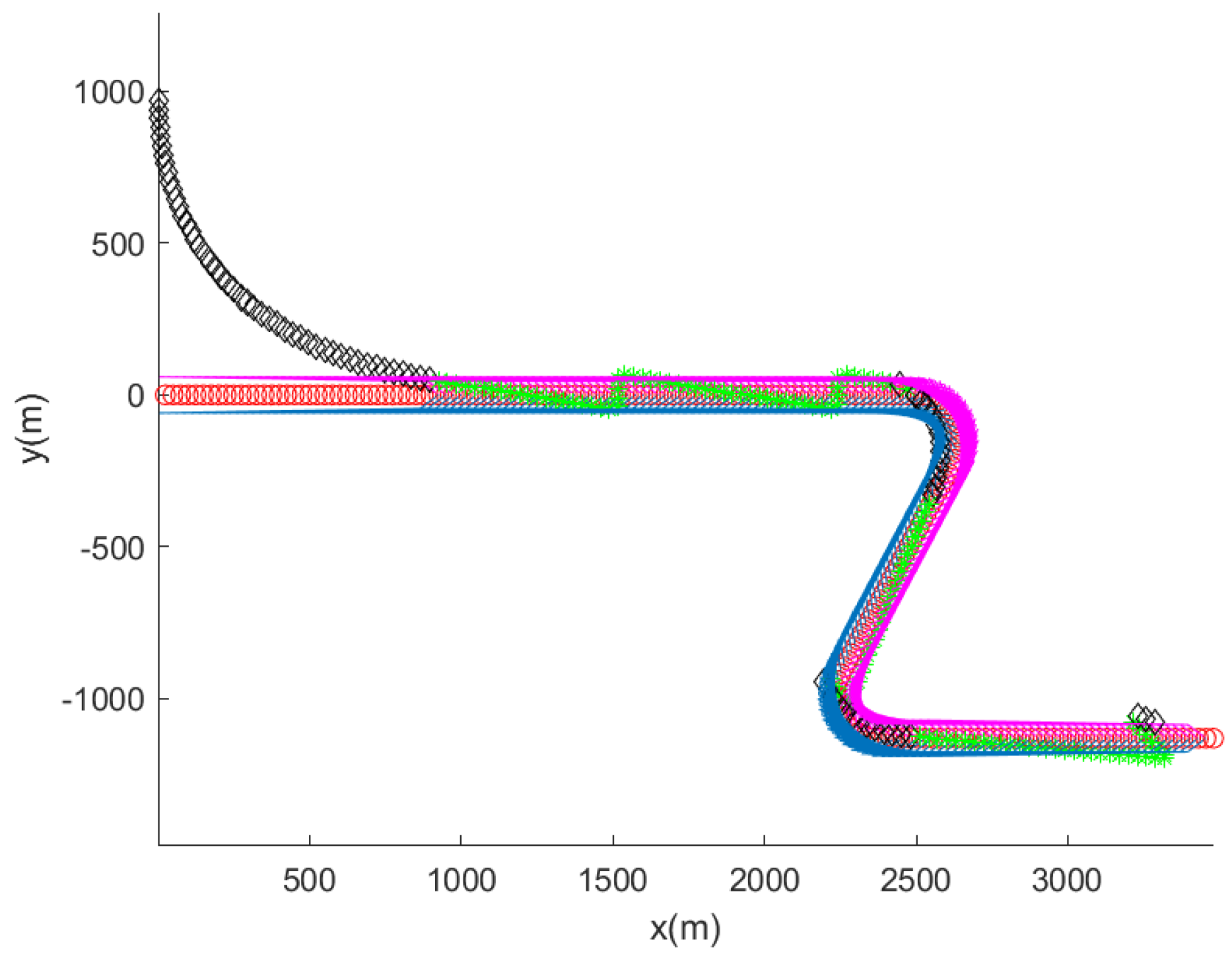
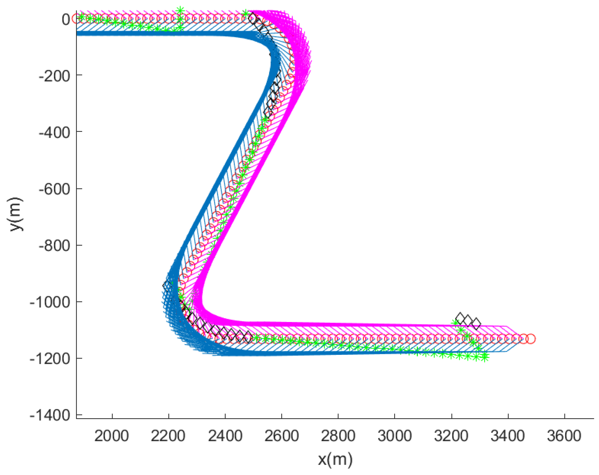
4.4. Scenario 4
Scenario 4 considers the tracking of a maneuvering target ship. Initially, the target ship moves with a constant velocity in m/s. From sample index 500 to 560, the target ship maneuvers with a turn rate of degrees per second. From sample-index 735 to 795, the target ship maneuvers with a turn rate of 2 degrees per second.
The computer simulation ends when 1000 s elapse or the target ship is captured by the AUV. Figure 13 shows the computer simulation result. Once the AUV enters the wake of the target ship, it applies two wake sensors for tracking of the target ship. The AUV performs zig-zag maneuvers as it uses wake sensors for tracking of the target. One can argue that these zig-zag maneuvers may be effective for avoiding the target ship’s active protection systems, such as anti-torpedo torpedoes.

Figure 13.
Scenario 4. The maneuvering target ship, the wake of the target ship, and the AUV are plotted every 5 s. Blue line segments represent the target ship’s wake to the ship’s right, and magenta line segments represent the target ship’s wake to the ship’s left. Red circles indicate the ship’s trajectory every 5 s. Black diamonds represent the AUV’s trajectory as the AUV applies target bearing angle measurements. Green asterisks show the AUV’s trajectory as the AUV does not use target bearing angle measurements. After the target ship maneuvers, the AUV’s wake sensor sometimes loses contact with the wake of the target ship. Therefore, target bearing angle measurements are utilized to track the lost target (Section 3.1).
After the target ship maneuvers, the AUV’s wake sensor loses contact with the wake of the target ship, and target bearing angle measurements are applied to track the lost target (Section 3.1). Without the assistance of bearing angle measurements, the use of wake sensors only can lead to target loss.
Figure 14 shows an enlarged version of Figure 13 for improved visibility. After the target ship maneuvers, the AUV’s wake sensor occasionally loses contact with the wake of the target ship. Therefore, target bearing angle measurements are utilized to track the lost target (Section 3.1).

Figure 14.
Scenario 4. Enlarged version of Figure 13 for improved visibility. Blue line segments represent the target ship’s wake to the ship’s right, and magenta line segments represent the target ship’s wake to the ship’s left. Black diamonds represent the AUV’s trajectory as the AUV applies target bearing angle measurements. Green asterisks show the AUV’s trajectory as the AUV does not use target bearing angle measurements. Red circles indicate the ship’s trajectory every 5 s.
4.5. Scenario 5
Scenario 5 considers the tracking of a maneuvering target ship. Initially, the target ship moves with a constant velocity in m/s. From sample-index 500 to 600, the target ship maneuvers with a turn rate of degrees per second. From sample index 735 to 835, the target ship maneuvers with a turn rate of 2 degrees per second.
The computer simulation ends when 1000 s elapse or the target ship is captured by the AUV. Figure 15 shows the computer simulation result. Once the AUV enters the wake of the target ship, the AUV applies two wake sensors for tracking of the target ship. The AUV performs zig-zag maneuvers as the AUV applies wake sensors for tracking of the target. One can argue that these zig-zag maneuvers may be effective for avoiding the target ship’s active protection systems, such as anti-torpedo torpedoes.

Figure 15.
Scenario 5. Blue line segments represent the target ship’s wake to the ship’s right, and magenta line segments represent the target ship’s wake to the ship’s left. Red circles indicate the ship’s trajectory every 5 s. Black diamonds represent the AUV’s trajectory as the AUV applies target bearing angle measurements. Green asterisks show the AUV’s trajectory as the AUV does not use target bearing angle measurements. The maneuvering target ship, the wake of the target ship, and the AUV are plotted every 5 s. After the target ship maneuvers, the AUV’s wake sensor sometimes loses contact with the wake of the target ship. Therefore, target bearing angle measurements are utilized to track the lost target (Section 3.1).
After the target maneuvers, the AUV’s wake sensor loses contact with the wake of the target, and target bearing angle measurements are used to track the lost target (Section 3.1). Note that without the assistance of bearing angle measurements, the use of wake sensors only can lead to target loss.
Figure 16 shows an enlarged version of Figure 15 for improved visibility. After the target ship maneuvers, the AUV’s wake sensor occasionally loses contact with the wake of the target ship. Therefore, target bearing angle measurements are utilized to track the lost target (Section 3.1).

Figure 16.
Scenario 5. Enlarged version of Figure 15 for improved visibility. Blue line segments represent the target ship’s wake to the ship’s right, and magenta line segments represent the target ship’s wake to the ship’s left. Black diamonds represent the AUV’s trajectory as the AUV applies target bearing angle measurements. Green asterisks show the AUV’s trajectory as the AUV does not use target bearing angle measurements. Red circles indicate the ship’s trajectory every 5 s.
5. Conclusions
The objective of this study is to make an AUV pursue a target ship assisted by passive sonar sensors as well as wake sensors. This scenario is applicable to making an underwater torpedo pursue a moving target ship until hitting the target.
For the tracking of a maneuvering target ship without losing the target, the AUV applies both passive sonar sensors and two wake sensors. As the wake is not detected by wake sensors and the AUV needs to search for the target ship, the AUV’s passive sonar sensors are used to detect the direction of sound generated from the target ship. To the best of our knowledge, this study is novel in addressing wake-responsive AUV guidance assisted by passive sonar sensors. The effectiveness of the proposed guidance control is verified through computer simulations. In the future, we will conduct experiments using real AUVs in order to verify the outperformance of the proposed guidance control.
Funding
This work was supported by a National Research Foundation of Korea (NRF) grant funded by the Korea government (MSIT) (Grant Number: 2022R1A2C1091682). This research was supported by the faculty research fund of Sejong University in 2023.
Institutional Review Board Statement
Not applicable.
Informed Consent Statement
Not applicable.
Data Availability Statement
Data are contained within the article.
Conflicts of Interest
The authors declare no conflicts of interest.
References
- Wang, X.Y. The guiding method through minimizing the MSE of entrance wake distance for wire-guidance plus wake-homing torpedo. In Proceedings of the 2011 IEEE International Conference on Signal Processing, Communications and Computing (ICSPCC), Xi’an, China, 14–16 September 2011; pp. 1–5. [Google Scholar]
- Cho, G.R.; Kang, H.; Kim, M.G.; Lee, M.J.; Li, J.H.; Kim, H.; Lee, H.; Lee, G. An Experimental Study on Trajectory Tracking Control of Torpedo-like AUVs Using Coupled Error Dynamics. J. Mar. Sci. Eng. 2023, 11, 1334. [Google Scholar] [CrossRef]
- Zhao, B.; Sun, J.; Zhang, D.; Zhu, K.; Jiang, H. Dynamic Analysis of Underwater Torpedo during Straight-Line Navigation. Appl. Sci. 2023, 13, 4169. [Google Scholar] [CrossRef]
- Conley, C.P.; Arthur, N. Wake Responsive Torpedo Guidance System. U.S. Patent 3049087A, 14 August 1962. [Google Scholar]
- Kim, J. A Robust Impulsive Control Strategy of Supercavitating Vehicles in Changing Systems. Appl. Sci. 2018, 8, 2355. [Google Scholar] [CrossRef]
- Liu, L.; Zhang, L.; Pan, G.; Zhang, S. Robust yaw control of autonomous underwater vehicle based on fractional-order PID controller. Ocean. Eng. 2022, 257, 111493. [Google Scholar] [CrossRef]
- Qiao, L.; Zhang, W. Trajectory Tracking Control of AUVs via Adaptive Fast Nonsingular Integral Terminal Sliding Mode Control. IEEE Trans. Ind. Inform. 2020, 16, 1248–1258. [Google Scholar] [CrossRef]
- Peng, Z.; Wang, J. Output-Feedback Path-Following Control of Autonomous Underwater Vehicles Based on an Extended State Observer and Projection Neural Networks. IEEE Trans. Syst. Man Cybern. Syst. 2018, 48, 535–544. [Google Scholar] [CrossRef]
- Tijjani, A.S.; Chemori, A.; Ali, S.A.; Creuze, V. Continuous–Discrete Observation-Based Robust Tracking Control of Underwater Vehicles: Design, Stability Analysis, and Experiments. IEEE Trans. Control. Syst. Technol. 2023, 31, 1477–1492. [Google Scholar]
- Li, Q.; Lv, Q.; Lai, H.; Xie, Z.; Wang, J. Observer-Based Adaptive Control for Trajectory Tracking of AUVs with Input Saturation. Appl. Sci. 2023, 13, 12549. [Google Scholar] [CrossRef]
- Kim, D.H.; Kim, N.; Cho, H.; Kim, S.Y. A guidance logic development for wake homing guidance system (ICCAS 2014). In Proceedings of the 2014 14th International Conference on Control, Automation and Systems (ICCAS 2014), Gyeonggi-do, Republic of Korea, 22–25 October 2014; pp. 190–194. [Google Scholar]
- Liang, Q.; Luo, M.; Wang, Y.; Hao, X. Multi-attacks effectiveness evaluation of UUV based on wake guidance. Ocean Eng. 2022, 266, 112654. [Google Scholar] [CrossRef]
- Khan, R.S. A Simple Model of Ship Wakes. Master’s Thesis, The University of British Columbia, Vancouver, BC, Canada, 1994. [Google Scholar]
- Teng, Y.; Fan, W. A Bubble Distribution Model in Remote Ship Wake Construction and Simulation. In Proceedings of the 2015 5th International Conference on Instrumentation and Measurement, Computer, Communication and Control (IMCCC), Qinhuangdao, China, 18–20 September 2015; pp. 1734–1737. [Google Scholar]
- Zhou, X.; Chen, F. Feedback Heading Control for Autonomous Underwater Vehicle Based on Reduced-Order Observer. In Proceedings of the Advances in Wireless Communications and Applications; Kountchev, R., Mahanti, A., Chong, S., Patnaik, S., Favorskaya, M., Eds.; Springer: Singapore, 2021; pp. 47–54. [Google Scholar]
- Luo, Y.-S.; Wen, X.-P.; Li, S.W. H∞ Heading Control of AUV Based on State Observers. In Proceedings of the Future Control and Automation; Springer: Berlin/Heidelberg, Germany, 2012; pp. 165–174. [Google Scholar]
- Guo, R.; Chen, Y.; Liu, G.; Wang, G.; Xu, G. Heading Control of Autonomous Underwater Vehicle Based on Sliding Mode Control. In Proceedings of the 27th International Ocean and Polar Engineering Conference, San Francisco, CA, USA, 25–30 June 2017. [Google Scholar]
- Wang, D.; Shen, Y.; Wan, J.; Sha, Q.; Li, G.; Chen, G.; He, B. Sliding mode heading control for AUV based on continuous hybrid model-free and model-based reinforcement learning. Appl. Ocean. Res. 2022, 118, 102960. [Google Scholar] [CrossRef]
- Li, D.; Du, L. AUV Trajectory Tracking Models and Control Strategies: A Review. J. Mar. Sci. Eng. 2021, 9, 1020. [Google Scholar] [CrossRef]


Disclaimer/Publisher’s Note: The statements, opinions and data contained in all publications are solely those of the individual author(s) and contributor(s) and not of MDPI and/or the editor(s). MDPI and/or the editor(s) disclaim responsibility for any injury to people or property resulting from any ideas, methods, instructions or products referred to in the content. |
© 2024 by the author. Licensee MDPI, Basel, Switzerland. This article is an open access article distributed under the terms and conditions of the Creative Commons Attribution (CC BY) license (https://creativecommons.org/licenses/by/4.0/).