1. Introduction
Forming steel plates with complex curvature is a critical step in the ship fabrication process. According to the plate-and-shell theory, the plate undergoes shape change due to in-plane and out-of-plane strain generated within the plate. Therefore, forming is the process of inputting the combinations of in-plane and out-of-plane strain into the plate [
1]. To satisfy the strain combination requirements of forming, thermal and mechanical processing are frequently alternated in engineering practice [
2]. However, switching machining platforms is counterproductive to automation as it adds to the overall complexity of the forming process. The integrated heating and mechanical rolling forming (IHMRF) process was recently introduced for efficiently manufacturing complex curvature hull plates [
3]. It combines the advantages of heating and mechanical roll forming by integrating thermal and mechanical loads in one work platform. Integrating thermal and mechanical loads avoids platform switching and facilitates the development of automated systems. In addition, coupling thermal and mechanical loads enriches the available in-plane and out-of-plane strain combinations.
In IHMRF, the plate is simultaneously subjected to the mechanical bending force of the rollers and the heating action of the heat source, also known as thermo-mechanical loads. When the thermo-mechanical loads applied to the plate cause the stresses in the plate to reach the yield point, plastic deformation will occur at the loading location and its immediate vicinity. Localized plastic deformation will extend along the loading path due to the movement of thermo-mechanical loads along the loading path. The target shape is achieved by controlling the local deformation. This mode of forming is usually referred to as line loading. In order to form the target shape, the process planning needs to be developed first, including determining the magnitude of the thermo-mechanical loads and the arrangement of the loading paths. However, IHMRF is a non-die process, and the relationship between the loading and deformation is complex. As a result, numerous iterative simulations are typically required to identify the ideal planning, which invariably requires a significant number of plate deformation predictions. Therefore, accurate and efficient deformation prediction of deformation in hull plate manufactured through the IHMRF process is essential for developing the process planning and ensuring the quality of the components.
The advantage of the thermo-elastic–plastic finite element method is that it can accurately simulate both the transient and final states of the mechanical behavior by considering all the variables that affect the deformation during the line-loading process [
4]. Because of its great accuracy, the method can validate other simplified methods or analyze the mechanisms of the forming process [
5]. However, because of the nonlinearities in the TEP-FE analysis of the IHMRF process, such as load movement and temperature-dependent material properties, simulating a single-line-loading process with this method takes a long time. Furthermore, the deformation prediction time for the TEP-FEM becomes even more redundant because numerous loading paths are typically included in the IHMRF process. Despite simplifying the loading model of the TEP-FEM, the computational time consumption remains too high [
5]. Therefore, for process planning, the TEP-FEM is not a suitable method for predicting plate deformation. For the process planning of the IHMRF process, a more efficient deformation prediction method must be developed while maintaining computational accuracy.
In contrast, the inherent strain method (ISM) is a simplified method that aims to improve the efficiency of deformation prediction. It obtains the deformation of the workpiece through an elastic analysis with the inherent strain as the load [
6]. The inherent strain method was originally proposed to predict the residual deformation of the workpiece during metal welding. In welding, the distribution of residual plastic strain in the workpiece tends to be approximately constant in the middle region of the loading path and is geometrically insensitive [
7]. Residual plastic strain represents the inherent effect of the machining process and is often referred to as inherent strain. Experiments or TEP-FE simulations on relatively tiny specimens can be used to derive the inherent strain because its distribution tends to be constant [
8]. The computing efficiency is significantly increased by mapping the inherent strain under the same process conditions onto large-scale structures for elastic deformation field analysis. Recently, researchers have found that the distribution of residual plastic strain in machined parts also tends to be constant during line-loading processes including local line rolling, additive manufacturing, and line heating [
9,
10,
11,
12]. As a result, the ISM has advanced further and is now being applied to predicting deformation in more complex line-loading processes. Nevertheless, research on the use of the ISM for the IHMRF process is lacking.
As mentioned above, the application of the ISM is based on the fact that inherent strain distributions tend to be constant. Therefore, it is necessary, first, to analyze the characteristics of the inherent strain distribution of the IHMRF process. Another problem is that the arrangement of the loading paths for the IHMRF process is more complex than welding. On the one hand, the arrangement of the loading paths is possible at certain positions on the plate, for example, close to the edge of the plate. The inherent strains may differ due to the constraints of the surrounding material at different locations on the plate. Results may be inconsistent if the inherent strain at one place is applied to other areas. Nonetheless, it will undoubtedly take a long time to determine the inherent strain depending on the position of each loading path. Therefore, it is necessary to discuss the effect of the proximity of the loading path to the edge of the plate on the inherent strain and, thus, to determine a reasonable method for obtaining the inherent strain.
On the other hand, loading paths may cross or be close to each other. The previous and subsequent paths may interact because of residual stress. Existing ISMs do not adequately consider the effects of residual stresses during sequential loading. Therefore, there is a need to clarify these effects and then consider them in the ISM to improve accuracy.
This paper proposes a multipath process-based inherent strain method (MPISM) for efficiently predicting plate deformation by the IHMRF process. It is difficult to measure and observe the inherent strain using experimental methods because of the high-temperature and mechanical-loading conditions of the IHMRF process. As a result, the primary tool used in this study was the experimentally verified TEP-FEM. The distribution characteristics of the inherent strains of the IHMRF process were analyzed, thus clarifying the feasibility of developing an efficient prediction method based on the basic concepts of the ISM. The effects of the proximity of the processing paths to the plate edges and the crossing or proximity between the processing paths on the inherent strain were analyzed, thus giving a method for taking these effects into account.
3. TEP-FE Analysis of the IHMRF Process
Before the MPISM is presented, the IHMRF process is first simulated by the TEP-FEM. The general characteristics of the inherent strain distribution of the plate in the IHMRF process were clarified based on the TEP-FEM results. In addition, the effects of the proximity of the loading paths to the plate edges and the intersection or proximity of the loading paths to each other on the inherent strain during the IHMRF process were analyzed.
3.1. TEP-FEM and Experimental Validation
The TEP-FE analysis of the IHMRF process was performed based on ABAQUS software. Due to the negligible influence of mechanical processes on thermal effects in IHMRF, a decoupled thermo-mechanical analysis scheme was adopted. However, the contribution of the transient temperature field to the stresses through thermal expansion was considered. The solution procedure consisted of two steps. Firstly, the temperature history of induction heating was obtained by heat transfer analysis. Thermal radiation and convective heat transfer boundary conditions were considered in the heat transfer analysis. The surface heat source model was used to simulate the induced heat source. Then, the temperature history and mechanical action of the rollers were applied to analyze the mechanical response of the plate. In the mechanical analysis, the mechanical action of the rollers is modeled through equivalent displacement loads. To prevent rigid displacements, a spring constraint is used.
The same mesh with a size of 10 mm × 10 mm was used in heat transfer and mechanical analyses. The ABAQUS element S4R was used for mechanical analyses, and the element DS4 was used for heat transfer analyses. The Mises yield criterion was used to characterize the yielding behavior of the material. The temperature-dependent thermo-physical and mechanical properties were considered in the decoupled analysis.
The experimental validation of the TEP-FEM guarantees the dependability of the outcomes.
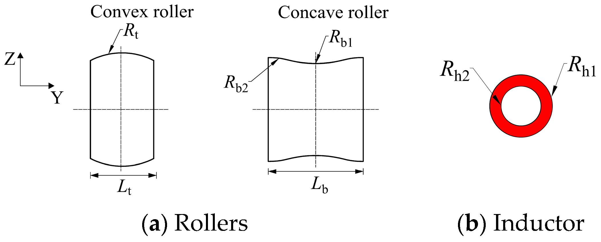
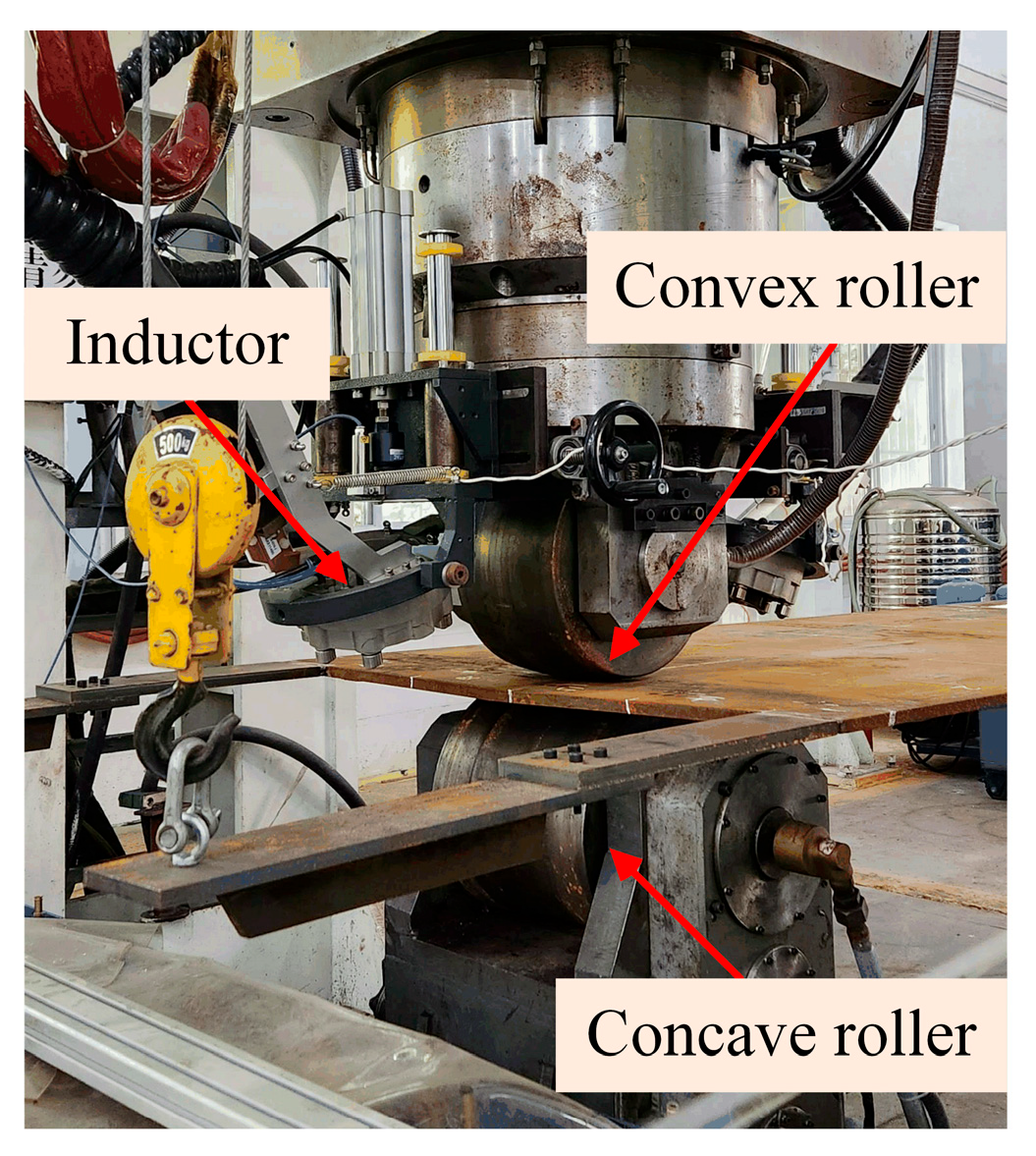
Figure 2 shows a photograph of the experimental setup. It mainly consists of a control system, a three-axis gantry robot, a heating–rolling unit, a water-jet launch device, and a 3D scanner measurement unit. The geometry and dimensions of the rollers and the induction heat source are shown in
Figure 3 and
Table 1. Since the main focus of this study was on the ISM, only a brief description of the TEP-FEM validation procedure is provided here, and more information is available in reference [
5].
3.2. General Characteristics of the Inherent Strain Distribution
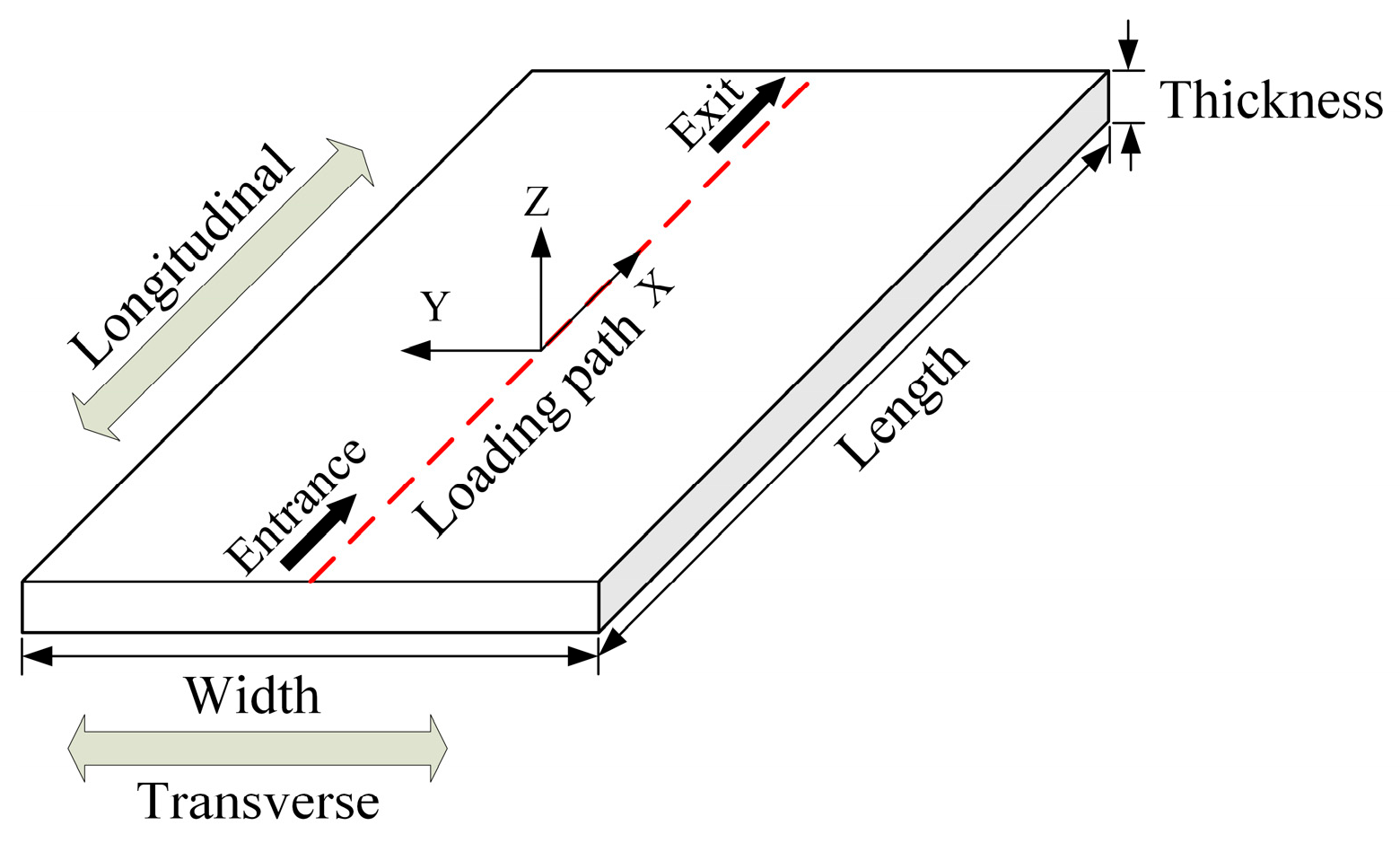
As shown in
Figure 4, the loading path was the center line in the length direction of the plate. The material of the plate is mild steel Q235, and its geometric dimensions are 1600 mm × 1000 mm × 16 mm. The TEP-FE analysis utilized values for plate thickness
h ranging from 15 to 35 mm, forming depth
d between 2 and 6 mm, heat source power
P between 20 and 40 kW, and plate movement velocity
v between 2 and 6 mm/s. Directions parallel to the loading path are classified as longitudinal, and directions perpendicular to the path are transverse.
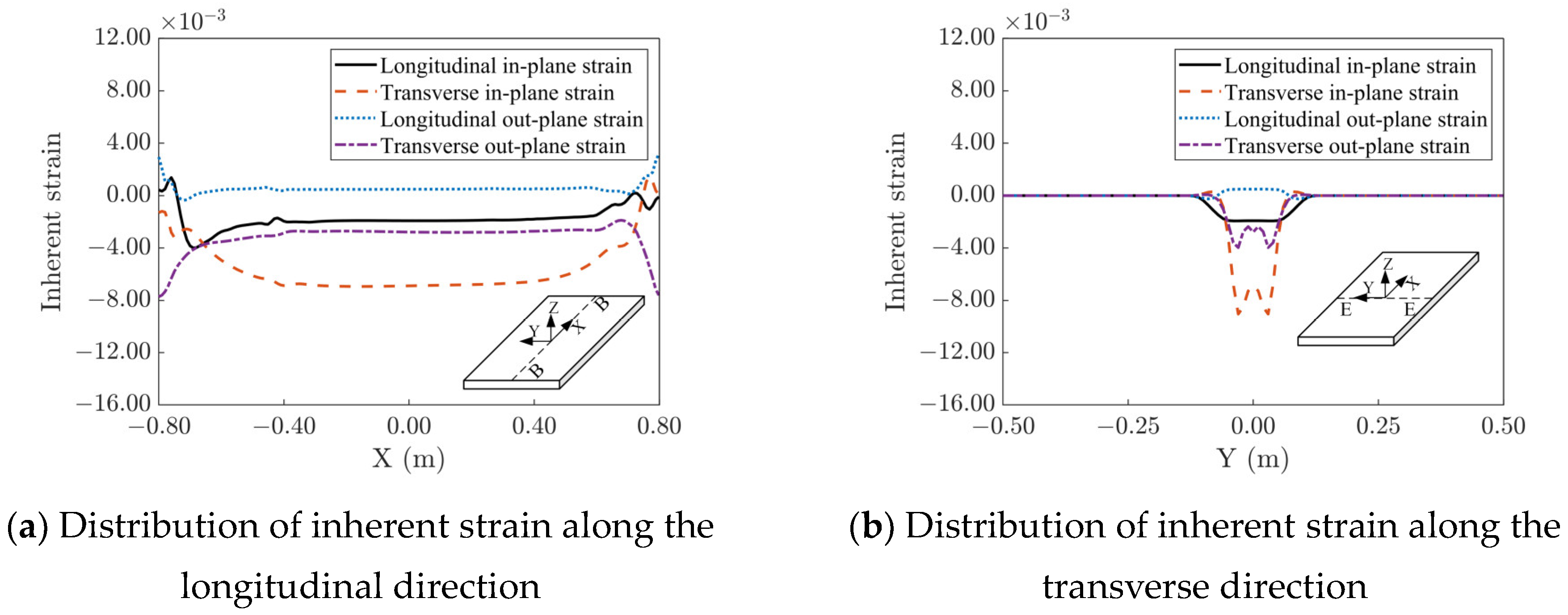
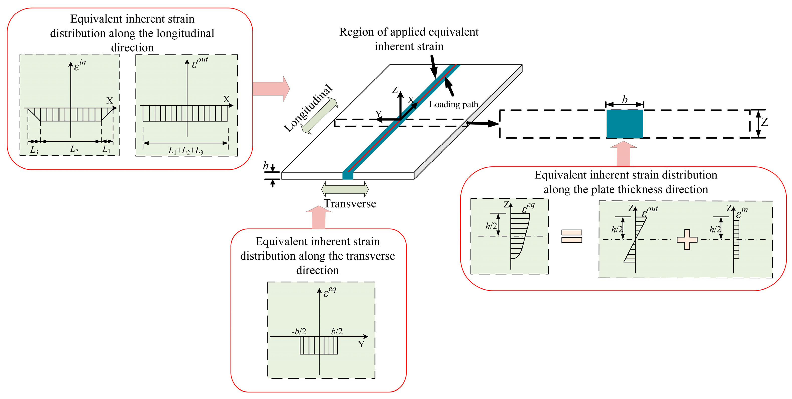
Figure 5 illustrates the inherent strain distribution curve of the plate during the IHMRF process. As shown in
Figure 5a, the inherent strain varied significantly only near the beginning and end of the loading path, while it remained essentially constant in the middle region. This is because the loads and constraints acting on the material in the middle parts of the loading path were almost identical, resulting in highly similar strains in these areas. However, there were significant temperature and constraint variations near the beginning and end of the loaded loading path and the inherent strain changed correspondingly. As shown in
Figure 5b, the values of the inherent strains were relatively complex along the transverse direction, but their larger values were concentrated in the geometrical scale range of the heat source. It should be emphasized that
Figure 5 shows the general characteristics of the inherent strain distribution. The inherent strains generated by different process parameters are similar to those in
Figure 5, except that the magnitude of the strains may vary. According to the distribution characteristics of inherent strains, it is feasible to develop an efficient prediction method for plate deformation during the IHMRF process based on the basic concepts of the ISM.
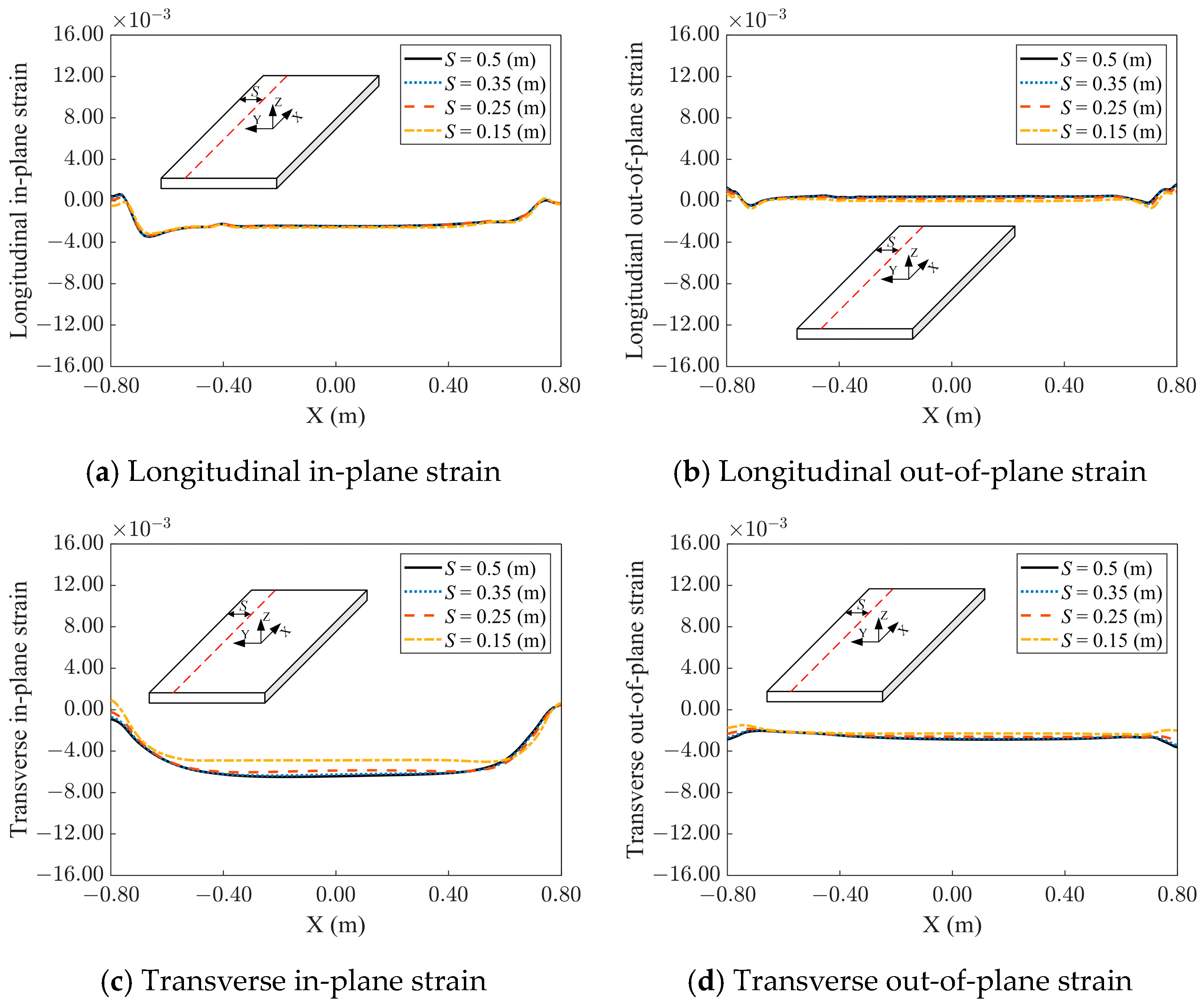
3.3. The Effect of Loading Paths near the Plate Edge
It is typical to arrange the loading path at various distances from the plate edge during forming. IHMRF loading occurs locally, with deformation centered around the loading path. Consequently, the material away from the loading route acts as a constraint on the line-loading-induced deformation. The strength of the constraint depends on the loading position. Because of symmetry, constraints are the same on both sides of the loading path when it is in the center of the plate. However, the constraints on the side that favors the plate edge may lessen as the loading path approaches one of the plate edges. This means the inherent strain will vary when loading at different positions.
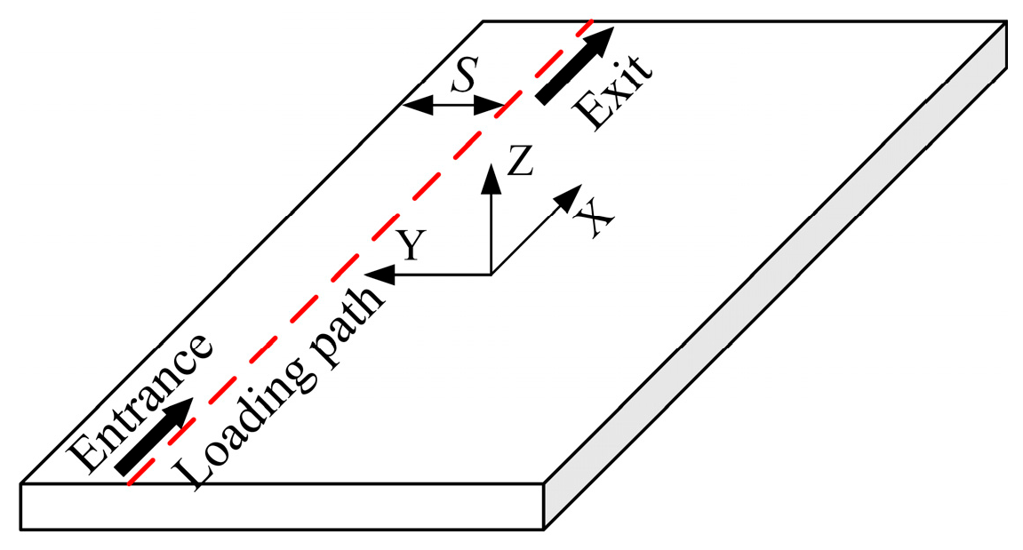
TEP-FE analyses were performed to examine the effect of the loading path near the plate edge on the inherent strain. A line parallel to the plate edge was chosen as the loading line, as seen in
Figure 6, and its distances from the plate edge,
S, were set at 150 mm, 250 mm, 350 mm, and 500 mm, in that order. The minimal value of
S was determined to be 150 mm based on the typical width of rollers used in the IHMRF process. The plate dimensions and loading characteristics remained unchanged from
Section 3.2.
The strain distributions under various loading parameters were very similar. The results under one set of loading parameters are analyzed in detail here as an example. The distribution of inherent strains that resulted from varying
S values is displayed in
Figure 7. The transverse out-of-plane strain, longitudinal out-of-plane strain, longitudinal out-of-plane strain, and longitudinal in-plane strain produced at various distance conditions were all similar. On the other hand, the transverse in-plane strain remained constant for the remaining distance conditions and only reduced at
S = 150 mm. These findings demonstrate that the distance between the loading path and the plate edge had a negligible impact on the inherent strain within a concise range.
3.4. Effect of Multiple Loading Paths
- (1)
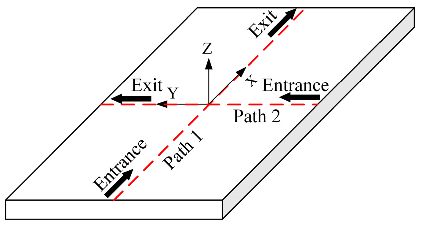
Effects of loading path crossing
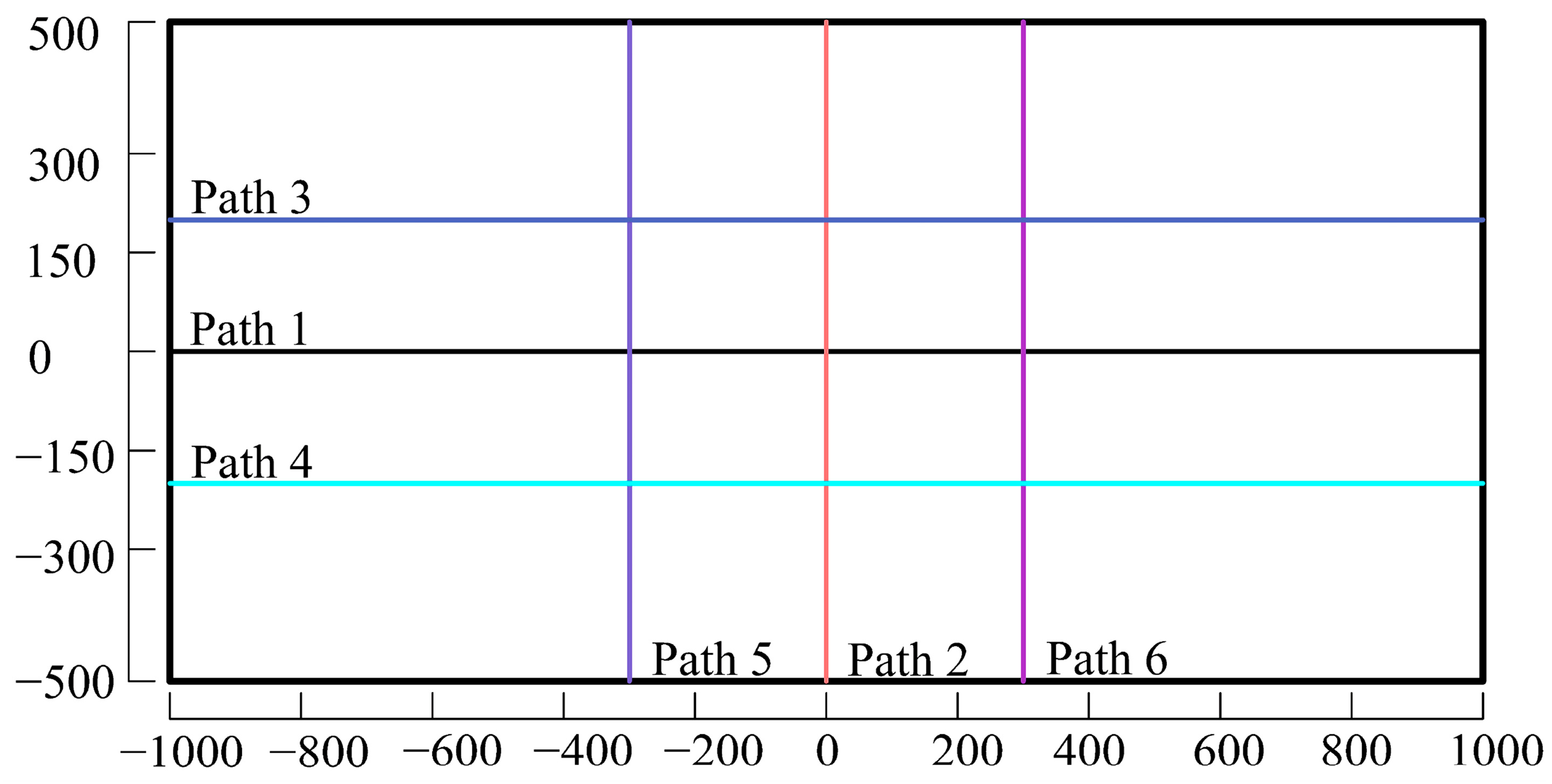
TEP-FE analyses were performed to examine the effect of loading path crossing on the inherent strain. As illustrated in
Figure 8, the two loading lines were set to be perpendicular to each other. After completing Path 1 and letting the plate cool to room temperature, Path 2 was carried out. The material characteristics, plate dimensions, and loading parameters were maintained as in
Section 3.2.
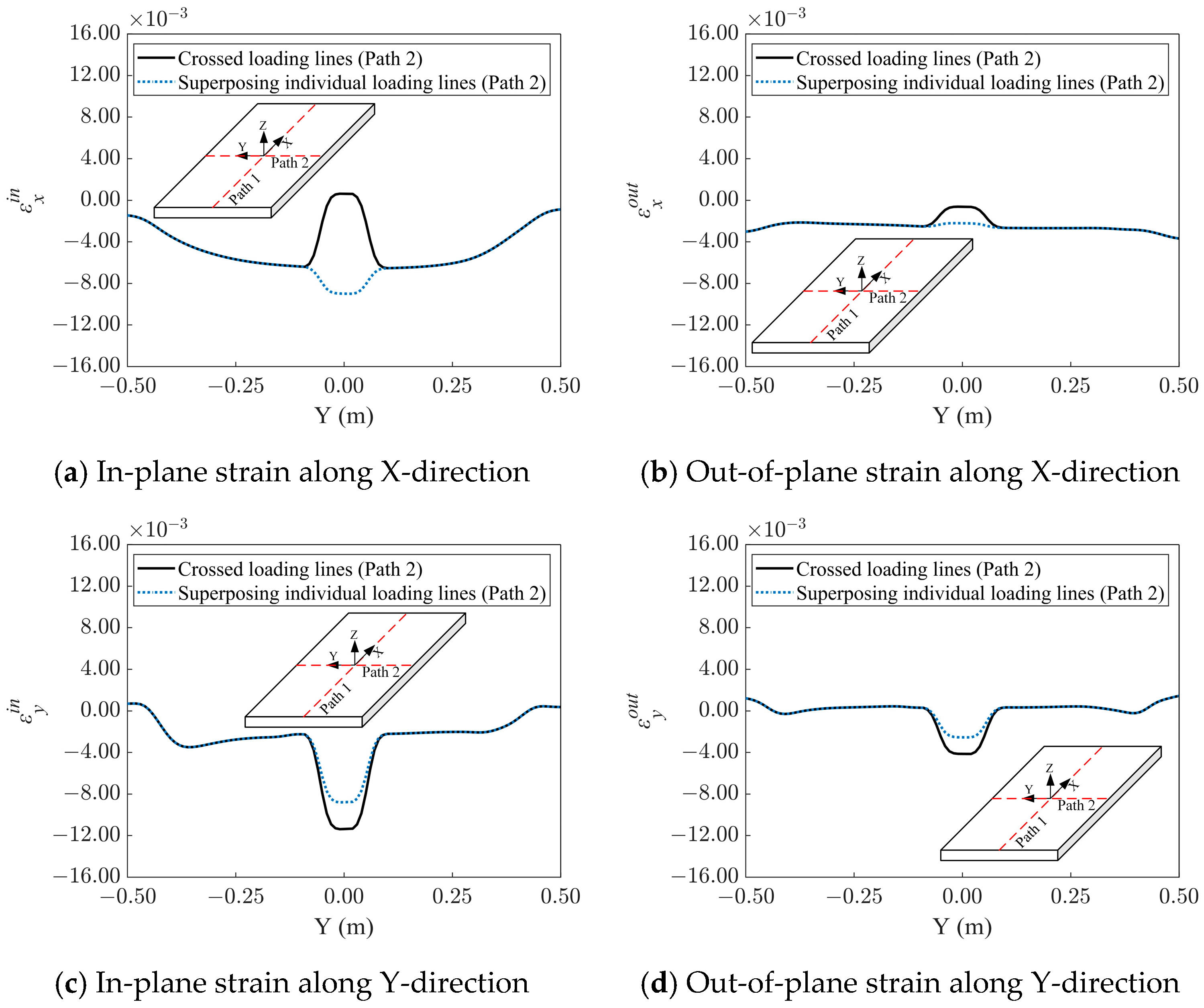
The strain distributions under various loading parameters were very similar. The results under one set of loading parameters are analyzed in detail here as an example. The inherent strain distribution along Path 2, as determined by the single-line-loading linear superposition and the cross-loading line TEP-FE analysis, is depicted in
Figure 9. The strain distribution of the cross-loaded line in the middle of Path 2 (in
Figure 8) differed significantly from the linear superposition of the single-line loading, which happened to be the intersection of the loading line. This indicates that the effect of the cross-loaded line on the strain distribution was primarily concentrated in the vicinity of the intersection point, with the difference between the two paths being smaller in the area beyond the intersection point. Similar results were obtained for Path 1. The difference between the single-line loading linear superposition and the cross-processing approach is primarily associated with the residual stress distribution [
13]. In the middle region, Path 1 completion resulted in a substantial
x-direction tensile residual stress, whereas the
y-direction residual stress was modest. Because the residual stresses were mostly concentrated in this region, the scale range of the strain-affected region was nearly equal to the diameter of the induction heating source used in the analyzed example. As seen in
Figure 9b–d, the magnitude of the remaining strain components was more akin to that of a single-loaded linear superposition.
- (2)
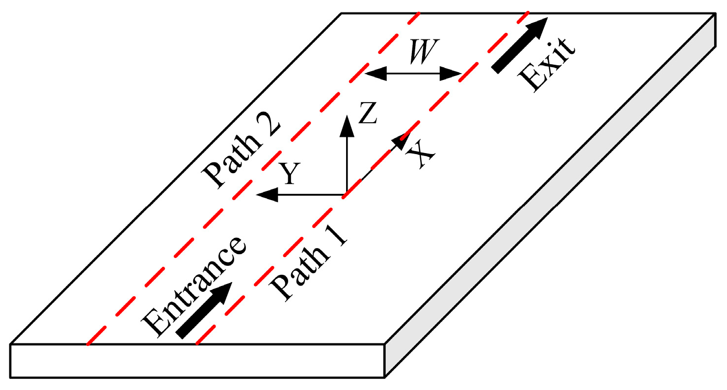
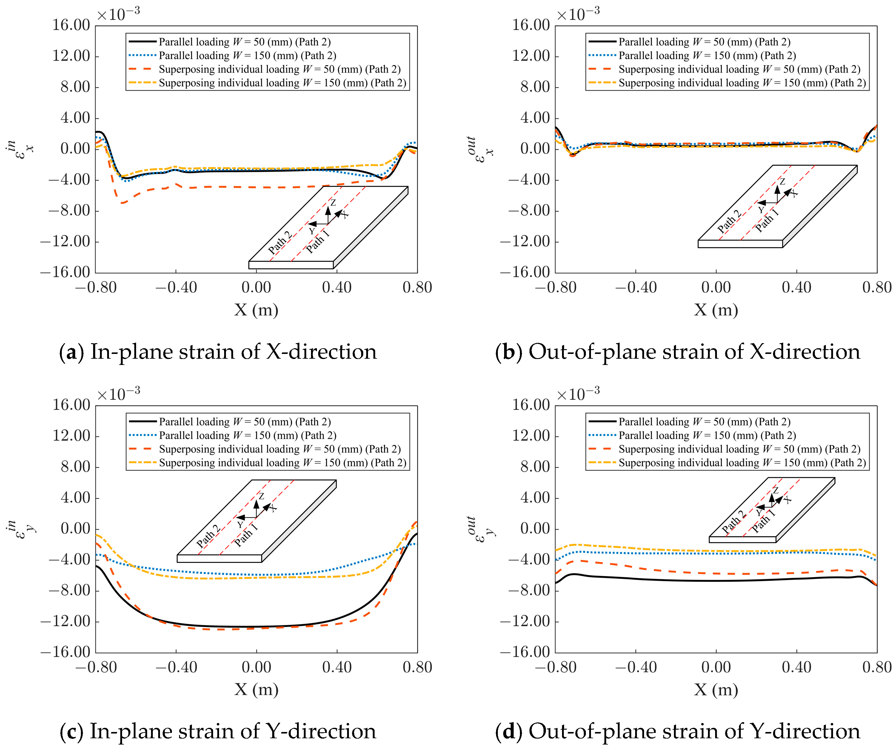
Effect of loading path spacing
In order to analyze the effect of loading path spacing, TEP-FE analyses with two loading paths parallel to each other, as shown in
Figure 10, were carried out. In general, as the distance between the two loading paths increased, the overlap area of the plastic zone md, and the interaction between the two loading paths decreased accordingly. In the analyzed example, the values of the loading path spacing
W were chosen to be 50 mm and 150 mm, which was selected considering the diameter of a typical induction heating source. The loading parameters and plate dimensions remained the same as in
Section 3.2.
The strain distributions under various loading parameters exhibited very similar trends. The results under one set of loading parameters are analyzed in detail here as an example.
Figure 11 shows the inherent strain distribution along Path 2 obtained after performing TEP-FE analysis and linear superposition of a single-line loading path. At
W = 50 mm, the longitudinal out-of-plane, transverse in-plane, and transverse out-of-plane strain for the TEP-FE analysis and the linear superposition of the single loading path were essentially the same. Still, the longitudinal in-plane strain for the TEP-FE analysis was about half of that of the linear superposition of the single-line loading. At
W = 150 mm, each strain component of the parallel loading line was consistent with the single-line loading linear superposition. The strain distribution of Path 1 was similar to that of Path 2. At
W = 50 mm, which coincided with the case where the spacing of the loading lines was smaller than the diameter of the induction heating source, the plastic zones of the front and rear loading lines overlapped. This shows that the effect of parallel loading lines on the strain distribution mainly occurred when the spacing of the two loading lines was less than the diameter of the induction heating source. When the spacing of the loading lines exceeded the diameter of the induction heating element, the plastic zones of the two loading lines before and after did not overlap, or the overlap area was relatively small, and the strain distribution was consistent with the linear superposition of the single-line loading.


