Article

CFD-Based Study on the Flow and Kinetic Energy Characteristics of a Supercritical Suspended Abrasive Water Jet in the Deep-Sea Environment

College of Mechanical and Electrical Engineering, Harbin Engineering University, Harbin 150001, China
*
Author to whom correspondence should be addressed.
J. Mar. Sci. Eng. 2024, 12(4), 655; https://doi.org/10.3390/jmse12040655
Submission received: 12 March 2024 / Revised: 6 April 2024 / Accepted: 15 April 2024 / Published: 16 April 2024
(This article belongs to the Section Ocean Engineering)

Abstract

:
A supercritical suspended abrasive water jet with dual inputs of pressure and heat is proposed to improve the cutting performance of the conventional suspended abrasive water jet in deep-sea environments. The paper studies the flow and kinetic characteristics of the supercritical suspended abrasive water jet. The CFD simulation method is proposed to investigate these characteristics by integrating a programmed database of supercritical water material properties with Ansys Fluent. The simulation and comparison show that abrasive particle density, abrasive particle size, inlet pressure, and water temperature affect the acceleration process of the abrasive particles. At the nozzle outlet, the velocity of the abrasive particles reaches over 95% of the supercritical water velocity. With the proposed supercritical abrasive water jet, the jet velocity is increased by 192.2% to 402.40 m/s compared to the conventional suspended abrasive water jet, reducing the amount of water used by 67.7% at a specified temperature of 773.15 K. Correspondingly, the medium kinetic energy is increased by 177.7% and the medium kinetic energy ratio is 2.78. The particle kinetic energy is increased by 723.2% and the particle kinetic energy ratio is 8.23.

1. Introduction

Advancements in technology and population growth have spurred an escalation in energy demands, leading to the increasing exploitation and utilization of oil and gas resources, both onshore and offshore. The growth in oil and gas extraction has unavoidably resulted in a year-on-year increase in the number of abandoned oil wells. According to statistics, the average annual cost of decommissioning offshore oil wells is approximately 3.5 billion RMB, which includes the cost of pipeline cutting operations accounting for as much as 60% of the total [1,2,3]. The confined space within the casing poses challenges for traditional large-scale mechanical equipment to carry out effective operations. However, suspended abrasive water jet systems exhibit high flexibility and are capable of performing cuts at various angles within the casing. Furthermore, these systems have fewer material restrictions than other devices, making them the preferred choice for subsea pipeline cutting. Consequently, suspended abrasive water jet operating systems have found extensive application in the field of marine engineering. Nevertheless, their slow cutting speed is inadequate to meet the stringent requirements of pipeline cutting, especially for the decommissioning of vertical wells. Hence, there is an urgent need for new technologies to replace traditional suspended abrasive water jet cutting systems in order to enhance cutting efficiency. To enhance the efficiency of suspended abrasive water jets in casing cutting, researchers have explored various strategies to optimize the performance of the technology in practical applications.
Fu W. and his team conduct a simulation study on the process of abrasive water jet cutting through casing walls using LS-DYNA software. The team established and validated the simulation model through experimentation. In order to design nozzles capable of cutting 30 mm × 50 mm holes, the team performed simulation analyses on various nozzle structures based on the validated model, which reduced experimental costs [4]. Ma Y. conducted a comparative analysis of two distinct casing cutting techniques: hydraulic cutters and abrasive water jets. The study found that although both methods are effective in cutting submerged abandoned casings, they each have their own advantages and limitations. Hydraulic cutters are less costly and feature relatively simple operating tools, but they are not as effective in cutting multilayered casings. On the other hand, while abrasive water jets have higher requirements for operational equipment, they offer higher cutting efficiency, can handle a wider range of casing sizes, and perform better when cutting through multiple layers of casing [5]. To ensure the safe and efficient removal of abandoned subsea well casings and piles, a team led by Chen J. developed a novel abrasive water jet cutting technology. This technology utilizes high-energy abrasive water jets to perform internal cutting through multiple layers of casing in a single operation. The team designed two types of cutting devices: one driven by hydraulic motors and the other by hydraulic spinning. Through laboratory testing, key parameters such as nozzle design, pump pressure, rotation speed, and abrasive selection are optimized, resulting in a comprehensive cutting process. Field trials and application at Well 1-6-1 in Caofeidian demonstrated that this technology can cut through four layers (244.5–762.0 mm) of cemented casings within 6 h, meeting on-site requirements and reducing offshore drilling costs through the use of engineering vessels [6]. In response to the issue of handling abandoned well casings during coalbed methane (CBM) extraction, Chu W. and colleagues proposed the use of ultrahigh-pressure premixed abrasive water jet technology to address this problem. The study investigated the jet performance under submerged conditions and analyzed the influence of nozzle diameter, abrasive concentration, and jet pressure on the jet using Fluent software. The study revealed that under submerged conditions, the jet’s dynamic pressure and potential flow core length increased with the nozzle diameter and the jet’s spreading was enhanced. An increase in abrasive concentration slightly extends the potential flow core length. Within the normal range of jet pressure, the technology can achieve stable cutting of casings [7]. To meet the engineering challenges of abandoned marine wellhead removal, Wang R.’s team conducted a systematic experimental study on the impact of factors such as jet pressure, nozzle diameter, nozzle count, cutting head speed, cutting duration, standoff distance, abrasive concentration, and abrasive type on cutting performance under submerged conditions. The team developed an engineering computational model correlating casing cutting depth with time. The study revealed that high jet pressure, large nozzle diameter, multiple nozzles, long cutting duration, and short standoff distance resulted in greater cutting depth. The optimal cutting head speed was determined to be 7.8 rpm, with the highest cutting efficiency at 26.1% abrasive concentration. Abrasive iron sand has been found to provide the best cutting performance. This engineering computational model offers theoretical support for predicting casing cutting depth and determining optimal cutting timing [8]. Wang M. et al. studied the effects of two abrasive media—quartz sand and high-chromium stainless steel shot—on the sandblasting treatment of the inner surface of L80-13Cr oil and casing pipes. Through comparative analysis of the performance of the pipes before and after sandblasting, including metallographic examination, simulated accelerated corrosion tests, and residual stress tests, the study elucidated the mechanism behind API-standard requirements for the prevention of scale and iron pollution on the inner surface. The experimental results indicated that sandblasting effectively removed the oxide layer, enhancing the corrosion resistance of the oil and casing pipes, without inducing significant residual stresses on the surface. Furthermore, stainless steel shot outperformed quartz sand in terms of rust removal, and it did not induce iron pollution [9]. Lv L. addressed the technical challenge of creating windows in casings during the application of directional drilling technology in horizontal well operations by proposing a novel hydraulic abrasive water jet perforation process. This technology is based on the theories of material erosion wear and abrasive water jet cutting, aiming to achieve effective casing cutting. Through Fluent flow field analysis, the nozzle structure was optimized. Utilizing SolidWorks software, three-dimensional modeling and assembly of the nozzle and associated components were conducted. Gambi was employed for grid division, while Ansys CFD was used for fluid dynamic simulation to determine the nozzle structure and auxiliary equipment able to successfully create windows under specific operating conditions. Ultimately, the number, diameter, and angle of the perforations under different operating conditions were determined. Additionally, through Fluent fluid simulation, adjustments were made to the pressure, standoff distance, abrasive particle size, and concentration to compare the windowing effects under various conditions, thus identifying the optimal parameters for window creation [10].
These research findings have significantly contributed to enhancing the performance of water jets. However, research on the working fluid of the jet system itself is still relatively scarce.
Compared to room temperature water, supercritical water exhibits significant differences in its material properties. When both temperature and pressure reach supercritical conditions, the hydrogen bonding structure of water is disrupted, resulting in the disappearance of the liquid and gas phase boundaries in supercritical water. This leads to substantial changes in its material properties, including density, viscosity, diffusion coefficients, enthalpy, and fluidity. Currently, supercritical water is extensively used in waste treatment, extraction processes, and thermal cracking of rock [11,12,13,14]. In recent years, micro-abrasive gas-jet cutting technology has been investigated for low-viscosity and low-density fluids to carry particles for cutting operations [15,16]. Supercritical water is a high-energy fluid with high temperature and pressure input. Therefore, this paper proposes a supercritical suspended abrasive water jet on the basis of the conventional suspended abrasive water jet. Considering the high critical pressure and temperature of supercritical water, this paper develops a program for accessing supercritical water material properties to simulate the supercritical flow with the CFD method.
In this paper, using Hfp as an evaluation index, the particle-carrying capacity of supercritical water is studied. Using the Hpp and Hff as evaluation indexes, the kinetic characteristics of a supercritical suspended abrasive water jet is analyzed and compared to the conventional suspended abrasive water jet.

2. Supercritical Suspended Abrasive Water Jet

The supercritical suspended abrasive water jet is to use a standard supercritical water to take the place of the water in the former to increase the jet velocity and the jet’s cutting ability.
The heater can be a plasma generator, Part I, integrated in the frond of the nozzle, Part II, as shown in Figure 1.
High-pressure water carrying abrasive particles enters the plasma chamber through the circumferential holes around the positive electrode. After heating with the plasma between the two electrodes, the mixture flows out of the chamber through the central hole of the negative electrode.
According to the thermodynamics [17], the total energy input of the supercritical suspended abrasive water jet, W, can be expressed as:
W = U + P V
where U is the internal energy, P is the absolute pressure, and PV is the potential energy.
Assuming that the process is adiabatic, the internal energy and potential energy are converted into kinetic energy, Et, at the nozzle outlet and:
E t = 1 2 m s c w v s c w 2 + 1 2 m s c w p v s c w p 2 = Δ U + P Δ V + V Δ P
In the conventional suspended abrasive water jet, the fluid is incompressible with a constant temperature, thus:
Δ U = 0 Δ V = 0
Substitute Equation (3) into Equation (2) and yield:
E t = 1 2 m w v w 2 + 1 2 m w p v w p 2 = V Δ P
In comparison with Equation (2), the supercritical suspended abrasive water jet can not only utilize the potential energy but also the internal energy, ∆U, and expansion energy, PV, to generate the kinetic energy at the nozzle outlet, which is the critical performance of the abrasive water jet.
The comparison shows the heat input of the supercritical water jet can reasonably increase the kinetic energy output.

3. CFD Simulation

Based on the practical application and related theoretical research of suspended abrasive water jets and micro-abrasive air jets, the following assumptions are made in the analysis of the supercritical suspended abrasive water jet in this paper [18,19,20].
(1)
The nozzle is rigid and no deformation occurs throughout the simulation.
(2)
The abrasive particles are uniform and of equal size, without particle fragmentation or mass exchange.
(3)
In the initial state, supercritical water is the only material filling the computational domain.
(4)
The nozzle wall is considered a non-slip fixed wall, and the simulation only accounts for elastic collisions between the abrasive particles and the nozzle wall.

3.1. Material Properties

The material properties of the supercritical water are as shown in Figure 2: the phase diagram of the density (a), the specific heat capacity (b), the thermal conductivity (c), and the viscosity (d). The parameter ranges used in the simulation are highlighted with dashed lines. The water temperature ranges from 673.15 K to 973.15 K, and the pressure range is 30 MPa to 60 MPa.

3.2. Geometric Model

The simulation model is as shown in Figure 3.
The supply pipe has a length (L1) of 20 mm and a diameter (D1) of 12 mm. In the contraction section, the axial length (L2) is 20 mm and the inlet diameter (D2) of the nozzle is 4 mm. The focus section has an axial length (L3) of 20 mm and a diameter of 1 mm. The external environment has an axial length of 100 mm and a diameter of 70 mm. The contraction section is shaped like a Vitoshinsky curve, denoted as:
y = R 0 1 ( 1 ( R 0 R 1 ) 2 ) ( 1 ( x L 2 ) 2 ) 2 ( 1 + 1 3 ( x L 2 ) 2 ) 3
where R0 is the nozzle inlet radius and equals D3/2 and R1 is the nozzle outlet radius and equals 0.5 mm.

3.3. Governing Equations

The supercritical water is a compressible fluid. In this study, the three-dimensional steady-state compressible fluid equations for mass conservation, momentum conservation, and energy conservation are selected [21,22].
The mass conservation equation is:
𝜕 ρ 𝜕 t + 𝜕 ( ρ μ ) 𝜕 x + 𝜕 ( ρ v ) 𝜕 y + 𝜕 ( ρ w ) 𝜕 z = 0
The momentum conservation equation is:
𝜕 ( ρ u ) 𝜕 t + 𝜕 ( ρ u u ) 𝜕 x + 𝜕 ( ρ u v ) 𝜕 y + 𝜕 ( ρ u w ) 𝜕 z = 𝜕 𝜕 x ( μ 𝜕 u 𝜕 x ) + 𝜕 𝜕 y ( μ 𝜕 u 𝜕 y ) + 𝜕 𝜕 z ( μ 𝜕 u 𝜕 z ) 𝜕 p 𝜕 x + S u 𝜕 ( ρ v ) 𝜕 t + 𝜕 ( ρ v v ) 𝜕 y + 𝜕 ( ρ v u ) 𝜕 x + 𝜕 ( ρ v w ) 𝜕 z = 𝜕 𝜕 x ( μ 𝜕 v 𝜕 x ) + 𝜕 𝜕 y ( μ 𝜕 v 𝜕 y ) + 𝜕 𝜕 z ( μ 𝜕 v 𝜕 z ) 𝜕 p 𝜕 y + S v 𝜕 ( ρ w ) 𝜕 t + 𝜕 ( ρ w w ) 𝜕 z + 𝜕 ( ρ w v ) 𝜕 y + 𝜕 ( ρ w u ) 𝜕 x = 𝜕 𝜕 x ( μ 𝜕 w 𝜕 x ) + 𝜕 𝜕 y ( μ 𝜕 w 𝜕 y ) + 𝜕 𝜕 z ( μ 𝜕 w 𝜕 z ) 𝜕 p 𝜕 z + S w
In the momentum conservation equation, the generalized source terms are represented by Su = Fx + Sx, Sv = Fy + Sy, and Sw = Fz + Sz, where,
s i = 𝜕 𝜕 x ( μ 𝜕 u 𝜕 i ) + 𝜕 𝜕 y ( μ 𝜕 u 𝜕 i ) + 𝜕 𝜕 z ( μ 𝜕 u 𝜕 i ) + 𝜕 𝜕 i ( λ d i v u ) ( i = x , y , z )
For an ideal incompressible fluid, Si = 0.
The energy conservation equation is
𝜕 ( ρ T ) 𝜕 t + 𝜕 ( ρ u T ) 𝜕 x + 𝜕 ( ρ v T ) 𝜕 y + 𝜕 ( ρ w T ) 𝜕 z = S T + 𝜕 𝜕 x ( k h c p 𝜕 T 𝜕 x ) + 𝜕 𝜕 y ( k h c p 𝜕 T 𝜕 y ) + 𝜕 𝜕 z ( k h c p 𝜕 T 𝜕 z )
In Equation (9), u, v, and w represent the velocity vector components in their respective directions. In this study, liquid water is considered an incompressible fluid; therefore, the simulation of the water jet can be solved in a closed form by ignoring the calculation of the energy conservation equation ( 𝜕 ρ f 𝜕 t = 0 , s i = 0 ). The standard k-epsilon turbulence model is selected for the simulation.
The turbulent kinetic energy equation is:
𝜕 ( ρ k ) 𝜕 t + 𝜕 ( ρ k u i ) 𝜕 x i = 𝜕 𝜕 x j [ ( μ + μ t σ k ) 𝜕 k 𝜕 x j ] + G k + G b ρ ε Y M + S k
The turbulent dissipation rate equation is:
𝜕 ( ρ ε ) 𝜕 t + 𝜕 ( ρ ε u i ) 𝜕 x i = 𝜕 𝜕 x j [ ( μ + μ t σ ε ) 𝜕 ε 𝜕 x j ] + C 1 ε ε k ( G k + C 3 ε G b ) C 2 ε ρ ε 2 k + S ε
The constants C 1 ε , C 2 ε , σ k , and σ ε are model constants [22].

3.4. Force Equation of Abrasive Particles

Based on Newton’s second law and using the Lagrangian coordinate system, the trajectories of abrasive particles are calculated to determine the equation of motion for abrasive particles. The force balance on the abrasive particles is solved in the x-direction by applying the local continuous phase condition as:
d u p d t = F D ( u f u p ) + g ( ρ p ρ f ) ρ p + F x
F D = ( 18 μ ρ p D p 2 ) C D R e 24
where Fx is the other force in the x-direction including thermal force and Brownian force. FD (uf − up) represent the mass force in units exerted on the particles.
R e = ρ f | v f v p | D p μ f
C D = a 1 + a 2 R e + a 3 R e 2 .
Due to the significant density difference between high-pressure water and particles, the effects of other forces can be neglected [23,24,25].
To consider the impact of discrete-phase trajectories on the continuous fluid, it becomes essential to calculate the interphase momentum exchange from the particles to the continuous phase. The momentum variation, M, is calculated as follows:
M = ( 18 μ ρ p D p 2 × C D R e 24 ( u u p ) + g x ( ρ p ρ f ) ρ p + F x ) m p Δ t
Due to the properties of the supercritical water, it is also necessary to perform compressible fluid simulations to accurately model its behavior. However, the coupling among velocity, density, pressure, and energy in compressible solvers is challenging and can lead to instability during the solution process. Therefore, special solution techniques are required to obtain a convergent solution. In this work, a pressure-based solver is employed, and a second-order upwind discretization scheme is chosen to reduce dissipation and improve computational accuracy while reducing computation time [26]. The convergence criterion is set to a residual tolerance less than 10−8.

3.5. Parameters and Boundary Conditions

The boundary characteristics between the gas and liquid phases of supercritical water are not very distinct; therefore, these are treated as a homogeneous phase for the investigation [27,28]. Currently, the material properties for the supercritical water can be accomplished through three methods: using built-in settings in computational fluid dynamic software, user-defined specifications, or expression-based formulations.
Considering these factors, in this study, the material properties of the supercritical water are obtained using the Refprop V9.11 software developed by the National Institute of Standards and Technology to query the material properties of the supercritical water. A property calling program is developed to obtain material property information through differential calculation.
Considering the operating conditions and the Joule–Thomson effect that occurs during the conversion of the internal energy and pressure potential energy into kinetic energy in the supercritical suspended abrasive water jet within the nozzle [29,30], the range of selected material property data is appropriately expanded. Under absolute pressure conditions, 5000 data points are selected in the range of water pressure of 10 to 80 MPa. Similarly, 5000 data points are selected in the range of water temperature of 573.15 K to 1273.15 K, forming a 5000 by 5000 data matrix.
A program is developed to perform interpolation for the property data that cannot be directly selected using adjacent property values. Additionally, as this study includes analysis of the room temperature water jet, which is treated as an incompressible fluid for comparisons, the water density with the ambient temperature is set to 998.21 kg/m3, and the dynamic viscosity is set to 1.0016 × 10⁻³ Pa-s.

3.5.1. Parameter Settings

In order to investigate the flow and kinetic energy characteristics of the supercritical suspended abrasive water jet, this paper focuses on evaluation indexes, including the particle-medium velocity ratio (Hfp), the medium kinetic energy ratio (Hff), and the particle kinetic energy ratio (Hpp).
Among these, Hfp refers to the ratio of the abrasive particle velocity and the supercritical water velocity in the supercritical suspended abrasive water jet. This ratio is defined as:
H f p = v s c w v scw p
Hff is defined as the ratio of medium kinetic energy between the supercritical suspended abrasive water jet and the conventional suspended abrasive water jet, employing identical simulation parameters (with the exception of water temperature). This ratio can be formulated as:
H f f = 1 2 m s c w × v s c w 2 1 2 m w × v w 2 = m s c w × v s c w 2 m w × v w 2
Hpp is defined as the ratio of particle kinetic energy between the supercritical suspended abrasive water jet and the conventional suspended abrasive water jet, employing identical simulation parameters (with the exception of water temperature). This ratio can be represented as:
H p p = 1 2 m s c w p × v s c w p 2 1 2 m w p × v w p 2 = m s c w p × v s c w p 2 m w p × v w p 2 = v s c w p 2 v w p 2
The jet mass flow rates and abrasive parameters for both the conventional suspended abrasive water jet and the supercritical suspended abrasive water jet remain identical, with a mass flow rate of 1.12 × 10⁻⁵ kg/s.
Table 1 lists the parameters, comprising abrasive particle density, particle size, inlet pressure, and water temperature.

3.5.2. Boundary Conditions

As shown in Figure 4, the inlet of the pipeline is the entrance, where the fluid is a mixture of supercritical water and abrasive particles. Both the inlet and environment boundaries are set as pressure boundary conditions (pressure inlet and pressure outlet), where the ambient pressure is 25 MPa. The temperatures at the inlet and outlet are equal. The other surfaces are set as adiabatic no-slip walls. A total of 15 monitoring points and 5 monitoring surfaces are selected to observe the state parameters of the supercritical suspended abrasive water jet and conventional suspended abrasive jet, as shown in Figure 4.
The simulation flowchart is shown in Figure 5, and mainly consists of three stages: preprocessing, solving, and postprocessing.

3.6. Model Validation

To ensure the model’s reliability, a comparison is conducted with Augustine’s experimental data on supercritical water jets [31]. In Augustine’s experiments, the ambient pressure is set at 25 MPa, with a nozzle diameter of 2.3 mm, and the working fluid is supercritical water. The ambient pressure in the experiments matches the reference pressure used in this study, and both employ supercritical water as the working fluid. The results of the experiments and simulations are listed in Table 2.
The results are shown in Table 2. The results using the supercritical water material property data and calling program proposed in this study agree very well with the literature [27]. Therefore, the proposed material property and calling program can be used for subsequent analyses.

3.7. Grid Independence

The meshing of the geometric model is as shown in Figure 6. The mesh is refined at the interfaces between the nozzle, pipeline, and external environment to ensure a smooth transition in mesh size. The boundary layers of the pipeline, the contraction, and focus sections of the nozzle are refined as well.
The element number effects on the simulation results are plotted in Figure 7.
The jet velocity increases with the element number and remains relatively stable after the element number reaches 4.11 × 10⁶ with a variation less than 0.7%. Therefore, in order to reduce computational load, the model with the element number of 4.11 × 10⁶ is selected for the simulation.

4. Results and Discussion

Simulations are carried out using the parameters listed in Table 1 to investigate the parameter effects.

4.1. Comparison with the Conventional Suspended Abrasive Water Jet

The supercritical suspended abrasive water jet and the conventional suspended abrasive water jet with identical geometry models and input pressures are simulated using the parameters given in Table 1. Table 3 lists the material characteristics.
Figure 8 shows the velocities of abrasive particles and supercritical water along the model axis. The supercritical water velocity increases from nearly 0 at the nozzle inlet to 402.4 m/s at the nozzle outlet. The abrasive particle velocity is slightly lower than that of the supercritical water and gradually increases to 97.8% of the supercritical water velocity at the nozzle outlet. Within the pipeline section (0–20 mm), velocities are rather low, while in the contraction section (20–40 mm), the velocities increase quickly. In the focus section (40–60 mm), the velocities increase gently until the nozzle outlet.
Compared with the conventional suspended abrasive water jet, as listed in Table 4, the jet velocity of the supercritical suspended abrasive water jet increases by 192.2%, while the mass flow rate decreases by 67.7%, resulting in a 67.7% water saving. The medium kinetic energy increases by 177.7%, and the kinetic energy of particles increases by 723.2%.
The velocity distributions of the conventional suspended abrasive water jet and supercritical suspended abrasive water jet are shown in Figure 9. The jet speed and distance are much higher than those of the conventional suspended abrasive water jet.
The velocity distributions in radial sections are shown in Figure 10. In section (2), which is 5 mm away from the nozzle outlet, the high-velocity area concentrates very well around the center. In section (5), 20 mm away from the nozzle outlet, the maximum velocity at the center remains at 106.65 m/s.
The changes in material properties along the axis are plotted in Figure 11.
In the nozzle, the pressure potential and internal energy are converted into kinetic energy. Significant changes occur in the material properties of the supercritical water flow, such as water temperature, density, and viscosity. Figure 11 illustrates the changes in the material properties of the supercritical water within the nozzle. In the contraction section (20–40 mm), the viscosity, water temperature, and density quickly drop. The viscosity decreases from 3.31 × 10⁻⁵ Pa-s to 2.89 × 10⁻⁵ Pa-s, water temperature decreases from 773.15 K to 722.525 K, and density decreases from 150.61 kg/m3 to 110.93 kg/m3.

4.2. Effects of Parameters on the Acceleration Process of Abrasive Particles

The erosion performance of abrasive jets is significantly influenced by the velocity of the abrasive particles within the jet. The abrasive particles can fail to provide the anticipated cutting effect because of inadequate acceleration or a velocity that is too low. Using the parameters listed in Table 1 as the initial point, the effects of the abrasive particle density, particle size, water temperature and inlet pressure on the acceleration process of abrasive particles are analyzed.
Figure 12a–d shows the effects of abrasive particle density, particle size, water temperature, and inlet pressure on the acceleration process. In the pipeline section, from 0 to 20 mm, the jet velocity is relatively slow, resulting in lower velocities for supercritical water and abrasive particles, and a higher particle-medium velocity ratio.
Due to the diameter change at the nozzle inlet, x = 20 mm, the velocity increases. Due to the inertia, the acceleration of the particles is slower than that of the medium, resulting in a significant decrease in the ratio compared to the axial length of 15 mm.
Because of the diameter change, the supercritical water velocity increases quickly in the nozzle contraction section. However, due to the inertia of abrasive particles, the particle acceleration is delayed comparing to the supercritical water. Within this range, the particle-medium velocity ratio exhibits a downward trend. In the nozzle focus section, the flow of the supercritical water is fully developed and the velocity tends to be stable. Simultaneously, abrasive particle velocity gradually increases in this section, approaching that of supercritical water. The particle-medium velocity ratio in this range continues to increase. Out of the nozzle, under the action of inertia, the decrease in the abrasive particle velocity is smaller than that of supercritical water. After a certain distance, the abrasive particle velocity gradually exceeds that of supercritical water, resulting in a particle-medium velocity ratio bigger than 1.
Figure 12a illustrates the effect of water temperature on the acceleration process of abrasive particles. The increase in water temperature leads to a decrease in particle-medium velocity ratio. This is because the higher the water temperature, the faster the acceleration process of supercritical water, the faster the velocity, and the smaller the ratio of particle-medium velocity.
Figure 12b shows the effect of the inlet pressure on the acceleration process of abrasive particles. When the water temperature remains constant, increasing the inlet pressure leads to an increase in the density and viscosity of supercritical water. Therefore, in Figure 12b, the particle-medium velocity ratio at an inlet pressure of 56 MPa is slightly greater than that at 46 MPa and 36 MPa.
The effect of particle size on the acceleration process of abrasive particles is shown in Figure 12c. With the same density, bigger particles lead to a smaller particle-medium velocity ratio and slow down the acceleration process due to the increased mass flow of the abrasive particles.
Figure 12d shows the acceleration process of abrasive particles with the same particle size and different densities. Although abrasive particles of the same size are subjected to the same drag force in the jet, the higher density and mass of the abrasive particles lead to the slower acceleration process.

4.3. Effects of Water Temperature on Jet Kinetic Energy Characteristics

The water temperature affects the material properties of the supercritical water directly and the material properties, which in turn affect jet kinetic energy characteristics.
To analyze the effect of water temperature on the kinetic energy characteristics of supercritical suspended abrasive water jets, the kinetic energy ratios of the particles and medium are used to investigate the kinetic energy comparing with the conventional suspended abrasive water jet.
Three inlet pressures of 36 MPa, 46 MPa, 56 MPa, are selected to study the temperature effects in the range of 713.15 K–973.15 K.
As shown in Figure 13a,b, the medium kinetic energy ratio and particle kinetic energy ratio increase with the temperature.
The internal energy increases with the temperature, leading to more internal energy being converted into kinetic energy in the supercritical suspended abrasive water jet. The kinetic energy of the particles and medium within the supercritical water abrasive jet are increased. In contrast, the conventional suspended abrasive water jet maintains constant water temperature and pressure, resulting in consistent kinetic energy for both the particles and the medium. Therefore, when compared to the conventional suspended abrasive water jet with constant water temperature, both the particle kinetic energy ratio and the medium kinetic energy ratio experience a significant increase.

4.4. Effects of Inlet Pressure on Jet Kinetic Energy Characteristics

The effects of the inlet pressure on jet kinetic energy characteristics are shown in Figure 14 at temperatures of 773.15 K, 833.15 K and 913.15 K.
As shown in Figure 14a,b, the particle kinetic energy ratio and medium kinetic energy ratio of the jet decrease when the inlet pressure increases. The higher the water temperature, the greater the decrease in particle kinetic energy ratio and medium kinetic energy ratio. The inlet pressure increases from 30 MPa to 60 MPa and the particle kinetic energy ratio decreases by 5.93 (913.15 K), 5.62 (833.15 K) and 5.44 (773.15 K). Meanwhile, the medium kinetic energy ratio decreases by 1.52 (913.15 K), 1.46 (833.15 K) and 1.53 (773.15 K). The primary reason behind this phenomenon is that the increase in inlet pressure simultaneously enhances the kinetic energy of both the medium and abrasive particles in conventional and supercritical suspended abrasive jets. In the conventional suspended abrasive water jet, this increase in kinetic energy of the medium and particles results in a higher denominator in the kinetic energy ratio calculation formulas (Formulas (18) and (19)), leading to a decrease in the medium kinetic energy ratio and particle kinetic energy ratio as the inlet pressure rises.
From this analysis, it can also be indirectly inferred that an increase in inlet pressure causes a decrease in the medium kinetic energy ratio and particle kinetic energy ratio. However, this doesn’t imply a reduction in the kinetic energy of the medium and the particle in the supercritical suspended abrasive water jet with an increase in inlet pressure.

5. Conclusions

To improve the conventional suspended abrasive water jet cutting ability in the deep-sea environment, the concept of a supercritical suspended abrasive water jet is proposed in this paper. CFD simulation is used to investigate the flow and kinetic energy characteristics of the supercritical suspended abrasive water jet. The results are compared with the conventional suspended abrasive water jet. It is possible to derive the subsequent conclusions.
  • Comparing to the conventional suspended abrasive water jet, the proposed supercritical suspended abrasive water jet increases the jet velocity by 192.2% to 402.40 m/s and saves water by 67.7% at 773.15 K. Correspondingly, the jet kinetic energy increases by 177.7% and the particle kinetic energy increases by 723.2%. In the nozzle, the supercritical water density drops by 26.35%, water temperature drops by 6.55%, and viscosity drops by 12.69% in this case.
  • The water temperature, inlet pressure, abrasive particle density, and particle size affect the abrasive particle acceleration process.
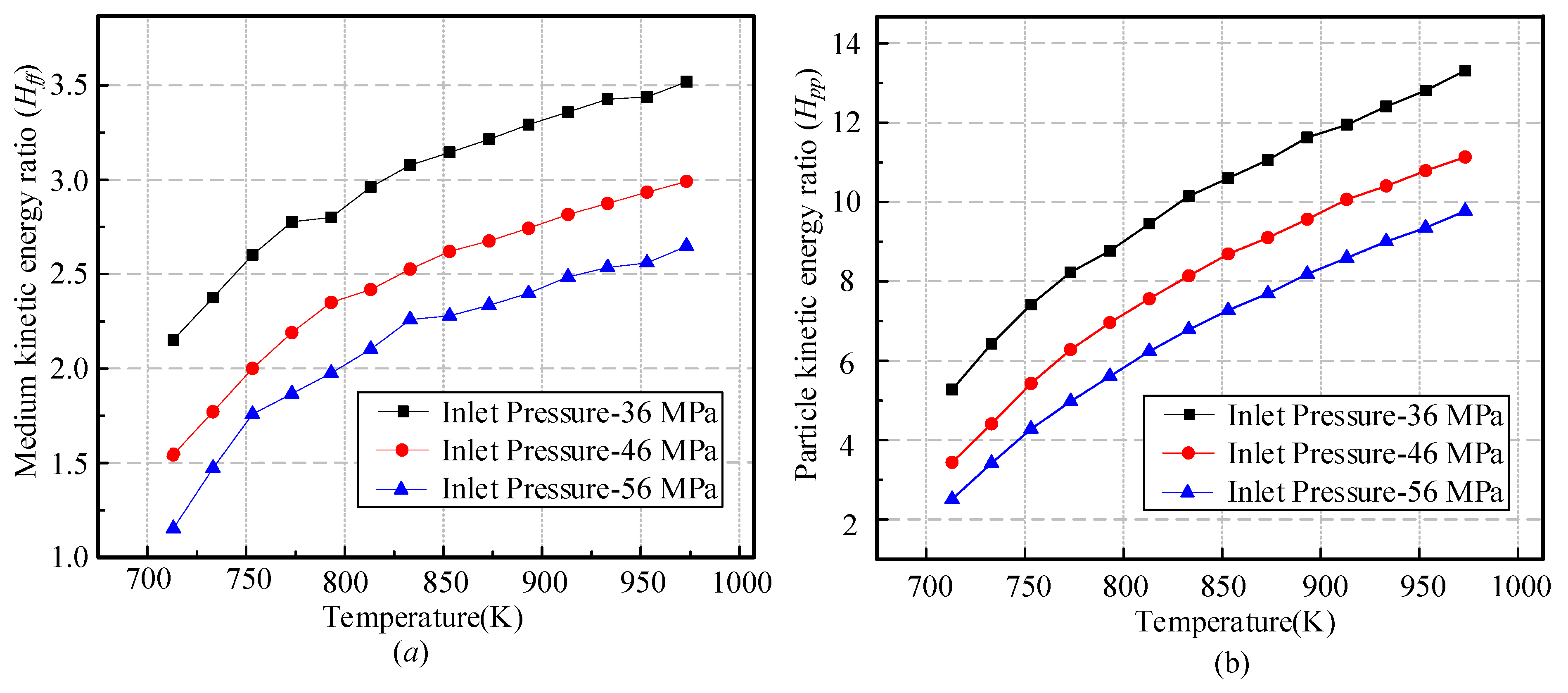
  • At inlet pressures of 36, 46 and 56 MPa, the medium kinetic energy ratio and particle kinetic energy ratio increase with the water temperature significantly, because the input thermal energy increases.
  • The increase in inlet pressure leads to a decrease in both the particle kinetic energy ratio and the medium kinetic energy ratio.
The limitation of the technique is the strong noise produced by the supercritical water jet, which renders it suitable only for the deep-water environment.
Further studies need to be conducted including the enlarged temperature range (subcritical water jet) and the enlarged pressure range (up to 200 MPa). The investigation also needs to be expanded to other subjects in further work, such as the equipment, cost, and impacts on the workpiece surface.

Author Contributions

Writing—original draft preparation, Z.L.; data curation, X.W.; software, Z.L. and F.Y.; writing—review and editing, Z.L.; supervision, S.Y. and L.W.; funding acquisition, F.Y. All authors have read and agreed to the published version of the manuscript.

Funding

This research was funded by National Natural Science Foundation of China (grant number 52001089), National Natural Science Foundation of China (grant number 52371269), Heilongjiang Provincial Natural Science Foundation of China (grant number LH2021E046), and Basic Research Project of Yantai Science and Technology Innovation Development Plan (grant number 2023JCYJ056), Shandong Province Key research and development program (grant number 2021CXGC010706).

Institutional Review Board Statement

Not applicable.

Informed Consent Statement

Not applicable.

Data Availability Statement

Data are contained within the article.

Conflicts of Interest

The authors declare no conflicts of interest.

Nomenclature

mscwThe mass flow rate of supercritical water, kg/s.
mscwpThe mass flow rate of abrasive particles in the supercritical suspended abrasive water jet, kg/s.
vscwThe velocity of supercritical water, m/s.
vscwpThe velocity of abrasive particles in the supercritical suspended abrasive water jet, m/s.
mwpThe mass flow rate of abrasive particles in the conventional suspended abrasive water jet, kg/s.
mwThe mass flow rate of room temperature water, kg/s.
vwThe velocity of room temperature water, m/s.
vwpThe velocity of abrasive particles in the conventional suspended abrasive water jet, m/s.
HffThe medium kinetic energy ratio.
HfpThe particle-medium velocity ratio.
HppThe particle kinetic energy ratio.
ρThe fluid density, kg/m3.
STThe dispersion term of viscosity.
khThe thermal conductivity cofficient, W/(m × K).
μThe dynamic viscosity, N × s/m2.
μtThe turbulent viscosity.
uiThe time-averaged velocity.
GkThe production term of the turbulence kinetic energy.
upThe velocity of the abrasive particles, m/s.
ufThe velocity of the fluid, m/s.
ρpThe density of the abrasive particle, m/s.
ρfThe density of the fluid, m/s.
gGravity acceration, m/s2.
ReReynolds number.
CDDrag coefficient.
kThe turbulence kinetic energy, m2/s2.
εThe turbulent dissipation rate, W/m3.

References

  1. Sun, J.; Gao, Y. Research on the Development of China’s Marine Economy. Reg. Econ. Rev. 2021, 1, 38–47. [Google Scholar]
  2. Liu, S.; Xie, R.; Tong, G.; Wu, Y.; Xu, G. Progress and prospect of deepwater well drilling and completion technique of CNOOC. Acta Pet. Sin. 2019, 40, 168–173. [Google Scholar]
  3. Li, Z.; Xie, R.; Wu, Y. Progress and prospect of CNOOC’s oil and gas well drilling and completion technologies. Nat. Gas Ind. 2021, 41, 178–185. [Google Scholar] [CrossRef]
  4. Fu, W.; Yan, T.; Zhu, Q.; Wang, W. Simulation Analysis and Experimental Research of Hydraulic Cutting Based on LSDYNA. Mach. Des. Manuf. 2024, 1–7. [Google Scholar] [CrossRef]
  5. Ma, Y.; Li, G.; Li, W.; Qu, L. Optimization and application of deep casing cutting methods. Clean. World 2022, 38, 36–38. [Google Scholar]
  6. Chen, J.; Wang, C.; Liu, G.; Liu, Z.; Luo, Q. Casing Cutting Technology through Abrasive Water Jet and Its Applications in Offshore Abandoned Wells. Pet. Drill. Technol. 2013, 41, 46–51. [Google Scholar]
  7. Chu, W.; Liu, L.; Zhang, X. Numerical Simulation Study on CBM Abandoning Well Casing Cutting by Ultra-high Pressure Premixed Abrasive Jet. Coal Mine Mach. 2019, 40, 34–37. [Google Scholar]
  8. Wang, R.; Li, L.; Zhou, W.; Li, H. Experiment and mathematical model of rotary cutting of casing with abrasive water jet. J. China Univ. Pet. 2010, 34, 56–61+66. [Google Scholar]
  9. Wang, M.; Zhang, C. Effect of abrasive blasting on the internal surface of L80-13Cr tubing and casing. Baosteel Technol. Res. 2022, 16, 36–41. [Google Scholar]
  10. Lv, L. Structural design of water jet window opening device for horizontal well casing. West-China Explor. Eng. 2022, 34, 80–82. [Google Scholar]
  11. Shoji, E.; Kikuchi, T.; Yamagiwa, K.; Kubo, M.; Tsukada, T.; Takami, S.; Sugimoto, K.; Ito, D.; Saito, Y. In-situ visualization of heavy oil behavior in supercritical water using neutron radiography-Science Direct. Chem. Eng. Sci. 2020, 17, 1–22. [Google Scholar]
  12. Marcus, Y. Some Advances in Supercritical Fluid Extraction for Fuels, Bio-Materials and Purification. Processes 2019, 7, 156. [Google Scholar] [CrossRef]
  13. Wei, N.; Xu, D.; Hao, B.; Guo, S.; Guo, Y.; Wang, S. Chemical reactions of organic compounds in supercritical water gasification and oxidation. Water Res. 2021, 190, 116634. [Google Scholar] [CrossRef]
  14. Nurcahyani, P.R.; Hashimoto, S.; Matsumura, Y. Supercritical water gasification of microalgae with and without oil extraction. J. Supercrit. Fluids 2020, 165, 25–41. [Google Scholar] [CrossRef]
  15. Zhang, L.; Chen, W.; Ding, C.; Fan, C. Removal mechanism of submerged air jet polishing considering the state of abrasive particles. Int. J. Adv. Manuf. Techol. 2022, 122, 4099–4114. [Google Scholar] [CrossRef]
  16. Fan, J.; Wang, C.; Wang, J. Modelling the erosion rate in micro abrasive air jet machining of glasses. Wear 2009, 266, 968–974. [Google Scholar] [CrossRef]
  17. Mei, L. Engineering Thermodynamics; Tsinghua University Press: Beijing, China, 2019; pp. 21–157. [Google Scholar]
  18. Kolle, J.J. Coiled Tubing Drilling with Supercritical Carbon Dioxide; SPE: Richardson, TX, USA, 2000; SPE 65534. [Google Scholar]
  19. Liu, X.; Liu, J.; Niu, H. Feasibility Study on Supercritical Carbon Dioxide Drilling Equipment. Appl. Mech. Mater. 2013, 318, 519–521. [Google Scholar] [CrossRef]
  20. Zheng, Y.; Zhang, Z.; Wang, Z.; Pang, M.; Ma, L.; Su, J. An Exploration of the Influence of Abrasive Water Jet Pressure on the Friction Signal Characteristics of Fixed Abrasive Lapping Quartz Glass Based on HHT. Micromachines 2023, 14, 891. [Google Scholar] [CrossRef]
  21. Xing, H. Supercritical Fluid Science and Technolog; China Petrochemical Press: Beijing, China, 2005; pp. 2–27. [Google Scholar]
  22. Wang, F. Computational Fluid Dynamics Analysis; Tsinghua University Press: Beijing, China, 2004; pp. 24–137. [Google Scholar]
  23. Cheng, Z.; Qin, S.; Fang, Z. Numerical Modeling and Experimental Study on the Material Removal Process Using Ultrasonic Vibration-Assisted Abrasive Water Jet. Front. Mater. 2022, 9, 77–89. [Google Scholar] [CrossRef]
  24. Brucato, A.; Montante, G.; Grisafi, F. Particle drag coefficients in turbulent fluids. Chem. Eng. Sci. 1998, 53, 3295–3314. [Google Scholar] [CrossRef]
  25. WANG, M.; WANG, R. Analysis of forces acting on abrasive particles in abrasive water jet. J. China Univ. Pet. 2006, 30, 47–49. [Google Scholar]
  26. XU, B.; YU, A. Numerical simulation of the gas-solid flow in a fluidized bed by combining discrete particle method with computational fluid dynamics. Chem. Eng. Sci. 1997, 52, 2785–2809. [Google Scholar] [CrossRef]
  27. Schuler, M.J.; Rothenfluh, T.; Stathopoulos, P.; Brkic, D.; Meier, T.; Rudolf von Rohr, P. Simulating supercritical water jets with a variable turbulent prandtl Number. Chem. Eng. Technol. 2014, 37, 1896–1902. [Google Scholar] [CrossRef]
  28. Adschiri, T. Plenary lecture “Supercritical Fluids Technology for Nanotechnolog” at the International Symposium on Supercritical Fluids. In Proceedings of the International Symposium on Supercritical Fluids, Miami, FL, USA; 2000. [Google Scholar]
  29. Hu, X.; Song, X.; Li, G. The calculation of Joule Thomson coefficient of supercritical water jet flow and the analysis on cooling effect in the process of throttling. Oil Drill. Prod. Technol. 2017, 39, 163–168. [Google Scholar]
  30. Wang, J.; Wang, Z.; Sun, B. Improved equation of CO2 Joule–Thomson coefficient. J. CO2 Util. 2017, 19, 296–307. [Google Scholar] [CrossRef]
  31. Augustine, C.R. Hydrothermal Spallation Drilling and Advanced Energy Conversion Technologies for Engineered Geothermal Systems. Ph. D. Thesis, Massachusetts Institute of Technology, Cambridge, MA, USA, 2009. [Google Scholar]
Figure 1. The supercritical suspended abrasive water jet.
Jmse 12 00655 g001
Figure 2. Material properties of the supercritical water. The density (a), the specific heat capacity (b), the thermal conductivity (c), and the viscosity (d).
Jmse 12 00655 g002
Figure 3. Geometric model of the nozzle.
Jmse 12 00655 g003
Figure 4. Boundary conditions, monitoring points, and surfaces.
Jmse 12 00655 g004
Figure 5. Simulation flowchart.
Jmse 12 00655 g005
Figure 6. Simulation model meshing and refinement.
Jmse 12 00655 g006
Figure 7. Element number effects on the simulation results.
Jmse 12 00655 g007
Figure 8. Jet velocities of the supercritical water and abrasive particles along the axis.
Jmse 12 00655 g008
Figure 9. Velocity distributions of supercritical suspended abrasive water jet and conventional suspended abrasive water jet.
Jmse 12 00655 g009
Figure 10. Radial velocity distribution of the supercritical suspended abrasive water jet.
Jmse 12 00655 g010
Figure 11. The distributions of the density, viscosity, and temperature in the axial section and along the axis.
Jmse 12 00655 g011
Figure 12. The effects of parameters on the acceleration process of abrasive particles: (a) water temperature; (b) inlet pressure; (c) particle size; (d) abrasive particle density.
Jmse 12 00655 g012
Figure 13. Effects of water temperature on jet kinetic energy characteristics: (a) medium kinetic energy ratio; (b) particle kinetic energy ratio.
Jmse 12 00655 g013
Figure 14. Effects of inlet pressure on jet kinetic energy characteristics: (a) medium kinetic energy ratio; (b) particle kinetic energy ratio.
Jmse 12 00655 g014
Table 1. Parameters and values.
ParameterValueBenchmark
Water temperature (K)673.15 to 973.15 with step of 20773.15
Inlet pressure (MPa)30 to 60 with step of 236
Particle size (mm)0.10, 0.15, 0.200.15
Abrasive density (kg/m3)2000, 4000, 60004000
Table 2. Density comparison.
Temperature (K)673.15698.15723.15748.15773.15798.15
Experimental result (kg/m3)166.5126.8109.097.889.783.5
Simulation result (kg/m3)169.68129.75112.5199.5991.0684.3
Error (%)1.912.333.221.831.520.96
Table 3. Material properties.
MediumDensity
(kg/m3)
Viscosity
(Pa-s)
Thermal Conductivity
(W/(m × K))
Enthalpy
(kJ/kg)
Cp
(J/kg-K)
Supercritical water151.263.38 × 10−513.35 × 10−22978.105237.2
Room temperature water998.2110.02 × 10−459.81 × 10−284.104183.7
Table 4. Comparison with the conventional suspended abrasive water jet.
MediumJet Velocity (m/s)Mass Flow Rate (kg/s)Et-medium (J/s)Et-particle (J/s)
Room temperature water137.70.093882.056.46 × 10−5
Supercritical water402.40.0302449.915.32 × 10−4
Increase (%)+192.2−67.7%+177.7+723.2
Disclaimer/Publisher’s Note: The statements, opinions and data contained in all publications are solely those of the individual author(s) and contributor(s) and not of MDPI and/or the editor(s). MDPI and/or the editor(s) disclaim responsibility for any injury to people or property resulting from any ideas, methods, instructions or products referred to in the content.

