Article

Physical Experimental Study on the Wave Reflection and Run-Up of a New Ecological Hollow Cube

1
School of Water Conservancy and Environment Engineering, Zhejiang University of Water Resources and Electric Power, Hangzhou 310018, China
2
School of Marine Engineering Equipment, Zhejiang Ocean University, Zhoushan 316022, China
3
Shaoxing Shunjiangyuan Provincial Nature Reserve Management Center, Shaoxing 312000, China
4
Key Laboratory of Ocean Space Resource Management Technology, MNR, Hangzhou 310012, China
5
Marine Academy of Zhejiang Province, Hangzhou 310012, China
6
Haining City Water Conservancy Construction Management Co., Ltd., Jiaxing 314400, China
*
Author to whom correspondence should be addressed.
J. Mar. Sci. Eng. 2024, 12(4), 664; https://doi.org/10.3390/jmse12040664
Submission received: 12 March 2024 / Revised: 6 April 2024 / Accepted: 12 April 2024 / Published: 17 April 2024
(This article belongs to the Special Issue Wave Interactions with Coastal Structures II)

Abstract

:
Implementing quadrangular hollow blocks on breakwaters is a common method for wave mitigation and ocean disaster prevention. In order to improve the wave-damping performance of conventional quadrangular hollow blocks, a new quadrangular hollow block is proposed. In this study, a series of physical modeling experiments were conducted in a two-dimensional wave flume to investigate the wave reflection and wave run-up height of a new quadrilateral hollow block under regular wave action. Test results showed that wave reflection and wave run-up height decreased with the breakwater slope. The wave run-up height increased with wave height, and the reflection coefficient decreased with wave height. Wave reflection and run-up height increased with the wave period. The reflection coefficient of the new quadrangular hollow blocks was lower than that of the conventional quadrangular hollow blocks and decreased with frame height. In addition, this study found that the reflection coefficient and relative run-up height increased with the average wave breaking parameter. The new quadrilateral hollow block has advantages in wave mitigation compared to the conventional quadrilateral hollow block.

1. Introduction

Armor blocks are the main structures responsible for wave breaking and energy dissipation in coastal protection engineering, usually made of natural rock blocks or artificial concrete blocks [1]. The implementation of armor blocks on breakwaters [2] is a typical method of wave mitigation and marine disaster prevention. Unlike natural rock blocks, artificial armor blocks, such as Accropode® and quadrangular hollow blocks, are easier to obtain and more stable. These artificial armor blocks are widely used in practical engineering for coastal protection [3]. The use of armor blocks, including Accropode®, Xbloc®, and Core-LocTM, has become a classic solution for the construction of coastal structures [2]. The new armor blocks [4,5,6] allow for improved dissipation of wave energy and decreased usage of concrete. There is a great deal of uncertainty about how to effectively protect coastal structures from longer and larger waves in coastal waters, and these structures will be more susceptible to marine hazards associated with global warming [7]. Using armor blocks in breakwater and coastal protection projects effectively achieves the safety functions of disaster prevention and erosion control. However, they tend to give less consideration to the impact on the environment, which can easily lead to various ecological problems [8,9]. How to enhance the ecological and landscape value of coastal protection works on the basis of safeguarding their safety functions is a challenging dilemma [10].
Currently, the construction of ecological coastal protection projects can be divided into two main forms. The first form relies entirely on natural structures and materials for coastal protection, such as natural vegetation like mangroves [11] or artificially cultivated reefs [12,13]. While natural breakwaters are more ecologically sound, they require more construction space and a longer construction period. The second form is the addition of ecological structures to the intertidal zone in front of conventional coastal protection facilities to mitigate negative impacts on the ecosystem [14]. Examples of this include adding rock cavities to the armor block to provide additional habitat [15], thereby increasing biodiversity and richness, or combining vegetation with engineered coastal protection to not only reduce wave action [16] but also provide habitat for organisms [17]. This design approach reduces costs and is therefore widely used in practice [18].
However, since wave dynamics on seaward slopes are usually complex, it is often necessary to rely on armor blocks to break waves and dissipate energy. Therefore, the design of seaward slopes usually gives priority to satisfying the wave breaking and energy dissipation functions of the armor block before moderately pursuing the enhancement of ecological greening effects. Mohammad [19] proposed a new type of armor block that can support vegetation growth and evaluated its ecological and hydraulic performance through laboratory and field testing. Scheres and Schüttrumpf [20] provide an overview of the structure, function, and current design practices for vegetative cover on dike surfaces. Le Xuan [21] summarized the experiences and lessons learned from typical coastal protection projects in the Mekong Delta, Vietnam, and proposed a multiline defense solution incorporating “seawall/coastal protection + mangroves + offshore breakwater” with vegetation greening on the seaward slopes to enhance the landscape effect. Chen [22] discussed the marine ecological protection and restoration program by taking the Taiping Bay reclamation project of Dalian Port as an example and proposing a slope-type ecological seawall that used blocks of stone as the berm material and improved the ecological and landscape quality of the berm by planting saline and alkaline plants such as shrubs and grasses. Martinez [23] analyzed the stability of COASTALOCK, a new ecological armor block that mimics natural rock pools while creating localized ecosystems and promoting biodiversity through physical modeling tests.
Ecological armor blocks are usually placed on slopes to reduce wave run-up while also producing ecological effects. Currently, there are more adequate studies on the run-up of waves on slopes. Dutykh et al. [24] considered the problem of the long-wave run-up of rough bottoms and proposed a stochastic model to simulate natural bottom roughness. The effect of bottom roughness on the maximum run-up height is also investigated. A stochastic model describing the bottom irregularity is proposed, which has practical significance. Torsvik et al. [25] used numerical models based on the finite volume method applied to the modified nonlinear shallow water (NLSW) and modified Peregrine equations (Durán et al., [26]; Dutykh et al., [27]) and emphasized the theoretical framework and the development of equations of motion for shallow water long waves. This provided an important basis for the subsequent discussion of tsunami wave propagation and run-up on sloping beaches. In addition, Didenkulova and Pelinovsky [28] investigated the effect of incident wave form on the extreme (maximum) characteristics (run-up and draw-down heights, run-up and draw-down velocities, and breaking parameters) of waves on the beach. Bouard et al. [29] studied the motion of the free surface of a fluid over a variable bottom in a long-wave asymptotic regime and demonstrated that the ultimate effect of random topography is represented by a typical process.
Based on the conventional quadrilateral hollow block, this paper proposes a new type of ecological armor block. The reflection coefficients and wave run-up heights of the blocks were analyzed by physical modeling tests. Meanwhile, the influence of the height of the upper frame of the block on the wave dissipation performance is also discussed. No coastal plants are currently planted within the blocks based on two main considerations: (1) The general construction process for breakwater involves the installation of the blocks, followed by the addition of soil and the planting of coastal plants within the planting groove. Breakwaters typically have long construction and coastal plant growth cycles. During construction and until coastal plants are fully grown, breakwaters may be subject to waves. (2) The plants and soil in the planting grooves will be the first to suffer damage in the event of extreme weather, such as storm surges, when only the block itself will be left to withstand the impact of the storm surge. Considering the above practical situations, we divided the study into two cases: one is to study the wave dissipation effect of blocks alone, and the other is to consider the effect of both coastal plants and blocks together. In this study, only cases where no vegetation was planted within the block during the construction of the breakwater or where the littoral vegetation had not yet fully grown were considered, as well as cases where only the block itself remained under extreme climatic conditions. The rest of this paper is organized as follows: Section 2 describes the model and the research methodology. Section 3 presents the results and discussion. Finally, Section 4 summarizes the main conclusions and recommendations of the study.

2. Materials and Methods

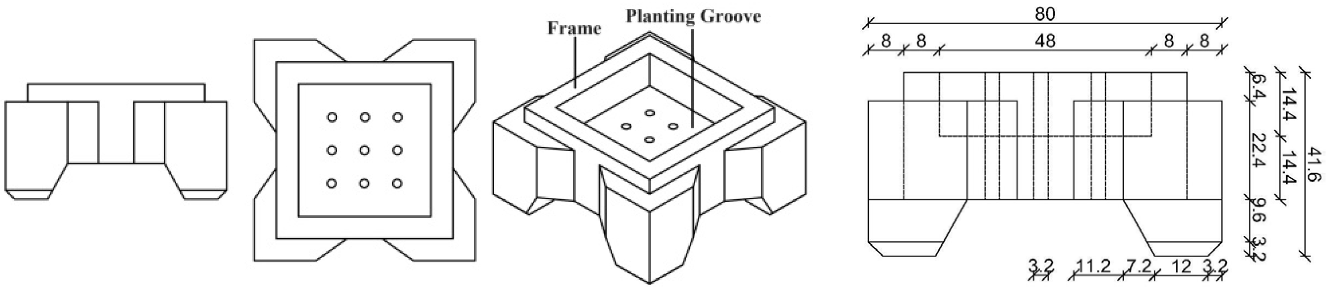
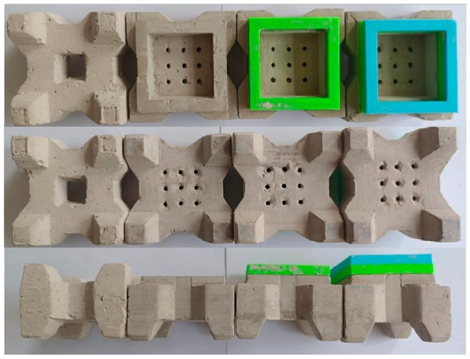
2.1. Block Description

The new ecological armor block is transformed from the conventional quadrilateral hollow block. Based on conventional quadrilateral hollow blocks with a raised frame and appropriate digging down to form a planting groove, nine cavities are arranged in the planting groove for wave dissipation. The shape of the block and the definition of the dimensions are shown in Figure 1. The wave dissipation mechanism of the block is as follows: Waves create a vortex as they enter the chambers formed by the block during their run-up the slope. Energy is dissipated during the interaction of the wave with the surface of the chamber to achieve wave dissipation. The new block has the advantages of high porosity, strong wave dissipation, and structural stability. The ecological performance of breakwaters can be improved by increasing the biomass on the surface of the breakwater by planting coastal plants in planting grooves. However, it may take considerable time for the coastal plants to grow fully [30,31,32,33]. It is therefore necessary to study the stability of the blocks when no coastal plants are planted.
Considering a new ecological armor block with a side length of 2 m (weighing approximately 5.5 t), physical model tests were conducted following the principle of gravity similarity. We considered practical factors such as laboratory field conditions, available instrumentation, availability of materials, and implementation conditions of the test. Accordingly, we determined the geometric scale of the model as 1:25. Based on the gravity similarity criterion, the following scale relationships for physical quantities were derived:
Wave   Height   Ratio   Scale :   λ H = λ l = 25
Wave   length   ratio   scale :   λ L = λ l = 25
Wave   period   scale :   λ T = λ l = 5
New ecological blocks are placed on a smooth slope to study the reflection coefficient of the blocks and the wave run-up. Four different slope ratios were considered: 1:1.5, 1:2, 1:2.5, and 1:3. Additionally, three different water depths at the toe of the dike were considered: 7.5 m, 8.75 m, and 10 m.

2.2. Physical Model Experiments

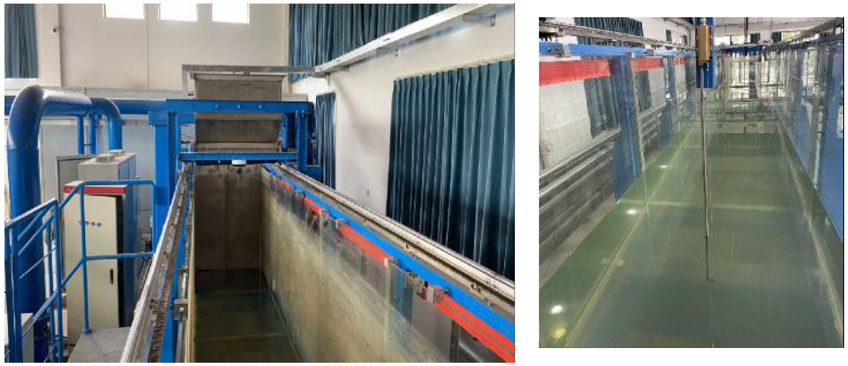
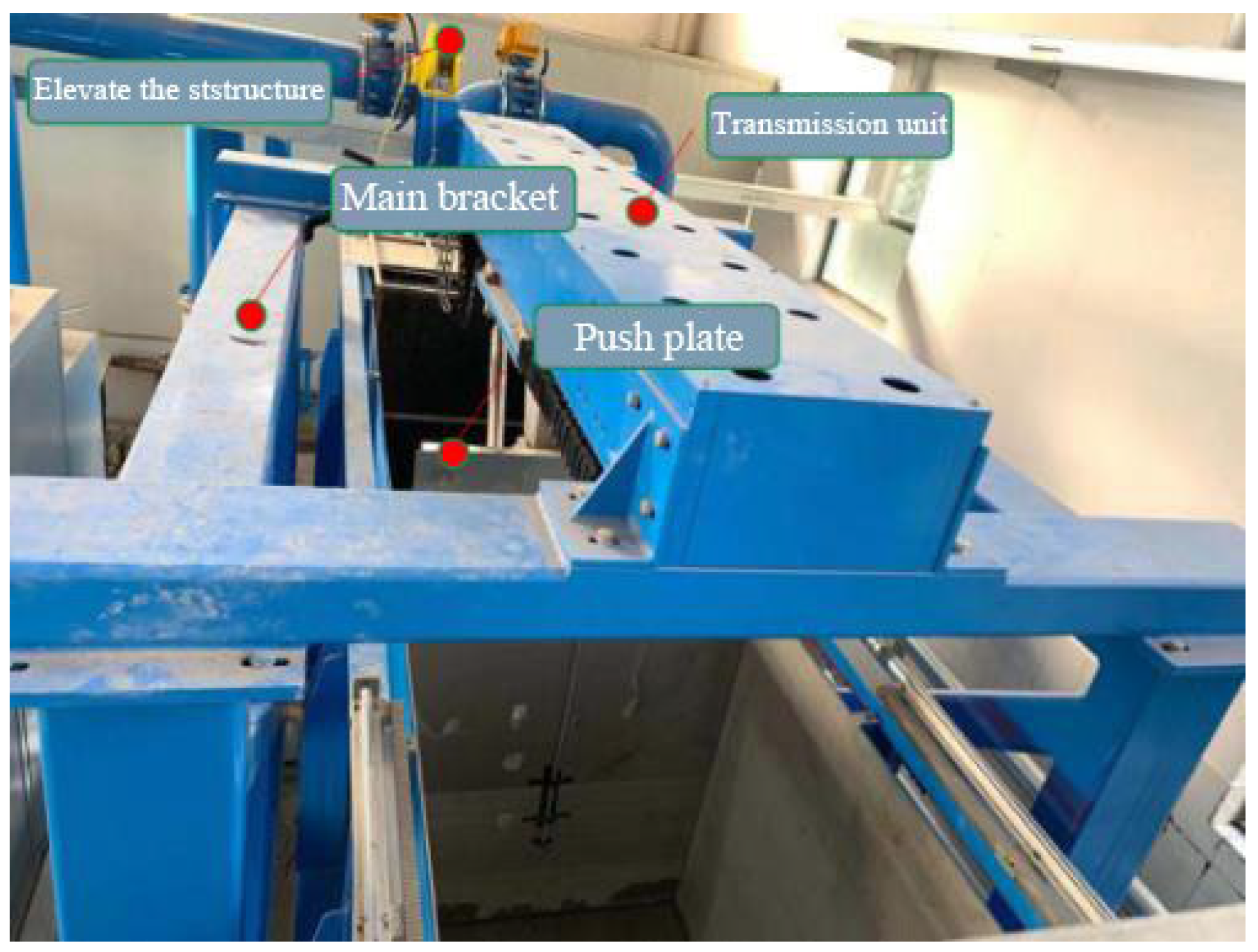
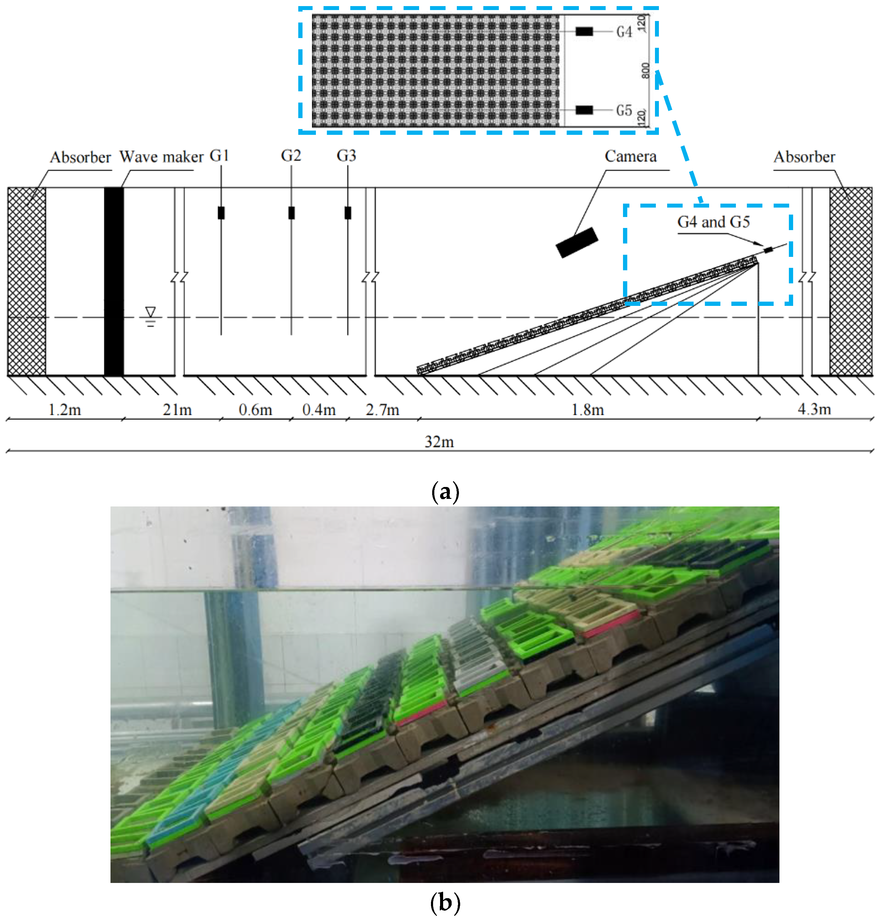
2.2.1. Experimental Equipment and Instruments

The physical modelling tests were undertaken in a two-dimensional wave flume at Zhejiang University of Water Resources and Electric Power in China. The flume has dimensions of 32.0 (L) × 0.8 (W) × 1.0 (H) m. Figure 2 illustrates a two-dimensional wave flume. The flume is equipped with a piston-type wavemaker and an active wave absorption system (AWAS). Figure 3 illustrates the wavemaker. It can actively absorb secondary reflected waves, and the absorption rate of regular waves reaches more than 90%. Energy dissipation nets were installed on both ends of the flume to mitigate the effects of wave reflection. Wave height was measured using a DS30 multichannel wave height acquisition system.

2.2.2. Experimental Setup and Procedure

To investigate the effect of frame height on the wave dissipation performance, two modified blocks with different frame heights were made while maintaining the overall structure of the new block unchanged. The model section was a sloping structure consisting of two layers of impermeable tiles and aluminum profiles. The armor blocks were placed regularly on the slope using four different schemes. Figure 4 displays the armor blocks used in the model, from left to right, which correspond to the conventional quadrilateral hollow block (referred to as the “Conventional block”), the new ecological quadrilateral hollow block (referred to as the “New block”), and the modified blocks with one additional layer (referred to as “New High 1,” which corresponds to the green frame in Figure 4) and two additional layers (referred to as “New High 2”, which corresponds to the blue frame in Figure 4) of frame height for the new block. The prototype dimensions of each type of block are shown in Table 1.
Physical model test conditions were determined based on slope gradient, water depth, wave height, and period under different armor block schemes. Table 2 shows that the experimental data are presented on a prototype scale. Table 3 shows the experimental data scaled to the model. Regular waves were used in each set of test conditions and repeated twice to ensure the repeatability of the experimental data.

2.2.3. Experimental Layout

The model section is 24.7 m from the wavemaker. For data collection, a wave gauge was set up at 2.7 m, 3.1 m, and 3.7 m at the toe of the slope, respectively. Wave surface data are collected using three wave gauges, and then the data are imported into the two-point method twice [34] to obtain the average wave reflection coefficient. High-definition cameras were arranged vertically above and on the side of the slope to record the propagation and deformation of waves on the slope. In addition, one wave gauge was placed on each side of the second row of blocks on the slope to enable future wave run-up calculations. The specific experimental layout is shown in Figure 5.

3. Results and Discussion

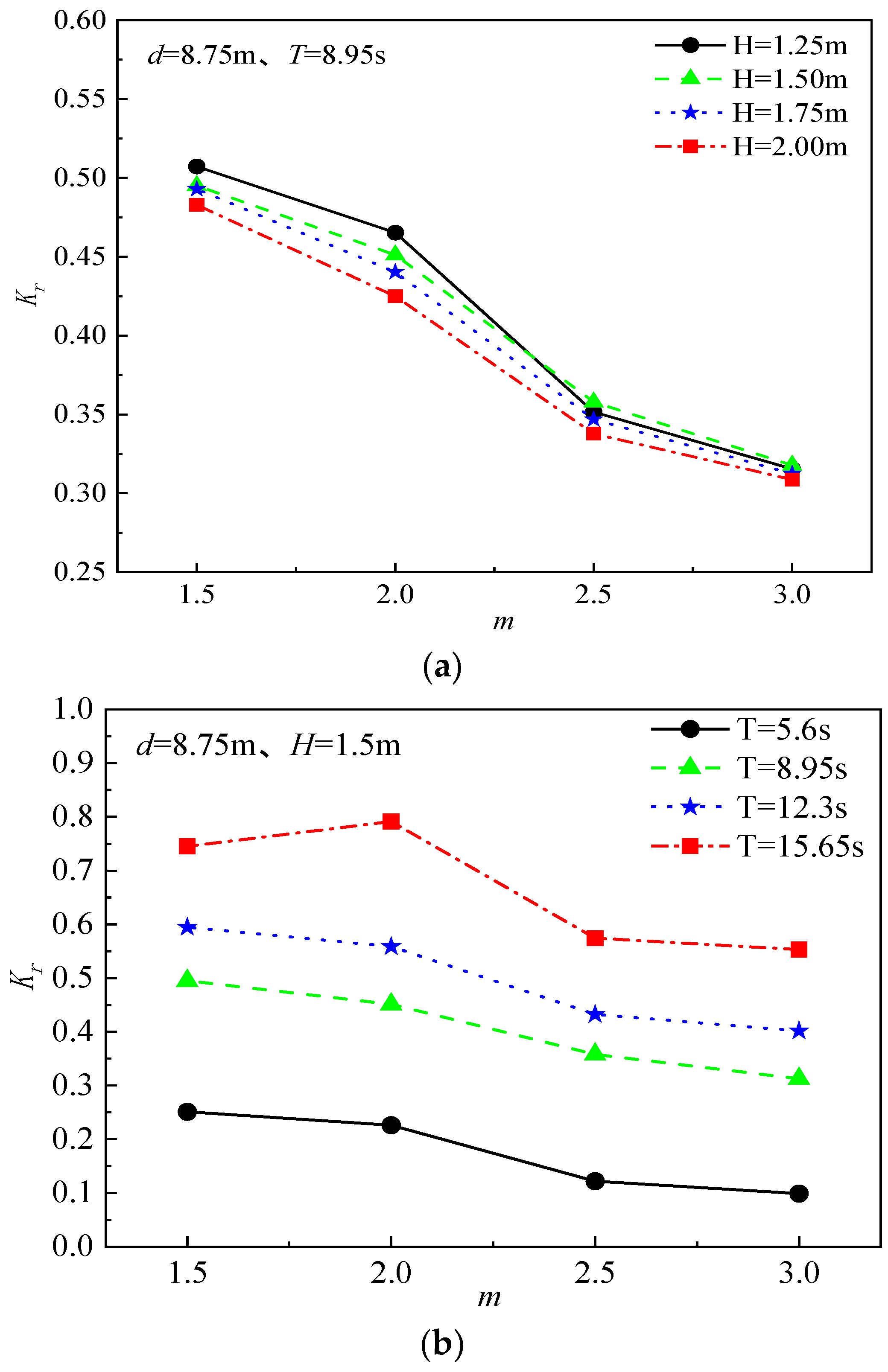
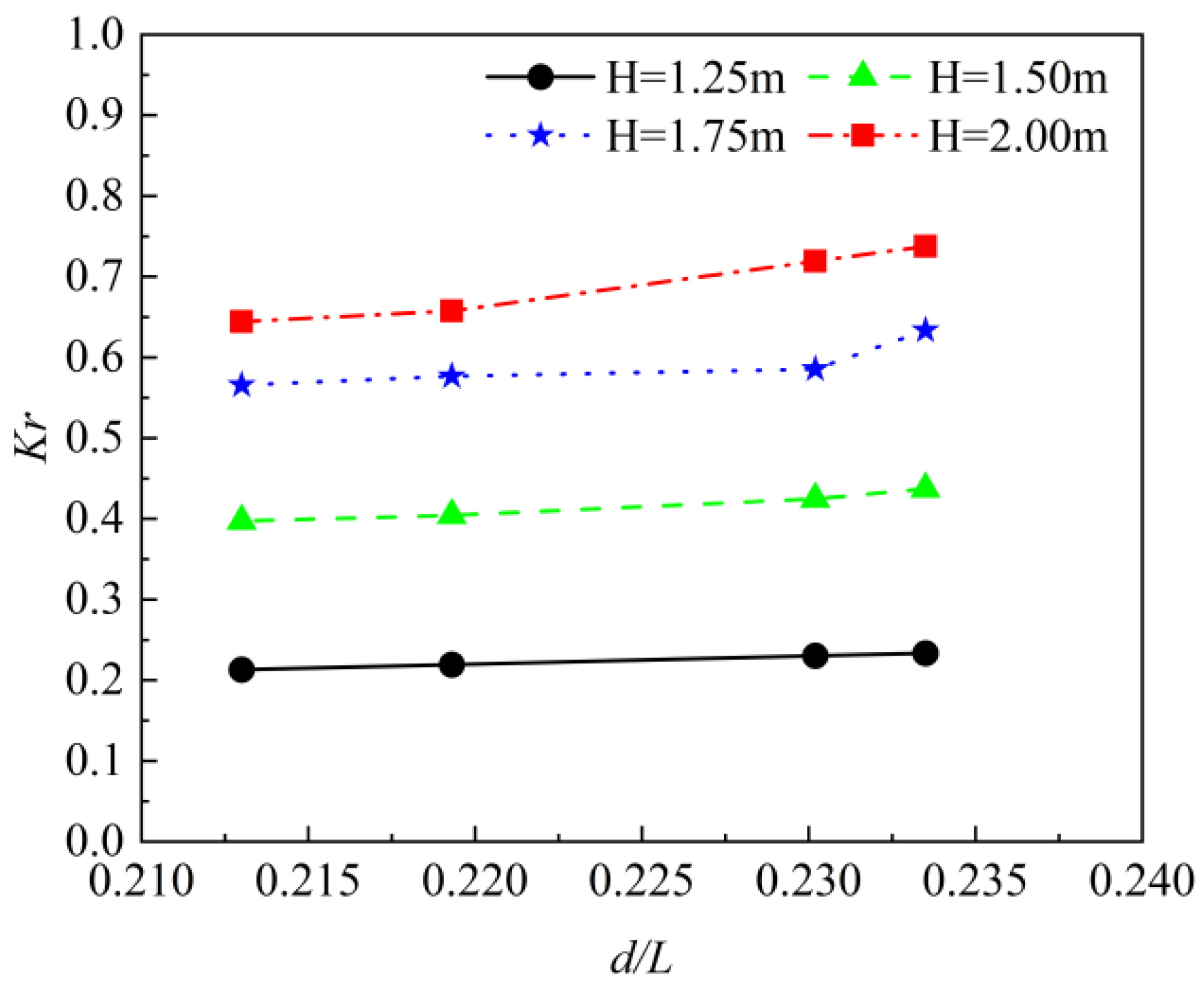
3.1. Analysis of the Reflection Coefficient for the New Block

In this study, incident and reflected waves are separated by using the method proposed by Mansard and Funke [35]. The reflection coefficient is the ratio of the reflected wave height to the incident wave height. Typically, the factors affecting the wave attenuation effectiveness of an armor block are slope gradient, incident wave characteristics, and water depth at the toe of the structure. Figure 6 shows the influence of slope gradient on the reflection coefficient of the new block under different incident wave heights and periods when the test water depth is 8.75 m. Figure 6 demonstrates that the reflection coefficient decreases as the slope decreases. This may be due to the fact that as the slope gradient becomes smaller, more water enters the planting groove during wave run-up. Under the influence of slope friction and turbulence in the planting groove, the energy lost by the waves becomes larger, resulting in a decrease in the energy of the reflected waves. For the same slope, the higher the wave height and the smaller the period, the lower the reflection coefficient. This may be due to the fact that an increase in wave height and a decrease in period leads to an increase in the steepness of the wave, which in turn makes it more likely to break on slopes, where wave breaking consumes more energy.
Figure 7 shows the relationship between the reflection coefficient and relative water depth for a slope of 1:2. The reflection coefficient increased with increasing relative water depth, which was observed at all four wave heights. There is also an effect of wave height on the relationship between relative water depth and reflection coefficient. The effect of relative water depth on the reflection coefficient is small when the wave height is small, such as H = 1.25 m, while the effect of relative water depth on the reflection coefficient is large when the wave height is large, such as H = 2.00 m.

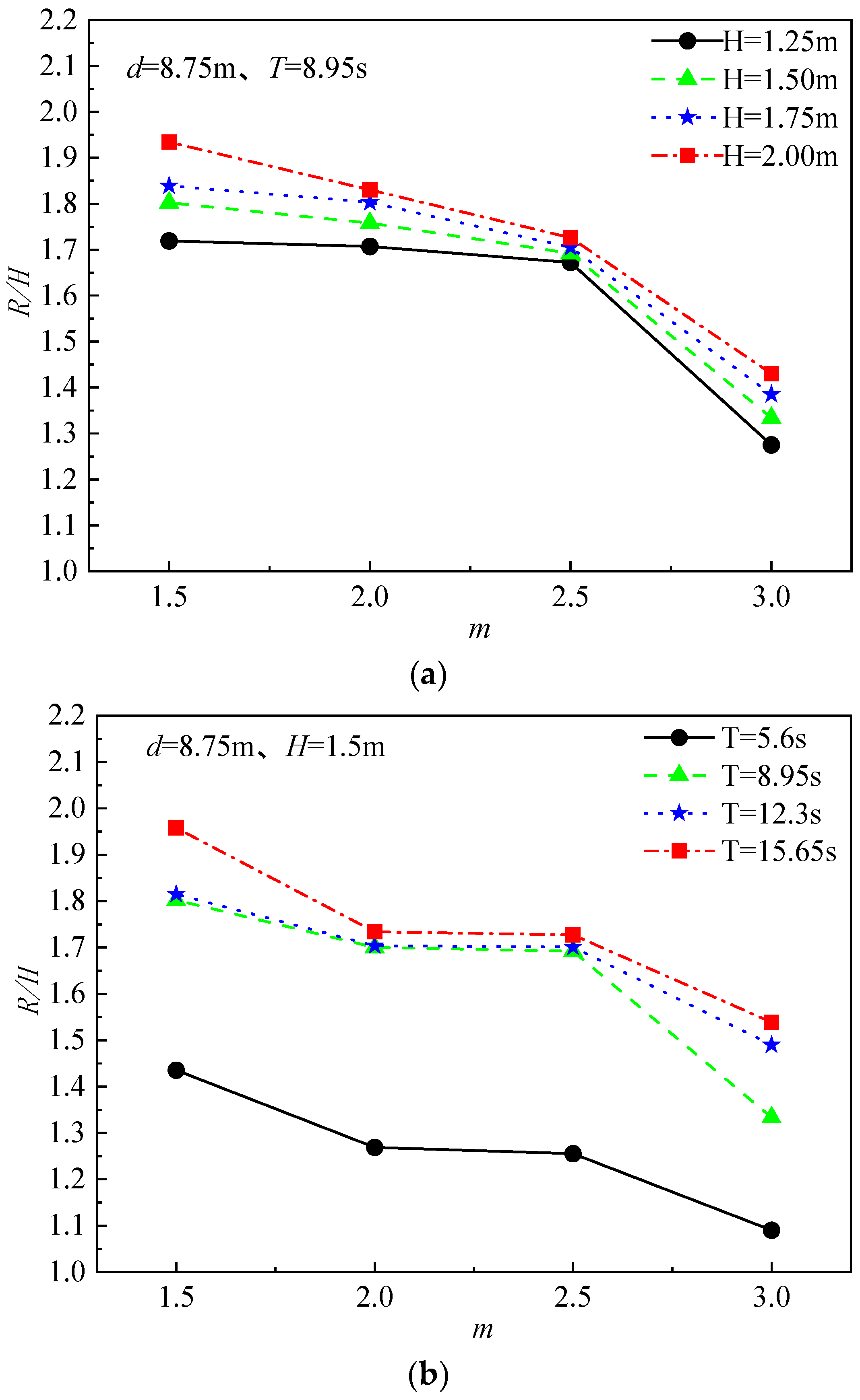
3.2. Analysis of the Wave Run-Up of the New Block

The wave run-up height used in this study is Ru2%. This is the wave run-up level, measured vertically from the still water line, which is exceeded by 2% of the number of incident waves [36]. Figure 8 presents the influence of slope gradient on wave run-up under different incident wave conditions, with a water depth of 8.75 m. As the slope slows down, the relative wave run-up height continues to decrease. In Figure 8a, the relative wave run-up height falls slowly as the slope gradient changes from 1:1.5 to 1:2.5. This may be due to the fact that as the slope changes from 1:1.5 to 1:2.5, the wave reflection decreases (Figure 6) and the wave breaking increases, resulting in an increase in wave breaking energy that exceeds the decrease in reflected wave energy, which ultimately results in a slight decrease in the rate of wave run-up height. As the slope gradient increases, the energy lost due to slope friction and turbulence increases significantly, resulting in a sharp decrease in the height of wave run-up. It can be concluded that the relative wave run-up height decreases with slope gradient. In addition, Figure 8a shows that for slopes of the same gradient, the greater the incident wave height, the higher the wave run-up height. Figure 8b shows that the wave run-up height from waves with shorter periods is noticeably lower than from waves with longer periods.
Figure 9 shows the relationship between wave run-up and relative water depth for a slope of 1:2, from which it can be seen that relative run-up height R/H decreased with increasing relative water depth, which was observed for all four wave heights. In addition, we find that the two sets of conditions with wave heights H = 1.5 m and 1.75 m undergo a plunge in relative run-up height when the relative water depth increases from 0.2302 to 0.2335. This may be due to the fact that these two sets of conditions are most affected by d/L.

3.3. Comparison of Reflection Coefficient and Wave Run-Up for Different Blocks

In order to study the differences in wave dissipation between the new block and the conventional block, we investigated the effect of frame height on the reflection coefficient and wave run-up in the new block. Figure 10 and Figure 11 provide a comparison of the reflection coefficients and wave run-up height for a different armor block. Figure 10a shows that the reflection coefficients of the new blocks are generally lower than those of the conventional blocks, the wave dissipation effect of larger wave heights is better than that of smaller wave heights, the reflection coefficients of the waves decrease significantly with the increase in the frame height, and the difference in reflection coefficients between different wave heights decreases gradually.
According to Figure 10b,c, for different wave periods and experiment water depths, the reflection coefficients of the new block are lower than those of the conventional block, and the wave dissipation effectiveness of the block improves with the increase in frame height. A possible reason for this is that as the frame height of the planted groove in the armor block increases, there is increased frictional resistance on the breakwater slope. More water flows into the groove during the run-up process, increasing turbulent energy consumption. Ultimately, this leads to a reduction in the energy of the reflected waves.
Figure 11 shows a comparison of the relative run-up height between the different blocks. The wave run-up characteristics of the new block are not significantly better than those of the conventional block. In fact, for larger wave heights, the new block’s wave run-up height is even greater (Figure 11a). Furthermore, there is no apparent trend of decreased wave run-up with increasing frame height. Based on the analysis of the experimental phenomena, the increase in the frame’s height hinders the backflow of water on the slope. It may reduce the resistance to wave run-up and lead to wave run-up.

3.4. Influence of the Average Breaking Parameter ξ on the Reflection Coefficient and Wave Run-Up of New Blocks

Considering the significant impact of wave breaking on waves, the average breaking parameter ξ is introduced, with a value of tanα/(H/L)0.5, where α represents the slope gradient, and H and L represent the wave height and wavelength at the toe of the seawall. Figure 12a shows that the reflection coefficients increase with an increasing average breaking parameter ξ. When the average breaking parameter ξ is between 2.3 and 2.9, the blocks’ reflection coefficients are relatively concentrated and small. Within this range, the increment of reflection coefficients with the increase in the average breaking parameter ξ is very small. When ξ ranges from 3 to 4.1, the wave breaking type changes from plunging to surging, and the overall reflection coefficient is noticeably greater than the reflection coefficient when ξ ranges from 2.3 to 2.9. Additionally, during this range, the reflection coefficient is concentrated and increases slowly with the increase in ξ. When ξ exceeds 4.2, the reflection coefficient is significantly larger and more dispersed, possibly due to longer wave periods resulting in poorer wave dissipation effectiveness of the blocks. Figure 12also indicates that the reflection coefficient of the new block is somewhat lower than that of the conventional block, and this trend becomes more pronounced with the increase in frame height. The reflection coefficient of the new blocks was reduced by an average of 4.25% compared to the conventional blocks, by an average of 11.66% for New High 1 and by an average of 18.86% for New High 2.
For wave run-up, the relative run-up height R/H decreases with increasing ξ when ξ is between 2.3 and 2.9. When ξ is between 3 and 4.1, the overall relative run-up height R/H is greater than when ξ is between 2.3 and 2.9. The reason for this is that ξ is generally relatively high at this time, and less energy is lost to wave breaking, resulting in a higher relative run-up height. When ξ is greater than 4.2, the relative run-up height R/H shows an increasing trend. This may be because the wave tends not to break or has a surging breaker.
According to the [36] study, the general formula that can be applied for the 2%-wave run-up height for relatively gentle slopes (1:2.0 and gentler) is given by Equation (4).
R u 2 % H = 1.65 × γ b × γ f × γ β × ξ
where Ru2% is the wave run-up height exceeded by 2% of the incoming waves [m], γ b is the influence factor for a berm, which is 0 in the absence of a berm; γ f is the influence factor for roughness elements on a slope, the value is 0 when the slope is smooth, γ β is the influence factor for oblique wave attack, and ξ is the breaker parameter. When the wave is not obliquely incident, the influence factor is γ β 0.

4. Conclusions

In this study, a series of two-dimensional wave flume physical model tests were conducted to understand the reflection coefficient and wave run-up height of the new ecological block, to compare and analyze the reflection coefficient and wave run-up height of the conventional block and the new block, and to investigate the effect of the frame height of the new block on the reflection coefficient and wave run-up height. The main conclusions of this study are as follows:
(1)
The effects on the reflection coefficients of the new blocks are investigated by varying the incident wave height, period, water depth, and slope gradient. The results show that as the slope gradient increases from 1:1.5 to 1:3, the reflection coefficient of the new block decreases continuously. The reflection coefficient decreases with increasing wave run-up height and decreasing period. In addition, it was found that the relative water depth had little effect on the reflection coefficient.
(2)
The effect on the wave run-up height in the new block was investigated by varying the incident wave height, period, water depth, and slope gradient. The results showed that as the slope gradient decreases, the relative run-up height decreases sharply. The wave run-up height increases as the wave height and period increase.
(3)
By comparing the reflection coefficient and wave run-up height between the new block and the conventional block, it is concluded that the reflection coefficient of the new block is lower than that of the conventional block and further decreases with the elevation of the frame of the planting groove, but the wave run-up height of the new block does not significantly decrease with the elevation of the frame of the planting groove
(4)
Changing the average breaking parameter ξ has an effect on the reflection coefficient and wave run-up in the new block. As ξ increases gradually from 2.3 to 5.32, the reflection coefficient and wave run-up height increase with ξ. When ξ reaches 2.9 and 4.1, the reflection coefficient increases significantly and the wave run-up decreases substantially. Compared to the average reflection coefficients of the conventional quadrilateral hollow blocks, the average reflection coefficients of the new blocks were reduced by 4.25%, the average reflection coefficients of the new height 1 were reduced by 11.66%, and the average reflection coefficients of the new height 2 were reduced by 18.86%.
In addition to the above conclusions, the limitations and future prospects of this study are also pointed out here. First, to simplify the study, we used regular waves. The interaction of new blocks with complex wave climates, such as irregular waves and tsunamis, should be further investigated in future work. In addition, the results of this study are only for the case where there are no coastal plants within the blocks during the construction of the breakwater or during extreme weather strikes, and future studies related to the reflection coefficients and wave run-up of the blocks with coastal plants will be conducted.

Author Contributions

Conceptualization, H.Z., F.D. and J.Y.; Methodology, H.Z. and H.J.; Software, H.Z. and W.G.; Validation, G.Y. and Q.L.; Investigation, H.Z. and G.Y.; Formal Analysis, H.Z., J.Y. and H.J.; Resources, F.D. and G.Y.; Data Curation, H.J. and W.G.; Writing—Original Draft, H.Z. and F.D.; Writing—Review and Editing, J.Y., W.C. and Q.L.; Visualization, W.C. and H.J.; Supervision, F.D., J.Y., W.C. and Q.L.; Project Administration, W.G. and G.Y.; Funding Acquisition, F.D. and Q.L. All authors have read and agreed to the published version of the manuscript.

Funding

This research was funded by the Open Fund of Key Laboratory of Marine Spatial Resource Management Technology, MNR, Zhejiang Province, China, grant numbers KF-2022-110, and the Natural Science Foundation Joint Fund Program of Zhejiang Province, grant numbers ZJWZ23E090009.

Institutional Review Board Statement

Not applicable.

Informed Consent Statement

Not applicable.

Data Availability Statement

The data presented in this study are available upon request from the corresponding author.

Acknowledgments

All authors acknowledge the editors and reviewers for their valuable comments and suggestions.

Conflicts of Interest

The authors declare no conflicts of interest. The funding sponsors had no role in the design of the study; in the collection, analyses, or interpretation of data.

References

  1. Scaravaglione, G.; Latham, J.P.; Xiang, J.; Francone, A.; Tomasicchio, G.R. Historical overview of the structural integrity of Concrete Armour Units. Coast. Offshore Sci. Eng. 2022, 1, 68–98. [Google Scholar]
  2. Bruce, T.; van der Meer, J.W.; Franco, L.; Pearson, J.M. Overtopping performance of different armour units for rubble mound breakwaters. Coast. Eng. 2009, 56, 166–179. [Google Scholar] [CrossRef]
  3. Kudale, M.; Prakash, K.; Kudale, A. Performance of concrete armour units of breakwaters in India—A review. Int. J. Civ. Eng. Technol. 2021, 12, 54–66. [Google Scholar] [CrossRef]
  4. Safari, I.; Mouazé, D.; Ropert, F.; Haquin, S.; Ezersky, A. Hydraulic stability and wave overtopping of Starbloc® armored mound breakwaters. Ocean. Eng. 2018, 151, 268–275. [Google Scholar] [CrossRef]
  5. Park, Y.H.; Oh, Y.M.; Ahn, S.M.; Han, T.H.; Kim, Y.T.; Suh, K.D.; Won, D. Development of a new concrete armor unit for high waves. J. Coast. Res. 2019, 35, 719–728. [Google Scholar] [CrossRef]
  6. CN 108385609 B; A Comprehensive Type of Wave Damping Artificial Block and Embankment. Tianjin Research Institute for Water Transport Engineering: Tianjin, China, 2020. (In Chinese)
  7. Isobe, M. Impact of global warming on coastal structures in shallow water. Ocean. Eng. 2013, 71, 51–57. [Google Scholar] [CrossRef]
  8. Hosseinzadeh, N.; Ghiasian, M.; Andiroglu, E.; Lamere, J.; Rhode-Barbarigos, L.; Sobczak, J.; Sealey, K.S.; Suraneni, P. Concrete seawalls: A review of load considerations, ecological performance, durability, and recent innovations. Ecol. Eng. 2022, 178, 106573. [Google Scholar] [CrossRef]
  9. Rella, A.; Perkol-Finkel, S.; Neuman, A.; Sella, I. Challenges in applying ecological enhancement factors into coastal and marine concrete construction. In Coasts, Marine Structures and Breakwaters 2017: Realising the Potential; ICE Publishing: London, UK, 2018; pp. 823–832. [Google Scholar]
  10. Firth, L.B.; Thompson, R.C.; Bohn, K.; Abbiati, M.; Airoldi, L.; Bouma, T.J.; Bozzeda, F.; Ceccherelli, V.U.; Colangelo, M.A.; Evans, A.; et al. Between a rock and a hard place: Environmental and engineering considerations when designing coastal defence structures. Coast. Eng. 2014, 87, 122–135. [Google Scholar] [CrossRef]
  11. Gedan, K.B.; Kirwan, M.L.; Wolanski, E.; Barbier, E.B.; Silliman, B.R. The present and future role of coastal wetland vegetation in protecting shorelines: Answering recent challenges to the paradigm. Clim. Change 2011, 106, 7–29. [Google Scholar] [CrossRef]
  12. Meyer, D.L.; Townsend, E.C.; Thayer, G.W. Stabilization and erosion control value of oyster cultch for intertidal marsh. Restor. Ecol. 1997, 5, 93–99. [Google Scholar] [CrossRef]
  13. Piazza, B.P.; Banks, P.D.; La Peyre, M.K. The potential for created oyster shell reefs as a sustainable shoreline protection strategy in Louisiana. Restor. Ecol. 2005, 13, 499–506. [Google Scholar] [CrossRef]
  14. Dafforn, K.A.; Glasby, T.M.; Airoldi, L.; Rivero, N.K.; Mayer-Pinto, M.; Johnston, E.L. Marine urbanization: An ecological framework for designing multifunctional artificial structures. Front. Ecol. Environ. 2015, 13, 82–90. [Google Scholar] [CrossRef] [PubMed]
  15. Ido, S.; Shimrit, P.F. Blue is the new green–ecological enhancement of concrete based coastal and marine infrastructure. Eco-Log. Eng. 2015, 84, 260–272. [Google Scholar] [CrossRef]
  16. Rosenberger, D.; Marsooli, R. Benefits of vegetation for mitigating wave impacts on vertical seawalls. Ocean. Eng. 2022, 250, 110974. [Google Scholar] [CrossRef]
  17. Chapman, M.G.; Underwood, A.J. Evaluation of ecological engineering of “armoured” shorelines to improve their value as habitat. J. Exp. Mar. Biol. Ecol. 2011, 400, 302–313. [Google Scholar] [CrossRef]
  18. Sutton-Grier, A.E.; Wowk, K.; Bamford, H. Future of our coasts: The potential for natural and hybrid infrastructure to enhance the resilience of our coastal communities, economies and ecosystems. Environ. Sci. Policy 2015, 51, 137–148. [Google Scholar] [CrossRef]
  19. Mohamed, T.A.; Alias, N.A.; Ghazali, A.H.; Jaafar, M.S. Evaluation of environmental and hydraulic performance of bio-composite re-vetment blocks. Am. J. Environ. Sci. 2006, 2, 129–134. [Google Scholar]
  20. Scheres, B.; Schüttrumpf, H. Enhancing the ecological value of sea dikes. Water 2019, 11, 1617. [Google Scholar] [CrossRef]
  21. Le Xuan, T.; Ba, H.T.; Thanh, V.Q.; Wright, D.P.; Tanim, A.H.; Anh, D.T. Evaluation of coastal protection strategies and proposing multiple lines of defense under climate change in the Mekong Delta for sustainable shoreline protection. Ocean. Coast. Manag. 2022, 228, 106301. [Google Scholar] [CrossRef]
  22. Chen, Y.; Li, Y.; Shou, Y.; Liu, B.; Li, H.; Liu, B.; Chen, S.; Dong, S. Exploring the Ecological Impacts and Implementation Strategies of Reclamation in Taiping Bay of Dalian Port as an Example. J. Taiwan Inst. Chem. Eng. 2023, in press. [Google Scholar] [CrossRef]
  23. Martínez, J.G.; Bezner, M.; Molenkamp, A.; van den Bos, J.; Hofland, B.; Leblanc, P.; Rella, A.; Rosenberg, Y.; Sella, I.; Martinez, G.; et al. Physical Evaluation of the Hydrodynamic Stability of an Eco-engineered Armouring Unit. Coast. Eng. Proc. 2022, 37, 35. [Google Scholar] [CrossRef]
  24. Dutykh, D.; Labart, C.; Mitsotakis, D. Long wave run-up on random beaches. Phys. Rev. Lett. 2011, 107, 184504. [Google Scholar] [CrossRef] [PubMed]
  25. Torsvik, T.; Abdalazeez, A.; Dutykh, D.; Denissenko, P.; Didenkulova, I. Dispersive and nondispersive nonlinear long wave transformations: Numerical and experimental results. In Applied Wave Mathematics II: Selected Topics in Solids, Fluids, and Mathematical Methods and Complexity; Springer: Cham, Switzerland, 2019; pp. 41–60. [Google Scholar]
  26. Durán, A.; Dutykh, D.; Mitsotakis, D. Peregrie’s system revisited. In Nonlinear Waves and Pattern Dynamics; Abcha, N., Pelinovsky, E., Mutabazi, I., Eds.; Springer: Berlin/Heidelberg, Germany, 2018; pp. 3–43. [Google Scholar]
  27. Dutykh, D.; Katsaounis, T.; Mitsotakis, D. Finite volume schemes for dispersive wave propagation and runup. J. Comput. Phys. 2011, 230, 3035–3061. [Google Scholar] [CrossRef]
  28. Didenkulova, I.I.; Pelinovsky, E.N. Run-up of long waves on a beach: The influence of the incident wave form. Oceanology 2008, 48, 1–6. [Google Scholar] [CrossRef]
  29. De Bouard, A.; Craig, W.; Díaz-Espinosa, O.; Guyenne, P.; Sulem, C. Long wave expansions for water waves over random topography. Nonlinearity 2008, 21, 2143. [Google Scholar] [CrossRef]
  30. Ma, Y.; Zhu, L.; Peng, Z.; Xue, L.; Zhao, W.; Li, T.; Lin, S.; Bouma, T.J.; Hofland, B.; Dong, C.; et al. Wave attenuation by flattened vegetation (Scirpus mariqueter). Front. Mar. Sci. 2023, 10, 1106070. [Google Scholar] [CrossRef]
  31. Bouma, T.J.; Vries, M.D.; Low, E.; Kusters, L.; Herman, P.M.J.; Tanczos, I.C.; Temmerman, S.; Hesselink, A.; Meire, P.; Regenmortel, S.V. Flow hydrodynamics on a mudflat and in salt marsh vegetation: Identifying general relationships for habitat characterisations. Hydrobiologia 2005, 540, 259–274. [Google Scholar] [CrossRef]
  32. Anderson, M.E.; Smith, J.M. Wave attenuation by flexible, idealized salt marsh vegetation. Coast. Eng. 2014, 83, 82–92. [Google Scholar] [CrossRef]
  33. Maza, M.; Lara, J.L.; Losada, I.J. A paradigm shift in the quantification of wave energy attenuation due to saltmarshes based on their standing biomass. Sci. Rep. 2022, 12, 13883. [Google Scholar] [CrossRef]
  34. Goda, Y.; Suzuki, Y. Estimation of incident and reflected waves in random wave experiments. In Coastal Engineering; American Society of Civil Engineers: Reston, VA, USA, 1976; pp. 828–845. [Google Scholar]
  35. Mansard, E.P.D.; Funke, E.R. The Measurement of Incident and Reflected Spectra Using a Least Squares Method. In Coastal Engineering; American Society of Civil Engineers: Reston, VA, USA, 1980. [Google Scholar]
  36. Van der Meer, J.W.; Allsop, N.W.H.; Bruce, T.; de Rouck, J.; Kortenhaus, A.; Pullen, T.; Schüttrumpf, H.; Troch, P.; Zanuttigh, B. EurOtop, 2018. Manual on Wave Overtopping of Sea Defences and Related Structures; University of Bologna: Bologna, Italy, 2018. [Google Scholar]
Figure 1. Schematic diagram of the new type of ecological quadrilateral hollow block.
Jmse 12 00664 g001
Figure 2. Wave flume.
Jmse 12 00664 g002
Figure 3. Wavemaker.
Jmse 12 00664 g003
Figure 4. Prototype block and the new block with different frame heights.
Jmse 12 00664 g004
Figure 5. Model layout (units: m). (a) Model design. (b) Model entity.
Jmse 12 00664 g005
Figure 6. The variation in the reflection coefficient with the slope gradient. (a) Effect of slope on reflection coefficients of new blocks under different incident wave height conditions. (b) Effect of slope on reflection coefficients of new blocks under different incident wave period conditions.
Jmse 12 00664 g006
Figure 7. The variation in the reflection coefficient with the relative water depth.
Jmse 12 00664 g007
Figure 8. The variation in the relative wave run-up height with slope gradient. (a) Effect of slope on the relative wave run-up height of new blocks under different incident wave height conditions. (b) Effect of slope on the relative wave run-up height of new blocks under different incident wave period conditions.
Jmse 12 00664 g008
Figure 9. The variation in wave run-up with relative water depth at different wave periods.
Jmse 12 00664 g009
Figure 10. Comparison of reflection coefficients for different armor blocks. (a) d = 7.5 m, T = 8.95 s (b) d = 7.5 m, H = 1.5 m. (c) H = 1.5 m, T = 8.95 s.
Jmse 12 00664 g010
Figure 11. Comparison of wave relative run-up for different armor blocks. (a) d = 7.5 m, T = 8.95 s (b) d = 7.5 m, H = 1.5 m. (c) H = 1.5 m, T = 8.95 s.
Jmse 12 00664 g011
Figure 12. The impact of ξ on reflection coefficient and run-up. (a) ξ and reflection coefficient Kr. (b) ξ and relative run-up R/H.
Jmse 12 00664 g012aJmse 12 00664 g012b
Table 1. Different prototype model sizes of armor blocks.
Block TypeLength/mWide/mFrame Height/mHeight/m
Conventional block22/1.2
New block220.161.04
New High 1220.321.2
New High 2220.481.36
Table 2. Experimental conditions of the physical model test (prototype scale).
Block TypeSlope Gradient mWater Depth d/mPeriod T/sWave Height H/m
Conventional block1:28.755.6, 8.95, 12.3, 15.651.25, 1.5, 1.75, 2.0
7.5, 108.951.25, 1.5, 1.75, 2.0
7.5, 105.6, 12.3, 15.651.5
New block1:1.5, 1:2, 1:2.5, 1:37.5, 8.75, 105.6, 8.95, 12.3, 15.651.25, 1.5, 1.75, 2.0
New High 11:28.755.6, 8.95, 12.3, 15.651.25, 1.5, 1.75, 2.0
7.5, 108.951.25, 1.5, 1.75, 2.0
7.5, 105.6, 12.3, 15.651.5
New High 21:28.755.6, 8.95, 12.3, 15.651.25, 1.5, 1.75, 2.0
7.5, 108.951.25, 1.5, 1.75, 2.0
7.5, 105.6, 12.3, 15.651.5
Table 3. Experimental conditions of the physical model test (model scale).
Block TypeSlope Gradient mWater Depth d/mPeriod T/sWave Height H/cm
Prototype block1:20.351.12, 1.79, 2.46, 3.135, 6, 7, 8
0.3, 0.41.795, 6, 7, 8
0.3, 0.41.12, 2.46, 3.136
New block1:1.5, 1:2, 1:2.5, 1:30.3, 0.35, 0.41.12, 1.79, 2.46, 3.135, 6, 7, 8
New High 11:20.351.12, 1.79, 2.46, 3.135, 6, 7, 8
0.3, 0.41.795, 6, 7, 8
0.3, 0.41.12, 2.46, 3.136
New High 21:20.351.12, 1.79, 2.46, 3.135, 6, 7, 8
0.3, 0.41.795, 6, 7, 8
0.3, 0.41.12, 2.46, 3.136
Disclaimer/Publisher’s Note: The statements, opinions and data contained in all publications are solely those of the individual author(s) and contributor(s) and not of MDPI and/or the editor(s). MDPI and/or the editor(s) disclaim responsibility for any injury to people or property resulting from any ideas, methods, instructions or products referred to in the content.

