Article

Obstacle Avoidance Control for Autonomous Surface Vehicles Using Elliptical Obstacle Model Based on Barrier Lyapunov Function and Model Predictive Control

Huzhou Key Laboratory of Intelligent Sensing and Optimal Control for Industrial Systems, School of Engineering, Huzhou University, Huzhou 313000, China
*
Author to whom correspondence should be addressed.
J. Mar. Sci. Eng. 2024, 12(6), 1035; https://doi.org/10.3390/jmse12061035
Submission received: 28 May 2024 / Revised: 14 June 2024 / Accepted: 16 June 2024 / Published: 20 June 2024
(This article belongs to the Special Issue Unmanned Marine Vehicles: Perception, Planning, Control and Swarm)

Abstract

:
This study explores positioning and obstacle avoidance control for autonomous surface vehicles (ASVs) by considering equivalent elliptical-shaped obstacles. Firstly, compared to most Barrier Lyapunov function (BLF) methods that approximate obstacles as circles, a novel BLF is improved by introducing an elliptical obstacle model. This improvement uses ellipses instead of traditional circles to equivalent obstacles, effectively resolving the issue of excessive conservatism caused by over-expanded areas during the obstacle equivalence process. Secondly, unlike traditional obstacle avoidance approaches based on BLF, to achieve constraint control of angle and angular velocity, a method based on model predictive control (MPC) is introduced to optimize local angle planning. By incorporating angular error constraints, this ensures that the directional error of the ASV remains within a restricted range. Furthermore, an auxiliary function of directional error is introduced into the ASV’s linear velocity, ensuring that the ASV parks and adjusts its direction when the deviation in angle becomes too large. This innovation guarantees the linearization of the ASV system, addressing the complexity of traditional MPC methods when dealing with nonlinear second-order ASV systems. Ultimately, the efficacy of our proposed approach is validated through rigorous experimental simulations conducted on the MATLAB platform.

1. Introduction

In recent years, there has been a growing interest in the autonomous obstacle avoidance of mobile robots [1]. An autonomous surface vehicle (ASV) [2], as a type of mobile robot, is an intelligent surface craft capable of autonomous navigation. ASVs have been extensively employed in various practical missions, including water quality measurement, target detection, military reconnaissance, and other tasks [3,4,5]. Currently, the major issues in ASV research include obstacle avoidance control, trajectory tracking, and attitude control, among others [6]. In recent years, as marine resources have been extensively developed and utilized, the working environments and tasks that ASVs need to adapt to are also changing. For example, during the navigation process of an ASV in a marine environment, islands, buoys, lighthouses, and various marine equipment, as static obstacles, often block its predetermined original navigation route. This implies higher requirements for the obstacle avoidance environment of ASVs [7].
Obstacle avoidance control is a crucial component in the motion control of ASVs. In recent years, numerous scholars have conducted extensive research on ASV obstacle avoidance control. Li [8] proposed a Gaussian Mixture Model that utilizes a maximization algorithm to specify a representation of the global map, ensuring the safety of unmanned surface vehicles against obstacles. Khatib [9] utilized the artificial potential field method to address obstacle avoidance, which requires relatively low computational effort and possesses good real-time performance. Nonetheless, the work in [9] lacks the ability to control the influence range of the repulsion field. Refs. [10,11] proposed a Barrier Lyapunov function (BLF) based on Gaussian functions and designed a controller considering the saturation of linear and angular velocities using PID algorithms. However, this approach equates obstacles to a safe obstacle circle model, significantly increasing the conservatism of ASV obstacle avoidance.
To address the abovementioned issue, Wu [12] proposed a deep reinforcement learning method designed for autonomous navigation and obstacle avoidance in unmanned surface vehicles. Through training the robots, this method enables them to select optimal behavioral strategies during obstacle avoidance, significantly reducing unnecessary conservatism. Meanwhile, Singh [13] employed a method that combines machine learning and visual technology to achieve real-time obstacle avoidance and path tracking for mobile robots. This method can plan optimal paths through machine learning training, effectively reducing conservatism in the obstacle avoidance process. Although the works [12,13] have achieved remarkable results in reducing conservatism during ASV obstacle avoidance, they often rely on significant data for training, making the implementation process relatively complex. Therefore, how to reduce the conservatism of ASV obstacle avoidance more concisely and efficiently has become an urgent and challenging issue to address. While pursuing reduced conservatism, we must also focus on the practicality and feasibility of the solution to ensure that ASVs can efficiently and safely complete obstacle avoidance tasks in practical applications.
In the works of [10,11], while the issue of control signal saturation was addressed, proportion integration differentiation (PID) algorithms pose challenges in parameter design, which hinders the optimization of controller performance. Furthermore, it is also difficult to handle practical constraints on control inputs and states. Mokhtare et al. [14] proposed an adaptive barrier function terminal sliding mode control method to ensure the output converges to a predefined zero position. Vu et al. [15] proposed an adaptive barrier functions-based non-singular terminal sliding mode control approach to eliminate constrained inputs and achieve high performance. Model predictive control (MPC) [16,17,18] is a control method that excels in handling constraints. Its fundamental idea is to solve a finite-time open-loop optimization problem at each sampling instant and then utilize the first control action from the resulting control sequence as the controller’s output. Kim et al. [19] introduced a path tracking algorithm based on MPC. It achieves precise and stable trajectory tracking for vehicles by adopting quadratic programming optimization. Kokot et al. [20] presented a unified MPC design approach that utilizes linear parameter-varying MPC to achieve industrial-grade positioning accuracy. Xu et al. [21] designed a multi-constraint model predictive control (MMPC) method, addressing the issues of tracking accuracy and large steady-state errors for wheeled robots. Marrugo et al. [22] effectively guided robots to accurately follow desired trajectories in various applications. Although [19,20,21,22] have demonstrated good performance in optimal path tracking with constraints, according to the author’s understanding, the application of MPC in complex point stabilization involving obstacle avoidance remains relatively limited. Further research and technological innovations are necessary to address this challenge effectively.
Inspired by the aforementioned literature, this paper aims to tackle the challenges of controller parameter design and constraint handling during obstacle avoidance. Furthermore, reducing the conservativeness of ASV obstacle avoidance is also worth further investigation. Drawing on these premises, the main innovations of this paper can be described as follows:
(1)
A novel BLF is improved by introducing an elliptical obstacle model. Compared to the literature [10,11], using ellipses instead of circles as equivalent obstacles, especially non-circular obstacles like rectangles, effectively addresses the issue of excessive conservatism caused by excessive area expansion in obstacle equivalence methods. Moreover, compared to the literature [12,13], directly integrating elliptical obstacle avoidance performance metrics into the BLF overcomes the challenges of relying on extensive data for machine learning training, thus simplifying the implementation process.
(2)
A design approach for angular velocity based on MPC is established, aiming to achieve precise constraint control over angles. Compared with the literature [10,11], this approach addresses the practical issue of angle limitation by introducing angular error constraints, ensuring that the directional error of the ASV remains within a reasonable threshold. Furthermore, by incorporating a directional error assist function into the ASV’s linear velocity controller, the system ensures that when the ASV’s heading angle deviates significantly from the predetermined value, it can automatically stop and adjust the angle. Compared with the literature [19,20,21,22], it guarantees the linearization of the ASV system, skillfully avoiding the complexity challenges faced by traditional MPC methods in handling nonlinear ASV systems.
The remainder of this paper is structured as follows. Section 2 provides a concise description of the ASV system and outlines the objectives of this paper. Section 3 focuses on designing the controller and conducting a stability analysis. Section 4 presents simulation experiments to verify the effectiveness of the control strategy proposed in this paper. Finally, Section 5 summarizes the main contents and offers prospects for future research directions.

2. System Modeling and Objective

In this section, we describe the positioning and obstacle avoidance control problem of the ASV. Firstly, the kinematic model of ASV is described. Then, the objective of this paper is given.

2.1. Kinematic Model

The kinematic model of the ASV can be described in the Cartesian coordinate system as follows [23]:
X ˙ = x ˙ y ˙ ψ ˙ = c o s ψ 0 s i n ψ 0 0 1 ν ω
Here, X = x , y , ψ T is the position of the ASV in the global coordinate system. Specifically, x , y R represent the position of the ASV in the Cartesian coordinate system, and ψ represents the heading angle of the ASV, perpendicular to the turning radius. u = v , ω T is the linear velocity and angular velocity of the ASV, as shown in Figure 1.
For the convenience of subsequent analysis and description of the ASV positioning and obstacle avoidance control, the initial position of the ASV, the positions of obstacles, and the target position are defined as P ( x , y ) , P o , i ( x o , i , y o , i ) , and P T ( x T , y T ) , respectively, as depicted in Figure 1. Here, i = 1,2 n . Additionally, some new position error variables e x , T , e y , T , e x , O i and e y , O i are defined, satisfying the following conditions respectively: e x , T = x T x , e y , T = y T y , e x , O i = x o , i x and e y , O i = y o , i y .
Based on the research content of [10,11], the dynamic system for ASV positioning control is established as follows:
d ˙ = v cos e ψ e ˙ ψ = v / d sin   e ψ ω
Here, d represents the distances from the ASV to the target point, respectively, satisfying d = e x , T , e y , T 2 . e ψ is defined as the target angular error, satisfying e ψ = ψ T ψ . Notably, e ψ is restricted within the range [ π , π ] . Additionally, ψ T is determined as ψ T = a t a n 2 e y , T , e x , T . Here, i = 1,2 n .
Distinct from the approaches adopted in the literature [10,11], we have opted for an equivalent elliptical obstacle model rather than a circular one. Consequently, the elliptical obstacle model can be described as follows:
d e = a i 2 e x , O i 2 + b i 2 e y , O i 2
Here, a i represents the semi-major axis radius of the equivalent elliptical obstacle, while b i represents the semi-minor axis radius of the equivalent elliptical obstacle. e x , O i and e y , O i are defined earlier, where i = 1,2 n .

2.2. Objective

This paper aims to design the control laws for ASV to ensure that the ASV reaches the target without collision with obstacles. Mathematically, it can be expressed as follows:
Considering the ASV systems (1) and (2) and the equivalent elliptical obstacle model (3) under an environment with multiple obstacles, this paper aims to design the control laws to ensure the following:
(1)
When t→∞, the distance d between the ASV and target point converges to zero:
lim t   ( x x T ) = 0 ,   lim t   ( y y T ) = 0 .
(2)
When t > 0 , the variables d e ( x o , i , y o , i ) satisfy d e > R o , i , where R o , i is the safety distance function that can predefine the obstacle.
Remark 1.
This paper proposes an ASV positioning and obstacle avoidance control strategy based on BLF, which simultaneously takes into account elliptical obstacles. Compared with the literature [23], the integration of obstacle avoidance performance metrics into the Barrier Lyapunov function (BLF) takes into account obstacle avoidance while performing positioning. Additionally, unlike most obstacle avoidance control methods based on BLF, which consider circular effective ranges for obstacles such as [10,11]. However, these methods face challenges when dealing with non-circular obstacles, such as rectangles or obstacles with uneven length and width distributions. This can result in issues that do not conform to real-world scenarios due to excessive conservatism during the obstacle-equivalent process. To address this issue, we propose an elliptical shape for the effective obstacle range. This consideration is relatively more in line with practical scenarios, enhancing the applicability of the approach. However, this paper is not a single and repetitive research effort but rather a compilation and significant advancement built upon existing work [10,11,23].

3. Main Results

This section mainly discusses the positioning and obstacle avoidance control strategy for ASVs and proposes control laws based on the kinematic system to achieve positioning and obstacle avoidance control under the condition of equivalent elliptical obstacles.

3.1. The Improved BLF

Gaussian-type BLF plays a pivotal role in the field of control theory, particularly in the context of constraint handling and obstacle avoidance. Their fundamental principle lies in the creation of a virtual barrier around a defined constraint boundary, such as the perimeter of an obstacle. This barrier is mathematically represented by a Gaussian function, which asymptotically approaches infinity as the system state approaches the constraint boundary. By incorporating this function into the control design, the resulting controller ensures that the system state remains within the safe operating region, away from any potential hazards.
In a previous work [11], the Gaussian BLF is used to achieve navigation control of the ASV. However, this approach is primarily developed for circular obstacles, leading to increased conservatism in obstacle avoidance. To address this limitation, we have incorporated the factor of elliptical obstacles into the traditional Gaussian BLF framework. Consequently, the improved BLF proposed in this paper is designed as follows:
V = r o 2 d 2 + i = 1 N K o , i 2 e x p   ( d e R o , i σ i )
Here, r o is the gain coefficient of the gravitational field, K o , i are the gain coefficient of the repulsive fields, σ i represent the width of the Gaussian function. The variables d e , R o , i , e x , O i , and e y , O i are defined in the previous section, where i = 1,2 N .
Distinctly from the traditional BLF, we employ a Gaussian term e x p   ( d e R o , i σ i ) to replace the conventional e x p   ( d o , i 2 R o , i σ i ) . Here, d e = a i 2 e x , O i 2 + b i 2 e y , O i 2 and d o , i 2 = e x , O i 2 + e y , O i 2 . Their detailed definition was provided in the previous section. By introducing this improvement, the conservatism of the obstacle avoidance strategy in handling obstacles has been significantly reduced. As shown in Figure 2, we can clearly observe this change by taking a matrix-shaped obstacle as an example (similar principles apply to other irregularly shaped obstacles). In the traditional BLF method, to encompass the entire obstacle’s influence range, a minimum circular domain that can contain the obstacle is typically determined. The rationale behind this approach is to identify the most extended influence range of the obstacle and use its diameter as the diameter of the equivalent circular domain. However, due to the shorter actual influence distances in other regions of the obstacle, this method results in excessive equivalency, significantly increasing the conservatism of ASV obstacle avoidance.
In contrast, the method proposed in this paper innovates upon the circular domain equivalency concept by equating the obstacle’s influence range to an elliptical domain. This improvement more accurately reflects the actual influence of the obstacle’s shape, especially when dealing with matrix-shaped or irregularly shaped obstacles. Through this approach, the ASV can more precisely assess the exact distance and potential conflicts with obstacles, thus reducing the conservatism of the obstacle avoidance algorithm and improving its flexibility and efficiency in complex environments.
To verify the effectiveness of the control strategy in this paper, the following assumptions and theorems are proposed, and the corresponding proof process is provided.
Assumption 1.
Assuming V o , i ( t = t c , i )   ( i = 1,2 N ) represents the BLF value when the ASV collides with the boundary of an equivalent elliptical obstacle. Here, t c , i represents the time when the ASV collides with an obstacle.
Assumption 1 quantifies the collision scenario, facilitating the prediction and avoidance of collisions while also enhancing the generality of obstacle avoidance strategies. Therefore, it is reasonable.
Theorem 1.
Considering the ASV systems (1) and (2) and the equivalent elliptical obstacle model (3) under the environment with multiple obstacles, if the control laws  v and ω can ensure that the BLF with the condition V o , i ( t = t c , i ) < min   K o , i is monotonous without increasing (i.e., V ˙ 0 ) then the variables d e satisfy d e > R o , i . Here, K o , i are the gain coefficients of the repulsive fields. Here, i = 1,2 N .
Theorem 1 adjusts the repulsion field gain K o , i under different circumstances and limits initial values. By proposing control laws, it ensures that the variables d e satisfy d e > R o , i . This enables ASV to avoid complex obstacles in multi-obstacle environments in practical engineering applications. It provides a strong guarantee for the safety of ASV in actual operation.
Proof of Theorem 1.
In this module, we provide a detailed proof of Theorem 1. To verify the relevant content of Theorem 1, the following assumptions are given.
Through Assumption 1, we can conclude that V o , i ( t = t c , i ) = r o d 2 / 2 + K o , i . Since r o d 2 / 2 0 and K o , i > 0 , it follows that V o , i ( t = t c , i ) K o , i . Based on the known conditions V ˙ 0 , which implies that V is monotonic without increasing, we can have that V V o , i ( t = t c , i ) . Hence, under the condition V ˙ 0 , since V o , i ( t = t c , i ) < min   K o , i , we can deduce that V < m i n K o , i . This contradicts the assumption that V o , i ( t = t c , i ) represents the BLF value when the ASV collides with the boundary of an equivalent elliptical obstacle. Therefore, the proof of Theorem 1 is complete. □
Remark 2.
This paper proposes a novel Gaussian BLF approach to achieve positioning and obstacle avoidance control for ASVs by modeling obstacles as elliptical shapes. Compared to the literature [10,11], based on the Gaussian BLF framework, the present work employs an elliptical equivalent obstacle model instead of the traditional circular equivalent obstacle, particularly for non-circular obstacles (such as rectangles). This effectively resolves the issue of excessive conservatism caused by significant area expansion during the obstacle equivalent process. This approach provides a more flexible and realistic representation of the area of influence of the obstacle. Furthermore, in the case where  a i = b i , the ellipse under consideration can be transformed into a circle, allowing the proposed method to be directly applied for obstacle avoidance within circular effective ranges. Furthermore, compared to the literature [12,13], by directly integrating the elliptical obstacle avoidance performance index into the BLF, we overcome the challenge of relying on extensive data for machine learning training, thus simplifying the implementation process.
Meanwhile, similarly to the literature [10,11], due to the presence of repulsive gain K o , i , this paper can not only adjust the influence range of the repulsive force field, but can also be applied to the environment with multiple obstacles. When the ASV enters the effective repulsive field range of the i-th ( i = 1,2 N ) obstacle, K o , i plays a role in achieving obstacle avoidance of the i-th obstacle.

3.2. MPC Controller Design

In [10,11], an innovative ASV positioning and obstacle avoidance control strategy is proposed, which is based on an equivalent circular obstacle model. By utilizing Gaussian BLF as the theoretical framework and combining it with the PID control algorithm, appropriate control laws are designed to achieve control of the ASV’s position and orientation.
However, when using the PID algorithm to control the heading angle of the ASV, we face two significant challenges. Firstly, the parameter tuning process of the PID controller is often time-consuming and complex, requiring repeated trials to find the optimal settings. Secondly, the PID algorithm struggles when dealing with control problems with constraints, especially in complex scenarios where the ASV needs to control its heading angle to avoid collisions precisely.
To address these issues, inspired by the literature [19,20,21], the MPC method is introduced to implement the control of the ASV’s heading angle. For the heading angle error system:
ε = ψ ψ G ε ˙ = ω ω G
Here, ψ represents the current heading angle of the ASV, and ψ G is the desired heading angle. ω and ω G are the derivatives of ψ and ψ G , respectively.
For the error angle system (5), the MPC-based control law design is as follows:
ω k = Δ ω k + 1 k + ω G k
Here, Δ ω k + 1 k is the first term of the control sequence
Ω k = Δ ω k + 1 k , Δ ω k + 2 k , Δ ω k + p k T ,
which is obtained by solving a constrained cost function using the MPC method.
In the MPC framework, we define the prediction horizon as p and the control horizon as c . Therefore, the cost function is designed as follows:
J Ω = E k T Q E k + Ω k T k P Ω k + β κ 2
s . t . ε m i n < ε k < ε m a x ω m i n < ω k < ω m a x
In Equation (7), Q is the state error weight matrix, and P is the control input weight matrix. β is the weight coefficient, and κ is the relaxation factor. The existence of κ ensures the existence of a feasible solution for the cost function. ε m i n and ε m a x are the minimum and maximum values of the state vector, respectively. ω m i n and ω m a x are the minimum and maximum values of the control vector, respectively.
Additionally, in the cost function (7), the system output within the prediction horizon can be expressed as:
E k = Ƴ ε k + Ξ Ω k
where
E k = ε k + 1 k , ε k + 1 k , ε k + p k T Ω k = Δ ω k + 1 k , Δ ω k + 2 k , Δ ω k + c 1 k T Ƴ = A ~ 1 , A ~ 2 , A ~ p T
Ξ = A ~ 1 1 B ~ 0 0 A ~ 2 1 B ~ A ~ 2 2 B ~ 0 A ~ p 1 B ~ A ~ p 2 B ~ A ~ p p B ~
Here, A ~ and B ~ are the discretized state matrix and input matrix, respectively, satisfying A ~ = I + Δ T A and B ~ = Δ T B . Δ T is the control cycle. A and B are state and input matrices that satisfy A = 0 and B = 1 , respectively. They will be detailed in the proof of Theorem 2.
To verify the effectiveness of the MPC controller designed in this paper, the following lemma and theorem are proposed.
Lemma 1
([24]). There exists the state  x ˙ = f ( x , u ) , considering the constraints on the state ( x ) and the control variable u ¯ k , if the cost function can be formulated in the following manner:
Φ k = 1 2 u ¯ T k H k u ¯ k + f T k u ¯ k + d k
Then, the first term of the control sequence u ¯ k can guarantee that the state ( x ) converges to the desired state x r . Here, H ( k ) 2 B ¯ ( k ) T ( k ) Q ¯ B ¯ ( k ) + R ¯ , f ( k ) 2 B ¯ T ( k ) Q ¯ A ¯ ( k ) x ~ ( k | k ) , and d ( k ) x ~ T ( k | k ) A ¯ T ( k ) Q ¯ A ¯ ( k ) x ~ ( k | k ) .
Theorem 2.
Considering the ASV systems (1) and (2) and the equivalent elliptical obstacle model (3) under the environment with multiple obstacles, the control law  ω in (6) can ensure that the error state (5) of the ASV converges to zero. That is, the heading angle ψ of the ASV can accurately track the desired heading angle ψ G . This is mathematically described as
lim t   ψ ψ G = 0
Theorem 2 ensures that the heading angle ψ of the ASV can precisely track the desired heading angle ψ G , taking into account both positioning and obstacle avoidance control. This provides robust safety guarantees for the ASV when faced with complex environments and demonstrates its exceptional stability and robustness.
Proof of Theorem 2.
In this module, we provide a detailed proof of Theorem 2. In the literature [19], the MPC method is proven to effectively converge the error state variable X to zero. Inspired by [19,20,21], we designed an MPC controller for the state tracking problem of the ASV to optimize the solution and ensure that the ASV’s state can accurately track the known expected state.
Specifically, we define the error state variable as e ψ G = ψ ψ G . Here, ψ represents the current heading angle of the ASV, and ψ G is the desired heading angle. Taking the derivative of e ψ G , we obtain its derivative:
e ˙ ψ G = ε ˙ = ω ω G = A ε + B Δ ω
In state Equation (9), ε is the state vector, Δ ω is the control vector that satisfies Δ ω = ω ω G , and A and B are state and input matrices that satisfy A = 0 and B = 1 , respectively.
To facilitate subsequent derivations, state Equation (5) is discretized using the forward Euler method, as shown below:
ε ( k + 1 ) = A ~ ε + B ~ Δ ω
Here, A ~ and B ~ are the discretized state matrix and input matrix, respectively, satisfying A ~ = I + Δ T A and B ~ = Δ T B . Δ T is the control cycle.
By substituting the expression (8) into the constrained cost function (7), we obtain:
J Ω = Ƴ ε k + Ξ Ω k T Q ( Ƴ ε k + Ξ Ω k ) + Ω k T k P Ω k + β κ 2 = Ω k T H Ω k + f Ω k + ε k T Ƴ T Q Ƴ ε k + β κ 2
s . t . ε m i n < ε k < ε m a x ω m i n + ω G k < Ω k < ω m a x + ω G k
Here, H = 2 Ƴ T Q Ƴ + P and f = 2 ε k T Ƴ T Q Ƴ . ε k T Ƴ T Q Ƴ ε k and β κ 2 are constant terms. Therefore, the control of the state vector e ψ G = ε = ψ ψ G using MPC is transformed into the form of state vector control described in the literature [12]. According to the Lemma 1, we can obtain e ψ G 0 . Therefore, the proof of Theorem 2 is complete. □
Remark 3.
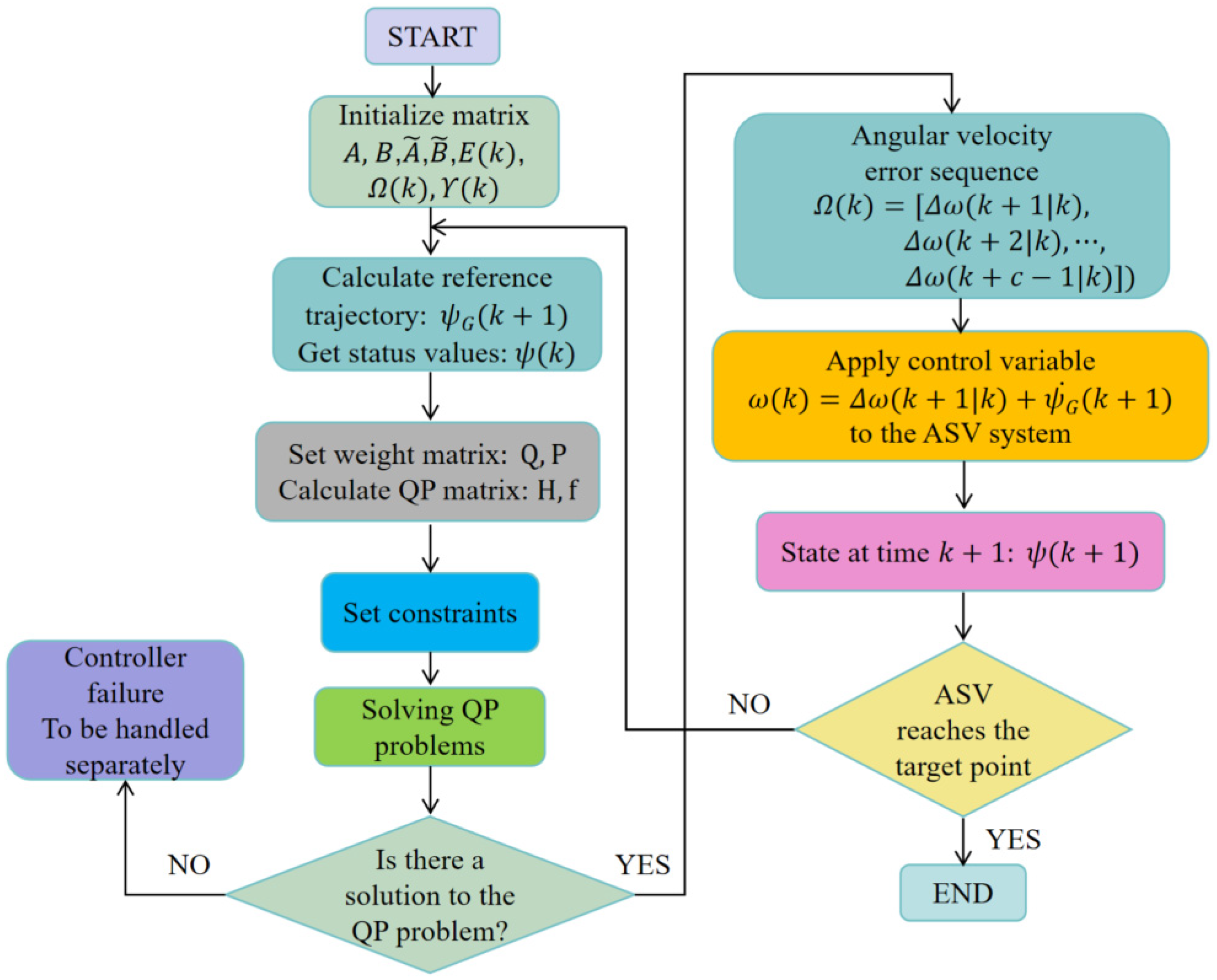
This paper proposes an angular velocity design method based on MPC to achieve the precise constraint control of angles and angular velocities. The specific implementation of MPC is shown in Figure 3. In the ASV system, due to physical limitations and safety considerations, control inputs such as heading angle ψ and angular velocity ω , as well as states like position, are typically subject to strict constraints. Compared to the methods in the literature [10,11], this paper introduces angle error e ψ G and angular velocity constraints, effectively resolving the issue of limited angles and angular velocities in practical applications, ensuring that the ASV’s directional error and angular velocity changes remain within a reasonable threshold range. Furthermore, it can predict future system states and formulate optimal control strategies accordingly, avoiding the complexity of parameter design encountered in PID controllers proposed in the literature [10,11]. This enables it to better handle delays and complex dynamics in the ASV system, thereby improving control accuracy and stability.

3.3. Controller Design

To achieve the objectives of this paper, we have designed navigation control laws based explicitly on the kinematic model (1) of the ASV, which are detailed as follows:
v = tanh K u p Λ n , e ψ G d G v m a x ω = ψ ˙ G K ω tanh e ψ G e ψ G π 4 ψ ˙ G + ω e ψ G < π 4
Here, p n , Λ is a direction error assistance function designed using a saturation function S a t Λ n , which satisfies p Λ n , ϕ = Λ n s a t Λ ( ϕ n ) Λ n . The state n and Λ represent the independent variable of the function. u = v , ω T is the linear velocity and angular velocity of ASV. K u , K ω , and v m a x are positive parameters. The constant v m a x is the maximum value of linear velocity. Additionally, d G = ( x G 2 + y G 2 ) 1 2 , which satisfies
x G = r o e x , T i = 1 N K o , i e x , O i e d e , i R o , i σ i / σ i y G = r o e y , T i = 1 N K o , i e y , O i e d e , i R o , i σ i / σ i
where error variables e x , T , e y , T , e x , O i , and e y , O i and design parameters r o , K o , i , σ i , d e , i , and R o , i are defined in the previous section.
To verify the stability of the navigation control laws, the following lemma and theorem are proposed.
Lemma 2
([25]). There exists a state z that satisfies z : 0 , R is a continuous first-order differentiable if the state x has its limit with t and   t ( 0 ,   ) is consistent and continuous, and then lim t z ˙ ( t ) = 0 .
Theorem 3.
Consider the ASV systems (1), dynamics (2), and the Gaussian BLF with elliptical obstacles (4). The control laws  v and ω in (10) can ensure that the ASV does not collide with obstacles; it also ensures that the ASV reaches the target. This is mathematically described as follows:
(1)
  t > 0 , and the variable d e , i ( x o , i , y o , i ) between the ASV and the obstacles satisfies d e , i > R o , i , where R o , i 1 is the equivalent elliptical obstacle safety distance that can predefine the obstacle.
(2)
When t , the distance d between the ASV and target point converges to zero; that is,
lim t   d = 0 ,   lim t   ( x x T ) = 0 ,   lim t   ( y y T ) = 0 .
Theorem 2 ensures precise positioning and efficient obstacle avoidance control for ASV in environments with multiple obstacles. This theorem allows the ASV to be optimized and adjusted in real time based on the time-varying reference information, enabling adaptive motion control in complex environments. Meanwhile, providing appropriate constraints for different environments firmly guarantees the stability and safety of ASV motion control, thus enabling reliable operation in practical applications.
Proof of Theorem 3.
In this module, we provide a detailed proof of Theorem 2. To verify the relevant content of Theorem 2, we take the derivative of Equation (4), and we can obtain:
V ˙ = v c o s ψ   x G v s i n ψ y G
where x G and y G are defined in Equation (11). Define d G = ( x G 2 + y G 2 ) 1 2 ; thus
V ˙ = v d G cos   e ψ G
Here, e ψ G = ψ ψ G ,   ψ G = a t a n 2 ( y G , x G ) . According to Equation (10), we can obtain e ψ G ˙ = ψ ˙ G ω , and ψ ˙ G = ( y ˙ G x G y G x ˙ G ) / ( x G 2 + y G 2 ) . Here, x ˙ G = v x s , and y ˙ G = v y s , where
x s = c o s ψ { i = 1 N [ K o , i e d e , i R o , i σ i / a 2 σ i 2 K o , i e x , O i 2 e d e , i R o , i σ i / a 4 σ i 2 ] r o } + s i n ψ 2 K o , i e x , O i e y , O i e d e , i R o , i σ i / a 2 b 2 σ i 2 }
y s = s i n ψ { i = 1 N [ K o , i e d e , i R o , i σ i / b 2 σ i 2 K o , i e y , O i 2 e d e , i R o , i σ i / b 4 σ i 2 ] r o } } + c o s ψ 2 K o , i e x , O i e y , O i e d e , i R o , i σ i / a 2 b 2 σ i 2 }
Here, error variables e x , T , e y , T , e x , O i , and e y , O i and design parameters r o , K o , i , σ i , a , b , d e , i , and R o , i are defined in the previous section.
In the process of obstacle avoidance control, it is imperative to regulate not just the distance d between the ASV and its intended target but also the spacing between the ASV and any potential obstacles. Ensuring the convergence of the state variable d G facilitates both the achievement of approaching the target and maintaining a safe distance from obstacles.
Due to the existence of the directional error auxiliary function p Λ n , e ψ G , when the ASV deviates from the desired angle ψ G by more than π / 4 , the ASV will stop and adjust its angle. In this case, if the MPC method is used to control the ASV’s heading angular ψ to track the desired angle ψ G , it may result in failure. Therefore, we will analyze and discuss the situation in two scenarios:
Case 1: When e ψ G π / 4 , we take the partial derivative with respect to e ψ G and substitute the angular velocity from the control laws (10) to obtain
e ˙ ψ G = v y G cos   ψ G x G sin   ψ G ( x G 2 + y G 2 ) 1 2 ω = K ω tanh   e ψ G
Based on the analysis in (13), it can be deduced that the directional error e ψ G and its derivative e ˙ ψ G are always opposite signs. Consequently, this indicates that lim t   e ψ G = 0 .
Case 2: When e ψ G < π / 4 , we utilize the MPC method to optimize and find the solution. According to Theorem 2, it can be concluded that e ψ G 0 .
Integrating Cases 1 and 2, it can be derived that e ψ G 0 . And by substituting the control law (10) into Equation (12), we can obtain:
V ˙ = tanh K u p Λ n , e ψ G d G v m a x d G cos   e ψ G 0
According to Theorem 1, we can obtain d e , i > R o , i . Condition (1) has been proven. According to Lemma 2, we can obtain x G , y G 0 , when t 0 . In Gaussian BLF, we can ensure that the distance from the ASV to the obstacle is always more significant than the effective repulsive field range by adjusting the repulsive field parameters. Meanwhile, to eliminate the influence of local minimum, we constrain the conditions e x , T / e y , T e x , O i / e y , O i . Therefore, we can obtain x T x 0 , y T y 0 , when t 0 . Condition (2) has been proven.
Based on the proofs of Condition (1) and Condition (2), Theorem 2 has been proven. □
Remark 4.
This paper proposes a control strategy for ASV positioning and obstacle avoidance based on Gaussian BLF, specifically considering elliptical obstacles. The specific process is illustrated in Figure 4. Similarly to the approaches in the literature [10,11], this paper introduces a direction error auxiliary function  p Λ n , ϕ = Λ n s a t Λ ( ϕ n ) Λ n . When the ASV’s heading angle ψ deviates excessively from the predetermined value (such as [ π / 4 ,   π / 4 ] ), this function triggers a control strategy that enables the system to stop and adjust its angle automatically. However, unlike the methods in the literature [10,11], we incorporate a limitation on the range of error angles e ψ G in the cost function, achieving linearization of the ASV system (12). Specifically, if the ASV’s error angles e ψ G exceeds this limit, the direction error auxiliary function p Λ n , ϕ in the linear velocity v (10) comes into play, and the ASV system automatically stops and adjusts its direction. At this point, the system (12) remains at zero. This would typically result in the failure of using MPC for constrained control of the angle error. Our approach ensures that system (12) will not have its value reduced to zero when the angle exceeds the threshold, thus preventing the risk of MPC controller failure.
It is worth noting that this paper does not simply utilize existing MPC technology but rather represents a further optimization based on it. Compared to the literature [19,20,21,22], we have combined the obstacle avoidance method using Gaussian BLF with MPC technology. By considering both positioning and obstacle avoidance requirements, we have designed an integrated desired heading angle e ψ G that incorporates the Gaussian BLF term, replacing the traditional e ψ , which only considers positioning. Utilizing MPC technology, we have designed an optimal control law to achieve error convergence, thereby addressing the complexity and design challenges of considering additional obstacle avoidance terms or constraints in the cost function design, as seen in the literature [19,20]. Additionally, compared to the literature [21,22], this paper ensures that the system designed by MPC is always a first-order linear system, effectively overcoming the limitations of complex second-order nonlinear systems in ASV.

4. Simulation Results

In this section, simulation experiments are conducted using the MATLAB/Simulink platform to evaluate the effectiveness of the obstacle avoidance control strategy based on BLF and MPC proposed in this paper. The relevant simulation parameters of ASV are shown in Table 1.
Here, [ x ( 0 ) , y ( 0 ) , ψ ( 0 ) , u ( 0 ) , ω ( 0 ) ] T are the initial conditions of the ASV’s starting position, heading angle, linear velocity, and angular velocity. In the MPC controller, the state matrix Q satisfies Q = 30 e y e ( 10 ) , and the input matrix R satisfies R = 5 e y e ( 10 ) . In the subsequent simulations, unless otherwise specified, the MPC and ASV motion parameters are shown in Table 1. It is worth noting that this paper is a further study based on the work of [11]. Therefore, this paper will not discuss the impact of relevant parameters in Table 1 on ASV.

4.1. Comprehensive Evaluation of MPC

Inspired by the literature [19,20,21,22], we employ MPC to control the ASV’s heading angle for positioning and obstacle avoidance. To verify the effectiveness of MPC, two aspects will be explored: stability and performance comparison.

4.1.1. Stability Demonstration

This section mainly analyzes the stability of MPC. In the simulation, we allow the ASV to navigate from the initial position P ( x , y ) to the target position P T ( x T , y T ) while avoiding collisions with obstacles. To make this method more convincing, here we have tested ASV’s obstacle avoidance in two different positions, as shown in Table 2.
For this part of the simulation, since we are validating the MPC, the scenario with multiple obstacles is temporarily not considered. Therefore, in the simulation, the long axis radius a and short axis radius b of the equivalent elliptical obstacle satisfy a = 2 and b = 1 , respectively. The values of the remaining parameters are the same as those in Table 1 and mentioned earlier.
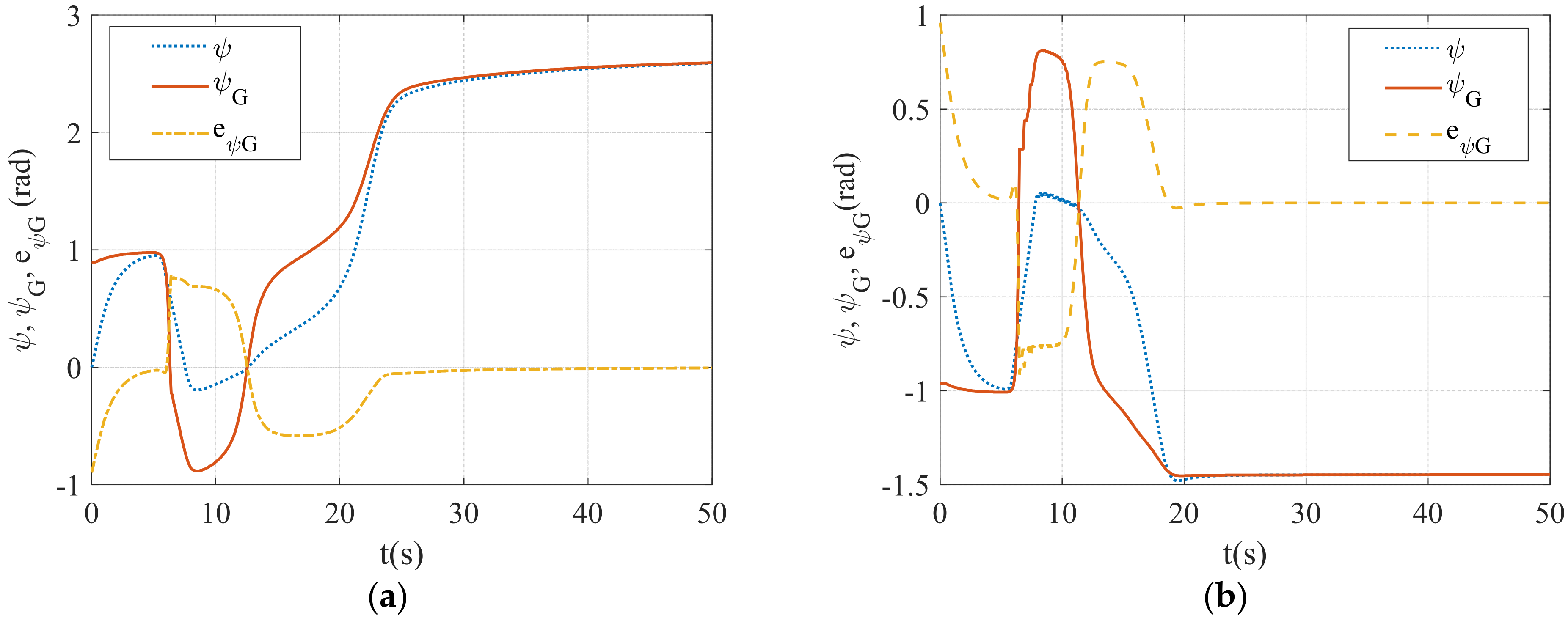
Figure 5 demonstrates the tracking capability of the ASV’s heading angle towards the desired heading angle considering elliptical obstacles under the MPC method. Specifically, Figure 5a,b represent the tracking capability under different initial positions of the ASV, obstacle position, and target position. As seen from the figures, the ASV’s heading angle gradually converges towards the desired heading angle. The error between the two ultimately tends towards zero. This effectively validates the effectiveness of the MPC method presented in this paper.

4.1.2. Performance Comparison

To verify the superiority of the MPC method proposed in this paper, this section conducts simulation comparisons with other related works. In the simulation, we allow the ASV to navigate from the initial position P ( x , y ) to the target position P T ( x T , y T ) while avoiding collisions with obstacle. The specific positional parameters are shown in Table 3.
In the simulation, the relevant parameters of the equivalent obstacle are the same as in the previous section. Additionally, the constraint conditions for MPC are:
π / 4 < ε k < π / 4 0.5 < ω k < 0.5
Here, ε k is the state vector in the MPC method, which can be used to represent the error heading angle e ψ G of the ASV in this paper, and ω k is the angular velocity of the ASV.
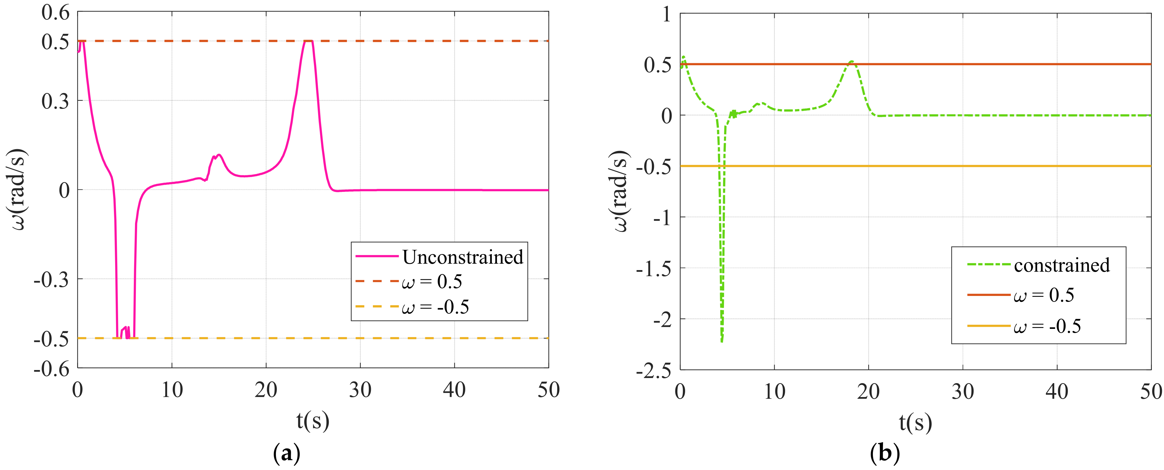
Figure 6 and Figure 7 show the variation of the heading error angle under the MPC method, considering constraints and without considering constraints. Specifically, in Figure 6, the purple curve in Figure 6a represents the heading error without constraints, while the blue curve in Figure 6b represents the heading error when considering constraints. In Figure 7, the pink curve in Figure 7a depicts the ASV angular velocity without constraints, and the green curve in Figure 7b represents the ASV angular velocity when considering constraints.
Figure 6 compares the variation of the heading error angle under two MPC methods: Figure 6a shows the convergence process of the heading error without constraints, while Figure 6b demonstrates the convergence process of the heading error with constraints. As seen in Figure 6a, although the system can ultimately converge the heading error to zero, there are fluctuations and deviations during the process. This unconstrained convergence process may lead to unnecessary energy consumption and mechanical wear and tear in ASVs in practical applications, potentially exceeding their physical limits and causing equipment damage or safety hazards. In Figure 6b, the convergence process of directional error is limited to a predetermined safety or performance boundary.
Figure 7 demonstrates the variation in angular velocity with and without constraints. Similarly to the heading error in Figure 6, the unconstrained angular velocity variation in Figure 7a leads to excessively fast or slow angular velocities when the ASV is steering or adjusting its direction. This not only affects the navigation accuracy and response speed of the ASV, but can also put unnecessary stress on its mechanical structure. However, as shown in Figure 7b, when the ASV is steering or adjusting its direction, its angular velocity is limited to a reasonable range. This not only helps improve the navigation accuracy and response speed of the ASV, but also reduces mechanical wear and extends its service life.
This constrained convergence process not only ensures the stable operation of the ASV but also reduces unnecessary fluctuations and deviations, significantly improving the navigation accuracy and overall performance of the ASV. In summary, Figure 6 and Figure 7 effectively validate the advantages of the MPC approach considering the constraints presented in this paper.

4.2. Comprehensive Evaluation of ASV Control

In this section, we combine the MPC with the elliptical obstacle model to comprehensively achieve motion control for an ASV. To verify the effectiveness of this strategy, simulation experiments will be conducted by stability and performance comparison.

4.2.1. Stability Demonstration

To verify the feasibility of the control strategy in this paper. This section analyzes ASV motion in both single obstacle and multi obstacles environments to comprehensively evaluate its practical application potential.
(1)
Obstacle Avoidance of Single Obstacle
In the simulation, we enable the ASV to navigate from the initial position P ( x , y ) to the target position P T ( x T , y T ) while avoiding collisions with obstacle P o ( x o , y o ) . And the specific positional parameters are shown in Table 4. Additionally, the relevant parameters of the equivalent obstacle and MPC are the same as in the previous section.
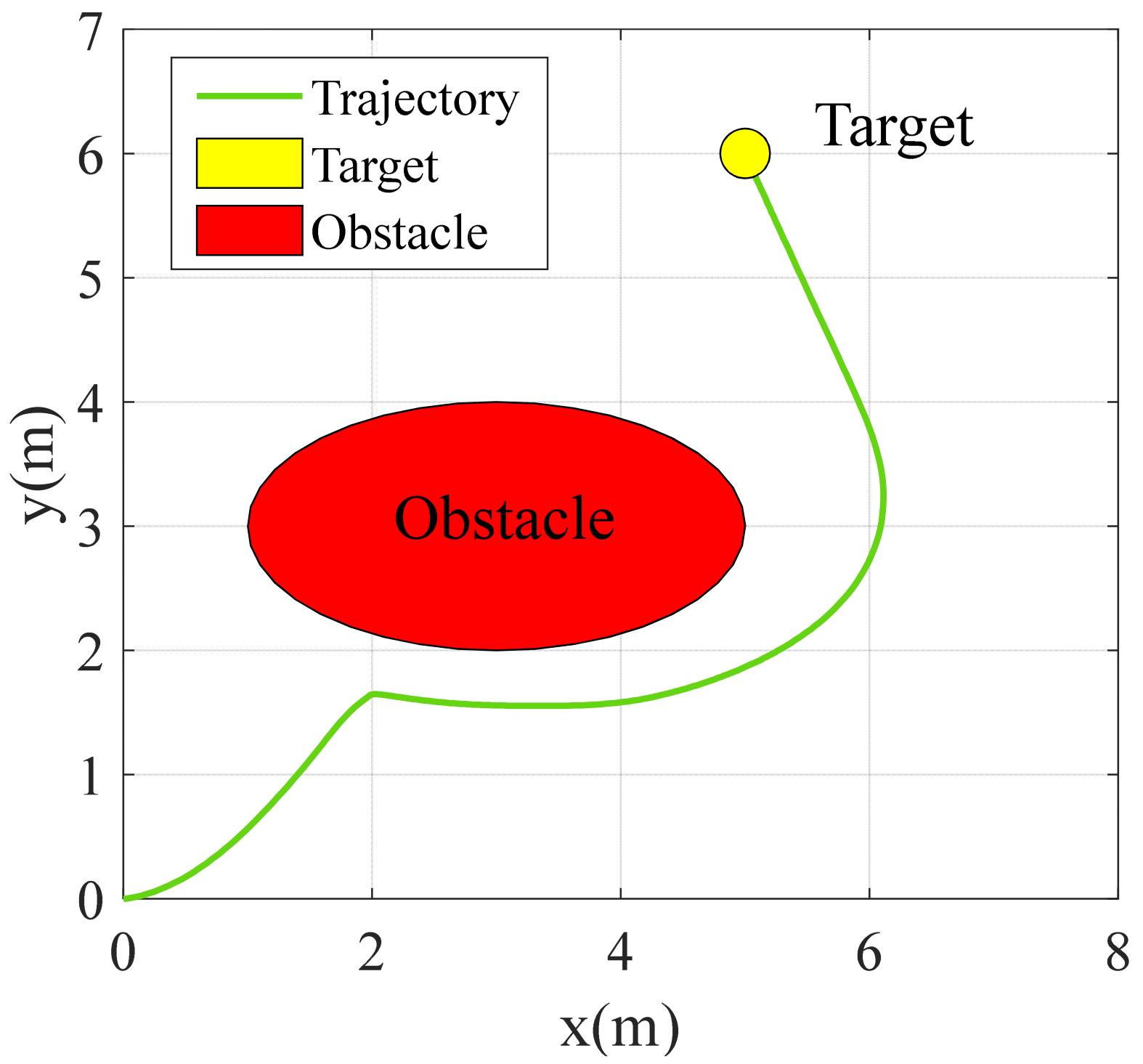
Figure 8 depicts the collision free trajectory of the ASV navigating from the initial position to the destination. As evident from the illustration, the ASV exhibits a remarkably smooth maneuver, adeptly circumventing the elliptical obstacle and subsequently arriving at the desired target. This demonstration effectively validates the efficacy of the control strategy proposed in this paper when confronted with a single obstacle.
(2)
Obstacle Avoidance of Multiple Obstacles
After verifying the feasibility of the single obstacle scenario, we conducted simulation experiments in multiple obstacle environments to further verify the feasibility of the strategy proposed in this paper.
In the simulation, we navigate the ASV from the initial position P ( x , y ) to the target position P T ( x T , y T ) with multiple obstacles P O , 1 , P O , 2 , P O , 3 , and P O , 4 . The safe distances of the four obstacles are R O , 1 , R O , 2 , R O , 3 , and R O , 4 , respectively. The detailed parameter design for the obstacles is presented in Table 5, while the remaining parameters for these obstacles remain identical to those described in the previous section.
Figure 9 depicts the trajectory of the ASV as it navigates from the initial point to the target point, avoiding four obstacles. The blue dashed line signifies the path traveled by the ASV, while the four ellipses in distinct colors represent the safety zones of each obstacle, modeled as equivalent ellipses. The small yellow circle indicates the target destination.
Figure 9 shows that the ASV completed the positioning and obstacle avoidance tasks, exhibiting a smooth and concise trajectory. This effectively validates the effectiveness of the control strategy proposed in this paper in a multi-obstacle environment.
Based on the comprehensive analysis of Figure 8 and Figure 9, the effectiveness of the control strategy presented in this paper has been validated effectively.

4.2.2. Performance Comparison

Obstacle avoidance and positioning control is achieved in the literature [11] through a simple method, and a saturation controller is introduced to realize the anti-saturation control of the robot. However, there is some difficulty using this method considering input and state constraints and it is not an optimal control. Meanwhile, the process of equivalent obstacles is rather conservative. Therefore, to thoroughly evaluate the performance of the positioning and obstacle avoidance control strategy proposed in this paper, simulation experiments are conducted to analyze the critical parameters of the ASV, including its trajectory, heading angle error, and angular velocity. Through comparative analysis, this section aims to demonstrate the advantages of the control strategy in terms of trajectory smoothness, heading control accuracy, and dynamic response capability.
To facilitate a direct comparison, the simulation for this section is conducted in a single obstacle environment. During the simulation, the relevant parameters for the MPC remain the same as those in the previous section and can be referred to in Table 1. However, the key differences lie in the respective positions of the ASV, obstacle, and target point, which are detailed in Table 6.
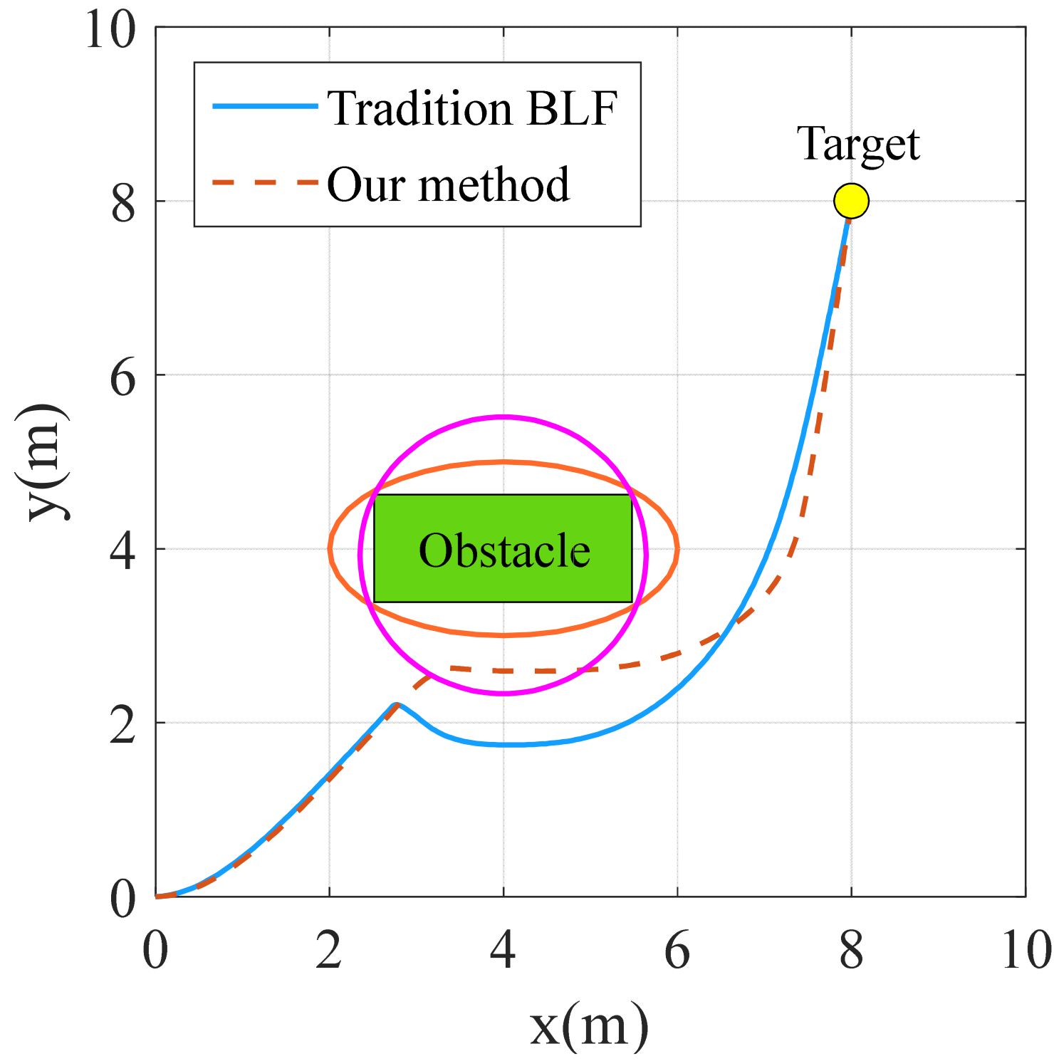
Figure 10 depicts the trajectories of the ASV under different obstacle representation methods. The orange dashed line represents the trajectory of the ASV in an environment with an equivalent elliptical obstacle domain, as proposed in this paper. The blue curve represents the trajectory obtained under the equivalent circular obstacle domain representation, as described in [11]. The green rectangle signifies the physical obstacle, while the orange ellipse indicates the equivalent obstacle range adopted in our strategy. The pink circle represents the equivalent obstacle range used in [11], and the yellow circle marks the target position.
From Figure 10, it is evident that the proposed equivalent elliptical obstacle representation method exhibits a lower level of conservatism compared to the method described in [11]. This effectively validates the advantages of the proposed elliptical equivalent obstacle representation method.
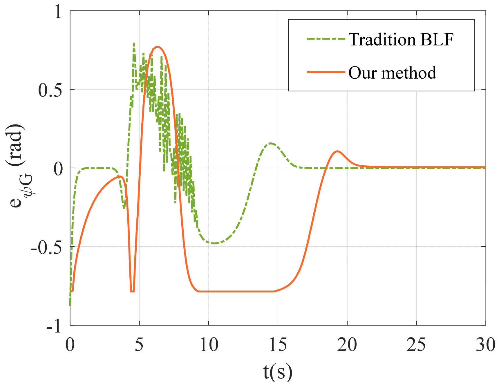
Figure 10 and Figure 11, respectively, present comparative curves for the control of angle error and angular velocity, utilizing the MPC method under the proposed control strategy and the PID method described in [11]. Specifically, in Figure 11, the orange curve represents the angle error under the MPC method proposed in this paper, while the green curve represents the angle error under the PID method from [11]. In Figure 12, the purple curve depicts the angular velocity controlled by the MPC method of this paper, and the green curve corresponds to the angular velocity controlled by the PID method from [11].
As observed in Figure 11, although the convergence speed of the proposed method is slightly slower by approximately 5 s compared to the method in [11], the fluctuation in angle error is significantly more minor, resulting in a smoother curve. This indicates a more stable and harmonious movement of the ASV, effectively validating the advantages of the proposed control strategy.
From Figure 12, it is evident that, in contrast to the method in [11], the angular velocity under the proposed method exhibits a more gradual and stable trend without sharp fluctuations. Moreover, the convergence speed is faster. This effectively confirms the superiority of the proposed control strategy.
A comprehensive analysis of Figure 10, Figure 11 and Figure 12 effectively validates the advantages of the proposed control strategy utilizing the MPC method while considering the elliptical obstacle range.
To verify the advantages of the method proposed in this paper compared with other methods, we define the potential energy index S as the basis for comparative testing. The specific design is as follows:
S = l n 0 + e ψ G 2 2 + v 2 2 + ω 2 2
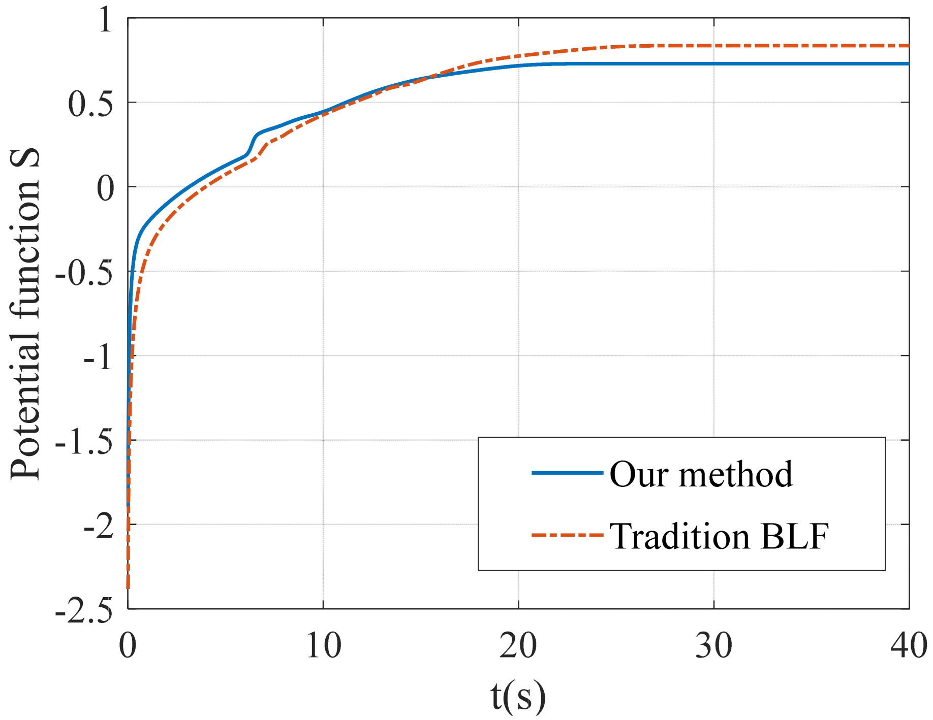
In the potential function S , the relevant variables have been given previously. Also, the parameters for simulation 13 are consistent with those in Table 1 and Table 5. Here, we introduce the l n to regulate the magnitude of the potential function, aiming to address the issue of excessive growth in the potential function values caused by the unconstrained angular velocity ω in method [11]. In contrast, our proposed strategy imposes strict limits on the angular velocity ω , ensuring that the potential function remains within a relatively reasonable range and avoiding extreme fluctuations in values. This approach not only optimizes the model stability but also makes the performance comparison between different control strategies more intuitive, thereby highlighting the superiority and effectiveness of our other control strategies.
Figure 13 represents the performance indicators of ASV under different methods. Among them, the blue dashed line represents the performance indicators of the method in the literature [11], while the orange solid line represents the performance indicators of the method proposed in this paper. As can be seen from Figure 13, the potential function S of this paper is around 0.8, while the potential function of the literature [11] is around 0.7. This effectively verifies the superiority of the method proposed in this paper.
To better replicate the operational conditions and dynamic characteristics in real-world environments, we have adjusted the simulation step size of the ASV from the original 0.01 s to 1 s. This enhancement aims to mimic the temporal scales and environmental variables that an ASV encounters during mission execution in the real world, thus ensuring the authenticity and reliability of the simulation results. By increasing the step size, we can more accurately simulate the ASV’s behavioral performance over a longer time span, including its response to external disturbances, path planning accuracy, and control strategies’ effectiveness. This will assist us in comprehensively evaluating the ASV’s performance and provide more effective guidance for its optimization in practical applications.
To avoid randomness, we conducted two sets of experimental comparisons, and the experimental data of the two sets of experiments are shown in Table 7.
Figure 14 visually presents the comparative results of different methods in the ASV potential function experiment. In this figure, the blue curve represents the potential function variation of the method proposed in the literature [11], while the orange curve reflects the potential function characteristics of the innovative method presented in this paper. Upon careful observation, it is evident that the potential function designed in this paper remains stable around a value of 1, while the potential function in the literature [11] is significantly higher, fluctuating within the range of 3–4. Given that the experimental environment closely resembles real-world scenarios, this comparative result not only effectively validates the theoretical feasibility of the control strategy presented in this paper, but also highlights its efficiency and superiority in practical operations.
The comprehensive analysis herein shows that, as shown in Table 8, compared to the literature [11], the control strategy presented in this paper has convincingly demonstrated the outstanding performance and significant advantages of the proposed method in the processes of ASV localization and obstacle avoidance. These advantages span several crucial dimensions, including the rigorous constraints on inputs and states, the optimized application of potential energy functions, and the reduced conservatism exhibited in the process of obstacle equivalent handling.

5. Conclusions and Prospects

This paper studies an ASV positioning and obstacle avoidance control method by considering the equivalent elliptical obstacle model. Firstly, in Equation (4), a novel Gaussian BLF is improved by introducing an equivalent elliptical obstacle model. In Figure 10, Figure 11 and Figure 12, we conducted a detailed comparison between the equivalent elliptical method proposed in this paper and the equivalent circular method described in [11]. Based on these simulation results, it can be observed that the method proposed in this paper exhibits significant advantages in reducing the conservatism of the equivalent obstacle. Subsequently, based on the controller in [11], we proposed an MPC-based angular constraint control strategy. Figure 5, Figure 6 and Figure 7 effectively validate the effectiveness of the method in this paper. Meanwhile, Figure 13 and Figure 14 demonstrate a significant difference in the potential function S between different methods. Specifically, the potential function of the proposed method is around 0.9, while the potential function in [11] is approximately 3–4, effectively verifying the performance advantage of the control strategy presented in this paper.
This research has attained remarkable advancements in positioning and obstacle avoidance control techniques for ASVs, particularly regarding the implementation of an equivalent elliptical obstacle model and the refinement of control strategies. However, in practical applications, overlooking the underlying dynamics model, such as the influence of uncertain disturbances and actuator dead zones, could potentially compromise the stability of ASVs. Inspired by the literature [26], in future research, we will consider issues such as disturbances and actuator dead zones in an ASV system to further enhance its performance robustness and reliability.

Author Contributions

P.Z., methodology and writing—review and editing; Y.D., software and writing—original draft preparation; S.D., resources and funding acquisition. All authors have read and agreed to the published version of the manuscript.

Funding

This research was funded by the Natural Science Foundation of Huzhou under grant 2022YZ31, and the Huzhou Key Laboratory of Intelligent Sensing and Optimal Control for Industrial Systems under grant 2022-17, Postgraduate Research and Innovation Project of Huzhou University, grant number 2024KYCX44.

Institutional Review Board Statement

Not applicable.

Informed Consent Statement

Not applicable.

Data Availability Statement

The original data contributions presented in the study are included in the article; further inquiries can be directed to the corresponding authors.

Conflicts of Interest

The authors declare no conflicts of interest.

References

  1. Ma’Arif, A.; Rahmaniar, W.; Vera, M. Artificial potential field algorithm for obstacle avoidance in uav quadrotor for dynamic environment. In Proceedings of the 2021 IEEE International Conference on Communication, Networks and Satellite (COMNETSAT), Online Conference, 17–18 July 2021; pp. 184–189. [Google Scholar]
  2. Ding, T.; Xu, K.; Ge, M. Fast fixed-time output multi-formation tracking of networked autonomous surface vehicles: A mathematical induction method. IEEE Trans. Veh. Technol. 2023, 72, 5769–5781. [Google Scholar] [CrossRef]
  3. Zhang, J.; Ma, Z.; Li, Z. Multi-UAV formation control based on a novel back-stepping approach. IEEE Trans. Veh. Technol. 2020, 69, 2437–2448. [Google Scholar] [CrossRef]
  4. Zhu, G.; Yan, J.; Zhang, P. Event-triggered adaptive neural fault-tolerant control of underactuated MSVs with input saturation. IEEE Trans. Intell. Transp. Syst. 2022, 23, 7045–7057. [Google Scholar] [CrossRef]
  5. Liu, L.; Wang, Z.; Peng, Z. Cooperative path following ring-networked under-actuated autonomous surface vehicles: Algorithms and experimental results. IEEE Trans. Cybern. 2020, 50, 1519–1529. [Google Scholar] [CrossRef] [PubMed]
  6. Ren, J.; Zhang, J.; Cui, Y. Autonomous obstacle avoidance algorithm for unmanned surface vehicles based on an improved velocity obstacle method. ISPRS Int. J. Geo-Inf. 2021, 10, 618. [Google Scholar] [CrossRef]
  7. Feng, N.; Fan, F.; Xu, G. Deep Reinforcement Learning Based AGV Self-navigation Obstacle Avoidance Method. Instrumentation 2023, 9, 11–16. [Google Scholar]
  8. Lee, D.; Woo, J. Reactive Collision Avoidance of an Unmanned Surface Vehicle through Gaussian Mixture Model-Based Online Map. J. Mar. Sci. Eng. 2022, 10, 472. [Google Scholar] [CrossRef]
  9. Khatib, O. Real-time obstacle avoidance for manipulators and mobile robots. Auton. Robot. Veh. 1986, 5, 90–98. [Google Scholar]
  10. Yang, T.; Ma, Y.; Zhang, P. Artificial potential field-based anti-saturation positioning obstacle avoidance control for wheeled robots. Nonlinear Dyn. 2022, 110, 3499–3512. [Google Scholar] [CrossRef]
  11. Zhang, P.; Ding, Y.; Chen, Y. Obstacle avoidance control of the AGV with Actuator Dead Zones Based on Fixed-time Disturbance Observers and Command Filtering. IEEE Access 2024, 66701–66716. [Google Scholar] [CrossRef]
  12. Wu, X.; Chen, H.; Chen, C. The autonomous navigation and obstacle avoidance for USVs with ANOA deep rein-forcement learning method. Knowl.-Based Syst. 2020, 196, 105201. [Google Scholar] [CrossRef]
  13. Mokhtare, Z.; Vu, M.; Mobayen, S.; Rojsiraphisal, T. An adaptive barrier function terminal sliding mode controller for partial seizure disease based on the Pinsky–Rinzel mathematical model. Mathematics 2022, 10, 2940. [Google Scholar] [CrossRef]
  14. Alattas, K.; Vu, M.; Mofid, O.; El-Sousy, F.F.; Fekih, A.; Mobayen, S. Barrier function-based nonsingular finite-time tracker for quadrotor UAVs subject to uncertainties and input constraints. Mathematics 2022, 10, 1659. [Google Scholar] [CrossRef]
  15. Singh, R.; Bera, T.; Chatti, N. A real-time obstacle avoidance and path tracking strategy for a mobile robot using machine-learning and vision-based approach. Simulation 2022, 98, 789–805. [Google Scholar] [CrossRef]
  16. Dong, Z.; Zhang, Z.; Qi, S. Autonomous cooperative formation control of underactuated USVs based on improved MPC in complex ocean environment. Ocean. Eng. 2023, 270, 113633. [Google Scholar] [CrossRef]
  17. Seal, S.; Boulet, B. Centralized MPC for home energy management with EV as mobile energy storage unit. IEEE Trans. Sustain. Energy 2023, 14, 1425–1435. [Google Scholar] [CrossRef]
  18. Benotsmane, R.; Kovács, G. Optimization of energy consumption of industrial robots using classical PID and MPC controllers. Energies 2023, 16, 3499. [Google Scholar] [CrossRef]
  19. Kim, E.; Kim, J.; Sunwoo, M.; Sunwoo, M. Model predictive control strategy for smooth path tracking of autonomous vehicles with steering actuator dynamics. Int. J. Automot. Technol. 2014, 15, 1155–1164. [Google Scholar] [CrossRef]
  20. Kokot, M.; Miklić, D.; Petrović, T. A unified MPC design approach for AGV path following. In Proceedings of the International Conference on Intelligent Robots and Systems (IROS), Kyoto, Japan, 23–27 October 2022; pp. 4789–4796. [Google Scholar]
  21. Xu, J.; Zhang, G. Tracking Control of Wheeled Mobile Robot Based on MMPC. Acad. J. Sci. Technol. 2023, 6, 137–145. [Google Scholar]
  22. Marrugo, D.; Villa, J. MPC-Based Path Tracking of a Differential-Drive Mobile Robot with Optimization for Improved Control Performance. In Workshop on Engineering Applications; Springer Nature: Cham, Switzerland, 2023; Volume 6, pp. 276–289. [Google Scholar]
  23. Fabregas, E.; Farias, G.; Aranda-Escolastico, E. Simulation and experimental results of a new control strategy for point stabilization of nonholonomic mobile robots. IEEE Trans. Ind. Electron. 2019, 67, 6679–6687. [Google Scholar] [CrossRef]
  24. Sui, S.; Zhao, T. Active disturbance rejection control for optoelectronic stabilized platform based on adaptive fuzzy sliding mode control. ISA Trans. 2022, 125, 85–98. [Google Scholar] [CrossRef]
  25. Kuhne, F.; Lages, W.; da Silva, J., Jr. Model predictive control of a mobile robot using linearization. Nonlinear Dyn. 2004, 4, 525–530. [Google Scholar]
  26. Najafi, A.; Vu, M.; Mobayen, S.; Asad, J.H.; Fekih, A. Adaptive barrier fast terminal sliding mode actuator fault tolerant control approach for quadrotor UAVs. Mathematics 2022, 10, 3009. [Google Scholar] [CrossRef]
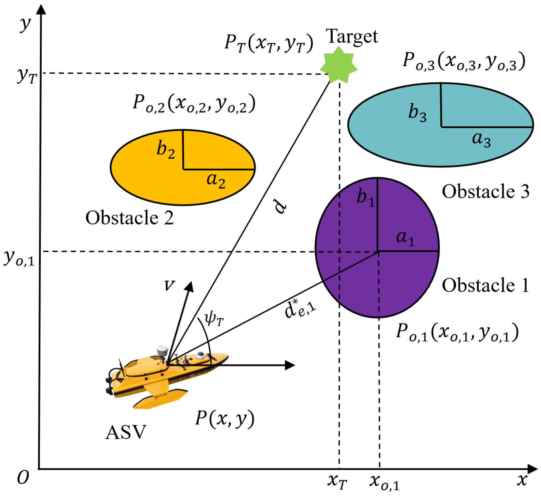
Figure 1. Schematic of ASV movement avoidance.
Jmse 12 01035 g001
Figure 2. Schematic diagram of equivalent elliptical obstacles.
Jmse 12 01035 g002
Figure 3. The flowchart of the MPC design.
Jmse 12 01035 g003
Figure 4. Schematic diagram of ASV control strategy in this paper.
Jmse 12 01035 g004
Figure 5. ASV heading angle, desired angle, and their errors: (a) Case 1; (b) Case 2.
Jmse 12 01035 g005
Figure 6. Error heading angle of MPC method: (a) error heading angle without constraints; (b) error heading angle considering constraints.
Jmse 12 01035 g006
Figure 7. ASV angular velocity of MPC method: (a) ASV angular velocity without considering constraints; (b) ASV angular velocity considering constraints.
Jmse 12 01035 g007
Figure 8. Obstacle avoidance trajectory of ASV under a single obstacle.
Jmse 12 01035 g008
Figure 9. Obstacle avoidance trajectory of ASV in a multi-obstacle environment.
Jmse 12 01035 g009
Figure 10. Comparison between equivalent elliptical obstacles and equivalent circular obstacles.
Jmse 12 01035 g010
Figure 11. Comparison of angular velocity errors between the methods in this article and [11].
Jmse 12 01035 g011
Figure 12. Comparison of angular velocity between the methods in this article and [11].
Jmse 12 01035 g012
Figure 13. Comparison of potential function S between the methods in this article and [11].
Jmse 12 01035 g013
Figure 14. Comparison of potential energy function experiments: (a) Case 1; (b) Case 2.
Jmse 12 01035 g014
Table 1. Parameters of simulation.
ParamsValueParamsValueParamsValue
x ( 0 ) 0 y ( 0 ) 0 ψ ( 0 ) 0
v ( 0 ) 0 ω ( 0 ) 0 K u 1
K ω 5 v m a x 0.5 n 2
r o 1 σ 0.25Step0.01s
p 10 c 10 T 0.2
K o 80 β 10 κ 10
Table 2. Related positional parameters in different case.
Params P o ( x o , y o ) P ( x , y ) P T ( x T , y T ) R o
Case1Value (m)(3,3)(0,0)(4,5)1
Case2Value (m)(4,4)(7,2)(0,6)1
Table 3. Related positional parameters.
Params P o ( x o , y o ) P ( x , y ) P T ( x T , y T ) R o
Value (m)(3,3)(0,0)(4,5)1
Table 4. Related positional parameters.
Params P o ( x o , y o ) P ( x , y ) P T ( x T , y T ) R o
Value (m)(3,3)(0,0)(5,6)1
Table 5. Parameters of the multiple obstacles.
Params P O , 1 P O , 2 P O , 3 P O , 4 P
Value(8,2)(3,3)(6,7)(10,6)(0,0)
Params R O , 1 R O , 2 R O , 3 R O , 4 P T
Value1m1m1m1m(9,10)
Params a 1 a 2 a 3 a 4 σ 1 , σ 2
Value 2 21 3 0.25
Params b 1 b 2 b 3 b 4 σ 3
Value 3 12 2 0.36
Params K o , 1 K o , 2 K o , 3 K o , 4 σ 4
Value1008080500.49
Table 6. Related positional parameters.
Params P o ( x o , y o ) P ( x , y ) P T ( x T , y T )
Value (m)(4,4)(0,0)(8,8)
Params a b R o
Value (m)211
Table 7. Related positional parameters.
Params P o ( x o , y o ) P ( x , y ) P T ( x T , y T ) a b
Case 1Value (m)(4,4)(0,0)(8,8)21
Case 2Value (m)(4,5)(0,0)(14,12)13
Table 8. Comparison of two control methods.
Control StrategyInput
Constraints
State
Constraints
Potential
Energy
Obstacles
Conservatism
Our methodYesYesSmallWeak
Method [11]NoNoBigStrong
Disclaimer/Publisher’s Note: The statements, opinions and data contained in all publications are solely those of the individual author(s) and contributor(s) and not of MDPI and/or the editor(s). MDPI and/or the editor(s) disclaim responsibility for any injury to people or property resulting from any ideas, methods, instructions or products referred to in the content.