Article

Assessment of a Hybrid Wind–Wave Energy Converter System in Nearshore Deployment

1
Faculty of Mechanical Engineering, Ho Chi Minh City University of Technology and Education, Ho Chi Minh City 700000, Vietnam
2
College of Technology and Design, University of Economics Ho Chi Minh City, Ho Chi Minh City 700000, Vietnam
3
School of Mechanical Engineering, University of Ulsan, 93, Deahak-ro, Nam-gu, Ulsan 44610, Republic of Korea
*
Author to whom correspondence should be addressed.
These authors contributed equally to this work.
J. Mar. Sci. Eng. 2024, 12(7), 1093; https://doi.org/10.3390/jmse12071093
Submission received: 2 May 2024 / Revised: 19 June 2024 / Accepted: 25 June 2024 / Published: 28 June 2024
(This article belongs to the Special Issue The Control, Modeling, and the Development of Wave Energy Convertors)

Abstract

:
A modeling technique for a nearshore hybrid wind–wave energy converter system (HWWECS) is presented in this research. The model consists of the buoy, wind system, and generator, allowing simulation of the HWWECS’s behavior in response to varied wave circumstances, such as different wave heights and periods. The HWWECS is made up of two buoy units and a wind system that work together to power a generator. The Wave Analysis at Massachusetts Institute of Technology (WAMIT) software is used to calculate the hydrodynamic forces. A variable inertia hydraulic flywheel is used to bring the system into resonance with incident wave frequencies in order to improve power production.

1. Introduction

Renewable energy resources offer a compelling alternative to conventional fuels due to their abundant potential, lack of pollution, and environmental friendliness [1]. As reported in [2,3,4], the development of wave energy converters (WECs) has witnessed the emergence and deployment of several technologies in real-world sea conditions. Similarly, the field of wind energy converters has been thoroughly explored, with a variety of technologies, applications, and operational devices covered [5].
A decade of research on combining offshore wind and wave energy sources has been conducted in order to most effectively utilize renewable energy supplies. Pérez-Collazo et al. [6], McTiernan et al. [7], Dong et al. [8], Ayub et al. [9], and Cao et al. [10] provide a comprehensive overview of various techniques for integrating wave and offshore wind energy. Wan et al. [11] experimentally and numerically studied the hydrodynamic responses of a combined wind and wave energy converter concept in survival modes. Dang et al. [12] developed a model for a hybrid wind–wave energy converter system. Muliawan et al. [13] analyzed the extreme responses of a combined spar-type floating wind turbine and floating wave energy converter system with survival modes. Wan et al. [14] conducted a numerical and experimental study on a combined wind and wave energy-converter concept in survival mode, focusing on water entry and exit.
Despite some encouraging improvements and possible commercial uses, the hybrid wind–wave energy converter system (HWWECS) confronts major financial and sub-structure survival issues in offshore settings. Furthermore, several researchers have explored the power performance, control strategies, and dynamic responses of integrated wind–wave energy conversion systems [15,16,17,18,19]. However, most of these studies focused on offshore deployment scenarios, which can be challenging and costly.
This research focuses on a novel conceptual design and modeling of a hybrid nearshore wind–wave energy technology. The novelty lies in the integration of a high-efficiency wave energy converter inspired by [20,21,22] with vertical axis wind turbines (VAWTs) [23,24,25] in a nearshore deployment setting. Folley et al. [20] presented an examination of the nearshore exploitable wave energy resource. As stated in [21], the mechanical power take-off (PTO) methodology is highlighted as an efficient and cost-effective method for harvesting wave energy. Following that, Binh et al. [22] reported on experimental investigations of this conceptual PTO design. VAWTs have recently gained popularity due to their lower installation costs, ease of maintenance, and ability to run regardless of wind direction. Some typical works involving aerodynamic models and analyses of straight-bladed VAWTs were presented in [23,24,25].
The proposed nearshore HWWECS concept aims to address some of the challenges associated with offshore deployment by leveraging the advantages of a nearshore location, such as easier access for maintenance and lower installation costs. Additionally, the integration of a high-efficiency wave energy converter and vertical axis wind turbines is expected to enhance the overall energy conversion efficiency and system response. In this paper, Section 2 presents the overall layout of the HWWECS. Section 3 presents the modeling approach for the WEC system, including the hydrodynamic model and the power take-off (PTO) system. Section 4 describes the modeling of the wind energy converter system, covering the vertical axis wind turbine (VAWT) aerodynamics, hydraulic circuit, and power calculations. The generator model, including the d–q axis modeling approach and the excitation and load models, is detailed in Section 5. Section 6 presents and discusses the simulation results, analyzing the performance of the proposed HWWECS under various operating conditions and phase differences between the WEC units. Finally, Section 7 concludes the paper and outlines potential future work.
The main contributions of this research can be summarized as follows:
  • A novel conceptual design for a hybrid nearshore wind–wave energy converter system, integrating a high-efficiency wave energy converter with vertical axis wind turbines.
  • A comprehensive analytical model in the time domain for the proposed HWWECS, combining the modeling of the WEC, VAWT, hydraulic system, and electric generator.
  • Numerical simulations and analysis of the HWWECS performance, including the effects of phase differences between multiple WEC units on the overall efficiency and system response.
  • Demonstration of the potential advantages of the proposed HWWECS in increasing total energy conversion efficiency and smoothing the system response by leveraging the complementary nature of wind and wave energy sources in a nearshore deployment scenario.

2. Overall Layout of the HWWECS

Figure 1 depicts the overall layout of the HWWECS, which consists of four major components: a platform, WEC units, a VAWT, and a generator. The frame structure and platform are fixed to the sea bed and kept stationary. The WEC units consisting of a floating buoy, an arm structure, a timing belt mechanism, a hydraulic flywheel, and a gearbox system are laid out in the arc to capture wave energy in different directions without diffracting on each other. A cable and pulley mechanism connects the semi-submerged floating buoy to a mass. A pulley system is secured within a frame structure and is located at the end of an arm structure to change the direction of the cable. A hinged joint and a hydraulic cylinder connect the arm construction to the frame. As a result, the hydraulic cylinder can be used to adjust the position of the arm structure to accommodate changes in water level. This system serves a dual purpose during powerful wave disturbances: it operates as a dampening mechanism to protect the structure and absorbs energy for storage in a high-pressure accumulator. To ensure safety, there is a control mechanism in place to raise the buoy above the water’s surface. The gearbox system consists of two parallel shafts rotating in opposite directions. A variable inertia hydraulic flywheel (VIHF) is attached to one end of the shaft, which houses the timing pulley. At the same time, the other end of the shaft is connected to a rotary union. The injection or withdrawal of oil into the oil chamber causes the inertia to be adjusted. The VIHF acts as an extra source of inertia, effectively modifying the floating buoy’s overall inertia. As a result, the device’s inherent frequency can be adjusted to match the incident wave frequencies. According to the principles of wave linear theory, this adjustment results in an enhanced width capture ratio. The cable manipulates the timing belt, which is engaged with the pulley, providing both pulling and pushing motions. The shaft is forced to revolve in a single direction due to the pulley’s linkage with the shaft via a one-way clutch. As a result, the pulley’s conflicting motions are turned into a uniform rotating motion of the output shaft. The vertical axis wind turbine (VAWT) is securely attached to the frame structure and is linked to the hydraulic circuit. The blades convert wind speed into mechanical energy which drives the hydraulic pump. The hose is used to supply flow to the hydraulic circuit when the hydraulic pump operates. The hydraulic motor is used to supplement the wave’s capture power in order to power the generator. The electric generator is coupled with the gearbox and the hydraulic motor to produce electricity. Moreover, the modeling of a generator prototype is carried out to simulate the complete electromechanical behavior of the proposed HWWECS.
To model the complete system behavior, individual sub-models are first developed for each component based on established theoretical formulations and then coupled together through appropriate interfaces.
The WEC unit model, described in Section 3, captures the hydrodynamic behavior of the floating buoy under wave excitation forces. This involves solving the equations of motion for the buoy in heave and surge modes, accounting for hydrodynamic forces (excitation, radiation, hydrostatic), power take-off forces, and the buoy’s inertial properties. The hydrodynamic coefficients are obtained through frequency-domain analysis using a boundary element method solver (WAMIT). The WEC model also incorporates the dynamics of the power take-off (PTO) system, including the timing belt mechanism, hydraulic flywheel, and gearbox system.
The VAWT model, detailed in Section 4, follows the conventional blade element momentum theory to estimate the aerodynamic forces acting on the turbine blades. This involves calculating the relative flow velocities, attack angles, lift and drag forces, and the resulting torque on the turbine shaft. The VAWT model is then coupled with a hydraulic circuit model that represents the hydraulic pump and motor, allowing the conversion of wind energy into hydraulic power.
The hydraulic transmission system model, also described in Section 4, captures the dynamics of the hydraulic pump driven by the VAWT, the hydraulic motor, and the associated flow rates, pressures, and efficiencies. This model provides the interface between the VAWT and the electric generator, converting the mechanical power from the wind into hydraulic power that can drive the generator.
The generator model, presented in Section 5, is based on the d–q axis modeling approach, which involves transforming the three-phase quantities (voltages, currents) into the synchronously rotating d–q reference frame. The model includes the voltage equations, electromagnetic torque calculation, and the mechanical power balance equation, allowing the simulation of the generator’s electrical and mechanical dynamics when driven by the time-varying mechanical inputs from the wind and wave energy conversion systems.
To simulate the complete HWWECS behavior, the individual sub-models are coupled through appropriate interfaces. The WEC unit model provides the mechanical power input from the wave energy conversion, which is combined with the mechanical power from the VAWT and hydraulic transmission system. This combined mechanical power then drives the generator model, producing electrical power output. The generator model, in turn, provides the electromagnetic torque feedback to the mechanical system, allowing the simulation of the dynamic interactions between the various components.
By integrating these sub-models into a unified framework, the proposed comprehensive model enables the analysis of the HWWECS’s complete electromechanical behavior, capturing the synergistic effects of the wave and wind energy inputs, as well as the dynamics of the energy conversion and transmission processes.

3. WEC System Model

In the previous work, the basic WEC hydrodynamic modeling of the buoy, which was estimated using the hydrodynamic behavior of the PTO system in conjunction with the resistive load, was carried out in [26] and verified by experimental results in [22]. Experiments were then compared with the simulation results. Based on this, a new model of WEC unit is proposed.
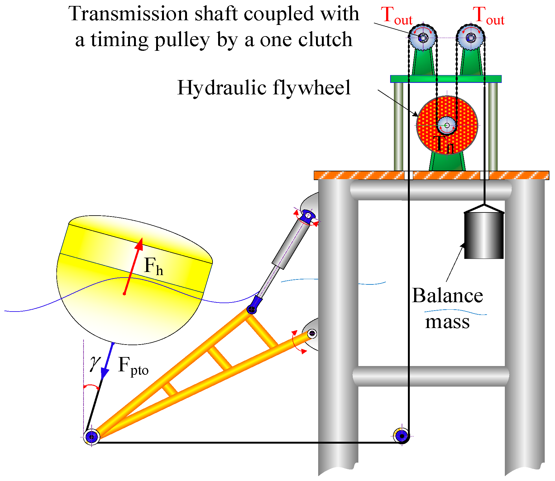
The recommended WEC unit’s specs are depicted in Figure 2. To determine the initial draft, the floating buoy is submerged by gravity and a balance mass. The VIHF supplies the supplementary inertia of the buoy which can adjust the natural frequencies. The buoy drives the transmission shaft using the timing belt and pulley mechanism. Since the shafts are coupled with the timing pulley by the one-way clutch, the shafts have only transmitted the torque in a one-way direction. Consequently, the movement of the buoy is converted into a one-way motion of the shafts.
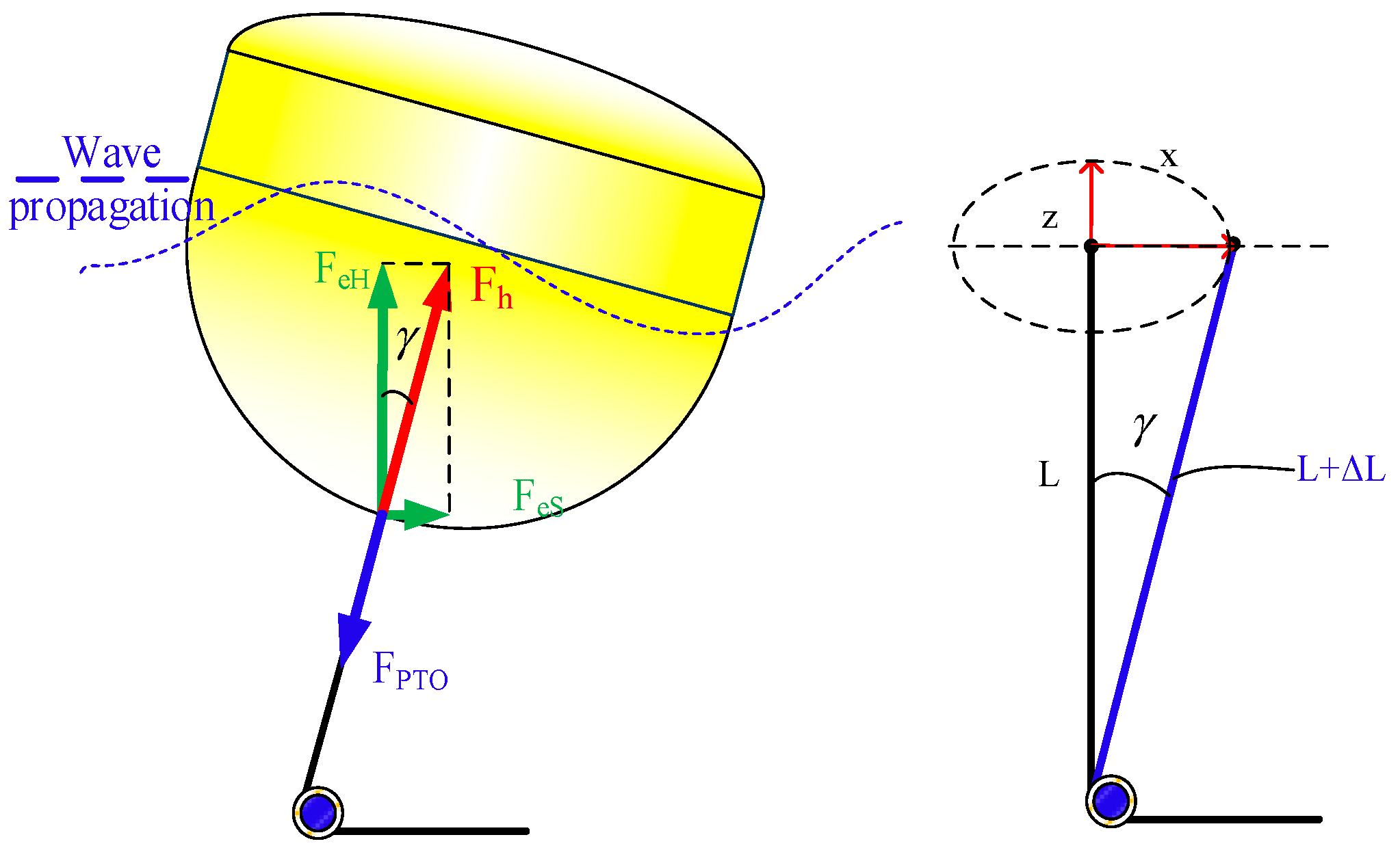
The floating buoy, which may move in both heave and surge modes, is connected to the power take-off (PTO) system via a cable, as shown in Figure 3. The mass and viscous forces operating on the cable are ignored for simplicity, allowing it to be represented as a straight line. Furthermore, pitch oscillations and rotational inertia are not taken into account in this study.
Consider x and z to be the horizontal and vertical motions of the buoy from its equilibrium location on the water surface. The red arrow indicates the positive direction. ( L + Δ L ) is the length of the cable under buoy motion, and this relationship is easily determined:
Δ L = x 2 + ( z + L ) 2 L
where γ represents the angle between the vertical direction and the cable, and it is calculated as
sin γ = x / ( L + Δ L )
The dynamics of the float are derived by solving the aforementioned equations [26,27,28]:
( M b + M a H + M s ) z ¨ = F e H + F r H + F b + F p t o cos γ
( M b + M a S + M s ) x ¨ = F e S + F r S + F p t o sin γ
Here M b , M a , and M s represent the mass of the buoy, the additional mass, and the inertia supplementary mass, respectively; F e H denotes the excitation force; F r H is the radiated force acting on the buoy in the vertical direction (heave motion); F e S is again the excitation force; F r S is the radiated force acting on the buoy in the horizontal direction (surge motion); F b represents the hydrostatic force following Archimedes’ Principle; and F p t o is the resistive force introduced by the power take-off (PTO) system [12].

4. Wind Energy Converter System

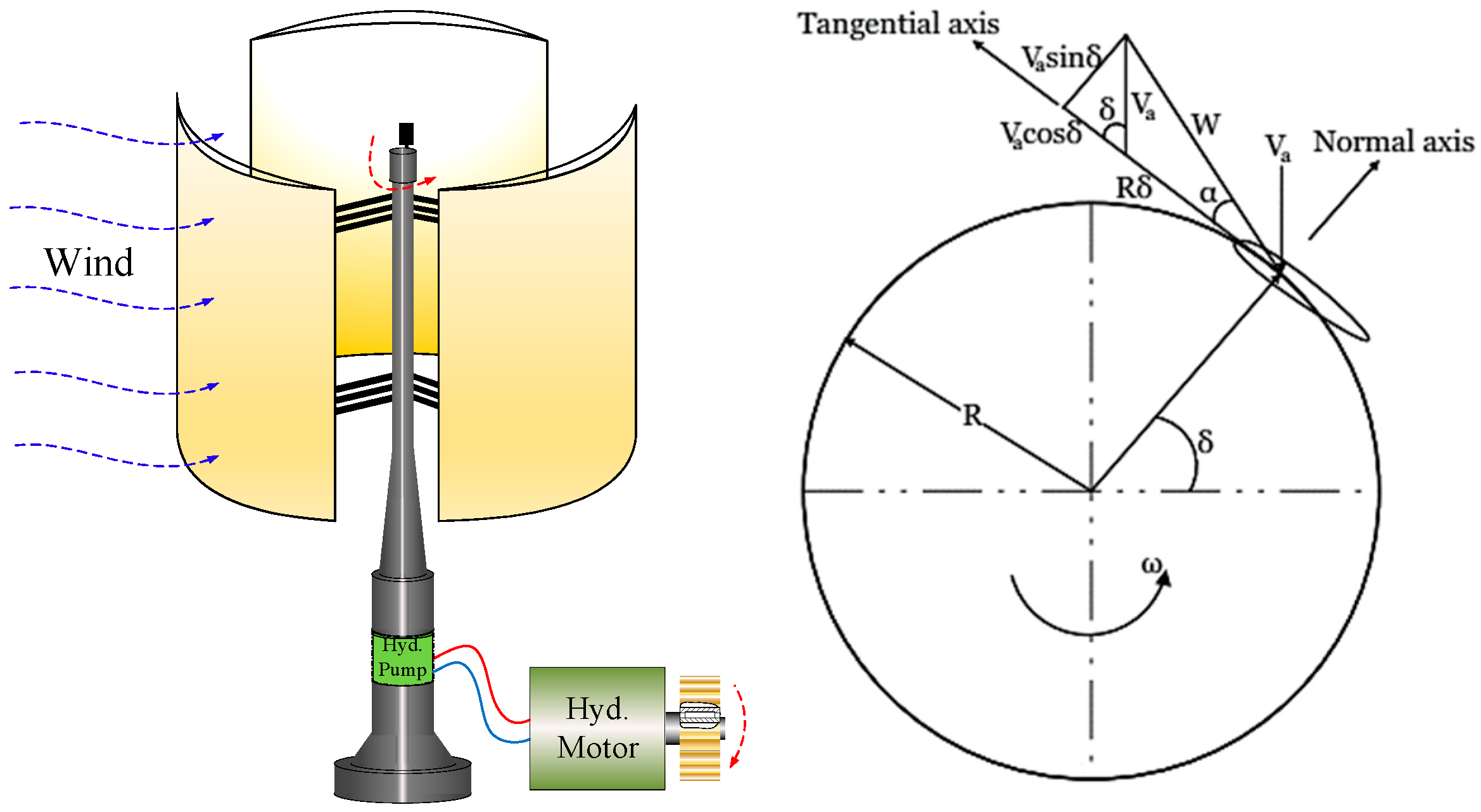
The wind energy conversion system is illustrated in Figure 4. A VAWT is employed to convert wind flow into mechanical power which drives the hydro-static transmission (HST). HST is a simple hydraulic circuit made up of two main components: the hydraulic pump and the hydraulic motor. A one-way clutch connects the hydraulic motor’s shaft to the drive gear. Consequently, reacting to the wind flow, the driving gear is transmitted to drive the generator. In order to supply the absorbed energy to the generator, the hydraulic motor speed should be optimized. When its instantaneous speed is larger than the generator speed, the absorbed energy can be taken into account to drive the generator.

4.1. Modeling of VAWT

4.1.1. The Attack Angle and Relative Flow Velocity

The flow velocities of the wind turbine are shown in Figure 4. The tangent velocity Vt and the normal velocity Vn can be expressed in the following form [23,24,25,29]:
V t = R ω t + V a cos δ
V n = V a sin δ
where ωt is the turbine‘s rotational speed, R is the radius of the wind turbine, and δ is the azimuth angle.
Then, the attack angle α can be calculated as follows [23,24,25,29]:
α = tan 1 V n V t
The relative flow velocity W is expressed as [23,24,25,29]
W = V t 2 + V n 2

4.1.2. The Tangential and Normal Forces

The relative flow velocity W, which includes two components: lift L and drag D, acts at attack angle α on the airfoil and creates an aerodynamic force on the blade. This aerodynamic force is applied in the chord and radial directions, giving the tangential force Ft and normal force Fn, respectively. The tangential and normal forces can be defined through the tangential force coefficient Ct and the normal force coefficient Cn as follows [23,24,25,29]:
F t = 0.5 C t ρ C b H w t W 2
F n = 0.5 C n ρ C b H w t W 2
where ρ is the air density, C b is the blade chord, and Hwt is the height of the turbine. Cl and Cd are lift and drag coefficients, respectively. They are dependent on the airfoil type, the Reynolds number, and the attack angle α.

4.1.3. Calculation of Torque and Power

The turbine torque is produced by only the tangential force on the blade airfoil, so the instantaneous torque of a single blade [23,24,25,29] with the radius R is determined by
Q = 0.5 C t ρ C b H w t W 2 R
For an N-blade wind turbine, each blade is separated angularly from a neighboring blade by 360/N degrees; the instantaneous torque from all N blades is determined by summing the effects of all blades at any one instant, and it is expressed in [23,24,25,29]
T w i n d = j = 1 N Q j
Then, the wind power can be calculated by multiplying the induced torque and speed of the turbine rotor in the following [23,24,25,29]:
P w i n d = T w i n d δ ˙

4.2. Hydraulic Circuit

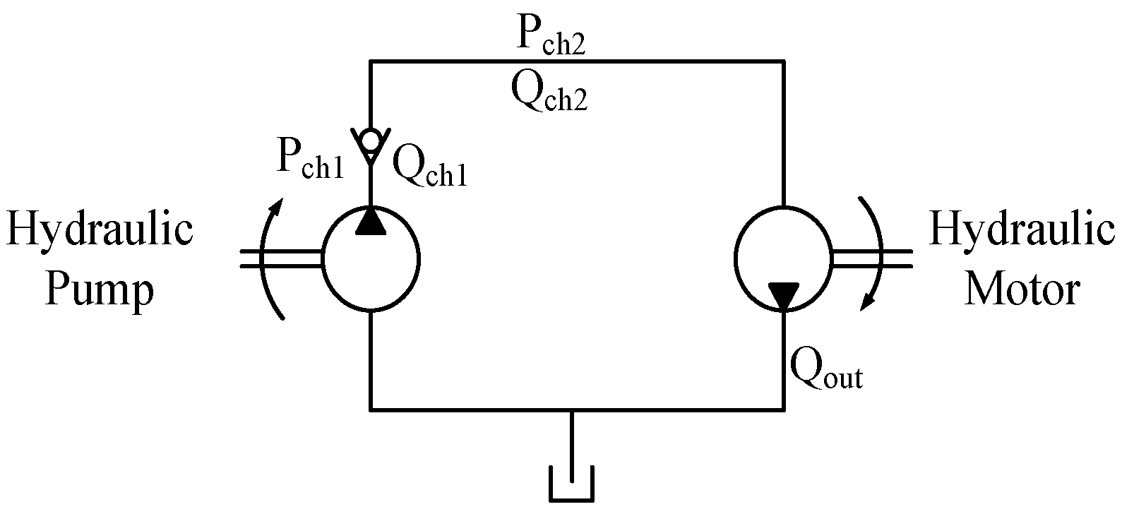
Modeling of the typical HST is carried out based on the governing equations which are given [30]. The schematic of the typical hydraulic circuit is illustrated in Figure 5. It includes a hydraulic pump coupled with the turbine rotor and the hydraulic motor is coupled with the driving gear by a one-way clutch mechanism.

4.2.1. Hydraulic Pump

Apply Newton’s second law to calculate the angular velocity for the pump shaft:
T = T w i n d T p = T w i n d P c h 1 D p 2 π η T p = I p ω ˙ p
where Twind is the torque induced by the flow of wind, D p and η T p are, respectively, the displacement and mechanical efficiency of the pump, and Ip is the total inertia moment of the pump shaft [30].
The instantaneous pressure in chamber 1 is expressed as [30]
d P c h 1 d t = β V p ( Q p Q c )
where β is the Bulk Modulus, which causes compressible fluid; V p is the volume of the pump chamber; and Q p , Q c are the pump flow rate and flow rate throughout the check valve, respectively. Here, Q p is obtained by
Q p = D p n p 1000 × η v p
where η v p is the volumetric efficiency of the pump
Q c is expressed as
Q c = Q p f o r P c h 2 < P c h 1 0 f o r o t h e r w i s e s
where P c h 2 is the instantaneous pressure in chamber 2 that can be obtained by continuity equation as follows
d P c h 2 d t = β V h ( Q c Q o u t )
where V h is the volume of the hose from the check valve to the hydraulic motor chamber; Q o u t is the flow rate throughout the hydraulic motor to return the hydraulic tank

4.2.2. Hydraulic Motor

The angular velocity of the motor shaft depends on the motor torque and the Tload and can be calculated as [30]
T = T m T e = P c h 2 D m η T m 2 π T e = I m ω ˙ m
where Im is the total inertia moment of the motor shaft (including load) (kg.m2), and Te is the electromagnetic torque induced by a rotation of the motor shaft.
Then the flow rate runs to the tank Q o u t is [30]
Q o u t = D m ω m η V m
where η V m is the volumetric efficiency of the motor.

4.2.3. Power Calculation

The input power supplied by the flow rate into the hydraulic circuit is presented in [30]:
P i H = P c h 1 Q i n
The output power supporting driving the generator is obtained by the equation [30]:
P o H = T m ω m
The efficiency of HST is obtained as follows [30]:
η H = P o H d t P i H d t
Hence, the overall efficiency of VAWT coupled with HST [30]:
η o H = P o H d t P w i n d d t

5. Generator Model

5.1. abc/dq Transformation (Park Transformation)

The generator model uses the d–q axis modeling approach, which requires transforming the three-phase quantities (voltages, currents) from the abc stationary reference frame to the synchronously rotating d–q reference frame. This transformation, known as the Park transformation [31], is given by Equation (25):
x d x q = 2 3 cos θ cos θ 2 π 3 cos θ 4 π 3 sin θ sin θ 2 π 3 sin θ 4 π 3 x a x b x c
where xd, xq are the d–q axis components, xa, xb, xc are the three-phase components, and θ = ω d t is the angle of the rotating reference frame with ω being the synchronous speed of the permanent magnet generator (PMG).

5.2. Permanent Magnet Generator

A permanent magnet generator is selected for this small-scale wave energy converter due to its high power density, low maintenance requirements, and compact size. The PMG model is developed in the rotor synchronous d–q rotating reference frame for simplicity, as shown in Figure 6.
The voltage equations in the d–q frame are [31]
v d s = R s i d s ω r L q i q s + L d d d t i d s v q s = R s i q s ω r L d i d s + ω r λ r L q d d t i q s
where vds, vqs are the d–q axis stator voltages, ids, iqs are the d–q axis stator currents, Rs is the stator resistance, λr is the rotor magnetic flux linkage, ωr is the rotor electrical speed, and Ld, Lq are the d–q axis magnetizing inductances.
The electromagnetic torque produced by the PMG is calculated as [31]
T e = 1.5 p λ r i q s L d L q i d s i q s
where p is the number of pole pairs. The torque is a function of the d–q axis currents and the rotor magnetic flux linkage.
When connected to a three-phase R-L load, the instantaneous electrical power is calculated in the following equation [31]:
P e = V a I a + V b I b + V c I c
where Va, Vb, Vc and Ia, Ib, Ic are the load phase voltages and currents, respectively.
The mechanical power driving the generator is the product of electromagnetic torque and rotor speed [31]:
P m = T e ω r
This mechanical power is provided by the combined wind and wave energy inputs after losses in the mechanical transmission system.

5.3. Excitation and Load Model

The PMG model requires representation of the source exciting the generator fields as well as the load being supplied. A constant magnetic flux linkage λr is assumed, representing the excitation provided by the permanent magnets on the rotor.
For the load, a simple 3-phase R-L load is connected to the stator windings. The per-phase load resistance R and inductance L values can be adjusted to represent different loading conditions.

5.4. Hybrid Mechanism Simulation Model

Figure 7 describes the proposed hybrid mechanism. Multiple units of HWWECS can be employed to satisfy the realistic requirement of the output power. The phase difference between these units causes the generator to perform smoothly. As shown in Figure 7, two buoys and one VAWT are employed to investigate the performance of the system. The torque generated by the buoy or hydraulic motor is considered only when the instantaneous speed of the shaft ωx (x = 1, 2), resulting from the velocity of the floating buoy or motor speed, exceeds the generator speed ωr. In instances where the supplied power surpasses the power needed to drive the flywheel, the one-way bearings disengage, meaning that the driving gear is connected to the driving shaft to propel the driven gear.
The complete generator simulation model combines the above d–q axis electromagnetic equations along with Newton’s rotational equation. Subsequently, the flywheel’s rotational motion is established by combining the driving torque and the induced generator torque as in Equation (30).
T k T e = I g ω ˙ r
where Ig is the combined inertia of the generator and coupled mechanical system, Tk is the mechanical driving torque from the wind/wave inputs after accounting for friction and windage losses, and Te is the electromagnetic torque given by Equation (27).
This allows a simulation of the electrical and mechanical dynamics of the generator system when driven by the time-varying mechanical inputs from the wind and wave energy conversion systems.
The model parameters like stator resistance, inductances, magnetic flux linkage, and inertia are based on the actual generator design specifications given in the below Section.

6. Simulation Results and Discussion

6.1. Parameters

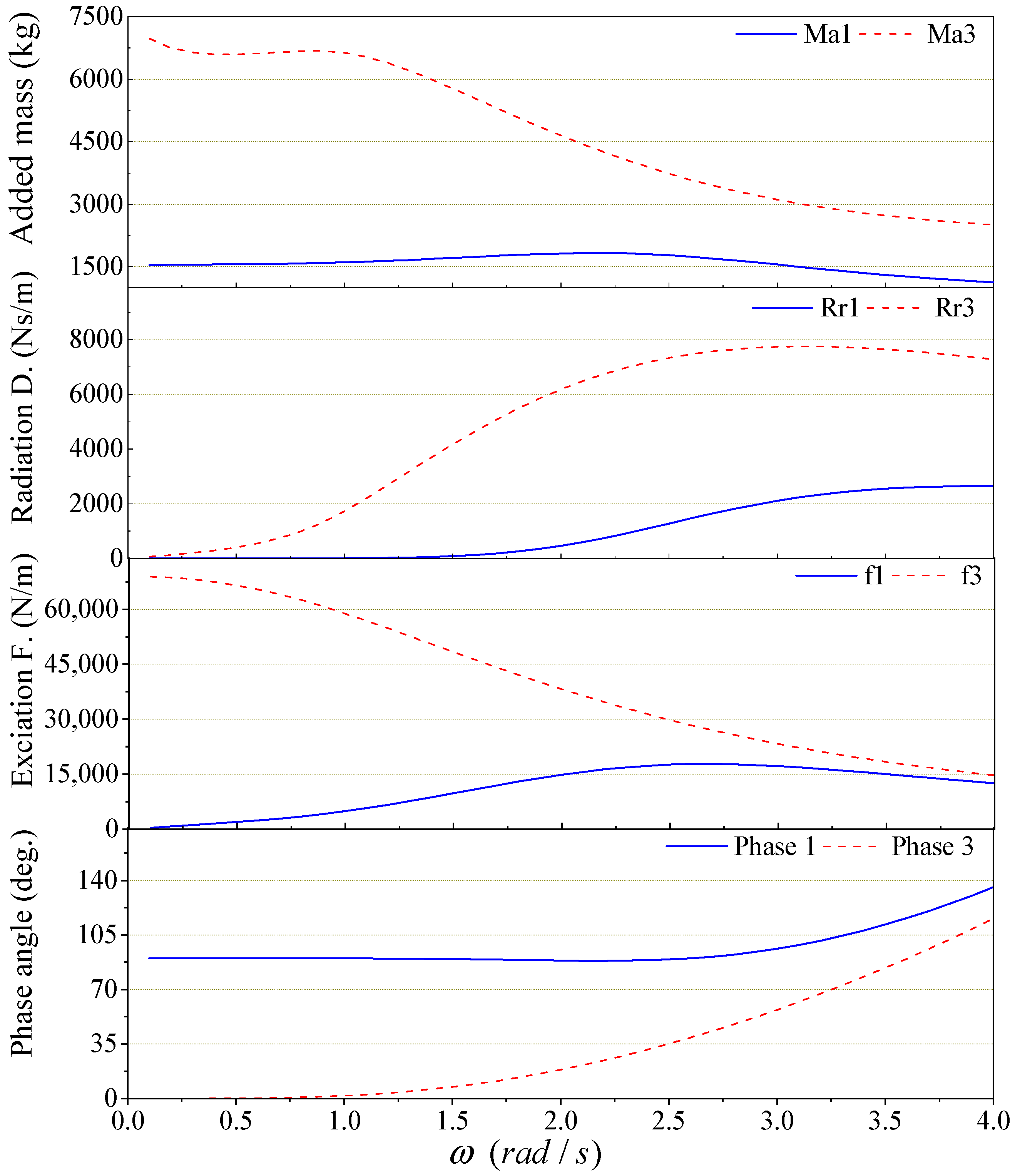
Table 1 shows some input parameters for operating circumstances, whereas Table 2, Table 3, Table 4 and Table 5 show PTO settings. The hydrodynamic parameters were obtained and plotted in the frequency domain using the given parameters, such as the buoy geometry, draft, and the aforesaid input data, as shown in Figure 8. WAMIT (version 7.0) [32] is used to compute numerical results for heave and surge modes of motion.
The variable values and system specifications used for simulating the proposed HWWECS were carefully selected to represent a realistic near-shore deployment scenario while also facilitating meaningful analysis and comparison with potential experimental studies or real-world applications.
Wave conditions: a wave height of 1.5 m and wave frequency of 2.2 rad/s were chosen to represent typical near-shore wave conditions in many coastal regions. These values fall within the operating range of the proposed WEC design and allow for an assessment of its performance under moderate wave conditions.
Water depth: a water depth of 10 m was selected, which is representative of near-shore environments and suitable for the deployment of the proposed system.
Wind speed: a wind speed of 12 m/s was chosen as it falls within the operating range of the vertical axis wind turbine (VAWT) design and allows for an evaluation of the wind energy conversion performance under moderate wind conditions.
System geometry: the dimensions of the floating buoy, arm structure, and VAWT were selected based on preliminary design considerations, ensuring a reasonable size for near-shore deployment while maximizing energy capture potential.
Hydrodynamic and aerodynamic parameters: the hydrodynamic coefficients for the WEC were obtained through frequency-domain analysis using WAMIT, a widely-used boundary element method solver. The aerodynamic parameters for the VAWT were based on established blade element momentum theory and empirical data for the chosen airfoil profile.
Hydraulic and electrical components: the specifications of the hydraulic pump, motor, and electric generator were chosen to match the expected power levels and operating conditions of the proposed system, while also reflecting commercially available components for potential real-world implementation.

6.2. Results

Simulations have been conducted to assess the performance of the HWWECS based on the provided specifications. Subsequently, simulation results under various phase differences have been analyzed to investigate their impact on the overall efficiency. Figure 9 illustrates the complete model procedure. The inputs and outputs of each part of each model such as the WEC system model, wind turbine model, wave–buoy interaction model, HST model, hybrid mechanism, and generator model are presented. The results are presented for each phase of the complete model, where the output of one phase can be correlated with the input of the other phase.
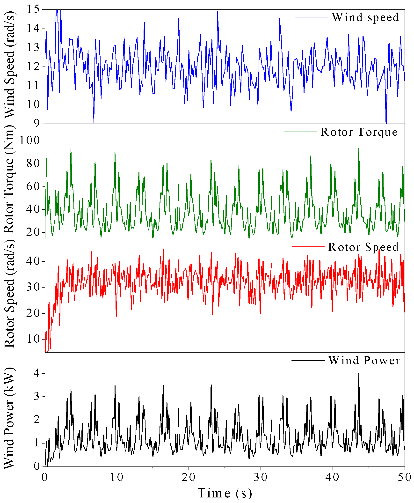
Figure 10 plots the correlation between the wind speed, rotor torque, rotor speed, and wind power. As shown in Figure 10, the top layer depicts the given wind speed which is built using Gaussian noise. Regarding the given speed, the rotor torque, rotor speed, and responding power are calculated and shown in the second layer, the third layer, and the bottom layer, respectively.
The performance of the HST is illustrated in Figure 11. Based on the wind rotor speed, the hydraulic pump generates the flow rate which is plotted in the top layer. Then, the pressure is calculated and shown in the second layer. Coupled with the resistive torque from the generator, the induced torque and speed of the hydraulic motor are derived and described in the third and bottom layers, respectively.
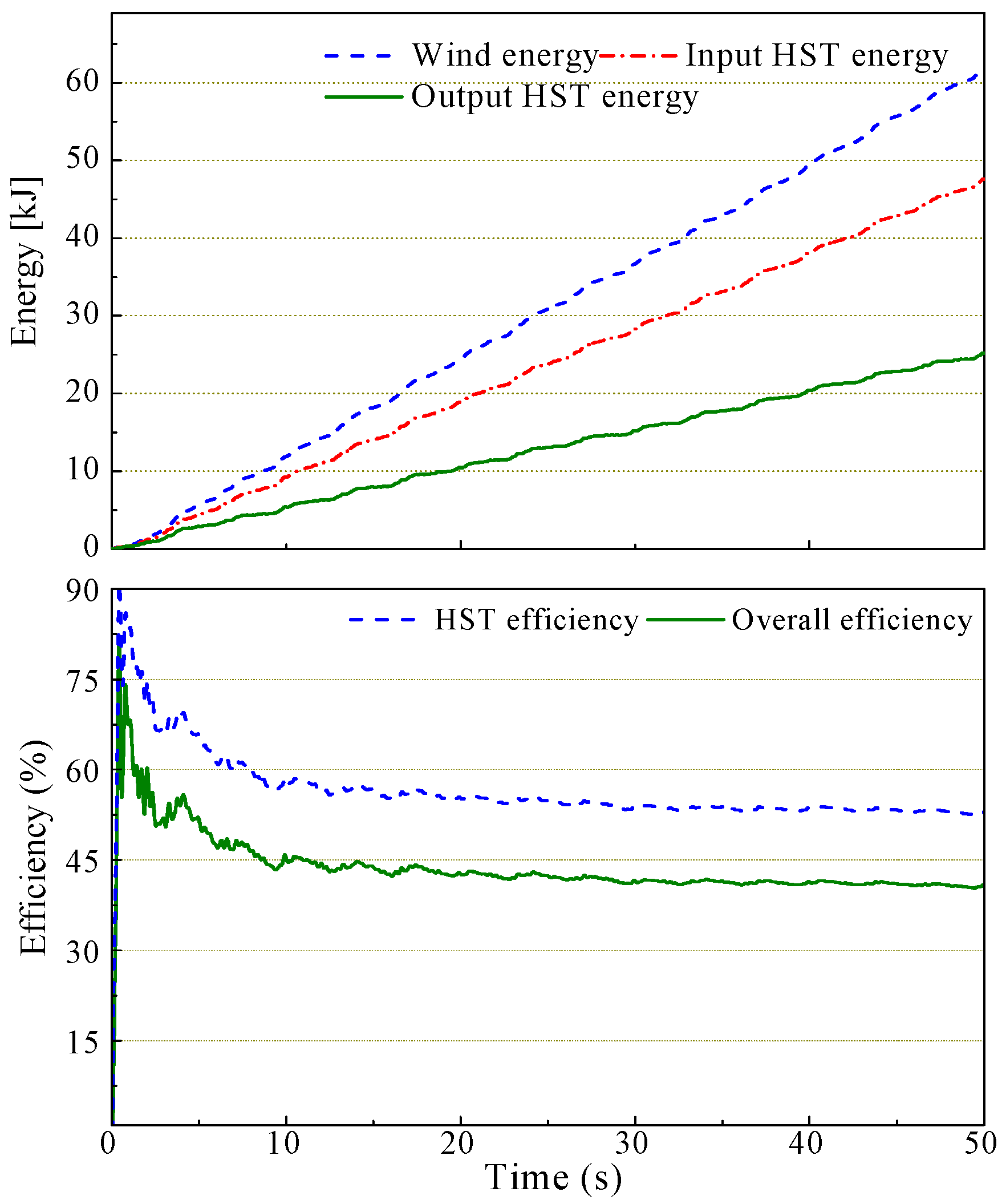
Figure 12 presents the conversion energy and efficiency of the VAWT using the HST. The driving energy calculated from the wind power is plotted on the top layer. To investigate the performance, the input HST energy, due to the flow rate and pressure, and the output HST energy, due to the torque and speed are also calculated and plotted in this layer. Subsequently, the HST efficiency, defined as the ratio of the output HST energy to the input HST energy, and the overall efficiency, defined as the ratio of the output energy to the wind energy, are illustrated in the lower layers.
Figure 13 presents a performance comparison between two floats. The heave z(t) and the surge x(t) oscillations are depicted in the first and second layers, respectively. Subsequently, the variations in cable length and the cable vertical angle are computed and displayed in the third and last layers.
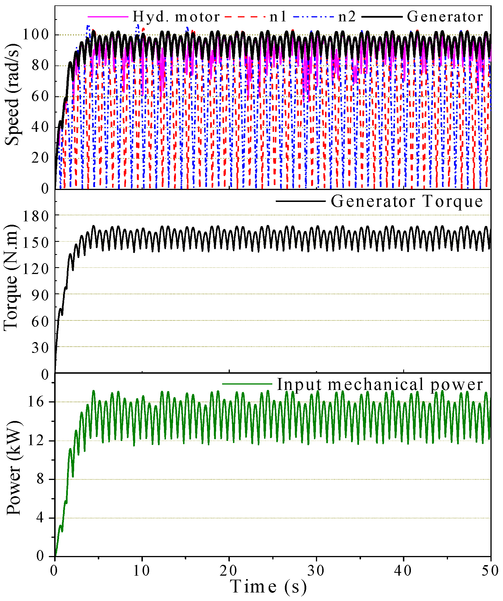
Figure 14 illustrates the mechanical behavior of the hybrid mechanism. As shown in the top layer, the speed of the hydraulic pump, the driving shafts of WEC 1, the driving shafts of WEC 2, and the generator are compared to investigate the response of the hybrid mechanism. Since the generator is driven by the co-working of the driving shafts and the hydraulic motor, the generator speed is usually higher than with the use of them independently. Therefore, the generator speed is increased, and the performance is smooth. Next, the torque induced by the generator is shown in the second layer. Based on the induced generator torque and speed, the input mechanical power driving the generator is obtained and depicted on the bottom layer.
Figure 15 shows the performance of the generator. The generating currents and voltages of the three phases are plotted in the first and second layers, respectively. Then, the output electric power is calculated and presented in the bottom layer.
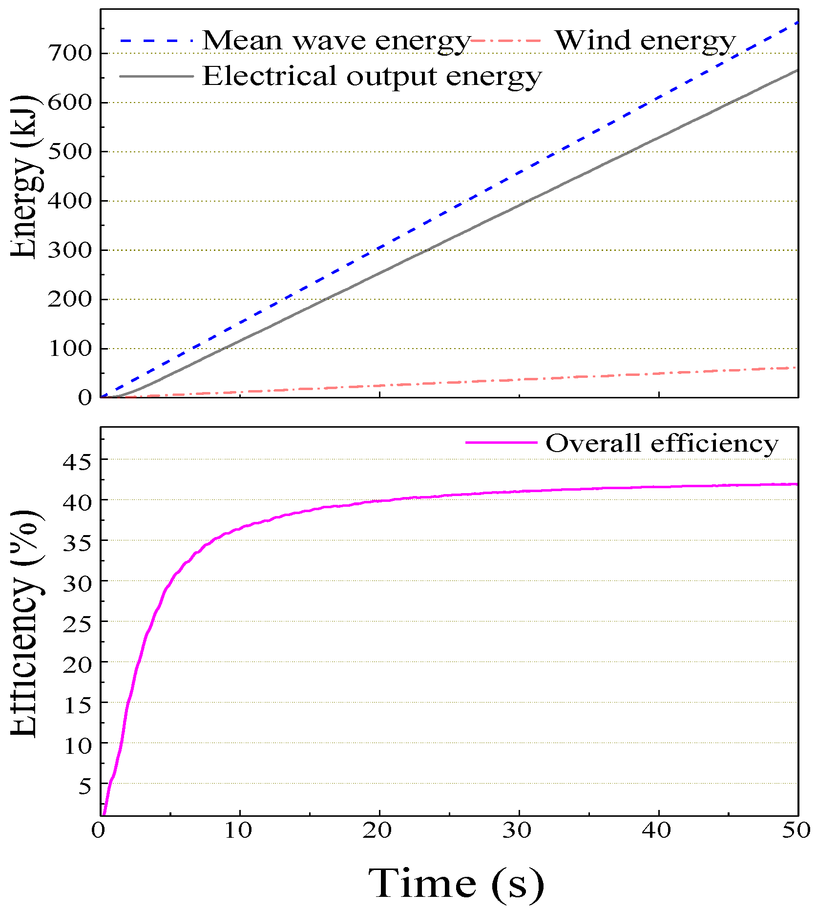
Figure 16 illustrates a comparison of the conversion energy and overall efficiency of the proposed hybrid system. Given the incident wave and buoy specifications, the mean wave energy is computed and depicted in the top layer. The input wind energy and the output electrical energy are also graphed in this layer. Subsequently, the overall efficiency of the proposed HWWECS is determined and presented in the bottom layer. In the simulation results, the overall efficiency of the proposed HWWECS is shown to reach 41.5%. This efficiency is calculated as the ratio of the output electrical energy to the combined input wave and wind energy. To benchmark this efficiency, we can consider the performance of separate stand-alone systems:
Stand-alone WEC: based on the literature, the efficiency of wave energy converters typically ranges from 20% to 35% [21,22]. The high end of this range is achieved by highly optimized WEC designs under ideal wave conditions.
Stand-alone wind turbine: The efficiency of wind turbines varies with wind speed but typically falls within the range of 30% to 45% for modern horizontal-axis and vertical-axis wind turbines [7,8,9,10].
By combining the wave and wind energy inputs in the proposed HWWECS, the simulated overall efficiency of 41.5% surpasses the typical efficiency ranges of separate stand-alone systems. This indicates that the synergistic combination of wave and wind energy sources can potentially lead to higher overall energy conversion efficiency compared with employing these sources individually.
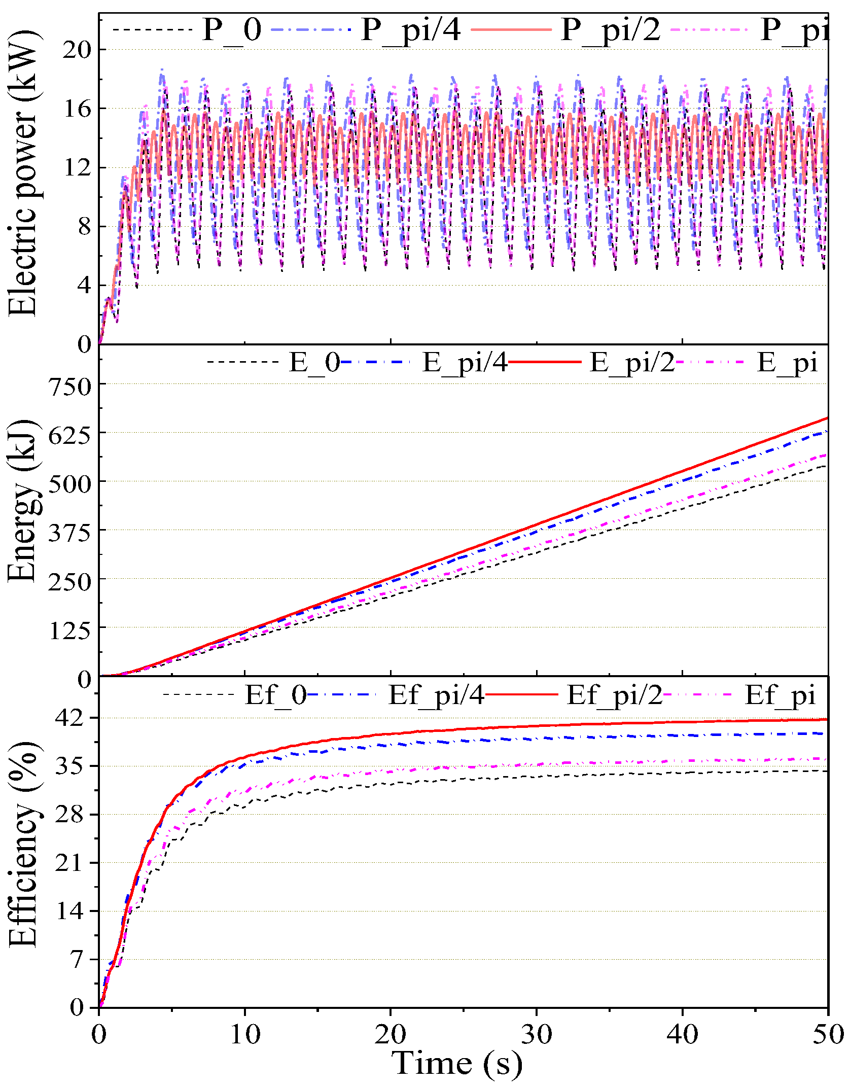
To explore the impact of the phase difference between the two buoys on the performance of the HWWECS, Figure 17 shows the time series for the output electric power, energy, and total efficiency. It is indicated that the ideal phase difference is at π / 2 . Once one buoy stops at the changing direction point, another has maximum velocity at the equilibrium position to drive the generator continuously, as shown in Figure 14 (on the top layer). When the phase difference is smaller or greater than π / 2 , the performance is more varied. In particular, when it is near the same phase or in phase with each other, the response is more varied and the efficiency is also decreased significantly.
In contrast, a stand-alone WEC or wind turbine system would exhibit more significant fluctuations in power output due to the intermittent nature of the individual energy source. The incorporation of multiple WEC units with optimal phase differences in the HWWECS helps to mitigate these fluctuations, resulting in a smoother overall system response.
Furthermore, the simulations indicate that when the phase difference deviates significantly from the optimal value (e.g., when the two WEC units are nearly in phase), the system response becomes more variable, and the total efficiency decreases. This highlights the importance of proper phase synchronization between the WEC units to fully realize the advantages of the proposed HWWECS concept.
In summary, the simulation results and comparisons against separate stand-alone systems provide evidence that the proposed HWWECS can potentially achieve higher overall energy conversion efficiency and a smoother system response by leveraging the complementary nature of wave and wind energy sources and optimizing the phase differences between multiple WEC units.
It is important to note that these conclusions are based on the simulation results and the specific system configurations and operating conditions considered in this study. Further validation through experimental studies or real-world deployments would be beneficial to confirm these advantages and refine the modeling approach if necessary.
Figure 9. Diagram of the different phases of the complete analytical model.
Jmse 12 01093 g009
Figure 10. Time Domain Analysis (TDA) results: time series of wind speed, rotor torque, rotor speed, and wind power.
Jmse 12 01093 g010
Figure 11. TDA results: time series of flow rate, pressure, torque, and speed of the hydraulic motor.
Jmse 12 01093 g011
Figure 12. TDA results: Energy and Efficiency of the VAWT coupled with the HST.
Jmse 12 01093 g012
Figure 13. TDA results: time series of the heave and surge displacements, length variation in the cable, and the vertical angle.
Jmse 12 01093 g013
Figure 14. TDA results: time series of speed for hydraulic motor, shaft 1, shaft 2, generator driving torque, and input power.
Jmse 12 01093 g014
Figure 15. TDA results: time series of current, voltage, and output electrical power.
Jmse 12 01093 g015
Figure 16. TDA results: time series of the mean wave energy, the wind energy, the output electrical energy, and the overall efficiency.
Jmse 12 01093 g016
Figure 17. TDA results: the output electric power, the energy, and the total efficiency under the different phases.
Jmse 12 01093 g017

6.3. Challenges and Limitations

6.3.1. Challenges

During the model development and testing, the challenges encountered can be identified as follows:
Coupling of multiple physics domains: one of the primary challenges in developing the comprehensive model for the HWWECS was the need to couple multiple physics domains, including hydrodynamics, aerodynamics, hydraulics, and electromechanics. Ensuring consistent interfacing and accurate information exchange between these diverse sub-models required careful formulation and implementation.
Nonlinear system dynamics: the proposed system exhibits nonlinear dynamics due to the complex interactions between the wave energy converter (WEC), vertical axis wind turbine (VAWT), hydraulic transmission, and generator components. Capturing these nonlinearities accurately while maintaining numerical stability and computational efficiency posed a significant challenge during model development and testing.
Validation and experimental data: while the individual sub-models are based on well-established theoretical frameworks, the lack of experimental data specifically for the proposed hybrid system configuration made it challenging to validate the complete system model thoroughly. Conducting scaled experiments or obtaining field data from a prototype deployment would be beneficial for model validation and refinement.
Optimization and control strategies: the proposed HWWECS offers potential for optimization and advanced control strategies to maximize energy capture and efficiency. However, the development and implementation of such strategies were beyond the scope of this initial modeling effort and could be explored in future work.

6.3.2. Limitations

The VAWT model employed in this study is based on the steady-state blade element momentum theory (BEMT), which makes several simplifying assumptions. While these assumptions are widely adopted in the initial design and analysis stages of VAWT systems, it is important to acknowledge their limitations and discuss their potential impact on the accuracy of the results. One of the key assumptions in the steady-state BEMT is that the flow field around the VAWT blades is time-invariant and can be treated as a series of independent steady-state conditions. This assumption neglects the inherent unsteady nature of the aerodynamic forces acting on the blades, which arise due to the periodic variation in blade velocities and angles of attack as the turbine rotates. The unsteady aerodynamic effects, such as dynamic stall and vortex shedding, can significantly influence the blade forces, power output, and overall performance of the VAWT, particularly at low tip-speed ratios and high angles of attack [33,34]. Furthermore, the steady-state BEMT assumes that the flow remains attached to the blade surfaces and that the blade loading is uniform along the span. In reality, flow separation and three-dimensional effects can lead to non-uniform loading distributions and localized stall regions, which are not captured by the simplified BEMT model [35,36].
Despite these limitations, the steady-state BEMT is widely used in the initial design and performance estimation stages of VAWT systems due to its computational efficiency and the availability of empirical data for lift and drag coefficients. The model provides a reasonably accurate estimate of the overall power output and torque characteristics, particularly in the optimal operating regime of the VAWT [33,37]. However, it is important to note that the results obtained from the steady-state BEMT should be interpreted with caution, especially when operating conditions deviate significantly from the design point or when highly accurate predictions of transient behavior are required.
To address the limitations of the steady-state BEMT and capture the unsteady aerodynamic effects more accurately, future work could incorporate more advanced unsteady aerodynamic models, such as the dynamic stall models [38,39] or computational fluid dynamics (CFD) simulations [40,41]. These approaches, although computationally more intensive, can provide a more realistic representation of the VAWT performance under a wide range of operating conditions and can account for the impact of unsteady flow phenomena.
In the current WEC system model, we have made the simplifying assumption of neglecting the rotational degrees of freedom and torque losses in the analysis. While this facilitates a more tractable analytical formulation, it is also important to point out its limitations and the potential impact on the accuracy of the results, particularly with regard to the energy transfer between different degrees of freedom.
By neglecting the rotational degrees of freedom, such as pitch and roll motions, the model does not account for the coupling effects between these modes and the translational motions (heave and surge). In reality, the floating buoy’s dynamics involve a complex interplay between all six degrees of freedom, and the energy transfer between these modes can significantly influence the overall system behavior and power capture efficiency [27,42].
Furthermore, the assumption of neglecting torque losses in the system implies that all the mechanical energy generated by the buoy’s oscillatory motion is efficiently transferred to the power take-off (PTO) system without any dissipative losses. However, in practical scenarios, various sources of torque losses, such as friction in bearings, seals, and transmission components (both mechanical and hydraulic), can lead to a reduction in the overall energy conversion efficiency.
To improve the accuracy of the WEC system model and better capture the energy transfer between different degrees of freedom, future work could incorporate a more comprehensive multi-body dynamics approach, where the buoy is modeled as a rigid body with six degrees of freedom [43]. This would enable the consideration of coupling effects between translational and rotational motions. Additionally, the inclusion of torque loss models, which account for various sources of dissipative losses in the mechanical and hydraulic transmission system, could provide a more realistic estimate of the overall energy conversion efficiency.

7. Conclusions

A novel conceptual design for the HWWECS has been introduced. A comprehensive analytical model in the time domain for the proposed HWWECS was developed to scrutinize its performance. The chosen variable values and system specifications are intended to represent a realistic near-shore deployment scenario, making it suitable for potential experimental studies or real-world applications in coastal regions with similar environmental conditions. Near-shore environments offer several advantages over offshore locations, including easier access for maintenance, lower installation and operational costs, and reduced exposure to extreme ocean conditions. The proposed HWWECS concept leverages these advantages by targeting deployment in near-shore areas, where the selected wave and wind conditions are representative of many coastal regions globally. Moreover, the system dimensions and component specifications were chosen to strike a balance between maximizing energy capture potential and ensuring practical feasibility for construction and deployment. The use of established modeling techniques, such as boundary element methods and blade element momentum theory, ensures that the simulation results are grounded in well-validated theoretical frameworks. Numerical results indicated that the overall efficiency was increased significantly due to the optimal phase difference between the WEC units. An overall efficiency of 41.5% has been reached.
Apparently, the proposed HWWECS has shown its advantage in increasing the total efficiency and response of the system. The performance of the proposed system is strongly dependent on the phase difference, which can be optimized by employing more WEC units and arranged in different phases to each other. While the current simulations focus on regular wave conditions for simplicity, future work could extend the analysis to irregular wave scenarios, which would better represent real-world conditions and further validate the system’s performance. In order to investigate the applicability of the proposed HWWECS, future works are going to focus on controlling supplementary inertia to adapt to irregular wave frequencies. The test rig is fabricated to apply optimization control strategies to increase the capture width ratio.

Author Contributions

Conceptualization, P.C.B. and T.D.D.; methodology, P.C.B. and T.D.D.; software, P.C.B. and T.D.D.; validation, P.C.B. and T.D.D.; formal analysis, P.C.B. and T.D.D.; investigation, P.C.B. and T.D.D.; resources, P.C.B. and T.D.D.; data curation, P.C.B. and T.D.D.; writing—original draft preparation, P.C.B. and T.D.D.; writing—review and editing, P.C.B. and T.D.D.; visualization, P.C.B. and T.D.D.; supervision, K.K.A.; project administration, K.K.A.; funding acquisition, K.K.A. All authors have read and agreed to the published version of the manuscript.

Funding

This research was supported by Regional Innovation Strategy (RIS) through the National Research Foundation of Korea (NRF) funded by the Ministry of Education (MOE) (2021RIS-003) and by University of Economics Ho Chi Minh City, Vietnam.

Institutional Review Board Statement

Not applicable.

Informed Consent Statement

Not applicable.

Data Availability Statement

Data are contained within the article.

Acknowledgments

The authors appreciate the support from the University of Economics Ho Chi Minh City, Vietnam and Ho Chi Minh City University of Technology and Education.

Conflicts of Interest

The authors declare no conflicts of interest.

References

  1. Jebaselvi, G.D.A.; Paramasivam, S. Analysis on renewable energy systems. Renew. Sustain. Energy Rev. 2013, 28, 625–634. [Google Scholar] [CrossRef]
  2. Falnes, J. A review of wave-energy extraction. Mar. Struct. 2007, 20, 185–201. [Google Scholar] [CrossRef]
  3. Falcão, A.F.d.O. Wave energy utilization: A review of the technologies. Renew. Sustain. Energy Rev. 2009, 14, 899–918. [Google Scholar] [CrossRef]
  4. López, I.; Andreu, J.; Ceballos, S.; de Alegría, I.M.; Kortabarria, I. Review of wave energy technologies and the necessary power-equipment. Renew. Sustain. Energy Rev. 2013, 27, 413–434. [Google Scholar] [CrossRef]
  5. Kumar, Y.; Ringenberg, J.; Depuru, S.S.; Devabhaktuni, V.K.; Lee, J.W.; Nikolaidis, E.; Andersen, B.; Afjeh, A. Wind energy: Trends and enabling technologies. Renew. Sustain. Energy Rev. 2015, 53, 209–224. [Google Scholar] [CrossRef]
  6. Pérez-Collazo, C.; Greaves, D.; Iglesias, G. A review of combined wave and offshore wind energy. Renew. Sustain. Energy Rev. 2014, 42, 141–153. [Google Scholar] [CrossRef]
  7. McTiernan, K.L.; Sharman, K.T. Review of Hybrid Offshore Wind and Wave Energy Systems. J. Phys. Conf. Ser. 2020, 1452, 12016. [Google Scholar] [CrossRef]
  8. Dong, X.; Li, Y.; Li, D.; Cao, F.; Jiang, X.; Shi, H. A state-of-the-art review of the hybrid wind-wave energy converter. Prog. Energy 2022, 4, 042004. [Google Scholar] [CrossRef]
  9. Ayub, M.W.; Hamza, A.; Aggidis, G.A.; Ma, X. A Review of Power Co-Generation Technologies from Hybrid Offshore Wind and Wave Energy. Energies 2023, 16, 550. [Google Scholar] [CrossRef]
  10. Cao, F.; Yu, M.; Liu, B.; Wei, Z.; Xue, L.; Han, M.; Shi, H. Progress of Combined Wind and Wave Energy Harvesting Devices and Related Coupling Simulation Techniques. J. Mar. Sci. Eng. 2023, 11, 212. [Google Scholar] [CrossRef]
  11. Wan, L.; Gao, Z.; Moan, T. Experimental and numerical study of hydrodynamic responses of a combined wind and wave energy converter concept in survival modes. Coast. Eng. 2015, 104, 151–169. [Google Scholar] [CrossRef]
  12. Dang, T.D.; Phan, C.B.; Truong HV, A.; Le, C.D.; Nguyen, M.T.; Ahn, K.K. A study on modeling of a hybrid wind wave energy converter system. In Proceedings of the 2016 16th International Conference on Control, Automation and Systems (ICCAS), Gyeongju, Republic of Korea, 16–19 October 2016; pp. 182–187. [Google Scholar]
  13. Muliawan, M.J.; Karimirad, M.; Gao, Z.; Moan, T. Extreme responses of a combined spar-type floating wind turbine and floating wave energy converter (STC) system with survival modes. Ocean Eng. 2013, 65, 71–82. [Google Scholar] [CrossRef]
  14. Wan, L.; Greco, M.; Lugni, C.; Gao, Z.; Moan, T. A combined wind and wave energy-converter concept in survival mode: Numerical and experimental study in regular waves with a focus on water entry and exit. Appl. Ocean Res. 2017, 63, 200–216. [Google Scholar] [CrossRef]
  15. Homayoun, E.; Ghassemi, H.; Ghafari, H. Power Performance of the Combined Monopile Wind Turbine and Floating Buoy with Heave-type Wave Energy Converter. Pol. Marit. Res. 2019, 26, 107–114. [Google Scholar] [CrossRef]
  16. Xu, L.; Zhang, C.; Zhu, X. Decoupling control of a dual-stator linear and rotary permanent magnet generator for offshore joint wind and wave energy conversion system. IET Electr. Power Appl. 2020, 14, 561–569. [Google Scholar] [CrossRef]
  17. Si, Y.; Chen, Z.; Zeng, W.; Sun, J.; Zhang, D.; Ma, X.; Qian, P. The influence of power-take-off control on the dynamic response and power output of combined semi-submersible floating wind turbine and point-absorber wave energy converters. Ocean Eng. 2021, 227, 108835. [Google Scholar] [CrossRef]
  18. Wang, Y.; Shi, W.; Michailides, C.; Wan, L.; Kim, H.; Li, X. WEC shape effect on the motion response and power performance of a combined wind-wave energy converter. Ocean Eng. 2022, 250, 111038. [Google Scholar] [CrossRef]
  19. Chen, M.; Xiao, P.; Zhou, H.; Li, C.B.; Zhang, X. Fully Coupled Analysis of an Integrated Floating Wind-Wave Power GenerationPlatform in Operational Sea-states. Front. Energy Res. 2022, 819, 931057. [Google Scholar]
  20. Folley, M.; Whittaker, T.J.T. Analysis of the nearshore wave energy resource. Renew. Energy 2009, 34, 1709–1715. [Google Scholar] [CrossRef]
  21. Al-Habaibeh, A.; Su, D.; McCague, J.; Knight, A. An innovative approach for energy generation from waves. Energy Convers. Manag. 2010, 51, 1664–1668. [Google Scholar] [CrossRef]
  22. Binh, P.C.; Tri, N.M.; Dung, D.T.; Ahn, K.K.; Kim, S.-J.; Koo, W. Analysis, design and experiment investigation of a novel wave energy converter. IET Gener. Trans. Distrib. 2016, 10, 460–469. [Google Scholar] [CrossRef]
  23. Islam, M.; Ting, D.S.-K.; Fartaj, A. Aerodynamic models for Darrieus-type straight-bladed vertical axis wind turbines. Renew. Sustain. Energy Rev. 2006, 12, 1087–1109. [Google Scholar] [CrossRef]
  24. Saber, H.E.; Attia, E.M.; El Gamal, H.A. Analysis of Straight Bladed Vertical Axis Wind Turbine. Int. J. Eng. Res. Technol. 2015, 4, 714–723. [Google Scholar]
  25. Li, Q.; Maeda, T.; Kamada, Y.; Murata, J.; Furukawa, K.; Yamamoto, M. Aerodynamic Models and Wind Tunnel for Straight-bladed Vertical Axis Wind Turbines. IOSR J. Eng. 2014, 4, 35–44. [Google Scholar]
  26. Ahn, K.K.; Truong, D.Q.; Tien, H.H.; Yoon, J.I. An innovative design of wave energy converter. Renew. Energy 2012, 42, 186–194. [Google Scholar] [CrossRef]
  27. Falnes, J.; Kurniawan, A. Ocean Waves and Oscillating Systems: Linear Interactions Including Wave-Energy Extraction; Cambridge University Press: Cambridge, UK, 2020; Volume 8. [Google Scholar]
  28. Dang, T.D.; Phan, C.B.; Ahn, K.K. Modeling and Experimental Investigation on Performance of a Wave Energy Converter with Mechanical Power Take-Off. Int. J. Precis. Eng. Manuf.-Green Technol. 2019, 6, 751–768. [Google Scholar] [CrossRef]
  29. Ha, K.; Truong, H.V.A.; Dang, T.D.; Ahn, K.K. Recent control technologies for floating offshore wind energy system: A review. Int. J. Precis. Eng. Manuf.-Green Technol. 2021, 8, 281–301. [Google Scholar] [CrossRef]
  30. Hung, H.T.; Ahn, K.K. Modeling and simulation of hydrostatic transmission system with energy regeneration using hydraulic accumulator. J. Mech. Sci. Technol. 2010, 24, 1163–1175. [Google Scholar]
  31. Wu, B.; Lang, Y.; Zargari, N.; Kouro, S. Power Conversion and Control of Wind Energy Systems; Institute of Electrical and Electronics Engineers, Inc.: Piscataway, NJ, USA, 2011. [Google Scholar]
  32. WAMIT User Manual, Version 7.0; WAMIT, Inc.: Chestnut Hill, MA, USA, 2013; Available online: http://www.wamit.com (accessed on 1 January 2024).
  33. Paraschivoiu, I. Wind Turbine Design: With Emphasis on Darrieus Concept; Presses Inter Polytechnique: Montreal, QC, Canada, 2002. [Google Scholar]
  34. Simão Ferreira, C.; Van Kuik, G.; Van Bussel, G.; Scarano, F. Visualization by PIV of dynamic stall on a vertical axis wind turbine. Exp. Fluids 2009, 46, 97–108. [Google Scholar] [CrossRef]
  35. Castelli, M.R.; Englaro, A.; Benini, E. The Darrieus wind turbine: Proposal for a new performance prediction model based on CFD. Energy 2011, 36, 4919–4934. [Google Scholar] [CrossRef]
  36. Zanon, A.; Giannattasio, P.; Simão Ferreira, C.J. A vortex panel model for the simulation of the wake flow past a vertical axis wind turbine in dynamic stall. Wind Energy 2013, 16, 661–680. [Google Scholar] [CrossRef]
  37. Beri, H.; Yao, Y. Double multiple streamtube model and numerical analysis of vertical axis wind turbine. Energy Power Eng. 2011, 3, 262. [Google Scholar] [CrossRef]
  38. Leishman, J.G.; Beddoes, T.S. A Semi-Empirical model for dynamic stall. J. Am. Helicopter Soc. 1989, 34, 3–17. [Google Scholar]
  39. Gupta, S.; Leishman, J.G. Dynamic stall modelling of the S809 aerofoil and comparison with experiments. Wind Energy Int. J. Prog. Appl. Wind. Power Convers. Technol. 2006, 9, 521–547. [Google Scholar] [CrossRef]
  40. Ferreira, C.S.; Bijl, H.; van Bussel, G.; Van Kuik, G. Simulating dynamic stall in a 2D VAWT: Modeling strategy, verification and validation with particle image velocimetry data. J. Phys. Conf. Ser. 2007, 75, 012023. [Google Scholar] [CrossRef]
  41. Lain, S.; Osorio, C. Simulation and evaluation of a straight-bladed Darrieus-type cross flow marine turbine. J. Sci. Ind. Res. 2010, 69, 906–912. [Google Scholar]
  42. Giorgi, G.; Ringwood, J.V. Analytical representation of nonlinear Froude-Krylov forces for 3-DoF point absorbing wave energy devices. Ocean Eng. 2018, 164, 749–759. [Google Scholar] [CrossRef]
  43. Saeidtehrani, S.; Fazeres-Ferradosa, T.; Rosa-Santos, P.; Taveira-Pinto, F. Review on floating wave-wind energy converter plants: Nonlinear dynamic assessment tools. Sustain. Energy Technol. Assess. 2022, 54, 102753. [Google Scholar] [CrossRef]
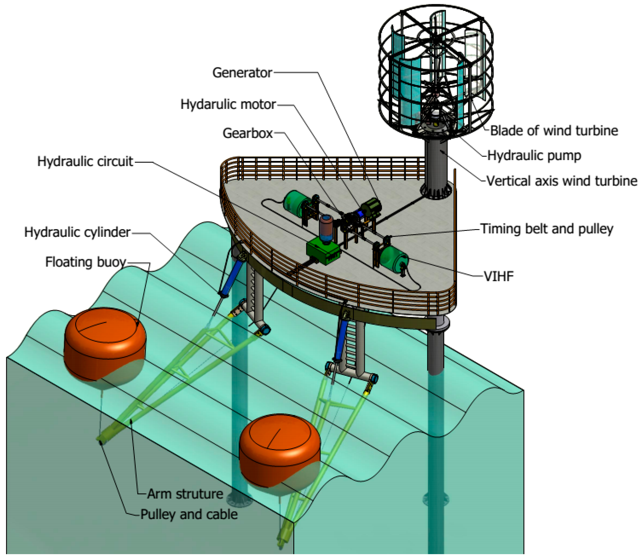
Figure 1. The configurations of the proposed HWWECS.
Jmse 12 01093 g001
Figure 2. Configurations of the WEC unit.
Jmse 12 01093 g002
Figure 3. Force analysis diagram of the floating buoy.
Jmse 12 01093 g003
Figure 4. Specification of the proposed VAWT and flow velocities of VAWT.
Jmse 12 01093 g004
Figure 5. Schematic of the basic hydraulic circuit.
Jmse 12 01093 g005
Figure 6. The d–q axis simplified model.
Jmse 12 01093 g006
Figure 7. The proposed hybrid mechanism specification.
Jmse 12 01093 g007
Figure 8. Hydrodynamic parameters were obtained through Frequency Domain Analysis (FDA) using the WAMIT for the heave and surge modes of motion. Regular waves were considered with a draft (b) of 1.5 m and a buoy radius (a) of 1.5 m in a water depth (h) equal to 10 m.
Jmse 12 01093 g008
Table 1. The working condition’s input parameters.
NotationNameValueUnit
V a Wind speed12m/s
h Water depth10m
H Wave height1.5m
ω w Wave frequency2.2rad/s
φ Phase difference π / 2 rad
Table 2. PTO parameters.
NotationNameValueUnit
a Buoy diameter3.0m
r p Pinion diameter0.1m
k g Gearbox ratio4
I g Generator inertia1kg.m2
b Initial draft1.5m
Table 3. VAWT specification.
NameValue
Rotor diameter (m)6
Number of blades3
Chord length (m)0.25
Height of rotor (m)4
Induced velocity (m/s)7
Table 4. Specification of Hydraulic components.
ComponentsNotationQuantityValueSI Unit
Hydraulic pump D p Displacement2421 cm3/rev
1 / ( 2 π × 10 6 ) m 3 / rad
η v p Volumetric efficiency0.95
η T p Mechanical efficiency0.98
I p Inertia0.046 kg × m 2
Hydraulic motor D m Displacement80.41 cm3/rev
1 / ( 2 π × 10 6 ) m 3 / rad
η v m Volumetric efficiency0.95
η T m Mechanical efficiency0.98
I m Inertia0.021 kg × m 2
Table 5. PMG modeling parameters.
QuantityValue
Number of poles20
Stator resistance0.62 Ω
d-axis and q-axis stator inductance0.0122 H
Magnetic flux0.12 Wb
Disclaimer/Publisher’s Note: The statements, opinions and data contained in all publications are solely those of the individual author(s) and contributor(s) and not of MDPI and/or the editor(s). MDPI and/or the editor(s) disclaim responsibility for any injury to people or property resulting from any ideas, methods, instructions or products referred to in the content.