
Direct Adaptive Multi-Resampling Turbo Equalizer for Underwater Acoustic Single-Carrier Communication


Abstract
:1. Introduction
- (1)
- A two-stage adaptive multi-sampling turbo equalizer is proposed, which realizes robust and reliable underwater acoustic communication by combining an adaptive multi-resampling equalizer and parallel turbo equalizer.
- (2)
- An adaptive resampling method is proposed to adaptively update the resampling rate of the equalizer by detecting the equalization coefficient, to achieve Doppler estimation and compensation.
2. System Model
2.1. Signal Model
2.2. Direct Adaptive Multi-Resampling Turbo Equalizer
2.2.1. Adaptive Multi-Resampling Equalizer
2.2.2. Parallel Turbo Equalizer
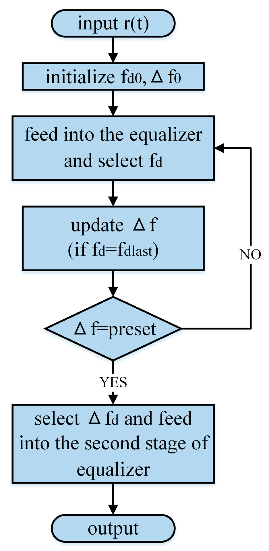
3. Adaptive Resampling Method
3.1. Adaptive Process
3.2. Complexity Analysis
4. Performance Evaluations
4.1. Simulations
4.1.1. Feasibility
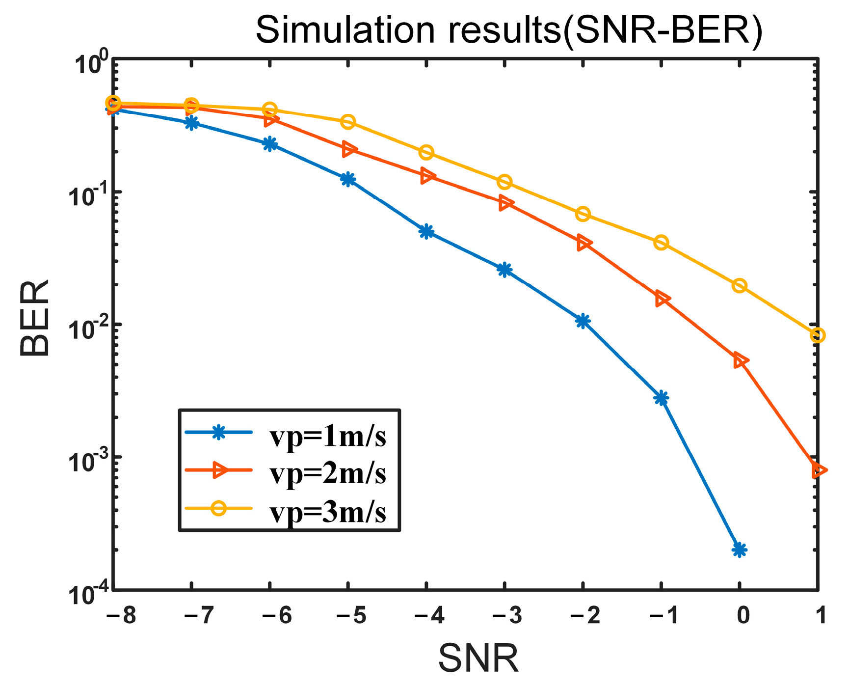
4.1.2. Reliability
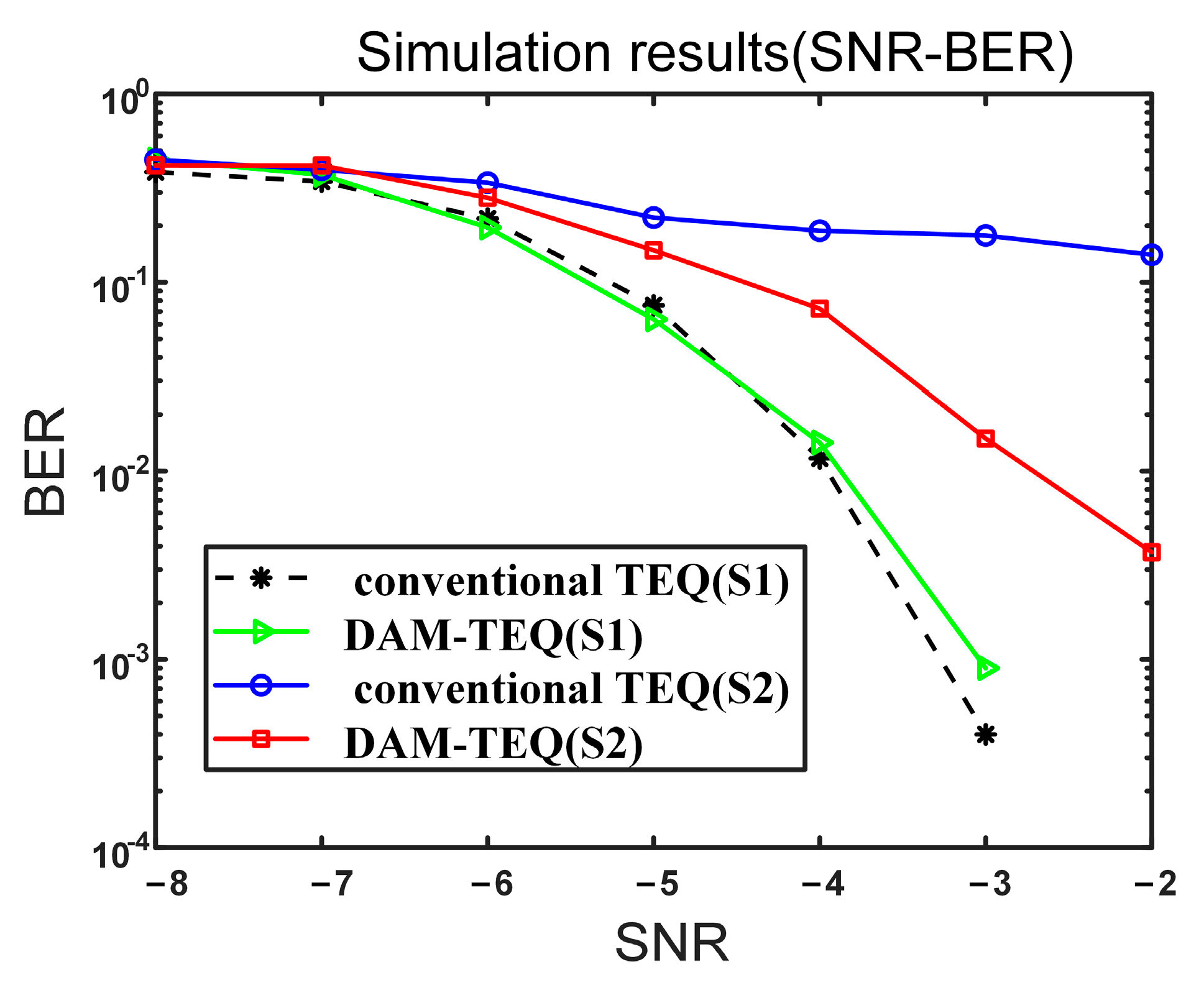
4.1.3. Comparison
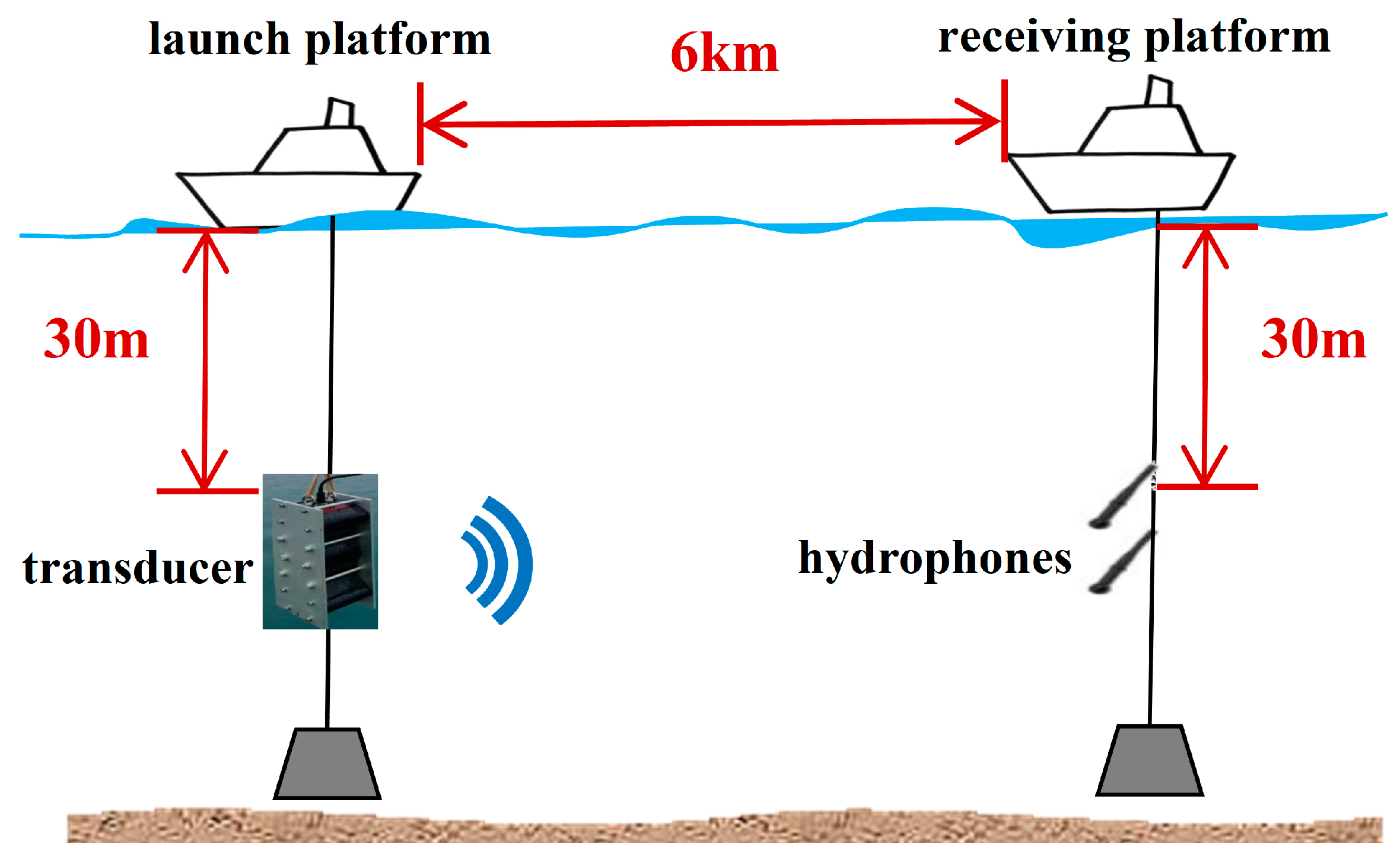
4.2. Lake Experiment
5. Conclusions
Author Contributions
Funding
Institutional Review Board Statement
Informed Consent Statement
Data Availability Statement
Conflicts of Interest
References
- Yang, Y.; Xiao, Y.; Li, T. A survey of autonomous underwater vehicle formation: Performance, formation control, and communication capability. IEEE Commun. Surv. Tutor. 2021, 23, 815–841. [Google Scholar] [CrossRef]
- Qu, F.; Wang, Z.; Yang, L.; Wu, Z. A journey toward modeling and resolving doppler in underwater acoustic communications. IEEE Commun. Mag. 2016, 54, 49–55. [Google Scholar] [CrossRef]
- Chitre, M.; Shahabudeen, S.; Stojanovic, M. Underwater acoustic communications and networking: Recent advances and future challenges. Mar. Technol. Soc. J. 2008, 42, 103–116. [Google Scholar] [CrossRef]
- Stojanovic, M.; Preisig, J. Underwater acoustic communication channels: Propagation models and statistical characterization. IEEE Commun. Mag. 2009, 47, 84–89. [Google Scholar] [CrossRef]
- Singer, A.C.; Nelson, J.K.; Kozat, S.S. Signal processing for underwater acoustic communications. IEEE Commun. Mag. 2009, 47, 90–96. [Google Scholar] [CrossRef]
- Yuan, Z.-K.; Sui, T.-Y.; Li, Y.; Huang, H.-N. The estimation and compensation of Doppler effect on underwater acoustic spread spectrum communication. J. Electron. Inf. Technol. 2012, 34, 51–56. [Google Scholar] [CrossRef]
- Johnson, M.; Freitag, L.; Stojanovic, M. Improved Doppler tracking and correction for underwater acoustic communications. In Proceedings of the 1997 IEEE International Conference on Acoustics, Speech, and Signal Processing, Munich, Germany, 21–24 April 1997; pp. 575–578. [Google Scholar] [CrossRef]
- Sharif, B.S.; Neasham, J.; Hinton, O.R.; Adams, A.E. A computationally efficient Doppler compensation system for underwater acoustic communications. IEEE J. Ocean. Eng. 2000, 25, 52–61. [Google Scholar] [CrossRef]
- Li, B.; Zhou, S.; Stojanovic, M.; Freitag, L.; Willett, P. Multicarrier communication over underwater acoustic channels with nonuniform Doppler shifts. IEEE J. Ocean. Eng. 2008, 33, 198–209. [Google Scholar] [CrossRef]
- Huang, J.; Guo, S.; Guo, Z.; Chen, G. Doppler compensation for underwater acoustic broadband signal. Tech. Acoust. 2009, 28, 99–103. [Google Scholar]
- Jiang, X.; Zeng, W.-J.; Li, X.-L. Time delay and Doppler estimation for wideband acoustic signals in multipath environments. J. Acoust. Soc. Am. 2011, 130, 850–857. [Google Scholar] [CrossRef]
- Li, W.; Preisig, J.C. Estimation of rapidly time-varying sparse channels. IEEE J. Ocean. Eng. 2007, 32, 927–939. [Google Scholar] [CrossRef]
- Byun, S.-H.; Seong, W.; Kim, S.-M. Sparse underwater acoustic channel parameter estimation using a wideband receiver array. IEEE J. Ocean. Eng. 2013, 38, 718–729. [Google Scholar] [CrossRef]
- Qu, F.; Nie, X.; Xu, W. A two-stage approach for the estimation of doubly spread acoustic channels. IEEE J. Ocean. Eng. 2014, 40, 131–143. [Google Scholar] [CrossRef]
- Jiang, W.; Tong, F.; Zhu, Z. Exploiting rapidly time-varying sparsity for underwater acoustic communication. IEEE Trans. Veh. Technol. 2022, 71, 9721–9734. [Google Scholar] [CrossRef]
- Gomes, J.; Barroso, V. Doppler compensation in underwater channels using time-reversal arrays. In Proceedings of the 2003 IEEE International Conference on Acoustics, Speech, and Signal Processing, 2003, Proceedings (ICASSP’03), Hong Kong, China, 6–10 April 2003; p. V-81. [Google Scholar] [CrossRef]
- Stojanovic, M.; Catipovic, J.A.; Proakis, J.G. Phase-coherent digital communications for underwater acoustic channels. IEEE J. Ocean. Eng. 1994, 19, 100–111. [Google Scholar] [CrossRef]
- Douillard, C.; Jézéquel, M.; Berrou, C.; Electronique, D.; Picart, A.; Didier, P.; Glavieux, A. Iterative correction of intersymbol interference: Turbo-equalization. Eur. Trans. Telecommun. 1995, 6, 507–511. [Google Scholar] [CrossRef]
- Tuchler, M.; Singer, A.C.; Koetter, R. Minimum mean squared error equalization using a priori information. IEEE Trans. Signal Process. 2002, 50, 673–683. [Google Scholar] [CrossRef]
- Tuchler, M.; Koetter, R.; Singer, A.C. Turbo equalization: Principles and new results. IEEE Trans. Commun. 2002, 50, 754–767. [Google Scholar] [CrossRef]
- Roy, S.; Duman, T.M.; McDonald, V.; Proakis, J.G. High-rate communication for underwater acoustic channels using multiple transmitters and space–time coding: Receiver structures and experimental results. IEEE J. Ocean. Eng. 2007, 32, 663–688. [Google Scholar] [CrossRef]
- Choi, J.W.; Riedl, T.J.; Kim, K.; Singer, A.C.; Preisig, J.C. Adaptive linear turbo equalization over doubly selective channels. IEEE J. Ocean. Eng. 2011, 36, 473–489. [Google Scholar] [CrossRef]
- Blackmon, F.; Sozer, E.; Proakis, J. Iterative equalization, decoding, and soft diversity combining for underwater acoustic channels. In Proceedings of the OCEANS’02 MTS/IEEE, Biloxi, MI, USA, 29–31 October 2002; pp. 2425–2428. [Google Scholar] [CrossRef]
- Otnes, R.; Eggen, T.H. Underwater acoustic communications: Long-term test of turbo equalization in shallow water. IEEE J. Ocean. Eng. 2008, 33, 321–334. [Google Scholar] [CrossRef]
- Tüchler, M.; Singer, A.C. Turbo equalization: An overview. IEEE Trans. Inf. Theory 2011, 57, 920–952. [Google Scholar] [CrossRef]
- Yellepeddi, A.; Preisig, J.C. Adaptive equalization in a turbo loop. IEEE Trans. Wirel. Commun. 2015, 14, 5111–5122. [Google Scholar] [CrossRef]
- Zheng, Y.R.; Wu, J.; Xiao, C. Turbo equalization for single-carrier underwater acoustic communications. IEEE Commun. Mag. 2015, 53, 79–87. [Google Scholar] [CrossRef]
- Yang, Z.; Zheng, Y.R. Iterative channel estimation and turbo equalization for multiple-input multiple-output underwater acoustic communications. IEEE J. Ocean. Eng. 2015, 41, 232–242. [Google Scholar] [CrossRef]
- Xi, J.; Yan, S.; Xu, L. Direct-adaptation based bidirectional turbo equalization for underwater acoustic communications: Algorithm and undersea experimental results. J. Acoust. Soc. Am. 2018, 143, 2715–2728. [Google Scholar] [CrossRef] [PubMed]
- Duan, W.; Tao, J.; Zheng, Y.R. Efficient adaptive turbo equalization for multiple-input–multiple-output underwater acoustic communications. IEEE J. Ocean. Eng. 2017, 43, 792–804. [Google Scholar] [CrossRef]
- Xi, J.; Yan, S.; Xu, L.; Zhang, Z.; Zeng, D. Frequency–time domain turbo equalization for underwater acoustic communications. IEEE J. Ocean. Eng. 2019, 45, 665–679. [Google Scholar] [CrossRef]
- Tu, K.; Duman, T.M.; Stojanovic, M.; Proakis, J.G. Multiple-resampling receiver design for OFDM over Doppler-distorted underwater acoustic channels. IEEE J. Ocean. Eng. 2012, 38, 333–346. [Google Scholar] [CrossRef]
- Stojanovic, M.; Catipovic, J.; Proakis, J.G. Adaptive multichannel combining and equalization for underwater acoustic communications. J. Acoust. Soc. Am. 1993, 94, 1621–1631. [Google Scholar] [CrossRef]
- Lou, H.; Xiao, C. Soft-decision feedback turbo equalization for multilevel modulations. IEEE Trans. Signal Process. 2010, 59, 186–195. [Google Scholar] [CrossRef]
- Peng, C.; Wang, L.; Ji, H.; Zhang, S.; Yang, C. Multi-Resampling Equalizer for Underwater Acoustic Single Carrier Communication. In Proceedings of the 2023 IEEE International Conference on Signal Processing, Communications and Computing (ICSPCC), Zhengzhou, China, 14–17 November 2023; pp. 1–4. [Google Scholar] [CrossRef]
- Koetter, R.; Singer, A.C.; Tuchler, M. Turbo equalization. IEEE Signal Process. Mag. 2004, 21, 67–80. [Google Scholar] [CrossRef]


| Structure | Increased Multiplications | Increased Additions |
|---|---|---|
| DAM-TEQ(I) | ||
| DAM-TEQ(II) |
| Parameter | Value |
|---|---|
| Carrier frequency | 450 Hz |
| Modulation mode | BPSK |
| Sequence length | 1296 bits |
| Baud rate | 200 Baud |
| Bandwidth | 200 Hz |
| Initial sampling rate | 40,000 Hz |
| Convolutional coding | (2, 1, 3) |
| Group | Recorded Data | BER of the Conventional TEQ | BER of the DAM-TEQ | Update Times | Iteration Times |
|---|---|---|---|---|---|
| 1 | 11:54:45 | 0 | 0 | 4 | 1 |
| 2 | 11:54:45(−5 dB) | 0 | 0 | 4 | 3 |
| 3 | 11:56:25 | 0.4861 | 0 | 4 | 4 |
| 4 | 11:56:25(−5 dB) | 0.4961 | 0.1690 | 4 | - |
| 5 | 11:58:05 | 0.4846 | 0 | 4 | 2 |
| 6 | 11:58:05(−5 dB) | 0.4468 | 0 | 4 | 4 |
| 7 | 11:53:05 | 0.4653 | 0.1705 | 4 | - |
Disclaimer/Publisher’s Note: The statements, opinions and data contained in all publications are solely those of the individual author(s) and contributor(s) and not of MDPI and/or the editor(s). MDPI and/or the editor(s) disclaim responsibility for any injury to people or property resulting from any ideas, methods, instructions or products referred to in the content. |
© 2024 by the authors. Licensee MDPI, Basel, Switzerland. This article is an open access article distributed under the terms and conditions of the Creative Commons Attribution (CC BY) license (https://creativecommons.org/licenses/by/4.0/).
Share and Cite
Lin, Z.; Wang, L.; Peng, C.; Zhang, S. Direct Adaptive Multi-Resampling Turbo Equalizer for Underwater Acoustic Single-Carrier Communication. J. Mar. Sci. Eng. 2024, 12, 1271. https://doi.org/10.3390/jmse12081271
Lin Z, Wang L, Peng C, Zhang S. Direct Adaptive Multi-Resampling Turbo Equalizer for Underwater Acoustic Single-Carrier Communication. Journal of Marine Science and Engineering. 2024; 12(8):1271. https://doi.org/10.3390/jmse12081271
Chicago/Turabian StyleLin, Zehua, Lei Wang, Cong Peng, and Shuhao Zhang. 2024. "Direct Adaptive Multi-Resampling Turbo Equalizer for Underwater Acoustic Single-Carrier Communication" Journal of Marine Science and Engineering 12, no. 8: 1271. https://doi.org/10.3390/jmse12081271