Abstract
Flexible pipe is one of the most important types of equipment applied in the deep-water development of oil and gas and deep-sea metal mining. The carcass of an unbonded flexible pipe with a typical interlocked structure prevents buckling failure under external hydrostatic pressure. The process and principle of carcass layer deformation are described, and a three-dimensional finite element model with solid-shell elements is developed to simulate the cold forming process of a metal strap subjected to a series of rollers. The deflection and deformation behavior in the bend-rolling and interlocking process are investigated, and the residual stress due to deformation is calculated. Taking the carcass layer of a 4-inch internal diameter flexible pipe as an example, a three-dimensional finite element model of the carcass layer loaded with external hydrostatic pressure is developed. The buckling collapse of the carcass layer is evaluated considering different initial imperfections, including residual stress. The results show that the critical pressure can be 60% less than under ideal conditions when the geometric imperfection, material nonlinearity and residual stress due to deformation are considered, which indicates that the effect of residual stress on buckling collapse cannot be ignored. The numerical model and results provide an efficient method and basis for nonlinear buckling analysis and a collapse-resistant unbonded flexible pipe design for industry.
1. Introduction
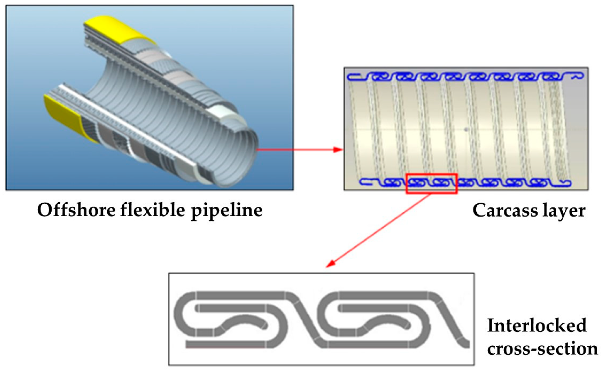
Offshore flexible pipelines are crucial transport equipment for the development of deep-water oil and gas resources and deep-sea mining [1]. They are composed of polymer layers and various metal spiral reinforcement layers in an unbonded composite, providing high axial tensile stiffness and radial compressive stiffness while maintaining low bending stiffness [2,3]. As marine resource exploitation progressively moves to deeper water, the metal carcass layer is used in the innermost part of the pipeline to resist the external hydrostatic pressure, preventing buckling collapse failure [4]. To design a pipeline that does not collapse, it is necessary to accurately predict the nonlinear buckling behavior of the carcass layer. The carcass layer is formed by repeatedly cold bending and pressing stainless steel strips into an interlocking structure (as shown in Figure 1). The complexity of the geometric shape and consideration of various imperfections including material properties add to the challenges in analyzing the nonlinear buckling of the carcass layer.
To reduce the computational burden associated with complex geometries, many researchers have made the carcass layer equivalent to one homogeneous cylinder with a certain thickness [5,6,7,8,9] and then employed Timoshenko’s classical analytical formula for the first-order elastic instability of a cylinder under uniform external pressure [10] to calculate the critical pressure of the carcass layer. It should be noted that this critical pressure represents the ultimate external pressure that the carcass layer can withstand before buckling and collapse and has important application value for pipeline design. However, this approach fails to directly account for the complex cross-sectional shapes and material nonlinearity of the carcass layer, thus only providing the critical pressure under ideal conditions. Moreover, the critical pressure obtained using the equivalent method is usually conservative, which to some extent limits its engineering applications. To address this limitation, researchers have introduced finite element methods into the analysis of the buckling and collapse of the carcass layer. Alfredo et al. [8] used ANSYS 16.0 software to establish three-dimensional finite element models of the carcass layer, employing solid elements and considering inter-layered contact and friction. Two numerical models were developed, one matching the true carcass layer structure and the other ignoring the helical winding angle. Their analysis found that the buckling behavior from both models was nearly identical, suggesting that the impact of the helical winding angle can be neglected for the buckling behavior of the carcass layer. Victor et al. [10] proposed a simplified numerical model using beam elements with the actual cross-section of the carcass layer for buckling analysis. Although the computational cost is reduced, inherent limitations such as the assumption of plane sections and neglect of the Poisson effect led to overestimated results, affecting the accuracy. Tang et al. [11] proposed a three-dimensional finite element model of the carcass layer that simultaneously ensured computational accuracy and efficiency and quantitatively assessed the impact of initial imperfections such as geometric ovality and material nonlinearity on buckling behavior. Chen Yanfei et al. [12] used a three-dimensional finite element model to analyze the critical pressure under axial tensile loads. The results showed that the critical pressure significantly decreased as the carcass layer was gradually tensioned, while larger tensile forces had a very low impact on the critical pressure. Subsequent investigations focus on the buckling and collapse behavior of the carcass layer with the overall curvature of the flexible pipeline or the external pressure armor layers [13]. Although these finite element models represent significant advancements over analytical methods, none considered the impact of residual stresses from the processing of the carcass layer, causing the predicted results to be biased toward danger.

Figure 1.
A schematic diagram of an unbonded flexible pipe and the carcass layer [6].
Figure 1.
A schematic diagram of an unbonded flexible pipe and the carcass layer [6].
Residual stress is the internal stress that remains in equilibrium within an object after the elimination of external forces due to uneven plastic deformation. The forming of the carcass layer involves subjecting a steel strip with a certain thickness to various large deformations at a specific rate (as shown in Figure 2), inevitably resulting in a final formed section containing significant amounts of residual stresses, which further affects the buckling resistance of the carcass layer. Considering complex conditions such as material nonlinearity, inter-layered contact and friction and large deformations, Liu et al. [14] used a three-dimensional finite element model to conduct a process analysis of the multiple cold bending forming processes of the carcass layer. The distribution of residual stresses was obtained, but the impact of the interlocking process and the residual stresses on the buckling behavior was not provided. It should be pointed out that it is necessary to carry out direct checking of pipelines using appropriate and economical methods [15,16]; however, there is currently little literature on the detection of residual stress in the formed carcass layer of flexible pipelines. Based on the forming principles of the carcass layer, this study establishes three-dimensional finite element models for typical cold bending processes, such as roller bending and interlocking. The deformation and stress response of metal materials during the forming process are simulated, and the nonlinear buckling behavior of the carcass layer containing processing residual stresses is then analyzed. Additionally, the impact of different initial imperfections on the critical pressure of the carcass layer is discussed.
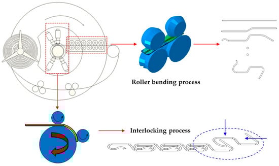
Figure 2.
A schematic diagram of the cold bending forming process of the carcass layer.
2. Deformation Principles of the Carcass Layer
Manufacturing of the carcass layer is accomplished through an entire production line, which includes the core carcass layer interlocking machine and several pieces of auxiliary equipment, such as traction devices, wire racks, winding racks and spools. However, the core technology for the formation of the carcass layer is concentrated in the interlocking machine. A schematic diagram of the front panel of the carcass layer interlocking machine is shown in Figure 2. It can be observed that the cold bending forming process of the carcass layer can be broadly divided into two steps:
- The first step is roller bending, in which the flat stainless steel strip undergoes transverse squeeze and bending with a series of rollers of different shapes, eventually forming an “S”-shaped cross-section. The steel strip moves through friction between the rollers and the strip, which is generated by the transverse squeeze of the rollers on the strip. Additionally, the rollers with different outer diameters ensure a certain tension between the rollers during the movement of the strip.
- The second step involves interlocking, when the S-shaped cross-section is transformed into an interlocking profile through four sets of radial pressure rollers. Simultaneously, the steel strip is spirally wound under a certain tension through the rotation of the centering wheel of the interlocking machine and the pressure and friction exerted by the rollers.
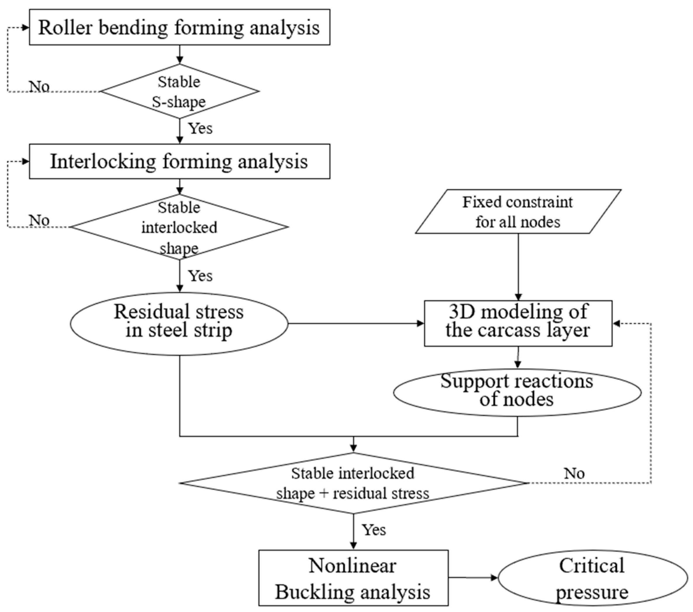
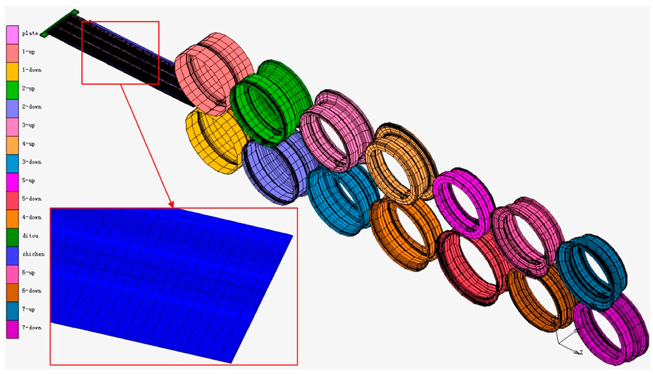
Based on the above-mentioned processing and forming principles, the carcass layer structure of an unbonded flexible pipeline with a typical cross-section is formed. To provide a specific description of the finite element model, this study uses the carcass layer of the offshore flexible pipeline with a four-inch internal diameter from an actual application as a reference case. Detailed dimensions and material properties are provided in the literature [17], where the material quickly enters a significant hardening phase after a short linear elastic stage. To accurately obtain the cross-section profile, actual process parameters are used to simulate the cold bending formation process. During the roller bending stage, the stainless steel strip with a thickness of 1 mm passes sequentially through seven sets of rollers with different shapes, with the schematic diagram of the roller patterns shown in Figure 3. The diameter of the first set of rollers is 16 mm, with each subsequent roller increasing in diameter by 0.5 mm. In the interlocking stage, four sets of radial pressure rollers are used for the interlocking analysis, the diameter of each roller conforming to the final design profile of the carcass layer. The process of carcass layer forming and the nonlinear buckling analysis simulation based on the finite element analysis method is shown in Figure 4. The specific methods and conclusions are described in Section 3, Section 4 and Section 5.
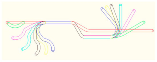
Figure 3.
Seven sets of roller patterns in roller bending stage.
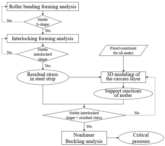
Figure 4.
Flowchart of nonlinear buckling of carcass layer considering residual stress due to deformation based on finite element method.
3. Numerical Simulation of Carcass Layer Deformation Process
Due to the large deformation, material nonlinearity and contact nonlinearity present in the roller bending and interlocking cold forming processes of the carcass layer, deviations or even non-convergence of the computational results often occur, introducing challenges into simulating the manufacturing process. Therefore, in this study, the finite element analysis software MSC.Marc is utilized to simulate the two main forming processes of the carcass layer and predict the mechanical response during the cold bending forming process of the strip.
3.1. Finite Element Analysis for Roller Bending Forming of Steel Strip
3.1.1. Elements and Mesh
Considering that the stiffness of the rollers is typically much greater than the bending stiffness of the steel strip, analytical rigid surface elements are used to simulate the outer surface of the rollers. To accurately predict the mechanical response of the steel strip during the cold bending forming process and ensure computational efficiency, the model uses two-dimensional shell elements (SHELL185) for analysis, with eleven integration points along the thickness direction of the steel strip. Based on the stress–strain curve of stainless steel material, an isotropic hardening rule is employed to describe the material’s plastic behavior [18]. The specific constitutive relationship is expressed with curve fitting in the following form:
where represents the elastic strain caused by volumetric deformation, denotes the plastic strain induced by shape changes and and are the material fitting coefficients.
Mesh partitioning is a crucial technique in finite element methods to accurately analyze and predict the deformation and stress during the cold forming process of carcass layers. An excessively coarse mesh directly impacts the accuracy of computational results, while an overly fine mesh significantly decreases computational efficiency. Therefore, the model employs mesh refinement in regions where cold bending deformation occurs based on the shape of the carcass layer, while areas where no cold bending deformation occurs have larger mesh sizes. The distribution of elements along the axial direction of the strip remains consistent, resulting in a total of 6208 elements in the strip model. Detailed mesh partitioning of the strip and finite element model for roller bending can be found in Figure 5.

Figure 5.
The finite element model for the cold bending deformation of the strip.
To simulate the contact behavior between the strip and the rollers during the forming process of the carcass layer, surface-to-surface contact elements are employed, with the roller surface designated as the master surface and the strip surface as the slave surface. The penalty method is utilized to simulate the normal contact behavior, with the penalty stiffness coefficient set to 0.1. For the tangential contact behavior, Coulomb’s law of friction is employed, where the static friction coefficient is set to 0.2 and the dynamic friction coefficient is set to 0.1.
3.1.2. Constraints and Loading
The roller bending forming of the carcass layer is a dynamic process. In the initial loading stage, the front end of the steel strip is squeezed by the first set of rollers, and then, a rotational speed of 2.13 rad/s is applied to the drive rollers. This causes the steel strip to move forward due to friction with the rollers until it enters the next set of rollers. It is important to note that the rotational speeds of the seven sets of rollers are different to ensure that a certain axial tension is maintained between the rollers. Additionally, all nodes on the tail end face of the steel strip are constrained in terms of degrees of freedom to only allow for axial displacement, ensuring that the steel strip does not experience lateral slippage during the roller bending process.
3.1.3. Analysis Results
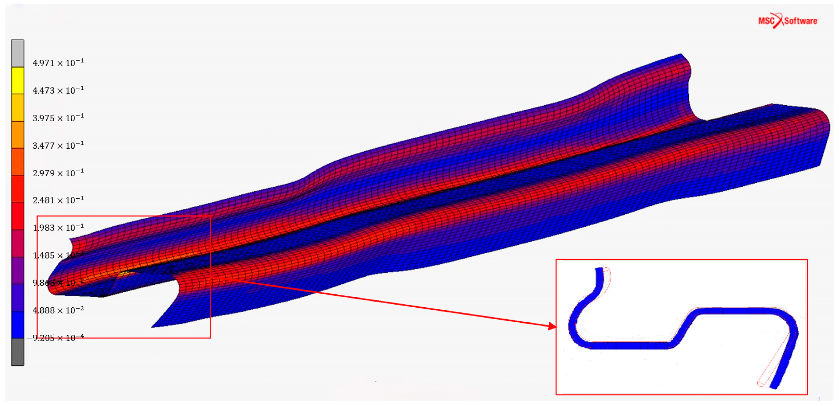
The distribution of equivalent plastic strain in the steel strip during the roller bending process is shown in Figure 6. It can be seen that significant plastic deformation occurs at the bends of the steel strip, while the straight sections exhibit almost no plastic strain. As the rollers drive the steel strip, the extent of plastic deformation gradually increases, and the transition is smooth, with no irregular forming responses of the local buckling or waves observed in the simulation process. After passing through the last set of rollers, the equivalent plastic strain in the steel strip reaches 35%. Due to spring-back deformation, the final formed profile of the steel strip shows a slight difference at the transverse ends compared to the shape of the last set of rollers. It can also be observed that a reduction in thickness occurs at the bend regions of the steel strip, which is due to the material’s Poisson effect.
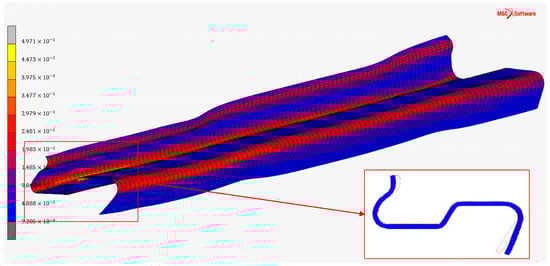
Figure 6.
The equivalent plastic strain contour of the steel strip in the roller bending stage.
The equivalent stress distribution along the width of the steel strip during the roller bending process was obtained by using the post-processing module, as illustrated in Figure 7. It can be clearly observed that there are stress peaks at the five bend corners, with the most prominent stress extremes at the inner bend corners (positions 3 and 4). Consequently, significant residual stress emerges at the bend corners once the load is removed. Thus, in the roller bending stage of the carcass layer, residual stresses at the inner bend corners are extracted.
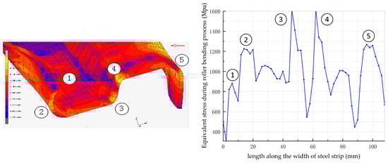
Figure 7.
The distribution of the equivalent stress along the width of the steel strip (the circled number represents the bend corner number).
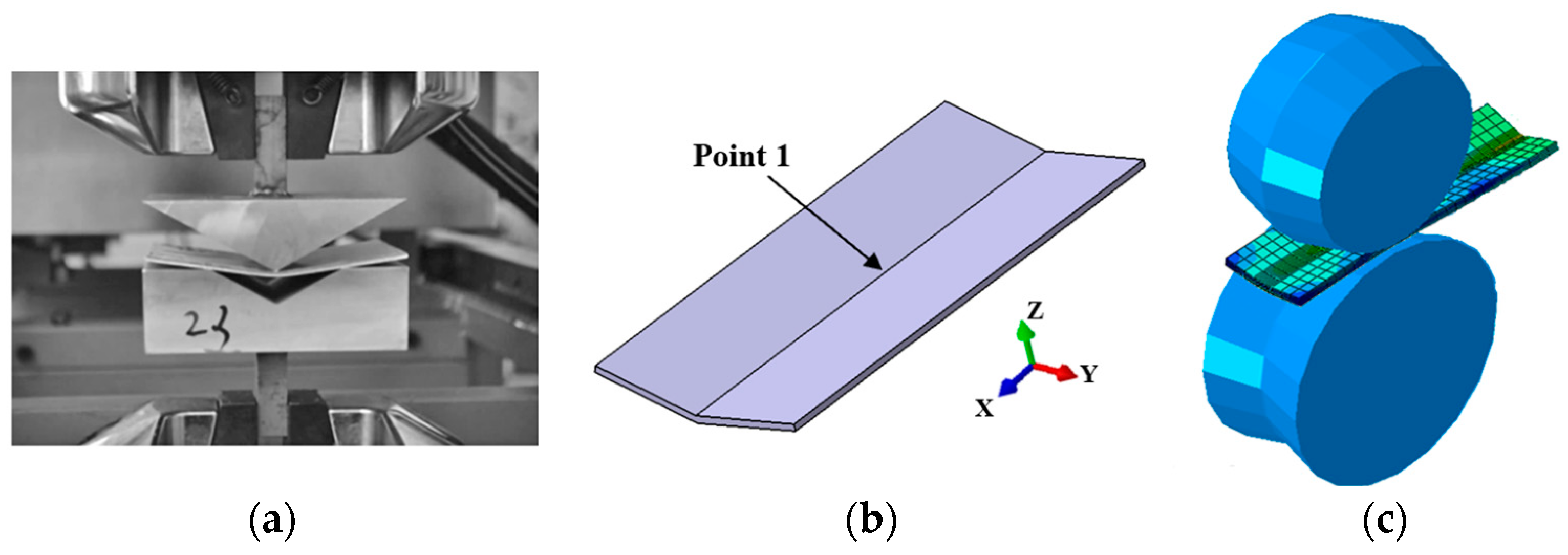
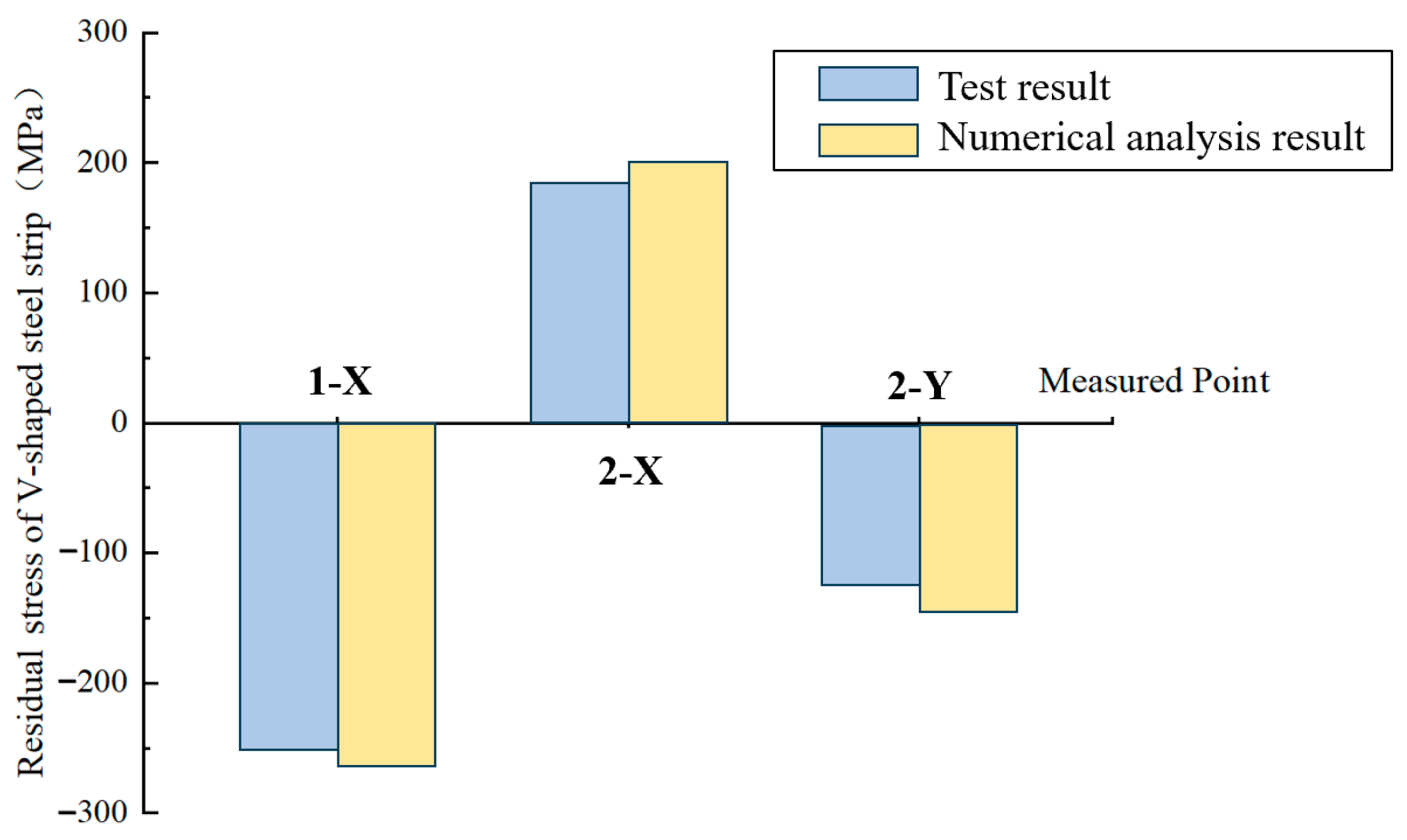
In order to validate the cold bending finite element model, a comparative analysis is conducted between the results of the cold bending test conducted on steel strips in reference [14] and the results from the numerical model proposed in this study. This experiment is conducted on a steel strip with a thickness of 2.3 mm, which was subjected to cold bending hardening with a V-shaped rigid contact surface (Figure 8a). The residual stress values at the marked points shown in Figure 8b were measured (point 1 represents the point in the inner bending surface, point 2 represents the point in the corresponding outer bending surface and X and Y indicate the stress direction). Using the numerical methods introduced in this section, one set of roller models with V-shaped contact surfaces is established (Figure 8c), and an analysis of the deformation of the steel strip model due to driving the roller wheels is conducted. The calculated values of the residual stresses on the inner and outer surfaces at the marked points are compared with the measured results, as shown in Figure 9, and the two are in good agreement, thus verifying the correctness of the proposed finite element model.
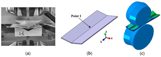
Figure 8.
Cold bending test of steel strip and corresponding finite element model: (a) testing device; (b) marked point; and (c) model of one set of rollers.

Figure 9.
Comparison of residual stress analysis results at marked points.
3.2. Finite Element Analysis for Interlocking Forming Process
3.2.1. Model Description
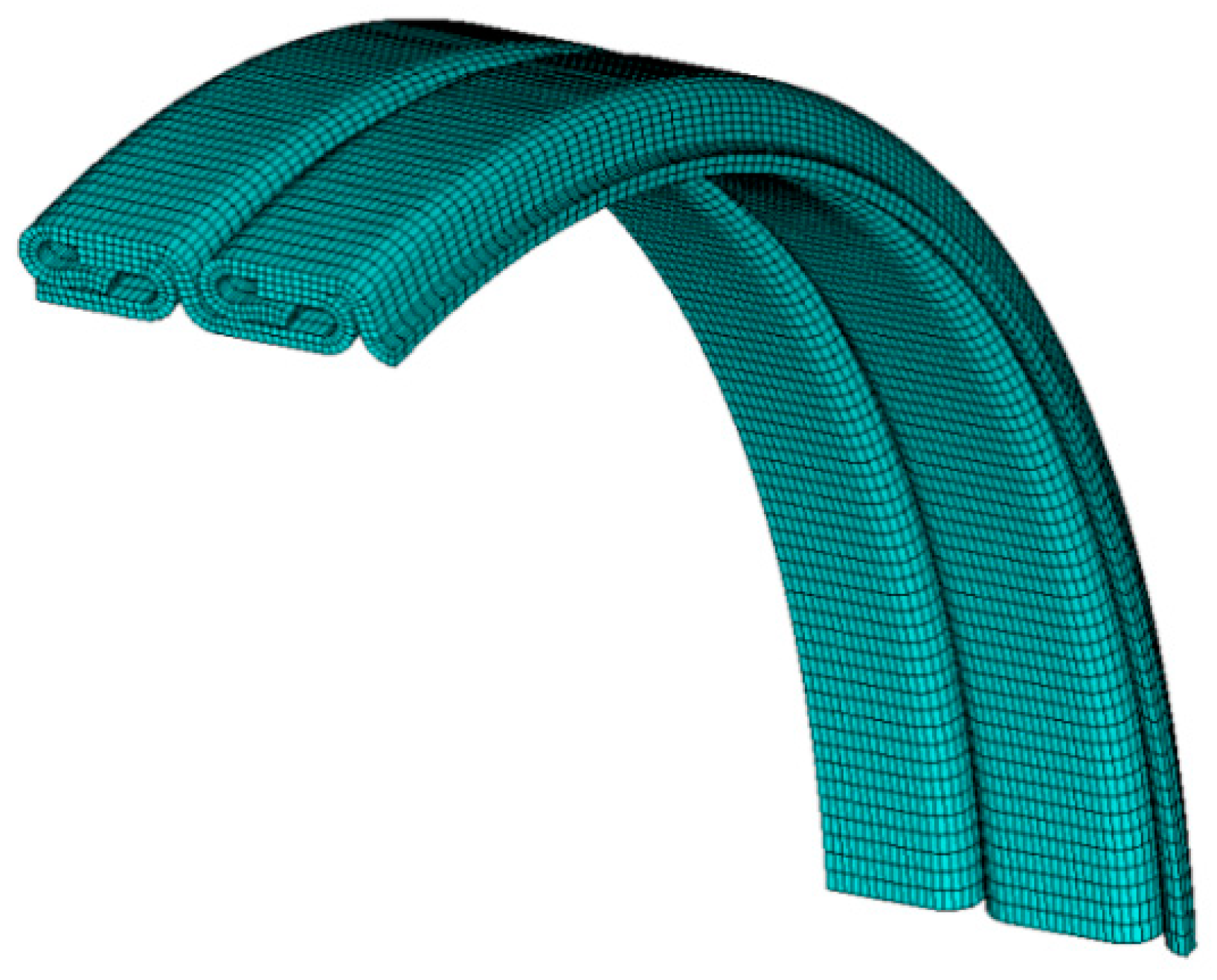
In the simulation of the interlocking forming process, the material character, mesh and contact settings of the pressure rollers and steel strip are the same as those in the roller bending stage. The difference is mainly reflected in the loading conditions. In the initial loading phase, the front end of the S-shaped steel strip (formed in the roller bending stage) is squeezed by the set of guide rollers, and the relative friction generated by the rotation of the centering wheel provides the driving force for the S-shaped steel strip. As the front end of the steel strip enters the first set of pressure rollers, it is radially squeezed to achieve an interlocking shape. Simultaneously, the rotational speed of the centering wheel is set to 1.65 rad/s, allowing the steel strip to generate friction with the centering wheel and pressure rollers under radial squeeze, thereby realizing the spiral winding driven by the centering wheel. It is important to note that to ensure the carcass layer has a certain helical angle, the radial pressure rollers are not positioned in one vertical plane and are all drive rollers, further facilitating the spiral winding drive toward the steel strip.
To enhance computational accuracy, an implicit solving law is used in the model, and the Newton–Raphson method is employed to handle various nonlinearities that occur during the forming simulation process. Furthermore, to avoid convergence issues, a positive definite solution and updated Lagrangian method is used for simulation. Displacement and stress–strain responses are extracted for each loading increment step.
3.2.2. Analysis Results
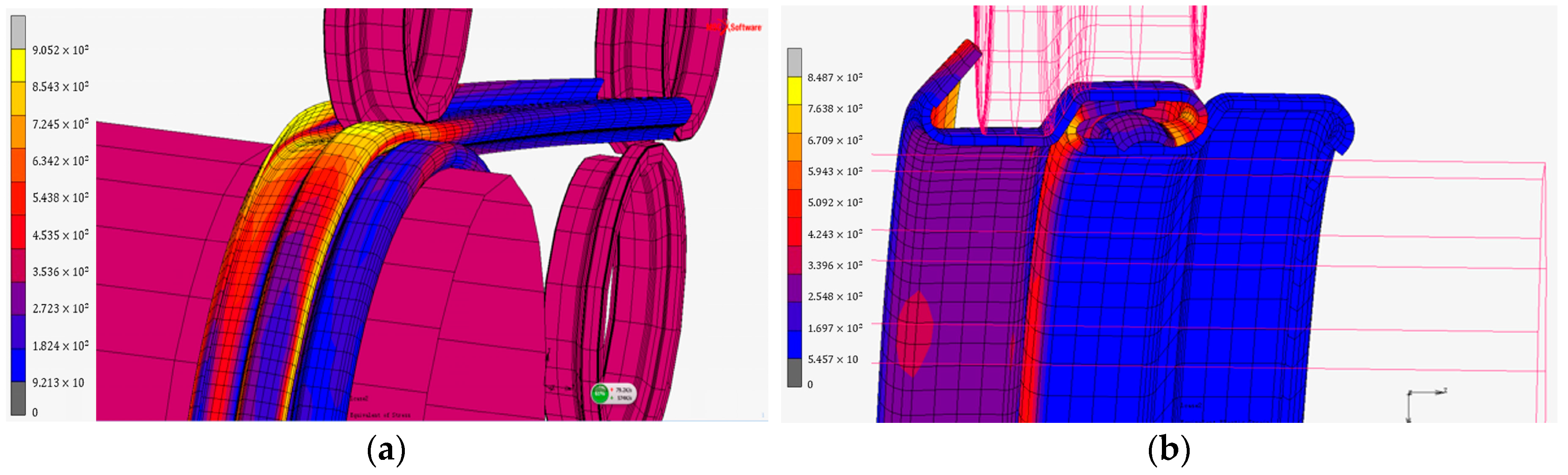
Figure 10 displays the equivalent stress distribution of the “S”-shaped steel strip passing through the first and last sets of radial pressure rollers. It can be seen that significant stress exists throughout the spiral steel strip during the driving process induced by the pressure rollers, with the most notable stress occurring near the pressure rollers. After the squeeze is removed (coming to the second pitch), significant residual stresses are only present at the two outer bend corners of the steel strip (positions 2 and 5 in Figure 7). Thus, in the interlocking stage of the carcass layer, the residual stresses at the outer bend corners are extracted. Additionally, it can be observed in Figure 10b that the final formed cross-section of the carcass layer agrees well with the designed shape, which confirms the correctness of the finite element model.
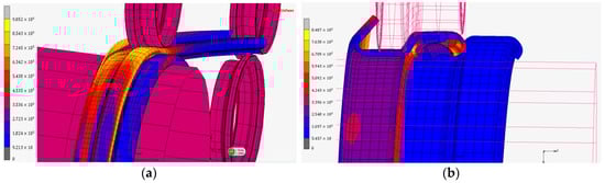
Figure 10.
The equivalent stress contour of the steel strip in the interlocking stage: (a) at the first set of radial pressure rollers; (b) at the last set of radial pressure rollers.
4. Nonlinear Buckling Analysis of the Carcass Layer
4.1. Three-Dimensional Finite Element Model of the Carcass Layer
By ignoring the influence of the helical angle and the eccentricity caused by changes in the thickness of the carcass layer, and considering structural symmetry, a quarter-ring model is established using the finite element analysis software ANSYS. Eight-node three-dimensional solid elements with fully integrated methods are employed, and the model is mapped and meshed as shown in Figure 11. Surface-to-surface contact elements are set up in regions where contact may occur within the carcass layer. Additionally, considering the structural periodic arrangement along the pipeline axis, periodic boundary conditions are applied to ensure the deformation compatibility of the model. Then, uniform pressure loads are applied on the radial outer surface of the carcass layer model. The detailed model parameters can be found in reference [8]. Through the first-order eigenvalue buckling analysis, the critical pressure of the carcass layer is determined to be 47.6 MPa, serving as a reference value under ideal conditions [17]. In order to investigate nonlinear buckling behavior while considering various imperfections, the arc length method is selected for iterative computation until convergence is achieved [19].

Figure 11.
Three-dimensional finite element model of carcass layer [6].
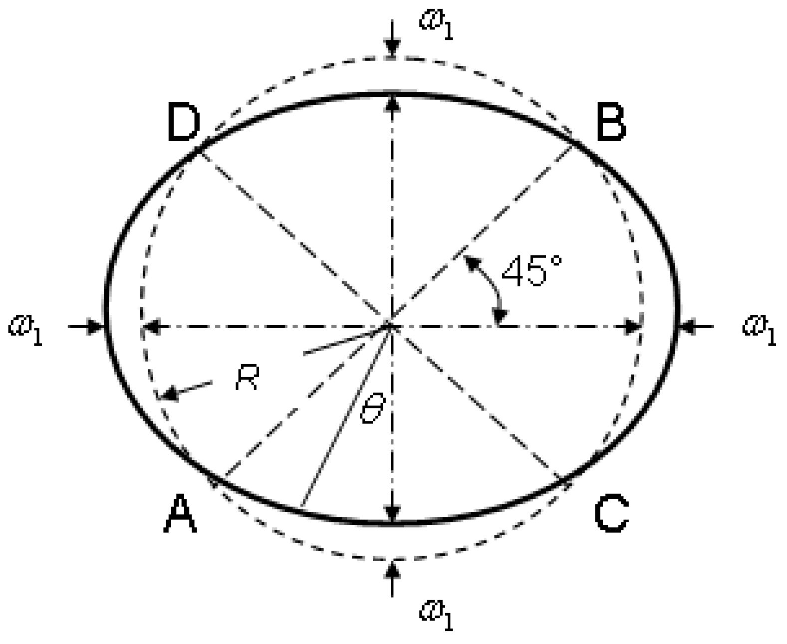
It should be pointed out that ovality is defined as the ratio of the maximum radial deviation of the carcass layer to its curvature radius R, as shown in Figure 12. Considering the engineering requirement that strictly limited the initial ovality of the carcass layer to within 3%, this study selects an ovality of 1% as the representative value of the initial geometric defects.

Figure 12.
Schematic diagram of ovality of carcass layer.
4.2. Nonlinear Buckling of the Carcass Layer Considering Residual Stresses Due to Deformation
Firstly, MATLAB is applied to automatically write files for residual stresses in all six degrees of freedom of the nodes at the bend corners from the ANSYS model. It is necessary to note that when the residual stresses are directly applied, the model will undergo spring-back deformation. Therefore, to ensure that the shape of the carcass layer remains unchanged before the buckling analysis begins, all nodes need to be fixed first, and residual stresses are then applied. Subsequently, the support reaction of each node is extracted using post-processing programs. Next, the displacement constraints are removed, and both the residual stresses and support reactions of the nodes are applied to the model, ensuring that residual stresses are introduced without spring-back deformation. Figure 13 illustrates the equivalent stress contour after applying residual stresses. It can be observed that the residual stress distribution ranges from 300 MPa to 600 MPa, with the maximum residual stress value being approximately seventy-five percent of the material yield strength. This further emphasizes the importance of considering the deformation process when evaluating the buckling resistance of the carcass layer.
Figure 13.
The equivalent stress contour of the initial model after applying residual stresses.
In the literature [17], a three-dimensional finite element model was used to analyze the elastic instability under ideal conditions for this carcass layer with a 4-inch internal diameter, and the first-order eigenvalue was obtained as 47.6 MPa, which was compared with the result calculated by the analytical method. This analytical model used the bending stiffness equivalent method to transform the carcass layer into the circular ring with a certain thickness and diameter, and the critical pressure of the carcass layer was calculated as 47.6 MPa based on Timoshenko’s elastic instability theory. Both results were in good agreement, which confirmed the correctness of the proposed finite element method. Then, the nonlinear buckling behavior of the carcass layer considering the initial geometric ovality and material elasticity–plasticity was further investigated. Therefore, the focus of this study is to introduce the residual stresses that resulted from the cold bending deformation process into the finite element model of the carcass layer and carry out further nonlinear buckling.
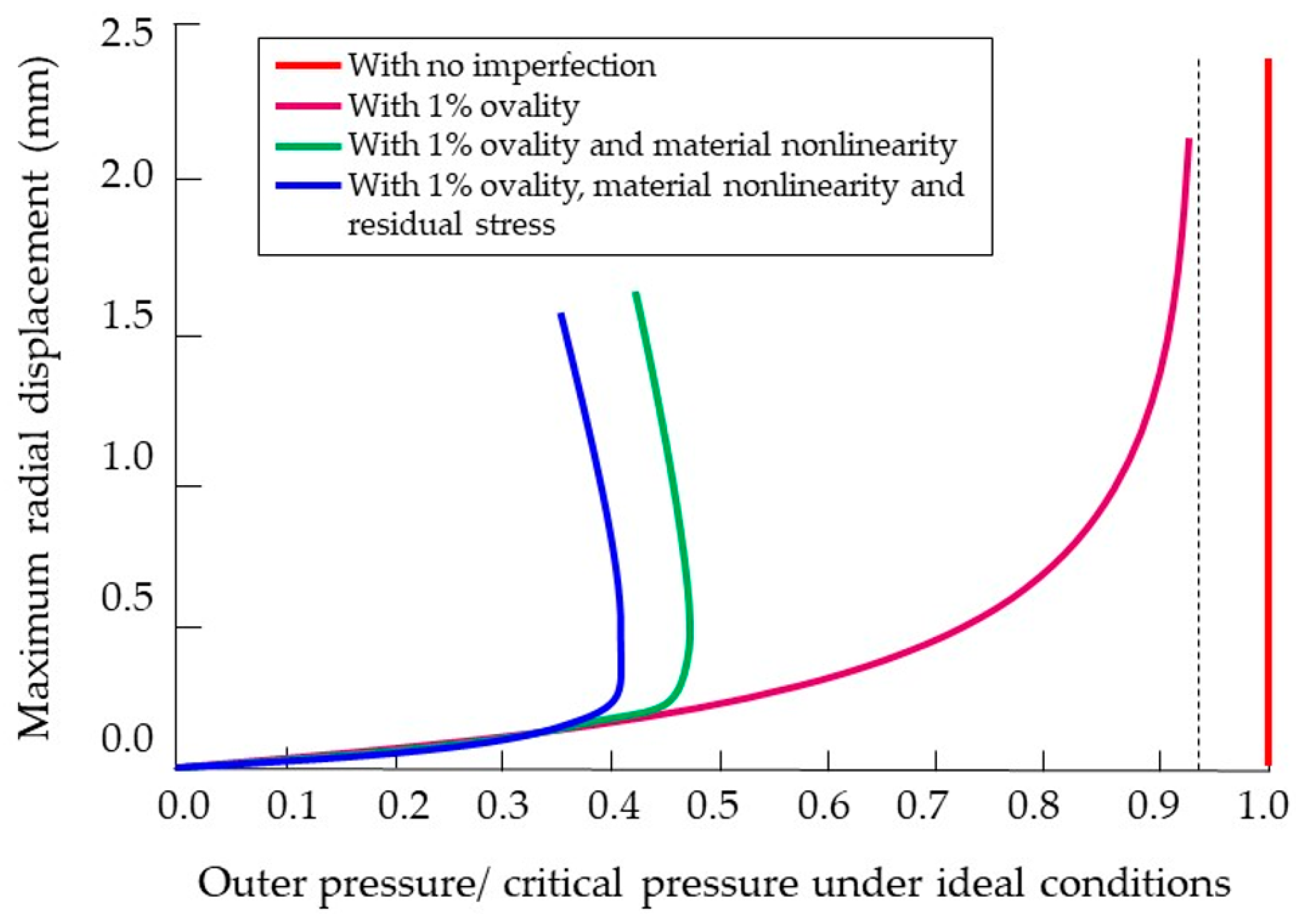
The buckling behavior of the carcass layer is calculated considering three types of imperfections, namely, geometric ovality, material nonlinearity and residual stresses from the deformation process, and compared with the results under ideal conditions, as shown in Figure 14. The transverse axis is the ratio of the applied external pressure to the first-order buckling eigenvalue of the carcass layer under ideal conditions, and the longitudinal axis represents the maximum radial displacement of the carcass layer. These indicate that the nonlinear buckling behavior of the carcass layer caused by different imperfections is different. As the imperfection increases, the critical pressure of the carcass layer gradually decreases. The quantitative impact of various imperfections on the critical pressure of the carcass layer structure is detailed in Table 1. It can be seen that when all the imperfections are considered simultaneously, the critical pressure of the carcass layer decreases by approximately 60% compared to the ideal results.
Figure 14.
Buckling behaviors of carcass layer with different imperfections.

Table 1.
A comparison of the critical pressure resulting from the model considering different imperfections.
When only the geometric ovality is considered, the pressure–displacement curve gradually approaches the critical pressure value, the decrease in which, relative to the ideal results, is relatively small (less than ten percent). If material nonlinearity is considered simultaneously, the buckling behavior of the carcass layer exhibits a typical ultimate buckling form, with the critical pressure decreasing by nearly 50%. This indicates that material characteristics significantly weaken the buckling resistance of the carcass layer. When further considering the residual stresses induced by the deformation process of the carcass layer, a similar ultimate buckling form is observed, but the critical pressure decreases by an additional 8%. This underscores the importance of considering residual stresses due to deformation in predicting the nonlinear buckling behavior of the carcass layer.
5. Conclusions
In this study, the cold bending forming process and principles of the carcass layer of offshore flexible pipelines are provided, and a three-dimensional finite element numerical model is established utilizing shell elements. The process of bending the steel strip using a series of rollers and the process of interlocking the S-shaped steel strip using four sets of radial pressure rollers are dynamically simulated, enabling the calculation of the structural deformation and residual stresses during the complete cold bending deforming process of the carcass layer. The cross-section of the formed carcass layer agrees well with the designed shape, confirming the accuracy of the proposed finite element model.
Taking the carcass layer structure of the flexible pipeline with a 4-inch internal diameter as an example, the three-dimensional finite element model of the carcass layer structure is developed considering various imperfections, including residual stresses due to deformation, and the nonlinear buckling behavior and critical pressure of the carcass layer are analyzed.
The study results show that when considering both geometric ovality and material nonlinearity, the structure exhibits a significant ultimate buckling form, and the critical pressure is approximately half that under ideal conditions, with the material properties notably weakening the buckling resistance of the carcass layer. When the residual stresses due to deformation are further considered, the ultimate buckling form remains unchanged, but the critical pressure decreases by about 8%, indicating that the influence of residual stresses on the nonlinear buckling behavior of the carcass layer cannot be ignored. The finite element model presented in this study provides an effective technical tool for accurately predicting the buckling resistance of flexible pipelines in actual engineering.
Author Contributions
Conceptualization, M.T.; Methodology, M.T.; Software, Z.G.; Validation, M.T.; Investigation, W.Z.; Resources, Z.G.; Data curation, W.Z.; Writing—original draft, M.T.; Writing—review & editing, F.W.; Visualization, F.W. All authors have read and agreed to the published version of the manuscript.
Funding
This work was supported by the National Natural Science Foundation of China (Grant No. 51709242) and the National Key Research and Development Program (Grant No. 2021YFC2801602). The authors would like to express their gratitude.
Institutional Review Board Statement
Not applicable.
Informed Consent Statement
Not applicable.
Data Availability Statement
Data are available upon request due to restrictions. The data presented in this study are available upon request from the corresponding author. The data are not publicly available due to data security management regulations of China Ship Scientific Research Center.
Conflicts of Interest
The authors declare no conflicts of interest.
References
- Report of Committee V.8: Risers and pipelines. In Proceedings of the International Ship and Offshore Structures Congress (ISSC), Lisbon, Portugal, 7–10 September 2015.
- Yue, Q.J.; Lu, Q.Z.; Yan, J. Tension behavior prediction of flexible pipelines in shallow water. Ocean Eng. 2013, 58, 201–207. [Google Scholar] [CrossRef]
- Tang, M.G.; Yang, C.; Yan, J. Validity and limitation of analytical models for the bending stress of a helical wire in unbonded flexible pipes. Appl. Ocean Res. 2015, 50, 58–68. [Google Scholar] [CrossRef]
- Yan, J.; Ying, X.P.; Bu, Y.F. Summary of development of flexible riser structural technology in deep water. Ocean Eng. Equip. Technol. 2019, 6, 745–749. [Google Scholar]
- Zhang, Y.; Chen, B.; Qiu, L. Analytical tools optimize unbonded flexible pipes for deepwater environments. J. Pet. Technol. 2004, 56, 48–58. [Google Scholar]
- Tang, M.G.; Lu, Q.Z.; Yan, J. Buckling Collapse Study for the Carcass Layer of Flexible Pipes Using a Strain Energy Equivalence Method. Ocean Eng. 2016, 111, 209–217. [Google Scholar] [CrossRef]
- Wang, W.; Chen, G. Analytical and numerical modeling for flexible pipes. China Ocean Eng. 2011, 25, 737–746. [Google Scholar] [CrossRef]
- Gay Neto, A.; de Arruda Martins, C. A comparative wet collapse buckling study for the carcass layer of flexible pipes. J. Offshore Mech. Arct. Eng. 2012, 134, 031701–031709. [Google Scholar] [CrossRef]
- Pang, G.L.; Chen, C.H.; Shen, Y.J. Equivalent calculation of critical collapse pressure of flexible pipes and parametric analysis of collapse influence factors. J. Pipeline Syst. Eng. Pract. 2021, 12, 04020062. [Google Scholar] [CrossRef]
- Timoshenko, S.P.; Gere, J.M. Theory of Elastic Stability, 2nd ed.; Courier Corporation: North Chelmsford, MA, USA, 1961. [Google Scholar]
- Nogueira, V.P.P.; Netto, T.A. A Simple Alternative Method to Estimate the Collapse Pressure of Flexible Pipes. In Proceedings of the ASME 29th International Conference on Ocean, Offshore and Arctic Engineering, Shanghai, China, 6–11 June 2010. [Google Scholar]
- Chen, Y.F.; Liu, H.; Cao, J. Collapse failure of carcass for unbonded flexible pipe considering axial loading and external pressure. Ocean Eng. 2022, 40, 125–133. [Google Scholar]
- Gay Neto, A.; de Arruda Martins, C.; Malta, E.R. Simplified finite element models to study the wet collapse of straight and curved flexible pipes. J. Offshore Mech. Arct. Eng. 2017, 139, 061701. [Google Scholar] [CrossRef]
- Liu, M.E.; Yang, L.; Fan, J.K. Analysis of multi-pass cold bending process for carcass layer of deepwater flexible pipeline. Die Mould Technol. 2021, 40, 40–47. [Google Scholar]
- Meniconi, S.; Brunone, B.; Tirello, L. Transient tests for checking the Trieste subsea pipeline: Towards the field tests. J. Mar. Sci. Eng. 2024, 12, 374. [Google Scholar] [CrossRef]
- Meniconi, S.; Brunone, B.; Tirello, L. Transient tests for checking the Trieste subsea pipeline: Diving into fault detection. J. Mar. Sci. Eng. 2024, 12, 391. [Google Scholar] [CrossRef]
- Tang, M.G.; Wang, Y.; Yan, J. Finite element analysis for collapse of flexible pipes carcass. J. Harbin Eng. Univ. 2013, 34, 1135–1140. [Google Scholar]
- Yu, T.X. Engineering Plasticity Mechanics, 2nd ed.; Higher Education Press: Beijing, China, 2010. [Google Scholar]
- Zhu, J.F.; Wang, H.; Xu, S.L. Nonlinear Finite Elements and Their Application in the Design of Aircraft Structures, 2nd ed.; Shanghai Jiao Tong University Press: Shanghai, China, 2012. [Google Scholar]


Disclaimer/Publisher’s Note: The statements, opinions and data contained in all publications are solely those of the individual author(s) and contributor(s) and not of MDPI and/or the editor(s). MDPI and/or the editor(s) disclaim responsibility for any injury to people or property resulting from any ideas, methods, instructions or products referred to in the content. |
© 2024 by the authors. Licensee MDPI, Basel, Switzerland. This article is an open access article distributed under the terms and conditions of the Creative Commons Attribution (CC BY) license (https://creativecommons.org/licenses/by/4.0/).