Review

Review of Implosion Design Considerations for Underwater Composite Pressure Vessels

by
Helio Matos
*,
Akongnwi Nfor Ngwa
,
Birendra Chaudhary
and
Arun Shukla
Dynamic Photomechanics Laboratory, Department of Mechanical Industrial and Systems Engineering, University of Rhode Island, Kingston, RI 02881, USA
*
Author to whom correspondence should be addressed.
J. Mar. Sci. Eng. 2024, 12(9), 1468; https://doi.org/10.3390/jmse12091468
Submission received: 31 July 2024 / Revised: 14 August 2024 / Accepted: 22 August 2024 / Published: 23 August 2024
(This article belongs to the Special Issue Structural Analysis and Failure Prevention in Offshore Engineering)

Abstract

:
The implosion of underwater composite structures is a critical and complex engineering problem, necessitating high-strength, lightweight, and corrosion-resistant materials for deep-sea applications. This manuscript reviews the intricate failure mechanisms of composite structures, focusing on cylindrical structures under extreme underwater conditions. The recent Titan submersible implosion serves as a case study, highlighting the significance of rigorous design considerations. Key topics include material degradation, buckling instability, and material failure, with a detailed analysis of composite layup optimization and manufacturing processes such as filament winding and roll wrapping. The manuscript underscores the need for comprehensive testing, advanced simulation techniques, and monitoring system integration to ensure the safety and effectiveness of composite pressure hulls. Future research should focus on developing more accurate failure models, optimizing manufacturing processes, and enhancing material properties through innovations in composite science to realize the full potential of composite materials in deep-sea applications.

1. Introduction

The implosion of underwater composite structures presents a complex and critical problem in engineering. Composite structures offer numerous advantages over metallic counterparts, including high strength-to-weight ratios, corrosion resistance, and reduced magnetic and thermal signatures, making them increasingly popular for underwater applications [1]. However, these benefits are counterbalanced by the intricate failure mechanisms unique to composites, which complicate design and analysis. Implosion failure in composite structures can be attributed to several factors, which include material strength and strength degradation (due to salinity and water ingress), flaws leading to fracture, buckling from instability, fatigue, pressure gradients (from shock waves or rapid depressurization), and temperature variations (fluctuations that induce thermal stresses) [2]. These failure mechanisms necessitate a comprehensive understanding of composite systems and precise engineering to ensure structural integrity and safety under extreme underwater conditions [3,4].
Recent accidents, such as the implosion of the Titan submersible in June 2023, are harsh reminders of the critical importance of rigorous design considerations for underwater composite structures. The pressure hull for the Titan, operated by OceanGate, was constructed primarily from carbon fiber and titanium. Critics speculate that the composite hull design was a major contributing factor to the submersible’s catastrophic failure [5,6,7]. The implosion process of composite materials is influenced by the specific architecture and layup of the composite, as well as the environmental conditions to which the material is exposed. Studies have shown that the critical collapse pressure and the nature of the implosion vary significantly between different composite configurations and environmental conditions [4,8]. The lack of design guidelines for composite pressure hulls and comprehensive understanding, especially under extreme loading conditions, poses significant challenges [1].
In recent years, much work has been performed analyzing buckling-initiated implosions of composite structures [2,9,10,11]. Buckling can occur due to the inherent anisotropy and heterogeneity of composite materials (meaning that they depend on ply layup and orientation), making them susceptible to instability under compressive loads. The critical buckling pressure of a composite structure depends on its geometric parameters, material properties, and the nature of the applied load [12,13]. Experimental studies have shown that the buckling behavior of composite structures can be significantly different from that of metallic structures, requiring specialized design approaches [4,12]. Analytical and computational solutions can accurately predict buckling pressures [2,10,14,15]. Composite structures that typically fail from instability are relatively thin-walled [16]. Hence, this type of failure may be prominent in pressure hulls designed for shallow water.
For application in deep-sea environments, pressure hulls will typically be thick-walled, which leads to the material failing before buckling can initiate. Material failure mechanisms in composites can be complex, involving multiple failure modes such as matrix cracking, fiber breakage, and interfacial debonding [3,16]. Material failure–initiated implosions are inherently more difficult to predict than buckling-initiated implosions due to the need for a robust failure model. With such a failure model, the material failure–initiated implosions could be modeled computationally. However, developing robust failure models for composites requires significant effort in testing the materials and expertise to develop these models. Modeling composite failure is challenging and requires significant resources. Because of this, most numerical models tend to simplify the composite and failure models to ease the design complexities, adding risk to the design. These design approaches must be revised for high-risk extreme environments like the deep sea.
This review discusses the different implosion mechanisms and design considerations for these different implosion mechanics at a high level. The focus will be on analyzing cylindrical structures for buckling and material failure, but some discussions will also be made regarding other failure initiation mechanisms. This review highlights the intricate failure mechanisms of composite structures, which demand meticulous design and optimization to harness their advantages for underwater applications while ensuring robustness against implosion. By reviewing these topics and presenting the intricate mechanisms specific to composite implosions, we hope to prevent future catastrophes like the Titan submersible, which is also presented as a case study in this review

2. Background

2.1. Evolution of Composite Pressure Hulls

Developing composite materials for deep-sea applications began in earnest during the late 20th century. Initial studies focused on small glass/epoxy cylinders, with research efforts expanding to include carbon/epoxy composites. These studies were driven by the need for lighter and stronger materials to withstand the extreme pressures at great ocean depths [17]. We have buoyancy with submersibles, so unlike an aircraft, they do not need to constantly struggle to maintain their vertical position underwater. However, lighter structures can make the submersible more energy efficient, as Newton’s second law shows that a higher mass reduces maneuverability for the same propelling and drag forces. In the 1980s, the application of composite pressure hulls in underwater environments gained significant attention, especially for submersibles and other underwater vehicles. Researchers identified that as diving depths increase, the structural integrity of these composite pressure hulls poses unique challenges [18].
Further advancements in the field were marked by introducing nondestructive testing (NDT) techniques and long-term behavior studies under hydrostatic pressure. These efforts aimed to ensure the reliability and durability of composite materials in underwater environments. For instance, European research programs have extensively tested thermosetting and thermoplastic matrix composites to failure, exploring the influence of defects and impact damage on implosion pressures [17]. Significant milestones include the development of autonomous underwater vehicles (AUVs), underwater gliders, and human-occupied vehicles (HOVs) utilizing composite materials [18], as illustrated in Figure 1. Integrating composites into pressure hulls has also spurred the development of hybrid structures combining composite materials with metals [2]. Such innovations aim to leverage the benefits of both material types [17]. Despite these advancements, predicting conditions for the implosion of composite pressure hulls still presents significant challenges for deep-sea applications.

2.2. Choosing Composites

Composite materials ultimately allow for the construction of lightweight structures, reducing energy requirements and improving performance [17]. However, using composites also presents several drawbacks and challenges that must be addressed during the design process. Manufacturing composite structures are more complex and require meticulous control to avoid defects such as delamination and voids, which can significantly reduce mechanical performance [18]. Additionally, composites tend to fail in a brittle manner, meaning that they may exhibit less warning before catastrophic failure than ductile metals [18]. Moreover, fiber-reinforced composite structures have lower fracture properties, such as fracture toughness, compared to traditional metals. They also possess failure mechanisms that are not present in metals, such as delamination [19,20]. Thus, composites have higher design challenges, complexities, and risks for deep-sea applications, where material failure is a key determining factor for operational depth.
Though composites do not corrode, the properties of composite materials will degrade over time due to environmental factors such as moisture absorption, ultraviolet radiation, and temperature variations [17]. Also, materials like carbon fiber are conductive and may unintentionally aid in the sacrificial corrosion of any metallic system attached and connected to the composite structure while exposed to seawater. Additionally, the raw materials and manufacturing processes for composites have been traditionally more expensive than metallic materials, impacting the upfront cost of the structure [18].
In contrast, metallic pressure hulls provide predictable failure modes, manufacturing simplicity, and cost-effectiveness (relative to composites). Metals generally exhibit more predictable and ductile failure modes, providing more warning signs before catastrophic failure [17]. Metal structures are more straightforward to manufacture, with well-established processes and standards, reducing the potential for defects [18]. Due to their easier design and predictability, metallic systems are inherently less risky than composite structures. These factors should be important considerations in the design process. Designers may need to prioritize performance over safety to justify the choice of composites over traditional materials by demonstrating that the benefits outweigh the risks.

3. Composite Pressure Hull Failure

Figure 2 illustrates the effects of hydrostatic pressure on a submerged structure, where the surrounding water exerts pressure on a cylindrical vessel, making it susceptible to hoop and axial stresses. When these stresses exceed a critical value, the structure will fail. It is important to note that a structure will have multiple critical pressure thresholds, each corresponding to different buckling modes or material failure thresholds. The lowest of these critical values determines the depth at which the submersible will first experience failure, and this value can be set as the submersible’s critical depth. The right side of Figure 2 shows a cross section of a cylinder undergoing global buckling deformation after reaching its critical buckling pressure. On the left side, a material failure–implosion is depicted, where localized stress exceeds the material’s critical threshold, leading to failure at a structural flaw.
In the absence of pressure or temperature fluctuations and without accounting for material degradation, implosion is predominantly cause by either buckling or material failure, depending on which failure mechanism has the lower critical threshold. These are the primary failure modes discussed in this paper.

3.1. Buckling Failure

Composite Buckling Solution
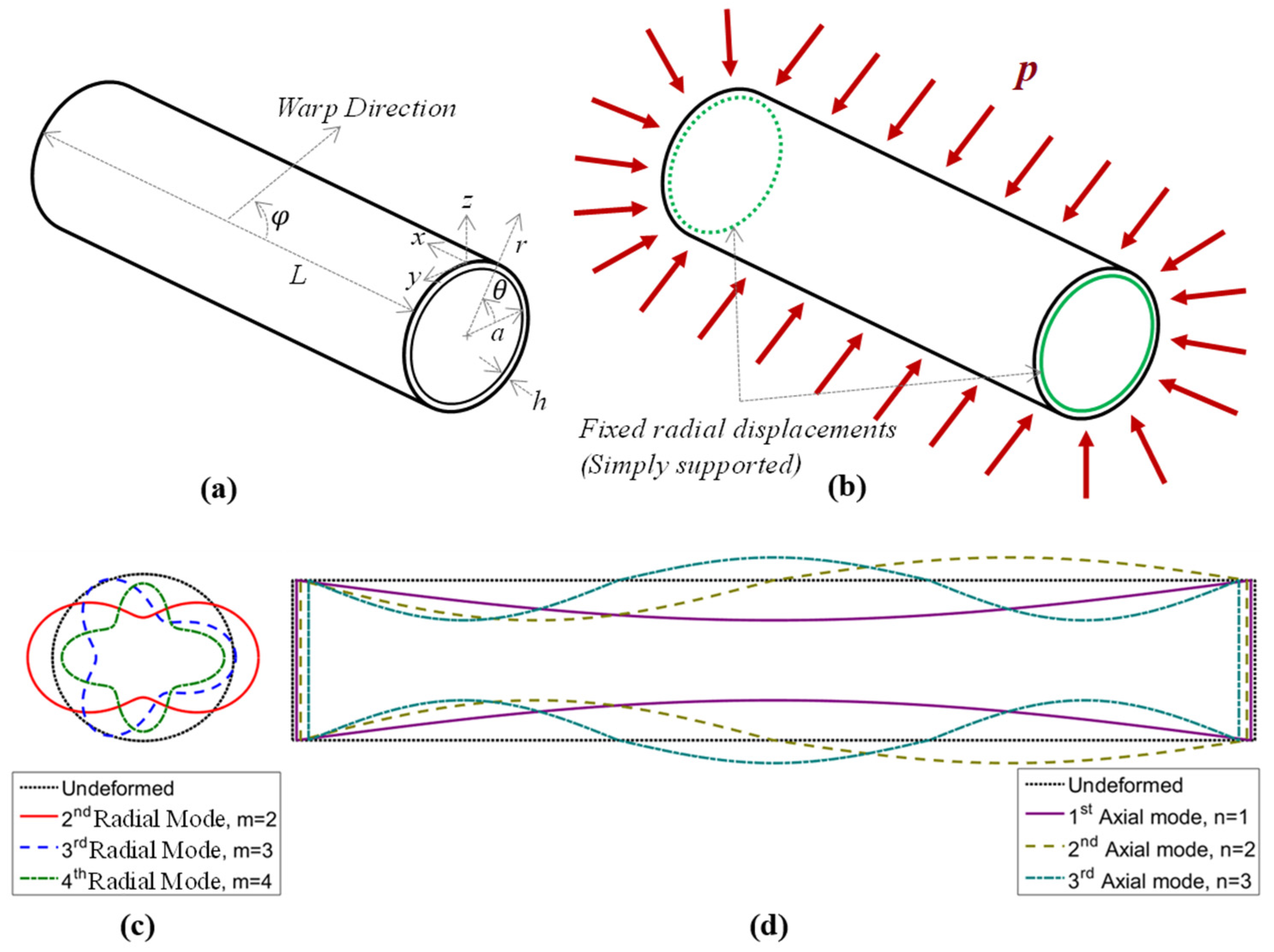
A key indicator may be the relative size (diameter) to the structure’s thickness to determine if a structure will fail due to buckling. If this ratio is large, then the structure can be considered “thin-walled” or “shells” and will tend to fail from buckling instability. For pressure hull structures, this means that structures designed for shallow waters will tend to buckle in shallow-water applications before the material can fail due to high stresses. During buckling failure, the structure will deform globally in a symmetric deformation mode. Furthermore, the material model can be simplified for design purposes with the plane stress assumption, in which in-plane properties are dominant, making the composite laminate sufficient to model buckling problems [10]. Using composite laminate theory, the forces (Nij and Ki) and moments (Mij) within a composite structure can be found as a function of strains ( ε i j and γ i j ), curvatures (kij), and a structural stiffness matrix using Equation (1).
N x N y N x y M x M y M x y K x K y = A 11 A 12 A 16 B 11 B 12 B 16 0 0 A 12 A 22 A 26 B 12 B 22 B 26 0 0 A 16 A 26 A 66 B 16 B 26 B 66 0 0 C 11 C 12 C 16 D 11 D 12 D 16 0 0 C 12 C 22 C 26 D 12 D 22 D 26 0 0 C 16 C 26 C 66 D 16 D 26 D 66 0 0 0 0 0 0 0 0 F 44 F 45 0 0 0 0 0 0 F 45 F 55 ε x ε y γ x y k x k y k x y γ x z γ y z
where A i j , B i j , C i j , D i j , and F i j are components of a composite’s stiffness matrix (often referred to as the ABD stiffness matrix). Each matrix element is calculated as a function of the structure’s geometry (ply location) and material properties. Then, combining the laminate material model with the equilibrium equations of a cylinder and applying small deformation theory, the solution for a composite laminate buckling can be found using Equation (2), and illustrated in Figure 3. Further details can be found in previous work [10,16] as well as in most composite mechanics manuals.
p c r = β β 2 4 α δ 2 α
where
  • α = U 1 ϕ 2 ϕ 3 + U 2 ϕ 1 ϕ 3 + U 3 ϕ 1 ϕ 2 m
  • β = U 1 V 2 ϕ 3 + W 3 ϕ 2 + U 2 V 1 ϕ 3 W 3 ϕ 1 + V 3 ϕ 1 m + U 3 W 1 ϕ 2 + W 2 ϕ 1 V 2 ϕ 1 m
  • δ = U 1 V 2 W 3 V 3 W 2 + U 2 V 3 W 1 V 1 W 3 + U 3 V 1 W 2 V 2 W 1
  • ϕ 1 = a π n m L
  • ϕ 2 = a b 2 π 2 n 2 L 2
  • ϕ 3 = m 2 + a b 2 π 2 n 2 L 2 1
And
  • U 1 = π 2 n 2 L 2 a A 11 + m 2 a A 66
  • V 1 = π n m L A 12 + A 66 + 1 a 2 B 66 B 12
  • W 1 = π n L A 12 + m 2 a 2 B 66 B 12 π 2 n 2 L 2 a B 11
  • U 2 = π n m L A 12 + A 66 + 1 a C 66 C 12
  • V 2 = π 2 n 2 L 2 a A 66 + 2 B 66 + C 66 + 2 a D 66 + m 2 a 2 a A 22 B 22 C 22 + 1 a D 22
  • W 2 = m a 2 a A 22 C 22 + π 2 n 2 m L 2 2 B 66 B 12 + 1 a D 12 + 2 D 66 + m 3 a 3 D 22 a B 22
  • U 3 = π n L A 12 π 2 n 2 L 2 a C 11 m 2 a C 12 2 C 66
  • V 3 = m a 2 a A 22 B 22 + π 2 n 2 L 2 m a 2 a C 66 a C 12 + D 12 + 4 D 66 m 3 a 3 a C 22 D 22
  • W 3 = 1 a A 22 π 2 n 2 L 2 B 12 + C 12 m 2 a 2 C 22 + B 22 + π 4 n 4 L 4 a D 11 + π 2 n 2 m 2 L 2 2 a D 12 + 2 D 66 + m 4 a 3 D 22
Figure 3. (a) Composite tube schematic, (b) hydrostatic pressure loading and simple support boundary conditions, (c) radial deformation modes, and (d) axial deformation modes [16].
Jmse 12 01468 g003
The solution presented in Equation (2) is relatively long because it makes no assumptions regarding the symmetry of the composite layup and simplified properties for composites, which are typically performed, though not always appropriate assumptions. From industry design standards, one of these simplified solutions is the one presented by the American Society of Mechanical Engineers [21] for composite pressure vessels. This standard, if properly used, works well for design after introducing a knockdown factor (KD). The KD is an empirical parameter that is introduced to the equation to fit the solution in the lower bound of the experimental observations that were performed during the development of the solution. In essence, KD compensates for the oversimplifications, but being in the lower bound of experimental observations for collapse depth is good for design purposes. However, there are limitations on empirical solutions which should be considered prior to their use. These limitations lie within the constraints of the data used to obtain the fitting parameters.
An important detail in the ASME guidelines that may be overlooked is the recommended Safety Factor of 5. While this Safety Factor is high compared to general design standards, it underscores the complexity and uncertainty involved in using composite systems under extreme conditions, necessitating an overly conservative design approach. However, such a conservative approach can also result in lower performance than a less conservative design. As a result, the performance gains of switching from a standard metallic structure to a highly conservative composite structure may not be as significant as initially expected when justifying the use of composites. Therefore, the widespread adoption of composites in such demanding environments will require less conservative designs, which in turn will necessitate higher quality and reliability in the modeling and manufacturing of composites than current standards and guidelines provide.

3.2. Material Failure

Previous work [16] explained that the cylinder’s diameter-to-thickness ratio can be a key indicator of the type of failure that will be dominant. Instability failure mode generally occurs in tubes with a D/t ratio greater than 20, while material failure typically occurs in tubes with a D/t less than 20. There is a gray area regarding where the threshold for transitioning from buckling to material failure is because more factors could influence the implosion. However, in general, tubes with a D/t less than 20 are considered as “thick-walled” structures, and tend to fail due to material failure [16]. For deep-sea applications, where D/t ratios are small, the structure’s material will tend to fail before it can buckle [16]. A plane stress assumption and the composite laminate theory from Equation (1) are not appropriate for thick-walled structures. Thick materials will have a three-dimensional behavior for forces, moments, and shear, leading to a system of equations with 15 components (instead of 8 from Equation (1)) to model the structure’s linear elastic behavior.
In addition, as the name of this type of failure implies, a composite damage and failure model would also be needed to account for the possible failure mechanisms. Many of these failure mechanisms are discussed in a previous review article on this very topic [18]. Robust failure models, such as MAT213 from LS-DYNA [22], require a high level of composites expertise to be adapted into an analysis. In addition, these types of models require extensive effort for model calibration and validation and are material and manufacturing method-specific. Hence, these are not universal models, and it is relatively expensive to adapt them. For this reason, the modeling work tends to simplify the composite structures’ behavior to circumvent the additional complexities and costs. Similar to previous discussions, oversimplifications will add to the risk of the design, which in turn would require overly conservative designs to compensate for such risks.
After material and failure models are calibrated and validated, the thick-walled pressure vessel design approach can be applied. This theory focuses on maximum loads rather than instability. Due to the complexities of material modeling, computational numerical tools are equipped to handle this better than analytical closed-form solutions. For noncontinuous fiber composites, such as chopped fiber composites, the material model and analysis can be simplified (to an isotropic model) such as how it was performed in previous work by Chaudhary et al. [23] to derive an analytical solution, illustrated in Figure 4 and given by Equation (3). One of the takeaways from this solution is that there is a higher scatter in the collapse pressure from material failure–driven implosions [23] than in buckling-initiated implosions [24]. This alludes to an inherently higher risk factor for deep-sea applications than shallow-water applications for composite pressure hulls. There is a lot of uncertainty with these higher risks, and more research work is needed regarding the use of composites for deep-sea applications and material-driven composite implosions before adequate standards can be formed and composite pressure hulls can become a viable option for wide adoption in deep-sea applications.
P c r = σ u ( r o 2 r i 2 ) r i 4 + r o 4 + r o 2 r i 2  

3.3. Material Degradation

While corrosion is not a primary concern for composite materials used in underwater pressure hulls, their performance can degrade over time due to exposure to environmental factors such as UV radiation, seawater, and temperature variations. For underwater pressure hulls, degradation from seawater exposure is a significant concern. This type of degradation occurs primarily through the diffusion of water into the epoxy matrix of the composite material, leading to swelling, fiber/matrix debonding, and delamination. Studies have shown that such exposure can result in a marked decrease in the mechanical properties of composites [25,26].
The degradation process involves the water molecules diffusing into the composite material, which increases internal stresses and diminishes the mechanical properties, such as the shear modulus and compressive strength. Accelerated aging tests are often employed to simulate long-term environmental exposure within a shorter timeframe, typically using elevated temperatures to accelerate water diffusion. Techniques such as Arrhenius’ equation calculate the activation energy and determine an acceleration factor, which relates the elevated temperature conditions to normal service conditions [17,27].
To account for this degradation during the design process of composite pressure hulls, engineers must conduct rigorous accelerated life testing, submerging composite samples in saline water baths at elevated temperatures to measure changes in mechanical properties over time [25]. During the design process, the material model used should be for the material in its degraded state at the end of its operational life. Beyond that, protective coatings can also be incorporated into the design to mitigate the effects of environmental exposure, significantly reducing water absorption and slowing the degradation process, thereby enhancing the durability of composite structures in marine environments [23].

3.4. Pressure Gradients

Pressure perturbations, such as those caused by dynamic shockwaves, can lead to the premature failure of composite pressure hulls at subcritical design pressures. Shockwaves from underwater explosions or other dynamic events generate high-magnitude pressure pulses that travel through the hull material. These pressure pulses can cause localized stress concentrations, leading to potential microcracking, fiber–matrix debonding, and delamination. This phenomenon is particularly concerning for composite materials, which may not exhibit the same level of ductility and warning signs before failure as metallic structures. Also, composites have a mechanical impedance closer to water than metallics, leading to relatively higher-pressure wave transmissions within the material when interacting with dynamic loads, in turn having a higher risk factor for the same level of dynamic loading. When a composite pressure hull is subjected to such perturbations, the resulting damage accumulation weakens the structure and reduces its overall performance. This can result in catastrophic failure well below the intended design pressure [25].
Experimental studies have shown that the magnitude and frequency of the applied perturbations can significantly influence the implosion of composite cylinders. Strong shockwaves can cause immediate collapse and material failure in a structure designed for buckling failure. Weaker perturbations may lead to gradual damage accumulation, or they could resonate with the structure, ultimately resulting in failure from material failure or buckling [28]. To account for these effects during the design of composite pressure hulls, the industry design guidelines are to adopt robust safety factors in a design for static loading. Unlike metallics, composites often have time-dependent properties, which makes designing the structure under simulated dynamic loading conditions challenging. Engineers must also consider mitigation techniques, such as the use of protective coatings and other reinforcement methods to enhance the resilience of composite materials against dynamic pressure perturbations [17,19,26,29].

3.5. Temperature Fluctuations

Temperature fluctuations can significantly affect the performance and longevity of composite structures [22]. However, in the context of underwater pressure hulls, this concern is typically mitigated by the nature of the marine environment. The infinite thermal mass of the ocean ensures that at any specific depth, the water temperature remains relatively constant, thus providing a stable thermal environment for submerged structures. This stability helps maintain the structural integrity of composite pressure hulls, because they are not subjected to the thermal stresses that arise from rapid temperature changes [22]. However, it is often overlooked that when a submersible changes depth, it can encounter different temperature layers. Such thermal gradients can introduce thermal stresses on top of the changing pressure stresses, potentially leading to microcracking, matrix shrinkage or expansion, and differential thermal expansion between the fibers and the matrix. These stresses can accumulate over time, potentially degrading the material’s mechanical properties and leading to premature failure. Figure 5 illustrates this temperature variation for tropical, mid-latitude, and polar regions. Except for the polar regions, a drastic temperature decrease exists from 0 to 500 m depth.
The mechanical performance of polymer composites is temperature-dependent. They generally become more brittle with a decrease in temperature (decrease in failure strain). The elastic modulus and failure strength of carbon fiber composite in compression can decrease by up to 30% at −2 °C when compared to room temperature [30]. Furthermore, composite structures are composed of two or more materials, each with different thermal expansion coefficients, making thermal stresses more of a concern for composite structures than traditional metals. Despite the potential impact, relatively limited research has focused on the effects of temperature and temperature fluctuations on composite pressure hulls. More studies are needed to simulate and analyze this behavior to identify potential failure mechanisms and develop strategies to enhance the thermal resilience of composite pressure hulls.

3.6. Fatigue

Fatigue loading in composite pressure hulls is also overlooked because submerging and resurfacing processes are typically slow, resulting primarily in hydrostatic pressure loads. However, over the operational lifespan of a pressure hull, which can span many years, these vessels are subjected to a potentially significant number of pressure cycles. During each cycle, the structure’s walls deform because of increased and decreased external pressure during the descent and resurfacing, respectively. Each cycle contributes to gradual damage accumulation, potentially leading to fatigue failure. Despite the significance of fatigue loading on long-term use, limited research specifically addresses its impact on composite pressure hulls. Future work could be performed on predictive models that account for cumulative damage from repeated pressure cycles and environmental influences for long-term applications.

4. Design of Composite Pressure Hulls

4.1. Material Selection

When selecting materials for a composite pressure hull, it is crucial to consider their mechanical properties, such as compressive strength, modulus of elasticity, and failure strain. Carbon fiber–reinforced polymer composites (CFRPs) are preferred for their significantly higher tensile modulus and strength. They are ideal for applications where rigidity and load-bearing capacity are paramount, such as deep-sea applications for composite pressure hulls. On the other hand, glass fiber–reinforced polymer composites (GFRPs) offer higher failure strains and are more cost-effective, making them suitable for applications requiring a balance between performance and budget [2,17,26,28], potentially for shallow water applications.
Other possibilities include hybridizing composite systems, which can leverage the benefits of different materials. For instance, using thicker glass fiber plies for inner layers and stiffer carbon fiber plies for outer layers can optimize the buckling collapse pressure, providing superior flexural rigidity and overall structural performance [2]. Hybridization offers more flexibility and tailoring of the pressure hull performance but adds more complexities to the design and manufacturing. In addition to mechanical properties, other factors such as manufacturability and nonmechanical properties like thermal and magnetic transparency may influence material selection. While these factors are beyond the scope of this discussion, they are important considerations in the holistic design process of composite pressure hulls [2,26].

4.2. Accounting Failure

Design engineers must meticulously consider all potential failure mechanisms when designing composite pressure hulls. The process begins with analyzing the composite design for all implosion initiation mechanisms, which include instability (buckling) and material failure to ensure safety and reliability; the maximum operational depth should be set to the lowest depth determined from these analyses [2].
Assessing the composite hull’s structural stability, as discussed in Section 3.1, is crucial to addressing buckling failure. Buckling analysis is typically the first step, as information about the elastic material properties can be estimated with relatively high confidence through micromechanical composite models and relations for an initial rough design. After initial design and material selection, material testing should be conducted for a reliable material model. Then, to address material failure, as discussed in Section 3.2, engineers must also develop an appropriate material failure model during the testing effort. Further, thick composites will require additional testing that accounts for 3D tension and compressive stress states. Degraded material models should also be considered for long-term applications. For applications where composites are at operational depths for prolonged periods, creep failure should also be part of the material failure model. After these models are developed, they can be applied to computation tools, such as a nonlinear Riks failure analysis, to reevaluate the initial design, but now with a validated, reliable material model that accounts for failure. A composite expert is needed throughout this process, which is tedious and comprehensive for composite systems, and design book standards are insufficient for these analyses. Furthermore, modeling composite structures can be challenging, and adequate models for thick composites, which would require 3D elements, is a research challenge, and not yet streamlined for industrial use.
When considering dynamic pressure environments, such as those caused by underwater explosions or sudden impacts, the design should also account for the potential dynamic energy input, as these dynamic loadings can cause microcracking and induce several other defects through localized stress concentrations. Engineers must conduct simulations of these dynamic conditions to design for survivability in subcritical pressure environments [26]. Lastly, after all loading conditions are accounted for, simulations still assume ideal operational conditions, so the design should also consider decorated conditions and an appropriate safety factor for long-term applications in extreme conditions [21].

4.3. Composite Layup Optimization

Layup optimization is a crucial aspect of designing composite pressure hulls, because it directly influences underwater vessels’ structural integrity, performance, and reliability [16]. One of the primary reasons for optimizing the layup is to enhance the strength-to-weight ratio of the pressure hull. Engineers can maximize the load-bearing capacity by strategically orienting the fibers while minimizing the overall weight [24,25]. The hull can achieve higher critical buckling loads by optimizing the ply orientation and stacking sequence, thereby increasing its stability and operational depth [2]. In dynamic pressure environments, such as those involving underwater explosions or impacts, the layup configuration plays a vital role in dissipating energy and preventing catastrophic failure. An optimized layup can distribute stress evenly and absorb energy more effectively, potentially reducing the risk of localized damage and subsequent structural collapse. Lastly, layup optimization allows for tailoring the mechanical properties to specific operational requirements. Different regions of the pressure hull may experience varying stress levels and environmental conditions.

4.4. Additional Considerations

Designing composite structures requires additional considerations beyond what this review has covered. These include manufacturing methods and quality control, the need for advanced monitoring systems, and standards beyond the design, such as the testing and validation standards for composite systems.

4.4.1. Manufacturing Methods

Two predominant methods for manufacturing composite tubes are filament winding and roll wrapping, as illustrated in Figure 6. Filament winding involves wrapping continuous fiber strands in tension around a rotating mandrel. These fibers are impregnated with resin during the winding process, which can be highly automated, allowing for precise control over fiber placement and orientation. This method is particularly advantageous for creating tubes with good structural integrity due to the continuous nature of the fibers, which ensures uniform stress distribution. Filament winding is ideal for producing large-diameter tubes and pressure vessels where seamless construction is essential. However, the equipment and setup costs can be high, and the process is less flexible regarding fiber orientation compared to roll wrapping (it cannot lay fibers in the length direction of the tube), which may limit some design capabilities [31,32].
On the other hand, roll wrapping involves laying prepreg (pre-impregnated) composite material layers onto a mandrel, as illustrated in Figure 6b. This process allows for more customization in fiber orientation, enabling engineers to design tubes with specific mechanical properties tailored to their application. Roll wrapping is beneficial for producing small to medium-sized tubes with complex layup configurations, providing excellent control over fiber orientation. Additionally, with roll wrapping, achieving high hoop strength often requires sacrificing some longitudinal rigidity, making this method less suitable for applications needing high stiffness along the tube’s length [33,34].
Regarding industry standards, filament winding is often preferred for applications requiring large, seamless structures, such as pressure vessels. This preference is due to its ability to produce highly reliable and consistent tubes with minimal defects. Roll wrapping is widely used in industries where customization and specific mechanical properties are crucial, such as sporting goods, medical devices, and smaller aerospace components. The choice between these methods depends on the application’s requirements [32,34]. However, filament winding will yield the best quality for fiber-reinforced composites due to its seamless integration and precise automated controls.

4.4.2. Performance Monitoring

Implementing a monitoring system for composite structures is essential for maintaining their integrity and ensuring safety. Monitoring can be in the form of active inspections via nondestructive testing (NDT), which is the industry standard, or smart systems like structural health monitoring (SHM), which offer real-time structural performance data. Monitoring will enabling early detection of damage such as cracks, delamination, and fiber breakage [35]. This early detection is crucial for preventing catastrophic failures, which can have severe consequences in critical applications. For instance, in aerospace, where over 50% of aircraft structures are made from composites, SHM can prevent accidents by detecting flaws before they become critical [36,37,38].
The benefits of SHM systems are manifold. They enhance safety by providing continuous, real-time monitoring, allowing timely maintenance and repairs. This reduces downtime and maintenance costs, as inspections can be performed based on actual conditions rather than scheduled intervals. Moreover, SHM systems can extend the lifespan of composite structures by ensuring that they operate within safe limits and by optimizing the usage of materials based on their performance data [37,39]. Techniques such as embedding fiber optic sensors (FOSs) within composite materials have shown promise due to their high sensitivity, immunity to electromagnetic interference, and ability to provide distributed sensing over large areas [36]. However, it is important to note the limitations to SHM, which is that they provide a measurement of current performance (where sensors are located) and current performance is not indicative of future behavior. NDT is more utilized for evaluation and validation since it is adaptable to different circumstances.

4.4.3. Testing and Safety Standards Post Initial Design

To ensure the reliability of composite pressure hulls, it is essential to conduct comprehensive testing and simulations. This includes accelerated life testing under simulated environmental conditions, such as hydrothermal aging and cyclic loading tests, to assess long-term performance and durability [2,23,27]. Incorporating nondestructive evaluation techniques can also help monitor the integrity of the composite material throughout its service life.

5. Case Studies

5.1. Titan Submersible

The Titan submersible’s hull was constructed from carbon fiber/epoxy composites, with dimensions of 2.54 m in length and an outside diameter of 1.68 m. The hull’s total thickness was 127 mm (5 inches), comprising 480 plies of alternating unidirectional carbon fiber prepregs (for 0-degree layers—in the length direction) and filament wet-wound carbon fiber (for 90-degree layers—in the radial direction) [31], as illustrated in Figure 7. The service pressure was 44.82 MPa (6500 Psi) [31,40].
From the information available in news articles [31,40,41] and material manufacturers [42], the materials used for the hull included Grafil 37-800 carbon fiber and Epon resin 862 with Lindride LS-81K curing agent. Table 1 summarizes manufacturer properties. Using this public information, micromechanics principles [43,44]. The composite’s in-plane properties were estimated for different fiber volume fractions. Composites made from unidirectional prepregs (roll-wrapped tubes) can have a fiber volume fraction as low as 55%, while filament-wound tubes typically have a volume fraction of 65%. Because the Titan submersible comprises both construction methods, a fiber volume fraction of 60% was assumed. Nevertheless, the properties of the composites obtained using the fiber volume fractions of 55% and 65% are taken as the lower and upper limits for failure calculations, respectively. The in-plane properties considering a fiber volume fraction of 60% are estimated in Table 2. Further, assuming equal thickness within all layers of the structure, we can also estimate the composite structural components from Equation (1), as given in Table 2.
Using Equation (2) and the estimated properties from Table 2, we can calculate the expected buckling failure pressure of the hull to be 114 ± 10 MPa. The margins of error in the estimated buckling pressure comes from varying the fiber volume ration between 55% to 65% (only 60% ratio elastic property values are given in Table 2). The buckling failure pressure relative to the design depth pressure of 44.82 MPa suggests a buckling safety factor of 2.54 ± 0.22. This safety factor may be considered reasonable for general applications in harsh environments but guidelines like the ASME handbook suggests a value of 5 for pressure hull buckling applications [21].
The Titan hull could have failed due to instability or material failure. However, as explained in Section 3.2, the D/t ratio of 12.5 of the Titan submersible indicates the implosion initiated by material failure and not buckling. Assuming that is true, the material failure pressure could be much less than the estimated buckling pressure, indicating that the material failure safety factor is less than the estimated buckling safety factor of 2.54 ± 0.22. Direct testing of the material and more details about the construction would be needed to develop an accurate material model to estimate the material failure pressures precisely. However, the estimated buckling pressure and the resulting safety factor within general application standards indicate that material failure–initiated implosion may not have been accounted for during the design of the Titan pressure hull.
The composite layup of a (90/0)240 configuration indicates that layup optimization was also not performed. Standard pressure design handbooks often emphasize that structures are not subjected to a shear load during hydrostatic loading. However, these statements are only true for isotropic material structures and not composite layup structures. The Titan submersible would be subjected to shear forces for a length-to-diameter ratio (L/D) of 1.55. Figure 8 illustrates the optimal ply layup configuration for a unidirectional composite structure, where the modulus in the fiber direction is ten times greater than in the transverse direction—a characteristic typical of continuous carbon fiber unidirectional plies. In this configuration, Ply 1 represents the innermost ply, and Ply 5 represents the outermost ply. For a structure with an L/D ratio of ~1.5, the optimal configuration from the inner to outer plies includes layers designed to resist shear, hoop, axial, then hoop stresses. Hence, the general optimal layup configuration would include a shear-resisting layer (45°) at its innermost layers, hoop layers at 90°, axial layers near 0°, then transition to hoop layers in its outermost layers [16].
The exact lamina architecture would need to be known for the optimum configuration. However, a (90/0)240 configuration has little shear resistance through fiber reinforcement (predominantly performed by the matric alone) and would be susceptible to shear failure. Further, the construction method alternated between filament winding and roll wrapping, which may lead to the introduction of voids and discontinuities within the layers. The structure would be of higher quality if only filament winding were used; in this case, angles for axial resisting layers would come about with a thicker ±15° (relative to 0° layer). The angle limitations of filament winding are a good tradeoff for improved quality in the structure.
Note that the optimized layup in Figure 8 is for a thin-walled structure because it utilizes the buckling solution [16]. The buckling solution does give the stiffest tubular structure based on in-plane properties; hence, it could be used to rapidly come up with an initial optimized design based on in-plane properties; then, for material failure–initiated implosion, additional iterations would be required for validating or potentially further optimizing the design (using computational tools) to account for out-of-plane and failure properties.
The postmortem analysis of the Titian submersible indicated that the composite pressure hull was a likely cause (not definite) of the failure initiation [45]. Further, this high-level case study also shows much room for improvement in the design failure analysis and optimization. These mistakes are not brought to light to scrutinize the decisions that may have been on par with industry standards. However, it is important to identify crucial aspects and common oversights of composite designs that must be accounted for during the design process and highlight that handbook standards, such as the handbook standard from ASME [21], do not account for deep-sea applications. This means that more research and developmental work is needed before composite hulls can be safely used for such environments.

5.2. Other Implosion Failures

The Titan submersible failure was notable due to its publicity and consequences, but implosion has been an ongoing problem for decades [2,24,25,26,46]. Previous review articles also went over the history of composite implodables. They further highlighted the need for better composite pressure hull design approaches to prevent failures for deep-sea applications [18]. Recent studies also highlighted the sensitivity of composite materials to implosion, particularly when subjected to dynamic pressures from underwater blast loading [47]. These recent papers underscore the need for rigorous testing and optimization of composite hull designs to ensure their reliability under extreme conditions.

6. Concluding Remarks

In summary, the study of composite pressure hulls, particularly underwater applications, reveals a complex interplay of material properties, structural design, and environmental factors. The implosion of composite structures, driven by material failure and buckling mechanisms, requires meticulous attention to detail in the design and testing phases. The failure of the Titan submersible underscores the critical importance of these considerations. By leveraging advanced composite materials and optimizing layup configurations, significant improvements in performance and safety can be achieved. However, composite materials’ inherent uncertainties and complexities necessitate ongoing research and development to establish more robust design standards and practices.
The implications for industry standards and safety regulations are significant. This manuscript highlights the need for more comprehensive guidelines tailored specifically to deep-sea composite pressure vessels. Current guidelines, such as those by ASME, while thorough for general buckling applications, do not fully address the unique challenges posed by deep-sea environments, where material failure is often the dominant concern. To improve safety and performance, industry standards should incorporate more rigorous testing, validation procedures, and failure models that account for the specific behaviors of composites under extreme conditions. Additionally, practical applications in the field would benefit from enhanced quality control in manufacturing and from monitoring the performance of composite structures to detect potential failures before they occur. These improvements are crucial for the safe and effective deployment of composite pressure vessels in deep-sea exploration and operations.
As the use of composites in deep-sea applications continues to grow, engineers and researchers must work together to address these challenges, improving the resilience and performance of these critical structures. Future research should focus on developing robust failure models for 3D composites, optimizing manufacturing processes, and enhancing material properties through innovations in composite science. By doing so, the potential of composite pressure hulls can be fully realized, paving the way for safer and more efficient underwater exploration and operations.

Funding

The authors gratefully acknowledge the financial support the Office of Naval Research (ONR) provided under various grants, most recently Grant No. N00014-21-1-2281, which facilitated the implosion work and contributed to the expertise presented in this manuscript. Additionally, we acknowledge the support from 401 Tech Bridge for their contributions to the research on composite structures, which have been instrumental in developing this paper.

Institutional Review Board Statement

Not applicable.

Informed Consent Statement

Not applicable.

Data Availability Statement

All original data and detailed methodologies can be found in the works cited within this review. Readers interested in the primary data sources are encouraged to consult the referenced articles or the corresponding author for further information.

Conflicts of Interest

The authors declare no conflicts of interest.

References

  1. Mouritz, A.P.; Gellert, E.; Burchill, P.; Challis, K. Review of advanced composite structures for naval ships and submarines. Compos. Struct. 2001, 53, 21–42. [Google Scholar] [CrossRef]
  2. Ngwa, A.N.; Chaudhary, B.; Matos, H.; Shukla, A. Underwater Implosion and Energy Mitigation of Hybrid Glass-Carbon Composite Shells. J. Mar. Sci. Eng. 2023, 11, 2147. [Google Scholar] [CrossRef]
  3. Pinto, M.; Gupta, S.; Shukla, A. Study of implosion of carbon/epoxy composite hollow cylinders using 3-D Digital Image Correlation. Compos. Struct. 2015, 119, 272–286. [Google Scholar] [CrossRef]
  4. Moon, C.-J.; Kim, I.-H.; Choi, B.-H.; Kweon, J.-H.; Choi, J.-H. Buckling of filament-wound composite cylinders subjected to hydrostatic pressure for underwater vehicle applications. Compos. Struct. 2010, 92, 2241–2251. [Google Scholar] [CrossRef]
  5. What Was the ‘Catastrophic Implosion’ of the Titan Submersible? An Expert Explains. RNZ 2023. Available online: https://www.rnz.co.nz/news/world/492554/what-was-the-catastrophic-implosion-of-the-titan-submersible-an-expert-explains (accessed on 21 July 2024).
  6. University, N. Carbon-Fiber Conundrum: Physicist Explains the Tragic Implosion of OceanGate’s Titan Submersible. SciTechDaily 2023. Available online: https://scitechdaily.com/carbon-fiber-conundrum-physicist-explains-the-tragic-implosion-of-oceangates-titan-submersible/ (accessed on 21 July 2024).
  7. ‘Catastrophic Implosion’ and Five Dead: What We Know about Doomed Titanic sub. The Independent 2023. Available online: https://www.independent.co.uk/news/world/americas/titanic-sub-implosion-what-happened-b2367802.html (accessed on 21 July 2024).
  8. Ikeda, C.M.; Wilkerling, J.; Duncan, J.H. The implosion of cylindrical shell structures in a high-pressure water environment. Proceedings of the Royal Society A: Mathematical. Phys. Eng. Sci. 2013, 469, 20130443. [Google Scholar] [CrossRef]
  9. Ngwa, A.; Rossell, V.; Matos, H.; Shukla, A. Effects of ring stiffeners on the underwater collapse behavior of carbon/epoxy composite tubes. J. Compos. Mater. 2023, 57, 1755–1767. [Google Scholar] [CrossRef]
  10. Matos, H.; Kishore, S.; Salazar, C.; Shukla, A. Buckling, vibration, and energy solutions for underwater composite cylinders. Compos. Struct. 2020, 244, 112282. [Google Scholar] [CrossRef]
  11. Gupta, S.; Matos, H.; Shukla, A.; LeBlanc, J.M. Pressure signature and evaluation of hammer pulses during underwater implosion in confining environments. J. Acoust. Soc. Am. 2016, 140, 1012–1022. [Google Scholar] [CrossRef]
  12. Farhat, C.; Wang, K.G.; Main, A.; Kyriakides, S.; Lee, L.H.; Ravi-Chandar, K.; Belytschko, T. Dynamic implosion of underwater cylindrical shells: Experiments and Computations. Int. J. Solids Struct. 2013, 50, 2943–2961. [Google Scholar] [CrossRef]
  13. Messager, T.; Pyrz, M.; Gineste, B.; Chauchot, P. Optimal laminations of thin underwater composite cylindrical vessels. Compos. Struct. 2002, 58, 529–537. [Google Scholar] [CrossRef]
  14. Koudela, K.L.; Strait, L.H. Simplified Methodology for Prediction of Critical Buckling Pressure for Smooth-Bore Composite Cylindrical Shells. J. Reinf. Plast. Compos. 1993, 12, 570–583. [Google Scholar] [CrossRef]
  15. Yang, C.; Pang, S.-S.; Zhao, Y. Buckling Analysis of Thick-Walled Composite Pipe under External Pressure. J. Compos. Mater. 1997, 31, 409–426. [Google Scholar] [CrossRef]
  16. Matos, H.; Chaudhary, B.; Ngwa, A.N. Optimization of Composite Cylindrical Shell Structures for Hydrostatic Pressure Loading. J. Press. Vessel. Technol. 2022, 145, 011504. [Google Scholar] [CrossRef]
  17. Davies, P. Environmental degradation of composites for marine structures: New materials and new applications. Philos. Trans. R. Soc. A Math. Phys. Eng. Sci. 2016, 374, 20150272. [Google Scholar] [CrossRef] [PubMed]
  18. Li, Y.; Yu, C.; Wang, W.; Li, H.; Jiang, X. A Review on Structural Failure of Composite Pressure Hulls in Deep Sea. J. Mar. Sci. Eng. 2022, 10, 1456. [Google Scholar] [CrossRef]
  19. Wanchoo, P.; Matos, H.; Rousseau, C.-E.; Shukla, A. Investigations on air and underwater blast mitigation in polymeric composite structures—A review. Compos. Struct. 2021, 263, 113530. [Google Scholar] [CrossRef]
  20. Wanchoo, P.; Chaudhary, B.; Li, H.-W.-X.; Matos, H.; Shukla, A. Blast failure and energy analysis of rubber-modified carbon-fiber vinyl-ester composite laminates. Mech. Mater. 2023, 183, 104685. [Google Scholar] [CrossRef]
  21. BPVC Section X-Fiber-Reinforced Plastic Pressure Vessels—ASME. Available online: https://www.asme.org/codes-standards/find-codes-standards/bpvc-x-bpvc-section-x-fiber-reinforced-plastic-pressure-vessels/2023/print-book (accessed on 22 July 2024).
  22. Shillings, C.; Javier, C.; LeBlanc, J.; Tilton, C.; Corvese, L.; Shukla, A. Experimental and computational investigation of the blast response of Carbon-Epoxy weathered composite materials. Compos. Part B Eng. 2017, 129, 107–116. [Google Scholar] [CrossRef]
  23. Chaudhary, B.; Li, H.; Ngwa, A.N.; Matos, H. Investigating the effects of Coating systems on the degradation behavior of 3D-Printed pressure vessels. Mar. Struct. 2024, 93, 103540. [Google Scholar] [CrossRef]
  24. Pinto, M.; Matos, H.; Gupta, S.; Shukla, A. Experimental Investigation on Underwater Buckling of Thin-Walled Composite and Metallic Structures. J. Press. Vessel. Technol. 2016, 138, 4032703. [Google Scholar] [CrossRef]
  25. Javier, C.; Matos, H.; Shukla, A. Hydrostatic and blast initiated implosion of environmentally degraded Carbon-Epoxy composite cylinders. Compos. Struct. 2018, 202, 897–908. [Google Scholar] [CrossRef]
  26. Matos, H.; Javier, C.; LeBlanc, J.; Shukla, A. Underwater nearfield blast performance of hydrothermally degraded carbon–epoxy composite structures. Multiscale Multidiscip. Model Exp. Des. 2018, 1, 33–47. [Google Scholar] [CrossRef]
  27. Chaudhary, B.; Li, H.; Matos, H. Long-term mechanical performance of 3D printed thermoplastics in seawater environments. Results Mater. 2023, 2023, 100381. [Google Scholar] [CrossRef]
  28. Pinto, M.; Shukla, A. Shock-Initiated Buckling of Carbon/Epoxy Composite Tubes at Sub-Critical Pressures. Exp. Mech. 2016, 56, 583–594. [Google Scholar] [CrossRef]
  29. Matos, H.; Galuska, M.; Javier, C.; Kishore, S.; LeBlanc, J.; Shukla, A. A review of underwater shock and fluid–structure interactions. Flow 2024, 4, E10. [Google Scholar] [CrossRef]
  30. LeBlanc, J.; Cavallaro, P.; Torres, J.; Ponte, D.; Warner, E.; Saenger, R.; Mforsoh, I.N.; Shukla, A. Low temperature effects on the mechanical, fracture, and dynamic behavior of carbon and E-glass epoxy laminates. Int. J. Lightweight Mater. Manuf. 2020, 3, 344–356. [Google Scholar] [CrossRef]
  31. Composite Submersibles: Under Pressure in Deep, Deep Waters. 2024. Available online: https://www.compositesworld.com/articles/composite-submersibles-under-pressure-in-deep-deep-waters (accessed on 21 July 2024).
  32. Tube Manufacturing. Vitech Composites. Available online: https://www.vitechcomposites.com/en/tube-manufacturing/ (accessed on 21 July 2024).
  33. Amelia, C. The Art and Science Behind Roll-Wrapped Composite Tubes. GoodwindsCom 2024. Available online: https://goodwinds.com/the-art-and-science-behind-roll-wrapped-composite-tubes/ (accessed on 21 July 2024).
  34. Rock West. 4 Methods For Producing Composite Tubing|Rock West Composites. 2022. Available online: https://www.rockwestcomposites.com/4-methods-for-producing-composite-tubing.html?srsltid=AfmBOoqMjr2ORyjCe5BZE7qaXtzqeSmuMkJBJvICdc9QupoN7Y29jtjg (accessed on 21 July 2024).
  35. Chaudhary, B.; Winnard, T.; Oladipo, B.; Das, S.; Matos, H. Review of Fiber-Reinforced Composite Structures with Multifunctional Capabilities through Smart Textiles. Textiles 2024. submitted for publication. [Google Scholar]
  36. Di Sante, R. Fibre Optic Sensors for Structural Health Monitoring of Aircraft Composite Structures: Recent Advances and Applications. Sensors 2015, 15, 18666–18713. [Google Scholar] [CrossRef]
  37. Hassani, S.; Mousavi, M.; Gandomi, A.H. Structural Health Monitoring in Composite Structures: A Comprehensive Review. Sensors 2022, 22, 153. [Google Scholar] [CrossRef]
  38. Chaudhary, B.; Matos, H.; Das, S.; Owens, J. Multifunctional composite structures with embedded conductive yarns for shock load monitoring and failure detection. Smart Mater. Struct. 2024, 33, 037001. [Google Scholar] [CrossRef]
  39. Awad, Z.K.; Aravinthan, T.; Zhuge, Y.; Gonzalez, F. A review of optimization techniques used in the design of fibre composite structures for civil engineering applications. Mater. Des. 2012, 33, 534–544. [Google Scholar] [CrossRef]
  40. The Titan Tragedy—A Deep Dive into Carbon Fiber, Used for the First Time in a Submersible. EngineeringCom. Available online: https://www.engineering.com/story/the-titan-tragedy-a-deep-dive-into-carbon-fiber-used-for-the-first-time-in-a-submersible (accessed on 20 February 2024).
  41. Brasch, B.; Rosenzweig-Ziff, D.; Westfall, S. Titan’s Experimental Design Drew Concern Even before Its Doomed Dive. Washington Post, 23 June 2023. [Google Scholar]
  42. Carbon Fiber and Advanced Composite Materials. Available online: https://www.mitsubishi-chemical.de/accounts/mce/dropbox/cadki.pdf (accessed on 20 August 2024).
  43. Composites Pin Board: Solutions for Obtaining Unidirectional Composite Material Properties—Simulation Blog. Available online: https://blogs.autodesk.com/simulation/2017/02/15/composites-pin-board-solutions-for-obtaining-unidirectional-composite-material-properties/ (accessed on 20 February 2024).
  44. Dvorak, G. Micromechanics of Composite Materials; Springer: Dordrecht, The Netherlands, 2013; Volume 186. [Google Scholar] [CrossRef]
  45. Guenot, M. Photos of the Titan Sub’s Wreckage Support the Theory That the Carbon-Fiber Hull Failed First, Expert Says. Business Insider. Available online: https://www.businessinsider.com/titanic-sub-photos-suggest-carbon-fiber-hull-to-blame-expert-says-2023-6 (accessed on 29 July 2024).
  46. Kishore, S.; Naik Parrikar, P.; Shukla, A. Response of an underwater cylindrical composite shell to a proximal implosion. J. Mech. Phys. Solids 2021, 152, 104414. [Google Scholar] [CrossRef]
  47. Helal, M.; Huang, H.; Fathallah, E.; Wang, D.; Mokbel ElShafey, M.; Ali, M.A. Numerical Analysis and Dynamic Response of Optimized Composite Cross Elliptical Pressure Hull Subject to Non-Contact Underwater Blast Loading. Appl. Sci. 2019, 9, 3489. [Google Scholar] [CrossRef]
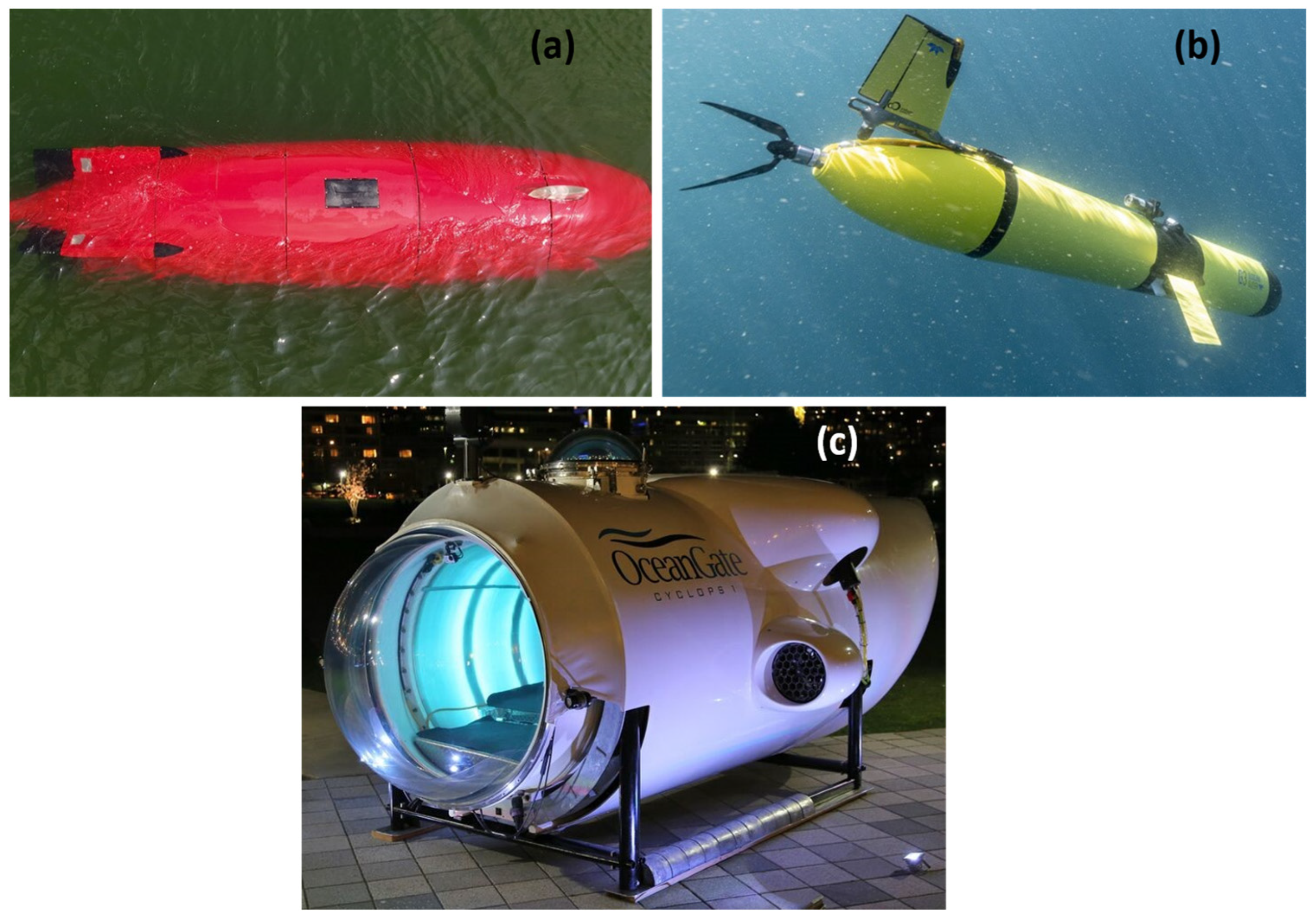
Figure 1. Composite pressure vessels: (a) DIVE-LC AUV, (b) Slocum underwater glider, and (c) Cyclops I HOV.
Jmse 12 01468 g001
Figure 2. Illustrations of buckling and material failure–initiated implosions.
Jmse 12 01468 g002
Figure 4. Procedure for obtaining the failure pressure of a thick isotropic cylinder.
Jmse 12 01468 g004
Figure 5. Water temperature variation with an increase in depth for tropical, mid-latitude, and polar regions.
Jmse 12 01468 g005
Figure 6. Composite manufacturing processes: (a) filament winding; (b) roll wrapping.
Jmse 12 01468 g006
Figure 7. Titan imposable design sketch.
Jmse 12 01468 g007
Figure 8. Optimized layup scheme for a 5-ply carbon fiber–based implodable.
Jmse 12 01468 g008
Table 1. Material properties of the Titan submersible’s hull.
MaterialTensile Modulus (GPa)Tensile Strength (MPa)Density (g/cm3)Elongation (%)Filament Diameter (µm)
Grafil 37-800 carbon fiber25555201.812.166
Epon resin 862 + Lindride LS-81K curing agent2.7373.771.165-
Table 2. Estimated elastic properties for the Titan submersible at a 60% fiber volume fraction.
PropertiesValues
E11 (GPa)154
E22 (GPa)8.85
v120.32
G12 (GPa)3
A (N/m) 1.039 0.036 0   0.036 1.039 0   0 0 0.039 × 10 10
B (N) 1.225 0 0   0 1.225 0   0 0 0 × 10 6
D (N m) 1.396 0.049 0   0.049 1.396 0   0 0 0.052 × 10 7
Disclaimer/Publisher’s Note: The statements, opinions and data contained in all publications are solely those of the individual author(s) and contributor(s) and not of MDPI and/or the editor(s). MDPI and/or the editor(s) disclaim responsibility for any injury to people or property resulting from any ideas, methods, instructions or products referred to in the content.