Abstract
In this study, a two-phase flow numerical wave tank model based on the viscous flow theory was applied to conduct computational research on the interaction between waves and submerged horizontal cylinders. The research objective is to reveal the hydrodynamic characteristics of nonlinear loads on submerged horizontal cylinders with a focus on vortex effects. The influence of the sharp and round corners of cross-sections on the wave forces on cylinders was summarized. The reasons for the characteristics of the wave forces were explained by analyzing the flow field distribution around the cylinder and decomposing the wave forces into inertial and drag forces. This study found that under the various incident wave amplitudes, the section corner and aspect ratio have significant impacts on each frequency component of the horizontal and vertical wave forces. The distribution of the vorticity field shows that the vortex effects lead to the differences between the loads on the cylinder under different cross-sectional corners and aspect ratios. The characteristics of inertial forces and drag forces on the cylinders were given by comparing and analyzing the cases with different sectional sharp and round corners. The inertia and drag coefficients were obtained by solving Morison’s equation. Under various Kc and Re numbers, the maximum values of the inertia and drag coefficients obtained are significantly different from those for submerged cylinders under oscillatory flow action.
1. Introduction
The hydrodynamic characteristics of ocean engineering structures, such as offshore oil–gas pipelines and submerged floating tunnels, under wave action are widely concerned in the research field of ocean engineering hydrodynamics. The main part of the above-mentioned structures is often simplified as a submerged horizontal circular cylinder, and the mechanical characteristics of the structures under wave action have been widely studied.
Early studies on the interaction between waves and submerged horizontal cylindrical structures were mainly carried out on the basis of experimental investigations. Chaplin [1] first conducted experimental research on wave forces on a submerged horizontal circular cylinder. The experimental data and the potential flow results were compared, and a significant difference between the two sets of results was found. Wang et al. [2,3] carried out a series of experimental studies on the interaction between an oblique incident solitary wave and a horizontal cylinder and observed that the vortices formed behind the cylinder had a significant impact on the vertical forces.
With the rapid development of computer technology, a number of numerical investigations on the interaction between waves and submerged horizontal cylinders have been carried out. The potential flow theory has been applied in related research due to its fast solving speed. Feng et al. [4] analyzed the characteristics of high harmonics in the focus wave group by using a nonlinear potential flow model. The high harmonic wave-height coefficients for wave groups with different steepness were calculated, and the nonlinear focus wave group was reconstructed with the obtained wave-height coefficients. Subsequently, Feng et al. [5] studied the characteristics of high harmonic wave forces on cylinders under extreme wave action. By comparing the experimental data with the results obtained from a fully nonlinear potential flow model, it was found that there were differences in the third harmonic component of the forces, while the other harmonic components were in good agreement. With the attention paid to the viscosity of fluid and rotation in flow, related studies have been carried out based on the viscous flow theory successively. Hu et al. [6] constructed a viscous flow numerical method to study the effects of a partially submerged cylinder on wave-height attenuation under different conditions of submerged volume and proposed a semi-analytical method to study this issue. Referring to Chaplin’s [1] experimental setup, Tavassoli and Kim [7] established a two-dimensional numerical wave tank model based on the viscous flow theory by using a mixed finite difference and finite volume method. The wave forces on a submerged horizontal circular cylinder were calculated under a lower Reynolds number (Re) and were significantly larger than the experimental data. Teng et al. [8] used a viscous flow model to calculate the forces on a horizontal submerged cylinder under nonlinear wave action. The study focused on the difference between the viscous flow results and potential flow results and explained the reason by analyzing the characteristics of the flow field around the cylinder. Gu et al. [9] simulated the characteristics of multi-scale vortices in a cylindrical wake at Re = 9500 based on the viscous flow theory and found that cavitation causes vortices to adhere to the surface of the cylinder, thereby suppressing vortex shedding. By using a two-dimensional viscous flow numerical model, Zhou et al. [10,11] studied an oscillating horizontal circular cylinder under wave and current action. The study found that the motion response of the semi-submerged cylinder is greatly affected by the flow, and the vertical vibration amplitude of the cylinder is relatively small; the motion of the quarter-submerged cylinder is mainly affected by the waves, and the vertical vibration amplitude of the cylinder is relatively large. These conclusions are helpful to better understand the dynamic response of horizontal floating cylinders under the combined action of wave and current, and have important guiding significance for the design and safety of offshore engineering structures. Ding et al. [12] established a viscous flow numerical model and studied the interaction between internal solitary waves and a series of double cylinders. The study found that the vortex distribution and vorticity intensity around the cylinder are susceptible to the vertical position of the cylinder and the distance between the two cylinders. In order to avoid the horizontal fluid loads on submerged structures, a flat cross-sectional form is often adopted for the main structure and supporting structure of immersed tube tunnels, submerged floating tunnels, and sea-crossing bridges in engineering.
The studies on the interaction between waves and horizontal submerged cylinders with various cross-sectional shapes and aspect ratios have recently received widespread attention. Selvan et al. [13] established a numerical model based on the potential flow theory to study the hydrodynamics issues when linear waves interact with multiple net cages, focusing on the wave scattering phenomenon during the interaction between waves and net cages. The study found that the porous structure characteristic of the net cages leads to wave energy dissipation, thereby reducing the wave amplitude that passes through the net cages; due to wave scattering and energy dissipation, the wave amplitude when interacting with multiple net cages is smaller than when interacting with a single net cage. Kushwaha et al. [14] conducted research on the hydrodynamics of the interaction between linear waves and vertical cylinders based on the potential flow theory. The study found that as the length of the cylinder increases, the horizontal force on the cylinder decreases, while the vertical force increases; both the horizontal and vertical forces on the cylinder decrease with the increase in the cylinder’s radius; after the wave passes through the structure, energy dissipation occurs, leading to the gradual disappearance of the wave after it passes through the structure. Yang et al. [15] experimentally studied the wave forces on a horizontal elliptical cross-sectional cylinder and examined the effects of incident wave period, amplitude, and direction on the wave forces. It was found that wave forces have a strong correlation with the incident wave period and direction. The experimental results provide important data and insights into the wave force estimation of large elliptic columns under extreme wave events and have guiding significance for the design of offshore engineering structures. Venugopal et al. [16] considered the conditions of small Keulegan Carpenter number (Kc) and studied the effects of sectional aspect ratio on the wave forces and hydrodynamic coefficients of rectangular cylinders. The study showed the inertia and drag coefficients decrease with an increase in Kc. A large amount of theoretical analysis and numerical studies has been conducted on the interaction between waves and cylinders with various sectional shapes. The experimental results can be used to predict and study resonance phenomena and to design new coastal protection structures. Liu et al. [17] developed an analytical method based on the potential flow and linear wave theories. With the curvature radius function of the cross-section profile obtained from the Fourier series, the model can be used to study the interaction between linear waves and smooth profile cross-section cylinders. Based on the potential flow theory, the proposed analysis method can accurately predict wave force and wave upthrust, and the estimation of wave force in engineering design is simple and accurate. Liu et al. [18] proposed an identification method for predicting wave force on structures by combining experimental data and mathematical modeling. The accuracy of this method in predicting wave forces on a partially submerged elliptical cross-section cylinder was verified by comparing the numerical results with the experimental data. Han et al. [19] studied the characteristics of wave forces on a partially submerged elliptical cylinder undergoing free oscillation by using a semi-analytical method based on the potential flow theory, and analyzed the relationship between the natural frequency, cross-sectional size, fluid density, submergence depth of the cylinder, and the dimensionless frequency parameters. Chatjigeorgiou et al. [20,21] proposed an analytical method based on the potential flow theory for the diffraction problem of wave action on a cylindrical array with an elliptical section, and provided analytical solutions for the wave forces on the cylinders. Ai et al. [22] established a numerical model based on the viscous flow theory, studied the problem of nonlinear wave action on a horizontal rectangular cylinder, and analyzed the distribution characteristics of vorticity and velocity fields around the cylinder. The study found that the vorticity distribution is complex and the duration of vortices is quite long, which leads to the changes in the pressure field and affects the stability and bearing capacity of the structure. With a numerical model based on the viscous flow theory, Chen et al. [23] studied the interaction between internal solitary waves and circular and elliptical cross-section floating structures, and investigated the effects of submerged depth and incident wave amplitude on the wave forces and the structural motion response. It was found that compared to the case of a circular cross-section, the elliptical section structure exhibits smaller heave, sway, and roll motions. Ding et al. [24] conducted numerical simulations on the interaction between internal solitary waves and a submerged rectangular cross-section cylinder based on the viscous flow theory in a three-dimensional space. The study found that the horizontal wave forces on the cylinder showed a trend of first increasing and then decreasing with the increase in section width, and the shedding form of the vortices around the cylinder changed significantly as the wave incidence angle changed.
The above-related research lacks a systematic comparison and analysis of wave forces on horizontally submerged cylinders with various cross-sectional corners and aspect ratios; that is, as typical influence factors, the influences of cross-sectional shape on wave forces on submerged cylinders have not been induced and summarized. This study applies the wave generation model ‘waves2Foam’ based on the open-source platform ‘OpenFOAM’ [25] to establish a viscous flow numerical wave tank model by developing fluid motion calculations. The present research is conducted on the influence of cross-sectional shape on the wave forces on submerged horizontal cylinders. The important factors, such as incident wave amplitude, section corner, and aspect ratio of the cylinder, are investigated in the numerical calculations. Under the effects of the above important factors, the characteristics of various harmonic wave forces on the cylinders are analyzed and summarized. The causes of the physical phenomena are explained through an analysis of local flow field characteristics and the decomposition of wave forces on the cylinders. The hydrodynamic coefficients are calculated based on Morison’s equation and the numerical results.
2. Mathematical Model
This study applies the wave generation model ‘waves2Foam’ based on the open-source platform ‘OpenFOAM’ to develop the fluid motion calculations.
For incompressible viscous flow problems, the Navier–Stokes equation composed of continuity equation and momentum conservation equation can be expressed as follows:
where ui and uj are the velocity components of fluid quality points in the i and j directions; ρ is the fluid density; t is the time; μ is the dynamic viscosity; p is the fluid pressure; and gi is the gravitational acceleration.
The numerical discretization process of the finite volume method includes spatial discretization and temporal discretization. The principle of spatial discretization is to define the computational domain through a series of points, filling the entire bounded computational space. The entire computational space is discretized into multiple grid elements, and then partial differential equations are discretized based on this. The spatial discretization of the finite volume method involves dividing the entire computational domain into continuous and non-overlapping finite element volumes. Due to categorizing the interaction between waves and structures as a transient problem, the time term is discretized. We define any tensor operator as B, and the spatial term can be represented as Bϕ, where ϕ is the surface flux. The integral form of the partial differential equation can be expressed as follows:
According to Euler’s implicit form, the terms in the above equation can be expressed as follows:
where B* is the discrete form of B.
The VOF method is used to capture the complex morphology of free surfaces efficiently [26,27]. The fluid density and viscosity in the computational cells can be computed as follows:
where α is the volume fraction, and the subscripts ‘g’ and ‘l’ represent the air phase and liquid phase. For the air phase, α = 0; for the liquid phase, α = 1; and for the interface, α is between 0 and 1.
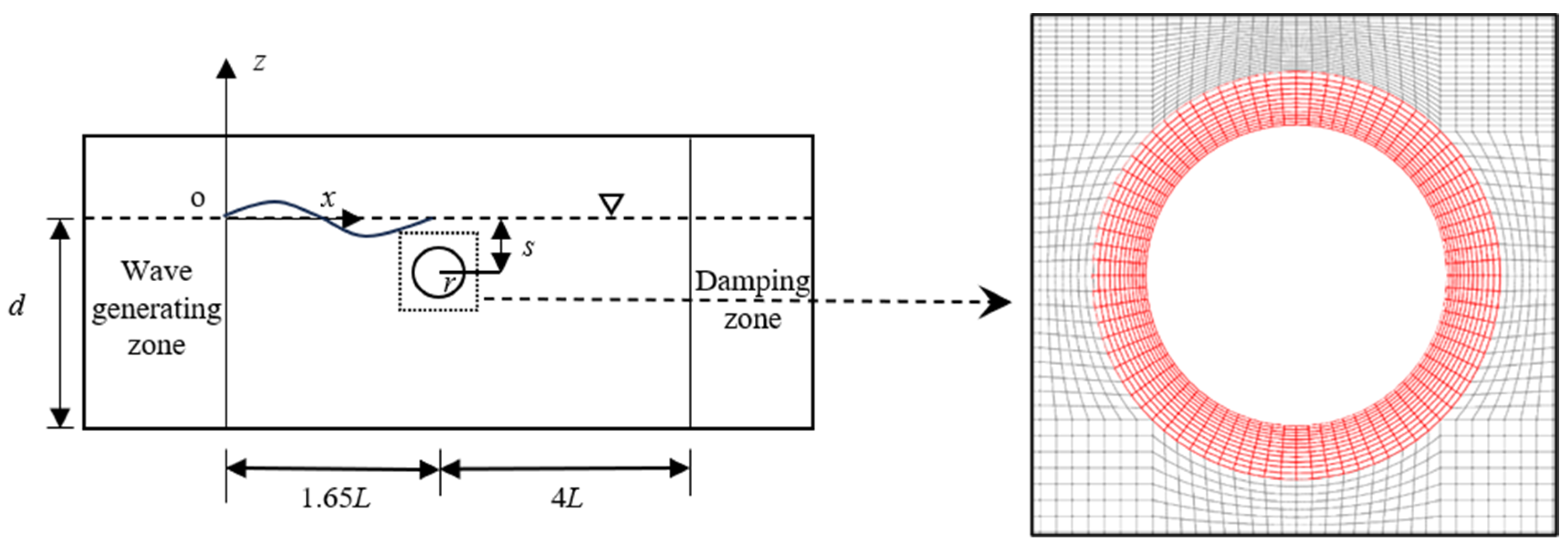
Figure 1 shows the numerical wave tank model and its boundaries. The velocity components of the wave field are specified at the wave generation boundary ‘AB’, and the pressure condition is ∂p*/∂n = 0 (p* = p − ρgh is the dynamic pressure, where h is the distance from a point to the still-water level). ‘CD’ and ‘BD’ are the wave-damping boundary and bottom boundary, respectively, with the same velocity and pressure conditions of ui = 0, ∂p*/∂n = 0; ‘AC’ is the top boundary; and the velocity and pressure conditions are ∂ui/∂n = 0, p* = 0.
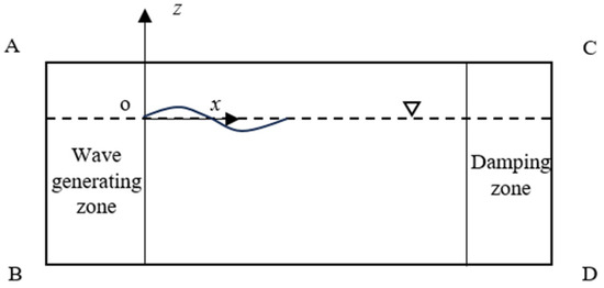
Figure 1.
Sketch of numerical wave tank boundaries.
The wave generation speed boundary is based on the fifth-order Stokes wave theory to generate nonlinear waves. According to the analytical form of the fifth-order Stokes theory proposed by Fenton [28], the fluid quality point velocity equation is as follows:
where ux and uz are the velocity of fluid quality points in the x and z direction, k is the wave number, d is the water depth, and c is the wave speed. ω is the angular frequency, and z is the distance from the fluid quality point to the still water surface.
3. Numerical Verification
3.1. Grid Convergence Verification
To verify the correctness of the numerical wave tank model, a convergence examination for the computational grid was carried out. The sketch of the verification calculations is shown in Figure 2. Referring to Chaplin’s experimental research [1], in this verification, the submergence depth of the circular cylinder is s = 0.102 m, and the cylinder radius is r = 0.051 m. The incident waves are generated based on the fifth-order Stokes wave theory, the wave period is T = 1.0 s, and the water depth is d = 0.85 m. The cylinder is 1.65 L away from the wave-making zone (L is the wavelength) and 4.00 L away from the wave-absorbing zone. Four sets of meshes with different resolutions were utilized for the verification calculations. The radius of the refinement area around the circular cylinder is ra = 0.03 m, as shown in Figure 2.
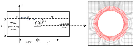
Figure 2.
Sketch of wave action on a submerged horizontal circular cylinder and the typical grid of the refinement area for the simulations.
The mesh parameters and corresponding cell number are listed in Table 1. There are different numbers of cells for the meshes M1, M2, M3, and M4 in a wavelength, in a wave height, along the cylinder surface, and in the radial direction of the refinement area.

Table 1.
Mesh parameters and cell number.
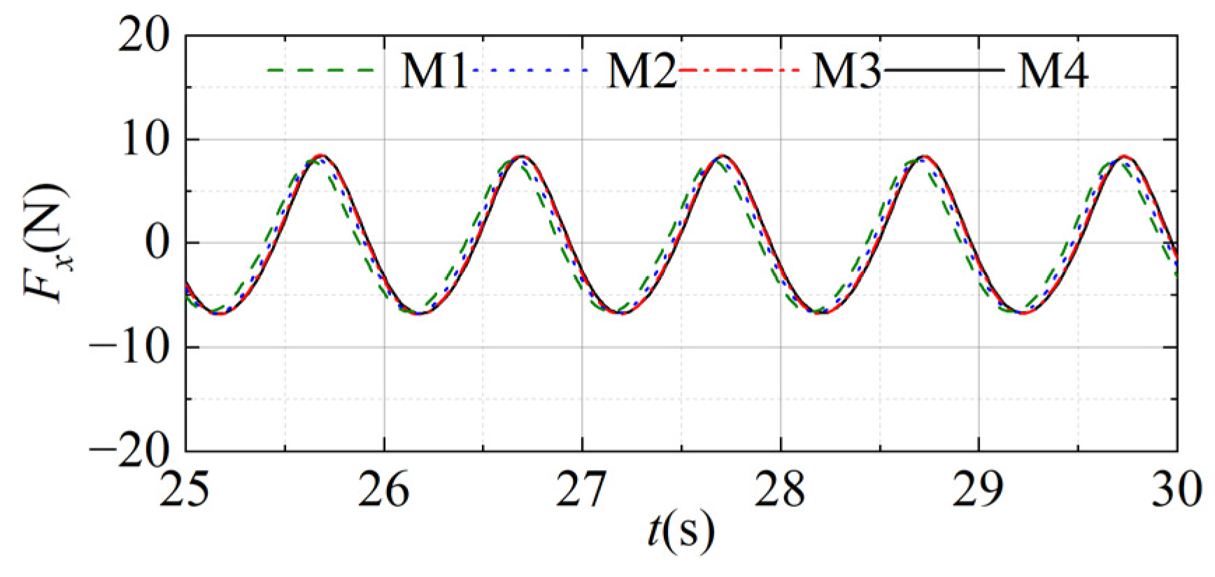
The case with A/r = 0.36 is chosen as an example, where A/r is the dimensionless form of the wave amplitude. The time series of the horizontal wave forces on the circular cylinder under different mesh resolutions are shown in Figure 3. It can be seen that the force results of Mesh 3 and Mesh 4 are convergent. The results of Mesh 1 and Mesh 2 deviated from those of Mesh 3 and Mesh 4 and failed to meet the accuracy requirements. To improve computational efficiency, the grid settings of Mesh 3 will be adopted in the following numerical study.
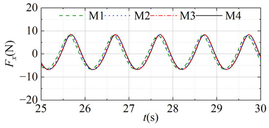
Figure 3.
Time series of the horizontal wave forces under different mesh resolutions.
3.2. Verification of Wave Force Calculation
To verify the accuracy of the numerical model in calculating the wave forces on submerged structures near the free surface, the issue of wave action on a submerged horizontal circular cylinder is investigated again. The calculation settings and parameters of the experimental study by [1] are referenced. The incident wave amplitudes are selected as A/r = 0.12, 0.24, 0.36, 0.48, and 0.60. The wave forces on the circular cylinder are calculated by:
where and represent the pressure force and viscous shear force, respectively; is the unit normal vector, is the unit tangential vector; is the shear force, where is the tangential velocity.
To examine the amplitude, mean value, and high harmonic components of wave force, the Fast Fourier Transformation [29] method is commonly used in mathematical methods to convert the wave force from the time domain to the frequency domain. To obtain the wave forces at various harmonics, the forces on structures can be expanded into a Fourier series as follows:
where F(0) and F(n) are the mean force and the n-th harmonic force, respectively; φ(n) is the phase of the n-th harmonic component.
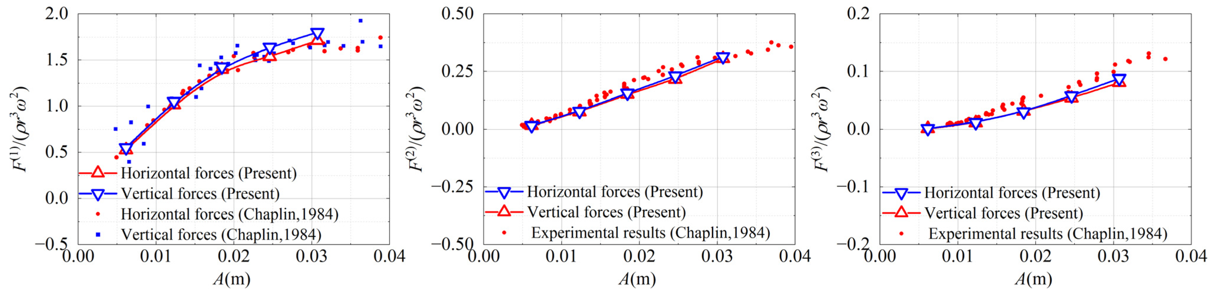
The present numerical results of the first, second and third harmonic wave forces on the horizontal circular cylinder as functions of A are compared with the data from the experiments of Chaplin [1], as shown in Figure 4. In the figure, ‘F/(ρr3ω2)’ is the dimensionless form of wave force. The present numerical results are in good agreement with the previous experimental data. This shows that the present numerical model has good accuracy in calculating the wave forces on submerged horizontal cylinders.
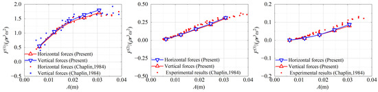
Figure 4.
Wave forces on the circular cylinder as functions of A [1].
4. Wave Force on Cylinders with Various Section Corners and Aspect Ratios
4.1. Calculation Settings and Parameters
The present simulations of wave action on submerged horizontal cylinders with different section corners and aspect ratios are set up by using the proven numerical model. The wave forces on the cylinders with the various section shapes and aspect ratios are investigated, and the influences of the important factors on the force characteristics are described in detail.
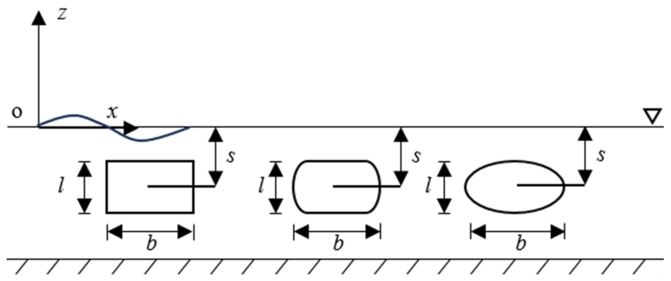
The cross-sectional corners of the cylinders considered for the calculations include sharp corners, semi-round corners, and round corners. The typical cross-sectional shapes of the cylinders, correspondent of the sectional corners, are rectangular, curved rectangular, and elliptical. Figure 5 shows the section shapes and related parameters. The characteristic size of the cylinders is the length of the two-dimensional long side, and it is set as D = b = 0.102 m. The characteristic size D is consistent in all the cases. For the two-dimensional simulations, the characteristic size is the projected area of the cylinders in the horizontal direction. The change in the aspect ratio of the cross-section is achieved by adjusting the height l. b/l = 1.0, 1.2, 1.4, 1.6, 1.8, and 2.0 are considered for the various aspect ratios (b/l is the dimensionless form of aspect ratio).
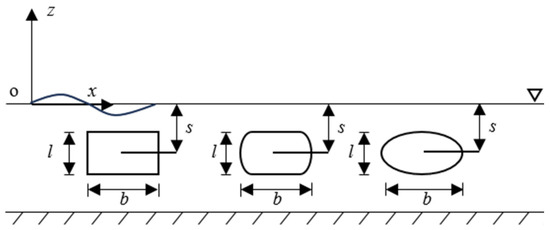
Figure 5.
Sketch of cylinders and sizes. (b—length of cylinder, s—submerged depth of the cylinder, and l—height of cylinder).
The computational domain and the position of the cylinders are the same as shown in Figure 2. The submerged depth of the cylinders is s = 0.102 m, and the water depth is d = 0.85 m. The cylinders are 1.65 L and 4.00 L away from the wave-making zone and the wave-absorbing zone, respectively. The incident wave is generated based on the fifth-order Stokes wave theory. A/D = 0.060, 0.120, 0.180, 0.245, and 0.285 are selected as the dimensionless wave amplitudes for the simulations.
4.2. Wave Force Results
The influence of section shape on the first and higher harmonic nonlinear loads on the cylinders is investigated. Under various incident wave amplitudes, the harmonic components of the horizontal and vertical wave forces are obtained following Equation (9). To analyze the characteristics of wave forces on the cylinders, the dimensionless wave forces are represented as ‘F/(ρgDA)’.
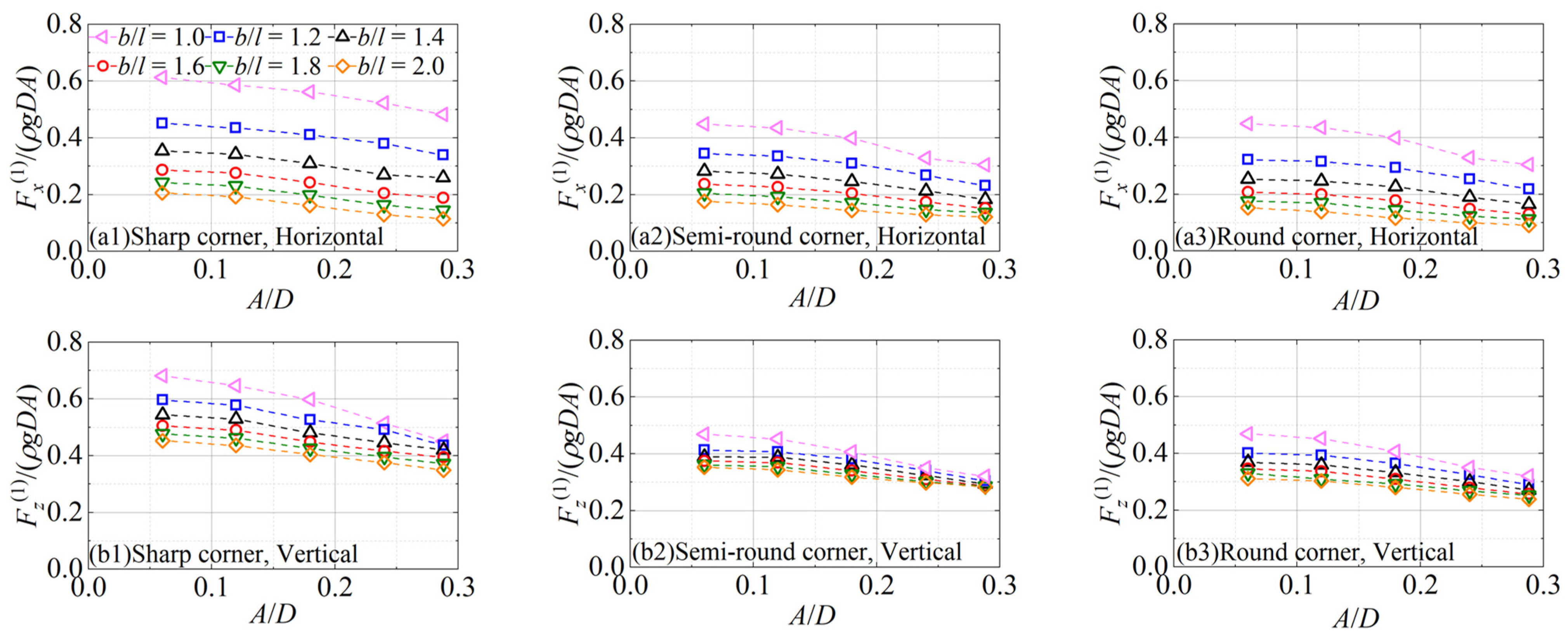
To examine the effects of aspect ratio and wave amplitude on the wave forces, the comparisons of the first harmonic wave forces on different section cylinders are shown as functions of the wave amplitude in Figure 6. For the three section corners considered in the simulations, the first harmonic forces are larger at the smaller b/l. The dimensionless horizontal and vertical forces show a similar trend under all b/l; that is, they decrease with the increase in A/D. The vertical forces are always larger than the horizontal forces, and with the increase in b/l, the differences increase gradually.
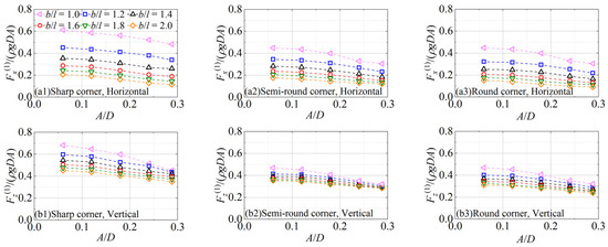
Figure 6.
The first harmonic wave forces on the cylinders at different b/l as functions of A/D.
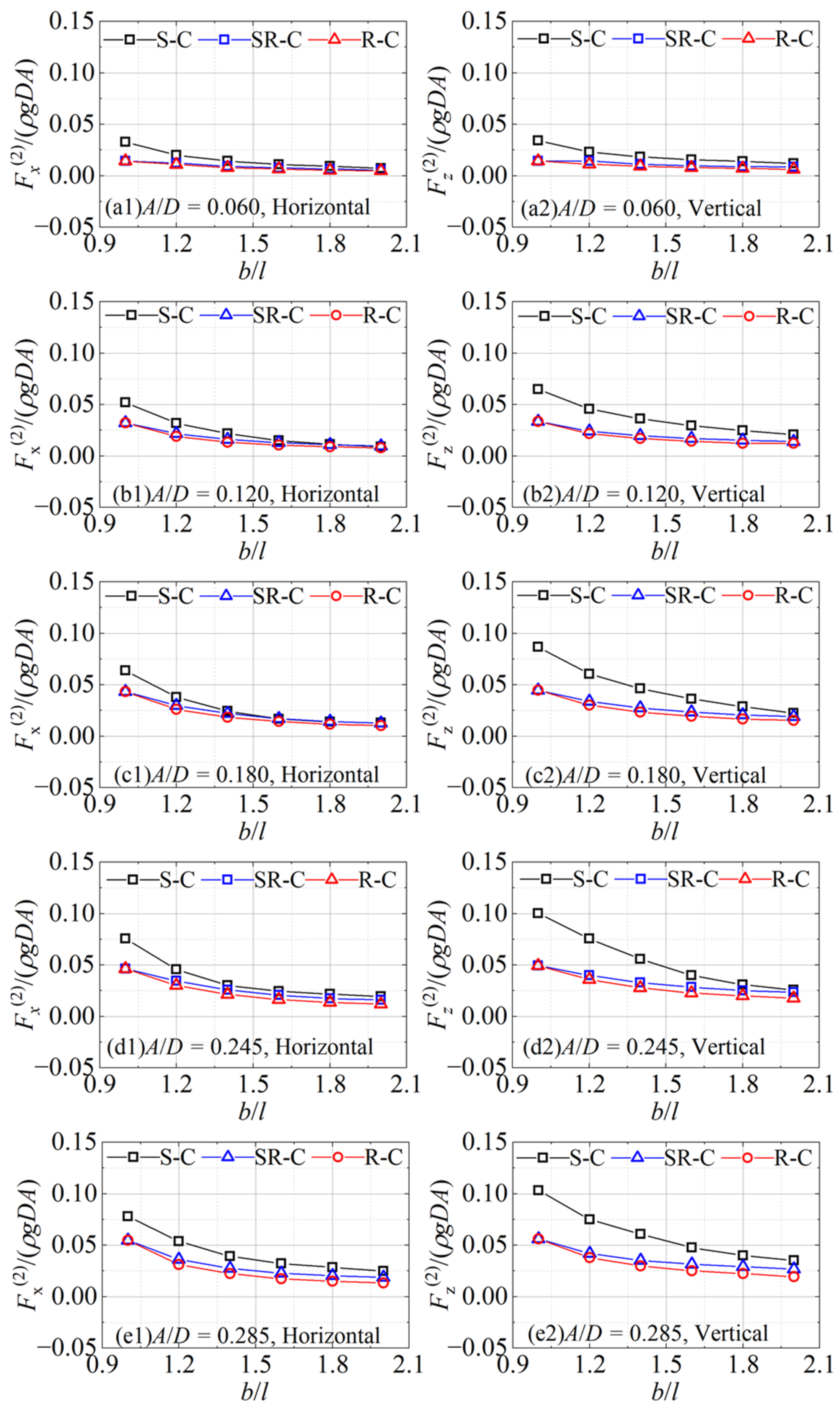
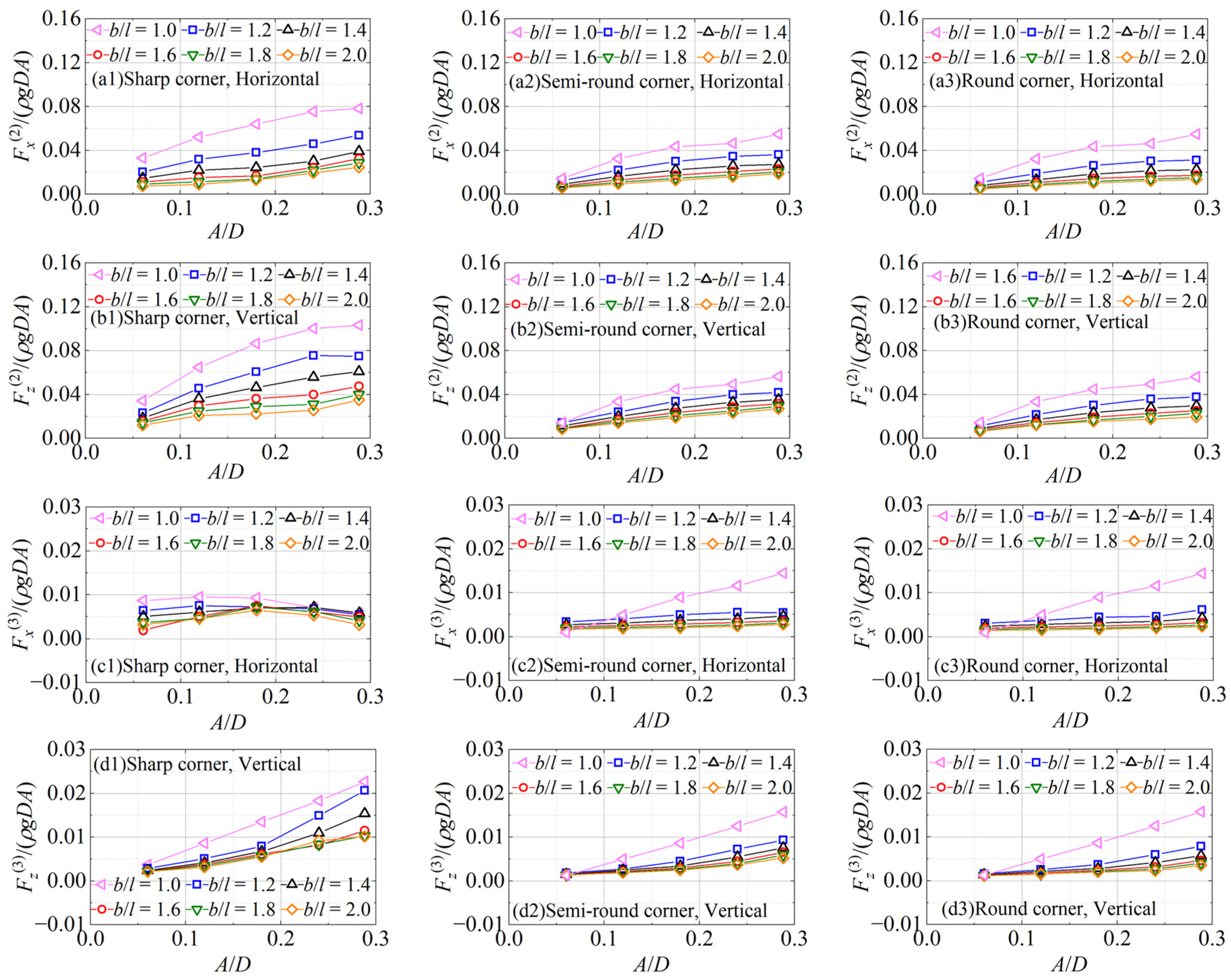
The second harmonic wave forces on the cylinders under different cross-sectional corners as functions of the aspect ratio are shown in Figure 7. In the legends, ‘S-C’, ‘SR-C’, and ‘R-C’ represent the cases with the sharp corner, semi-round corner, and round corner of the cylinder sections, respectively. It can be seen that the second harmonic horizontal and vertical forces on the cylinder with semi-round corners are close to those on the round-corner cylinder, and smaller than the forces on the sharp-corner cylinder. As b/l increases, the differences between the second harmonic forces on cylinders with different sections gradually narrow. It indicates that the nonlinear effects are significant in the second harmonic forces, especially in the cases of sharp-corner sections, and this effect becomes greater when the b/l is smaller. Unlike the characteristics of the wave forces on a circular cylinder, for the second harmonic component, the horizontal forces are no longer close to the vertical forces; that is, the vertical forces are greater than the horizontal forces under the sectional conditions of the sharp corner, semi-round corner, and round corner. The reason is although there is no change in the submerged volume and characteristic size of the cylinder, the projected area in the horizontal direction gradually decreases when the cross-sectional shape tends to be flat. The dimensionless second harmonic horizontal and vertical forces on the cylinders have a decreasing trend with the increase in b/l.
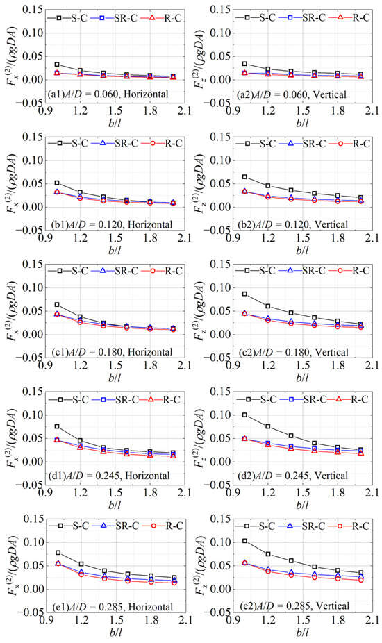
Figure 7.
The second harmonic wave forces on the cylinders under different section corners as functions of b/l.
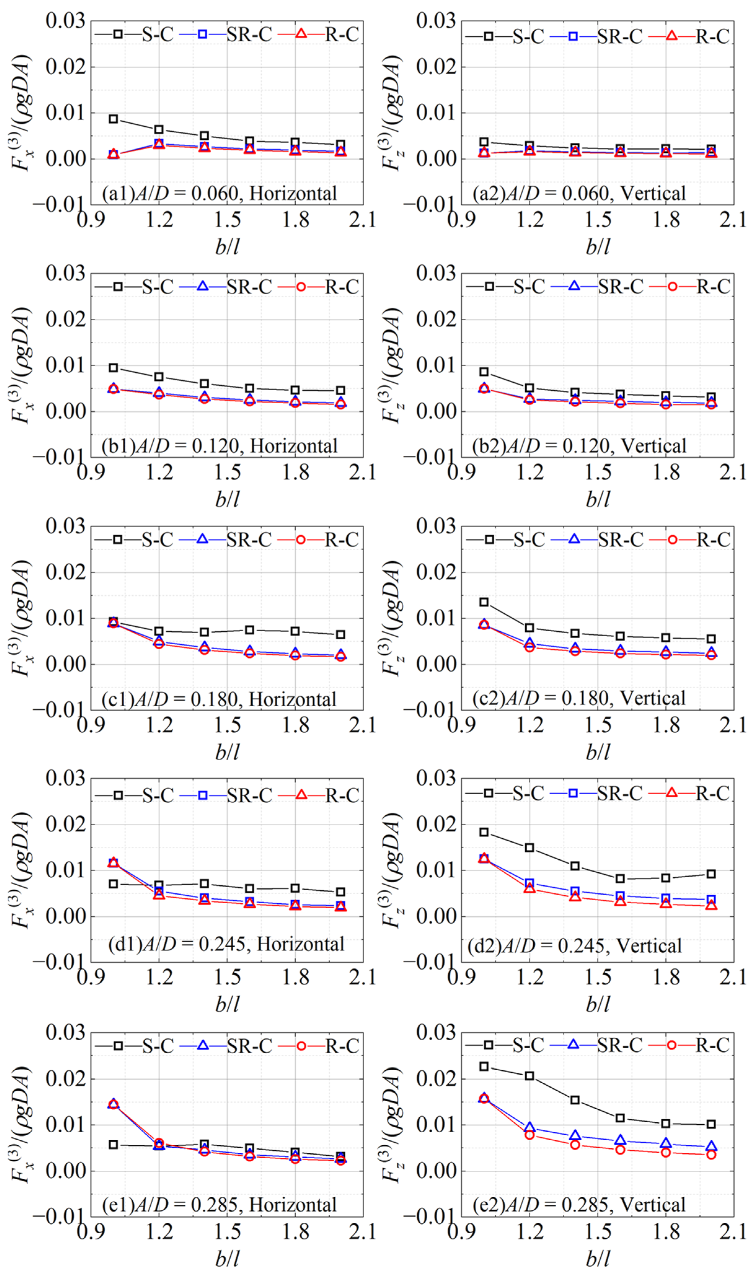
Figure 8 shows the third harmonic horizontal and vertical forces on the different section cylinders as functions of the aspect ratio. In general, the nonlinear loads are still the largest under the sharp-corner section in the vast majority of cases; the forces on the semi-round-corner and round-corner cylinders are close to each other. But, the third harmonic horizontal and vertical forces on the cylinders exhibit different characteristics to those of the first and second harmonic forces. Especially, the contrast relationship of the horizontal forces changes with the increase in wave amplitude (e.g., A/D = 0.180~0.85) at a small b/l (e.g., b/l = 1.0~1.2): the forces on the sharp-corner cylinder change from the largest to the smallest. For the third harmonic horizontal forces, the differences between the results under the sharp corner and the others increase at first, then decrease as b/l increases in general. However, the corresponding differences for the vertical forces gradually increase with the increase in b/l.
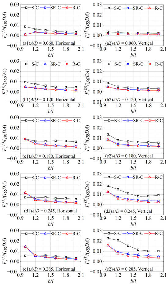
Figure 8.
The third harmonic wave forces on the different section cylinders as functions of b/l.
To compare the nonlinear effects of the aspect ratio, the higher loads on the different section cylinders are shown as functions of wave amplitude in Figure 9. For the smaller b/l, the stronger nonlinear effects are reflected, and the second and third harmonic horizontal and vertical forces are larger. Different from the first harmonic forces in the same dimensionless form, the higher harmonic components overall increase with the increase in A/D. There is a special nonlinear feature for the third harmonic horizontal forces as shown in Figure 9(c1), which is also embodied and described in Figure 8. In addition, it can be observed that under the same cross-section, the vertical forces are greater than the horizontal components.
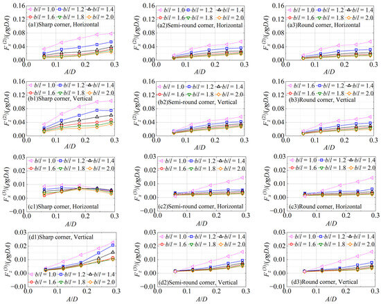
Figure 9.
The second and third harmonic wave forces on the cylinders at different b/l as functions of A/D.
5. Viscous Flow Field and Force Decomposition
5.1. Flow Field Distribution
To explain the characteristics of the various harmonic wave forces on the cylinders with sharp and round corners in Section 3, the pressure field, streamline distribution, and vorticity field around the cylinder are analyzed.
The vorticity field around the cylinders at the moments when the horizontal wave forces on the cylinders with different cross-sectional corners reach extreme values is shown in Figure 10. The cases at A/D = 0.285, with b/l = 1.2, are taken as examples. In the figures, ‘−tFxmax’ and ‘+tFxmax’ represent the moments when the horizontal wave forces reach the negative and positive extremes, respectively. Although the cylinders with different section corners have the same projection surface in the horizontal direction under the same characteristic size, as b/l increases, the cross-sections of the cylinders tend to flatten, and the vertical projection area gradually decreases. This causes the vertical forces to be larger than the horizontal forces for the first harmonic component on the sharp-corner, semi-round-corner, and round-corner cylinders. It is obvious that the disturbance of the free surface above the cylinders weakens with the increase in b/l, and this means the nonlinear effects of the free surface on the wave force decrease gradually. It is easy to understand that the nonlinear effects increase gradually with the increase in A/D in the second and third harmonic wave forces on the cylinders. The vorticity field shows that, by comparison, there are stronger vortices generated around the sharp-corner cylinder. This suggests that the corresponding higher harmonic forces show more remarkable nonlinear characteristics because of the stronger vortex effects.
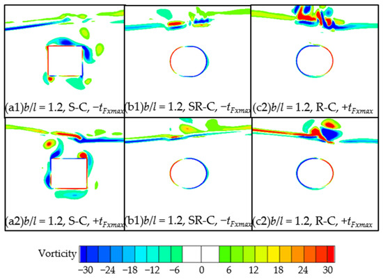
Figure 10.
Vorticity field (rad/s) around the cylinders when the horizontal forces reach extreme values.
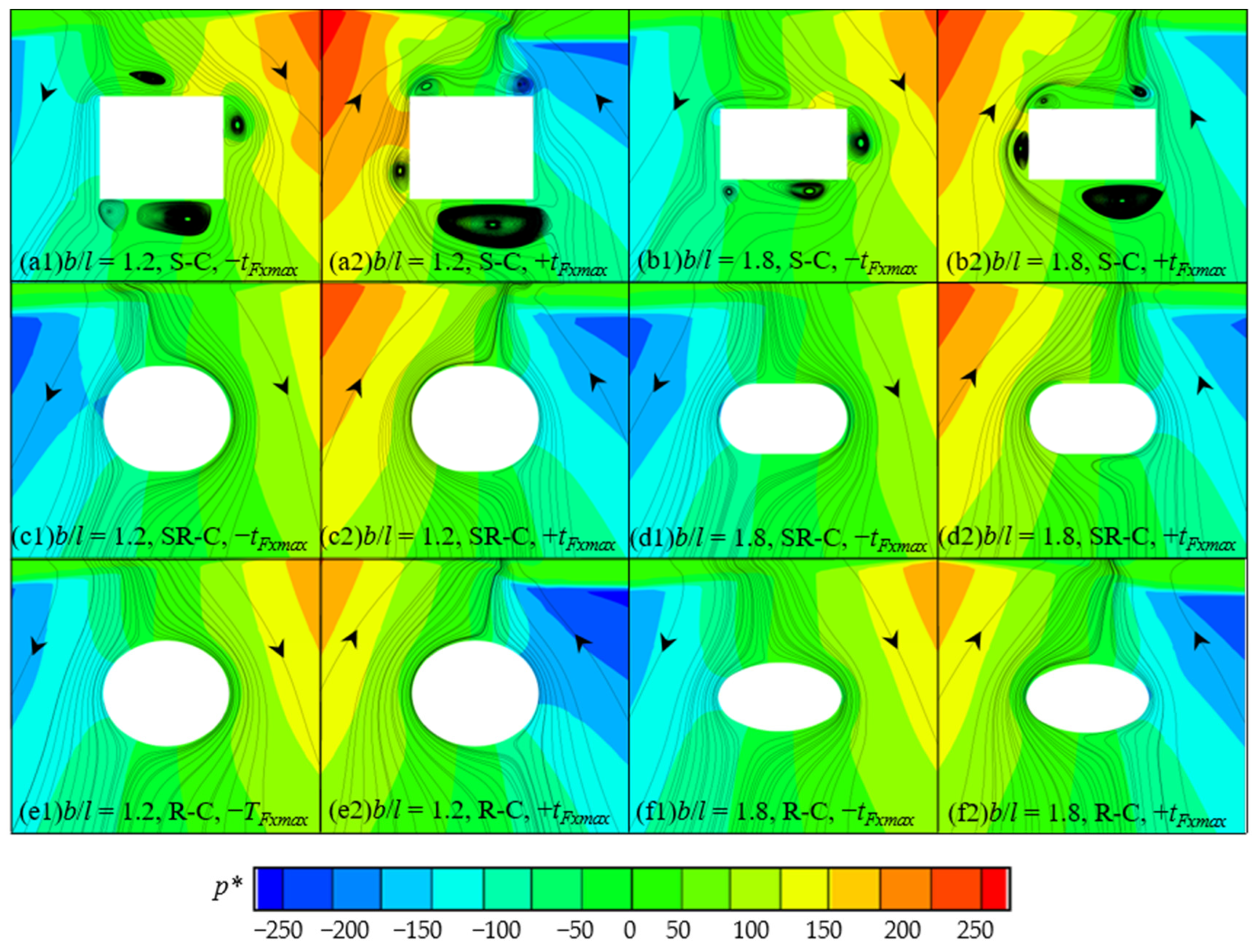
The dynamic pressure field and streamline distribution around the cylinders when the horizontal wave forces on cylinders with different cross-sectional corners reach extreme values for the cases of A/D = 0.285, and b/l = 1.2 and 1.8 are shown in Figure 11. It can be found that under the same aspect ratio and incident wave condition, the characteristics of the pressure field and streamline distribution around the semi-round-corner and round-corner cylinders are similar. As the aspect ratio gradually increases, due to the increasingly flattened cross-section shape, the influence of the semi-round-corner and round-corner cylinders on fluid flow and the motion of vortices around the cylinder gradually decreases, so the degree of flow field similarity gradually increases. However, the pressure and streamline distribution around the sharp-corner cylinder are significantly different from those around the semi-round-corner and round-corner sectional conditions. As shown in Figure 10, due to the relatively stronger vortices generated around the sharp-corner cylinder, the pressure distribution on the surface of the cylinder is affected by the vortices. This leads to the larger pressure forces on the sharp-corner cylinder. Therefore, the higher harmonic wave forces acting on the semi-round-corner and round-corner cylinders are relatively close to each other, and smaller than those on the sharp-corner cylinder. By observing the pressure field and streamline distribution around the cylinders, it can be found that with the increase in b/l, the similarity of the fluid field distributions under the different cross-sections gradually increases. Thus, the gaps between the dimensionless second harmonic wave forces on the different section cylinders are gradually narrowing. It indicates that as the cross-sectional shape of the cylinder tends to be flatter (b/l increases), the nonlinear effects decrease gradually on the higher harmonic wave forces on the cylinders, and the corresponding dimensionless forces decrease.
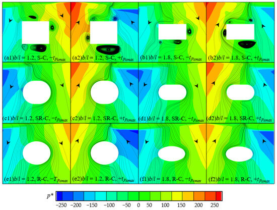
Figure 11.
Dynamic pressure (Pa) and streamline around the cylinders when the horizontal forces reach extreme values, where p* = p − ρgh is the dynamic pressure.
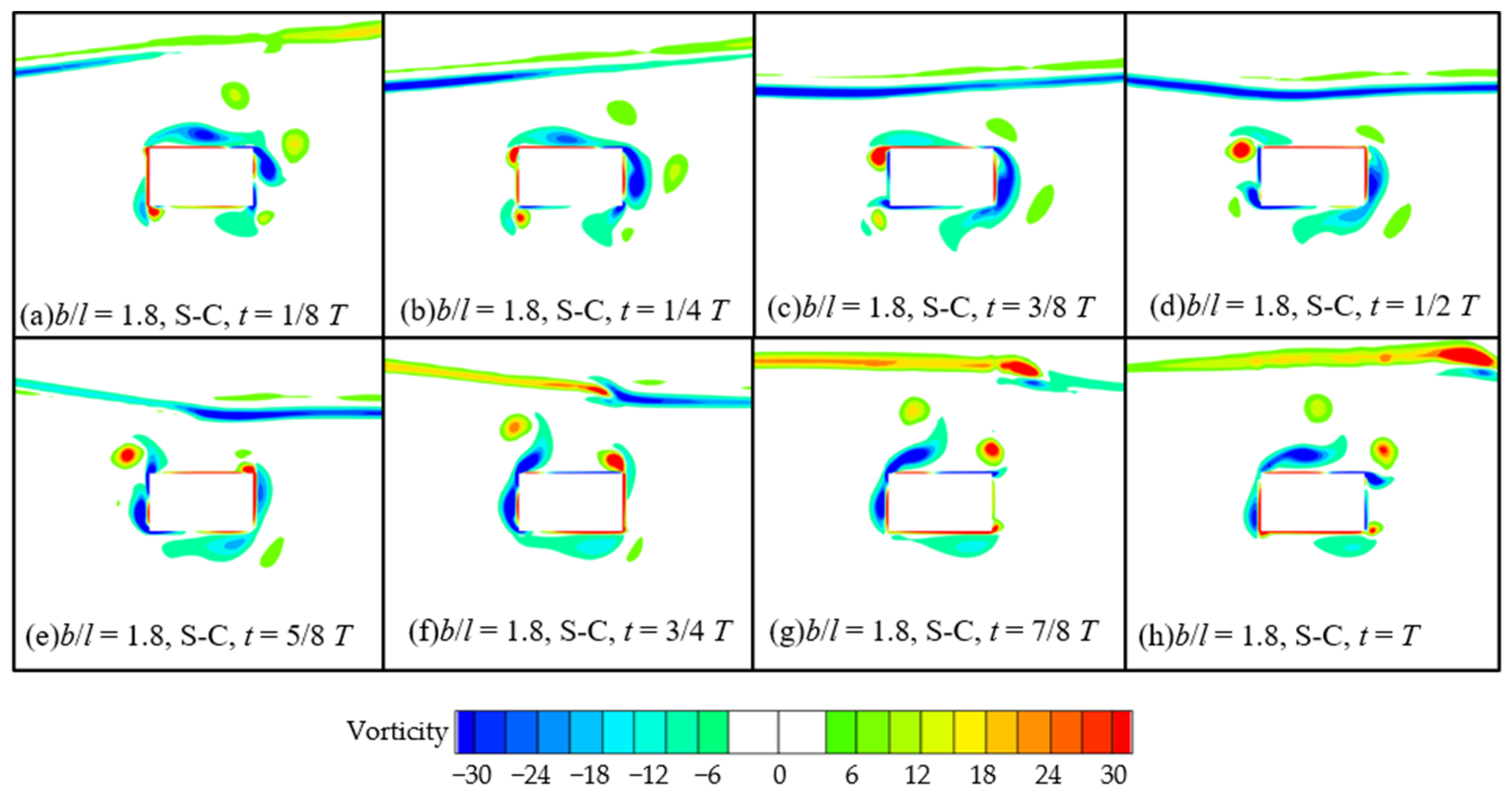
Considering the complexity of the vorticity field around the sharp-corner cylinder, The motions of the vortices around the cylinder at some instantaneous positions within a wave period are shown in Figure 12. The cases at A/D = 0.245 and b/l = 1.8 are taken as examples. The vortices are generated by the action of waves on the cylinder, and rotate clockwise around the cylinder with the motion of water particles in the wave field within a wave period. During the process of revolving around the cylinder, the vortices mostly adhere to the surface of the cylinder, and while gradually dissipating, they are also being generated synchronously. There is no significant phenomenon of periodic vortex shedding. Combining the vorticity field characteristics around the cylinders shown in Figure 12, the vortices around the sharp-corner cylinder under wave action are more significant and complex than those around the semi-round-corner and round-corner cylinders. It is necessary to further analyze the characteristics of the wave forces through force decomposition. For the small b/l, the height of the cylinder section is relatively large. In the process of the vortices around the sharp-corner cylinder, there are more extensive motion paths and longer time of vorticity dissipation and vortex formation on the side walls. This leads to the nonlinear effect of vortex motion on higher harmonic horizontal forces, which is different from the other cross-sectional cases. Thus, the special nonlinear characteristic of the third harmonic horizontal forces sharp-corner cylinder is observed at the small b/l as shown in Figure 8.

Figure 12.
Motions of the vortices (rad/s) around the cylinder.
5.2. Decomposition of Wave Force
To further analyze the force characteristics, the wave forces on the cylinders are decomposed into inertial forces and drag forces based on Morison’s equation [30], that is, in the phase of fluid flow acceleration and velocity in the wave field, as follows:
where F is the wave force; Fi is the inertial force; Fd is the drag force; Cm and Cd are the inertial and drag coefficients, respectively; V is the submerged volume; and S is the projection area of the structure, . In Equations (10) and (11), the subscripts x and z represent the components of physical quantities in the horizontal and vertical directions, respectively.
For the present issue of nonlinear wave action on submerged horizontal cylinders, the Kc and Re numbers can be expressed as follows:
where the kinematic viscosity coefficient is υ = μ × 10−3.
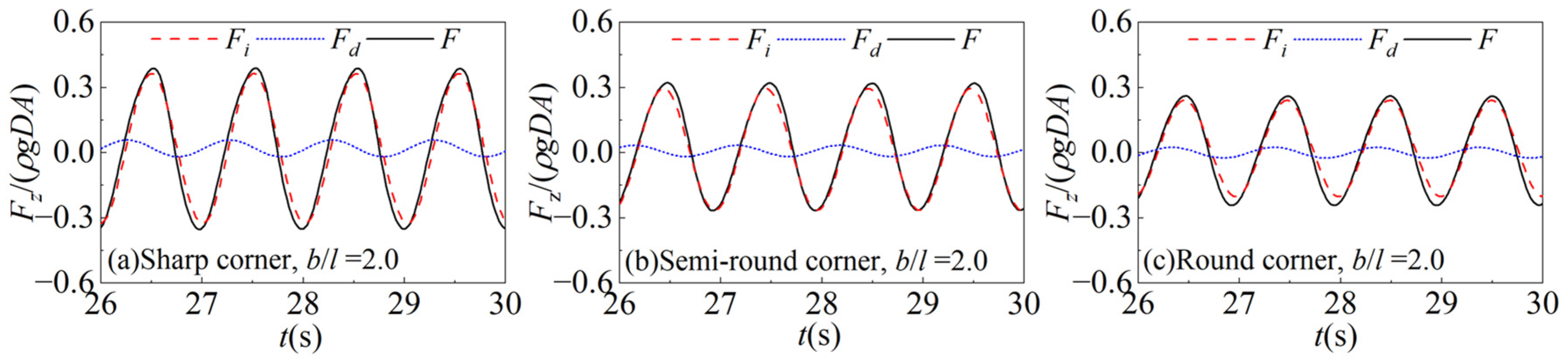
The vertical forces in the case of A/D = 0.245 and b/l = 2.0 are considered as examples. Figure 13 shows the time series of the total wave forces, inertial forces, and drag forces in the vertical directions. It can be seen that the inertial forces are close to the total wave force in terms of magnitude and phase. The contribution of the drag forces to the wave forces is small. The inertial forces can be determined as the dominant component of the wave forces on the cylinders.
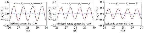
Figure 13.
Comparisons of the inertia forces, drag forces, and total wave forces.
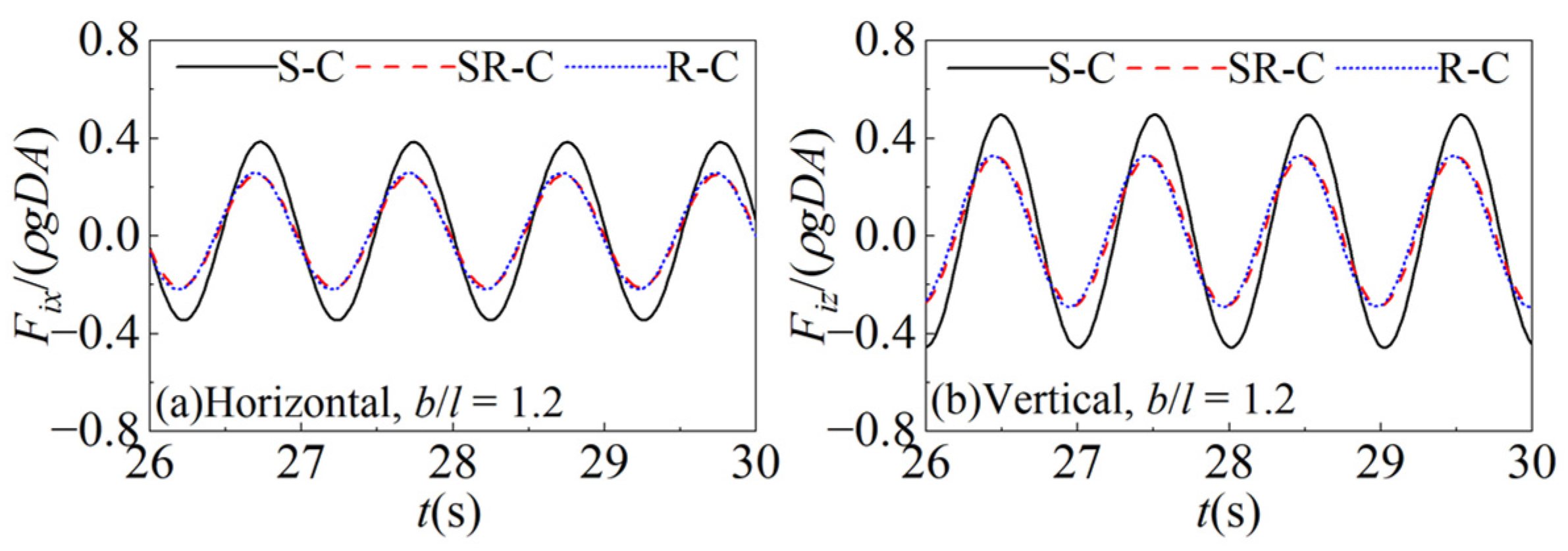
To further analyze and explain the characteristics of the wave forces, the inertial forces on the sharp-corner, semi-round-corner, and round-corner cylinders under the same aspect ratio are compared, and the time series of the inertial forces are shown in Figure 14. In the cases of A/D = 0.245 and b/l = 1.0, in both the horizontal and vertical directions, there are significant differences in the inertial forces acting on the cylinders with different section corners. The magnitudes and phases of the inertial forces on the semi-round-corner cylinder are relatively close to those on the round-corner cylinder. The inertial forces on the sharp-corner cylinder are the largest, and their phases, by contrast, are hysteretic.
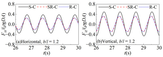
Figure 14.
Time series of the inertial forces on the cylinders with the different cross-sections.
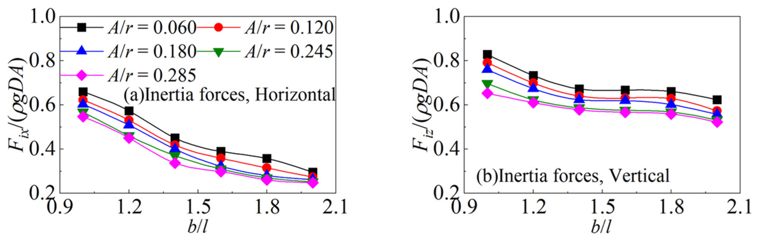
To determine the magnitude relationship of the inertial forces on the cylinders more clearly, the three cylinders with sharp and round corners at A/D = 0.245 under various b/l are considered for comparison. The comparisons of the inertial forces on the cylinders under various aspect ratios at the same wave amplitude are shown in Figure 15. The differences between the inertial forces on the different section cylinders decrease as b/l increases. The reason is that the sharp-corner cylinder has the largest volume under the same aspect ratio, and the round-corner cylinder has the smallest volume under the three different section corners. To a certain extent, this determines the magnitude of the inertial force. It can also be seen from Figure 11 and Figure 12 that the phase hysteresis phenomenon for the inertial forces in the cases of the sharp-corner cylinder is caused by a relatively strong vortex effect.
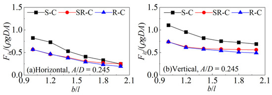
Figure 15.
Comparisons of the inertial forces on the cylinder with various aspect ratios.
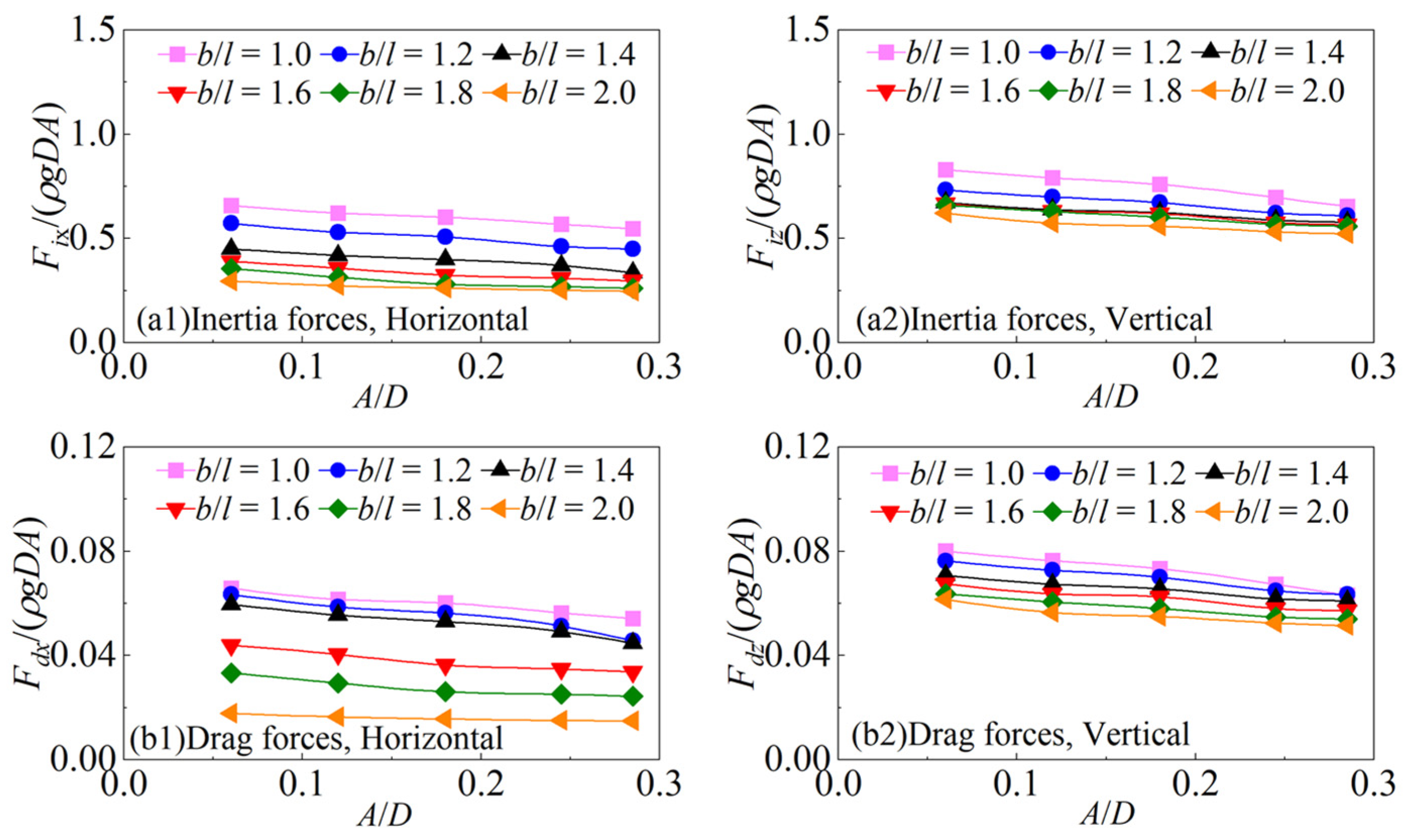
Taking the cases of the semi-round-corner cylinder at A/D = 0.245 under various b/l as examples, the comparisons of the inertial and drag forces on the cylinder with different aspect ratios under the same wave amplitude are shown in Figure 16. With the increase in b/l, the projection area of the cylinder in the vertical direction decreases, which leads to the decrease in the drag forces in the horizontal direction. However, due to the projection area in the horizontal direction remaining unchanged, there is no significant change in the vertical drag forces. In either the horizontal or vertical direction, the inertial forces are smaller with the larger b/l. That is because the submerged volume of the cylinder decreases with the increase in b/l. Therefore, for the first harmonic wave forces on the cylinders with various cross-sectional corners, with the increase in b/l, the dimensionless horizontal and vertical forces gradually decrease. From the numerical results, the vertical inertia and drag forces on the cylinder are both larger than those in the horizontal direction. Thus, the vertical forces are larger than the horizontal forces in the first harmonic component, and the differences between the vertical and horizontal forces increase with the increase in b/l.
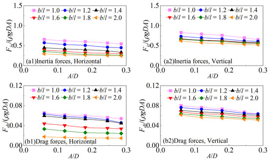
Figure 16.
Comparisons of the inertial and drag forces on the semi-round-corner cylinder under different b/l.
The inertial forces on the cylinders under the same aspect ratio at different wave amplitudes are compared. The cases of the semi-round-corner cylinder with A/D = 0.060, 0.120, 0.180, and 0.245 under various b/l are considered as examples. The comparisons of the inertial forces are shown in Figure 17. As shown in the figures, in the horizontal and vertical directions, the dimensionless inertial forces gradually decrease with the increase in A/D, and this characteristic of the inertial forces is also reflected in the cases with the other section corners and aspect ratios. This leads to the fact that with the increase in A/D, the dimensionless first harmonic horizontal and vertical forces on the cylinders show a gradual decreasing trend. Previous studies have summarized the reason for this phenomenon: because the lift force is close to the opposite direction of the inertial force, the lift effect increases with the increase in the wave amplitude, and the dimensionless wave force on the cylinder decreases.
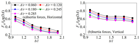
Figure 17.
Comparisons of the inertial forces on the semi-round-corner cylinder at different A/D.
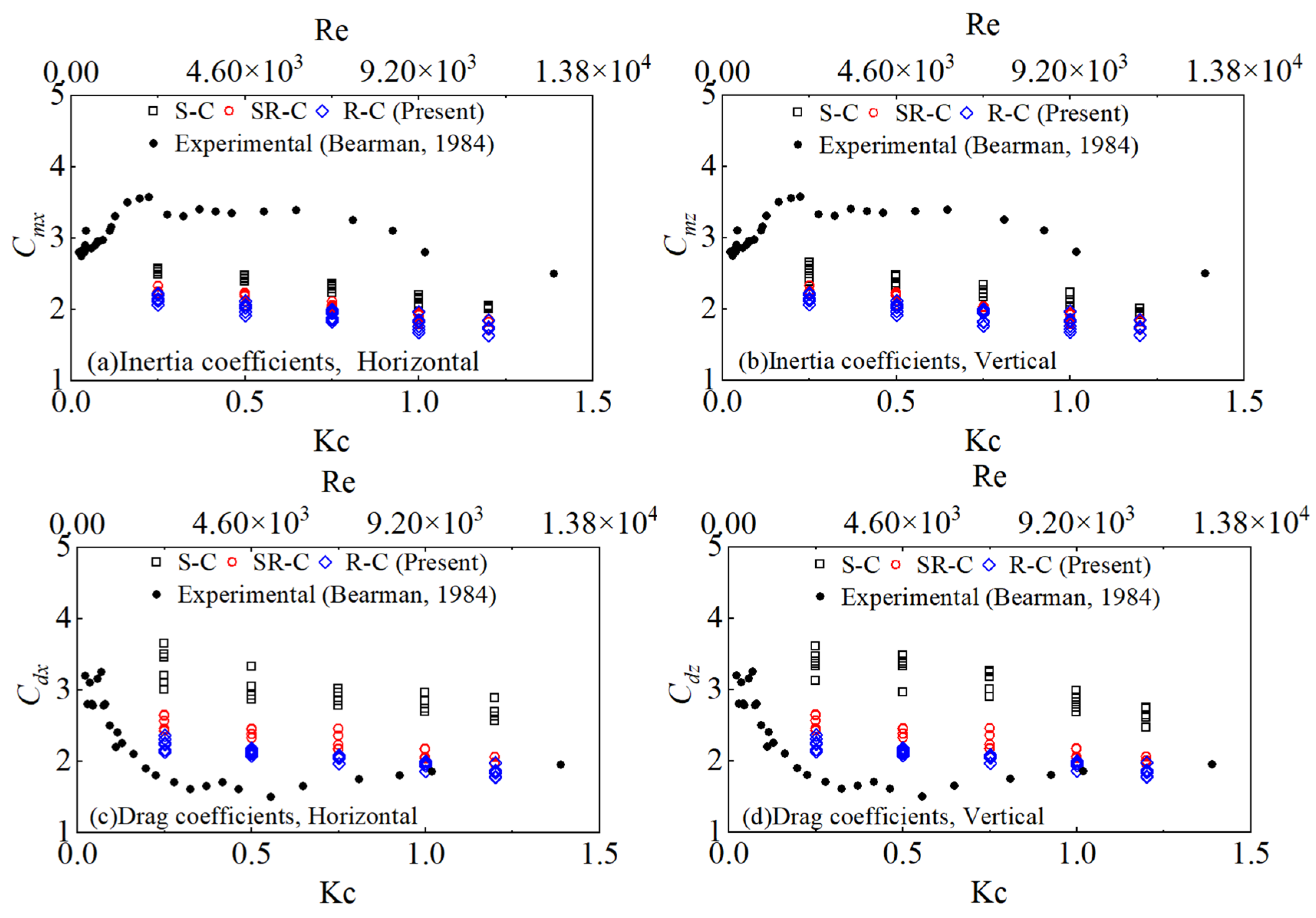
Combining the present numerical results of the inertial and drag forces, the hydrodynamic coefficients are obtained by solving Equations (10) and (11). The inertia and drag coefficients for the wave action on the submerged horizontal cylinders with various section corners and aspect ratios as functions of the Kc and Re numbers are shown in Figure 18. It is concluded that the inertia and drag coefficients all decrease generally with the increase in the Kc and Re numbers. The hydrodynamic coefficients are relatively larger for the cases of the sharp-corner cylinder and relatively smaller for the cases of the round-corner cylinder. Bearman et al. [31] experimentally studied the fluid forces and hydrodynamic coefficients on a horizontal rectangular cylinder in viscous oscillatory flow at low Kc numbers. The maximum values of the coefficients in the study were given as about Cm = 3.57 and Cd = 3.25. The present maximum inertia coefficients in the horizontal and vertical directions are about Cmx = 2.57 and Cmz = 2.68, which are smaller than those from the previous study. The maximum drag coefficients of Cdx = 3.65 and Cdz = 3.61 in the present study are larger than the previous results.
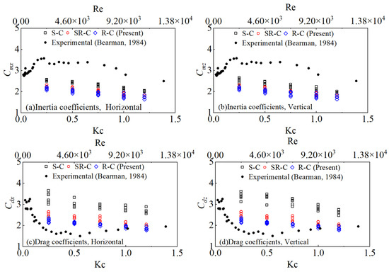
Figure 18.
Hydrodynamic coefficients as functions of Kc and Re [31].
6. Conclusions
This study focuses on the nonlinearity and vortex effects on the high harmonic forces on the submerged horizontal cylinders with various cross-sections. The physical phenomena are explained by analyzing the characteristics of the flow field distribution around the cylinders and comparing the components from the decomposition of the wave forces. The inertia and drag coefficients were obtained by solving Morison’s equation and combining the numerical results. The conclusions drawn from the study are summarized as follows:
- (1)
- There are similar flow field distributions around the semi-round-corner and round-corner cylinders, while the complex and stronger vortices generated around the sharp-corner cylinder cause a significant difference in the pressure distribution. This leads to larger inertia forces, and larger second and third harmonic forces.
- (2)
- Some vortices are generated from the wave action on the submerged horizontal cylinders rotating periodically clockwise around the cylinder. This contributes to the significant nonlinear effect in the higher harmonic forces, especially on the sharp-corner cylinder, and this effect generally becomes greater with the decrease in the aspect ratio.
- (3)
- The hydrodynamic coefficients for the cases of the sharp-corner cylinder are relatively larger, and the coefficients on the round-corner cylinder are relatively smaller. The inertia and drag coefficients increase with the increase in the Kc and Re numbers. The present maximum inertia and drag coefficients, Cm = 2.68 and Cd = 3.65, are different from those in the previous studies.
Author Contributions
Data curation, H.M., G.W. and Y.Y.; funding acquisition, H.M.; writing—original draft preparation, H.M. and J.Z.; writing—review and editing, H.M. and J.Z.; data analysis, J.Z. and G.W.; supervision, G.W. and S.Z.; literature resources, H.C. and Y.Y.; project administration, H.C., S.Z. and Q.Y.; methodology, Q.Y. All authors have read and agreed to the published version of the manuscript.
Funding
This work was financially supported by the National Key Research and Development Program of China [Grant number 2023YFC3008200], the National Natural Science Foundation of China [Grant numbers 52001071 and 42201029], the Guangdong Basic and Applied Basic Research Foundation [Grant numbers 2023A1515010890 and 2022A1515240039], and the Youth Innovative Talents Program of Guangdong Colleges and Universities [Grant number 2022KQNCX026].
Institutional Review Board Statement
Not applicable.
Informed Consent Statement
Not applicable.
Data Availability Statement
No new data were created or analyzed in this study. Data sharing is not applicable to this article.
Conflicts of Interest
Author Qinru Yang was employed by the Hengli Shipbuilding Co., Ltd. The remaining authors declare that the research was conducted in the absence of any commercial or financial relationships that could be construed as a potential conflict of interest.
References
- Chaplin, J.R. Nonlinear forces on a horizontal cylinder beneath waves. J. Fluid Mech. 1984, 147, 449–464. [Google Scholar] [CrossRef]
- Wang, S.D.; Wei, G.; Du, H.; Wu, J.L.; Wang, X.L. Experimental investigation of the wave-flow structure of an oblique internal solitary wave and its force exerted on a slender body. Ocean Eng. 2020, 201, 107057. [Google Scholar] [CrossRef]
- Wang, S.; Du, H.; Wei, G.; Peng, P.; Xuan, P. Experimental modification of the internal solitary wave force exerted on a horizontal transverse cylinder due to wave-flow and vortex shedding. Ocean Eng. 2023, 269, 113513. [Google Scholar] [CrossRef]
- Feng, X. Analysis of higher harmonics in a focused water wave group by a nonlinear potential flow model. Ocean Eng. 2019, 193, 106581. [Google Scholar] [CrossRef]
- Feng, X.; Taylor, P.H.; Dai, S.; Day, A.H.; Willden, R.H.J.; Adcock, T.A.A. Experimental investigation of higher harmonic wave loads and moments on a vertical cylinder by a phase-manipulation method. Coast. Eng. 2020, 160, 103747. [Google Scholar] [CrossRef]
- Hu, J.; Lin, Y.H.; Maza, M. A semi-analytical theory for water waves interacting with a submerged/suspended circular cylinder patch. Ocean Eng. 2022, 247, 110667. [Google Scholar] [CrossRef]
- Tavassoli, A.; Kim, M.H. Interactions of fully nonlinear waves with submerged bodies by a 2D viscous NWT. In Proceedings of the International Ocean and Polar Engineering Conference, ISOPE-I-01-286, Stavanger, Norway, 17–22 June 2001. [Google Scholar]
- Teng, B.; Mao, H.F.; Lu, L. Viscous effects on wave forces on a submerged horizontal circular cylinder. China Ocean Eng. 2018, 32, 245–255. [Google Scholar] [CrossRef]
- Gu, F.; Huang, Y.; Zhang, D. Cavitation of multiscale vortices in circular cylinder wake at Re = 9500. J. Mar. Sci. Eng. 2021, 9, 1366. [Google Scholar] [CrossRef]
- Zhou, X.; Jiang, Q.; Wang, Y.; Chen, L.; Wang, S.; Wang, K. Numerical Simulation of Wave–Current Force Characteristics of Horizontal Floating Cylinder in Heave Motion. J. Mar. Sci. Eng. 2022, 10, 1884. [Google Scholar] [CrossRef]
- Zhou, X.; Jiang, Q.; Wang, K.; Wang, S. Analysis of Horizontal Cylinder Load under Different Conditions in Regards to Waves and Flows. J. Mar. Sci. Eng. 2024, 12, 1101. [Google Scholar] [CrossRef]
- Ding, W.; Sun, H.; Zhao, X.; Ai, C. Numerical investigation of an internal solitary wave interaction with tandem horizontal cylinders. Ocean Eng. 2022, 246, 110658. [Google Scholar] [CrossRef]
- Selvan, S.A.; Gayathri, R.; Behera, H.; Meylan, M.H. Surface wave scattering by multiple flexible fishing cage system. Phys. Fluids 2021, 33, 037119. [Google Scholar] [CrossRef]
- Kushwaha, A.K.; Behera, H.; Gupta, V.K. Wave scattering by a circular cylinder over a porous bed. Arch. Appl. Mech. 2024, 94, 555–570. [Google Scholar] [CrossRef]
- Yang, Z.; Ding, H.; Li, K.; Cheng, L.; Huang, B.; Ren, Q. Experimental Investigation of Wave-Induced Forces on a Large Quasi-Elliptical Cylinder during Extreme Events. J. Mar. Sci. Eng. 2022, 10, 540. [Google Scholar] [CrossRef]
- Venugopal, V.; Varyani, K.S.; Barltrop, N.D.P. Wave force coefficients for horizontally submerged rectangular cylinders. Ocean Eng. 2006, 33, 1669–1704. [Google Scholar] [CrossRef]
- Liu, J.; Guo, A.; Li, H. Analytical solution for the linear wave diffraction by a uniform vertical cylinder with an arbitrary smooth cross-section. Ocean Eng. 2016, 126, 163–175. [Google Scholar] [CrossRef]
- Liu, J.; Guo, A. Wave force identification for a large-scale quasi-elliptical cylinder from monitored wave elevation. Ocean Eng. 2023, 271, 113769. [Google Scholar] [CrossRef]
- Han, H.; Guo, Y.; Huo, R. Semi-analytical solution of transverse vibration of cylinders with non-circular cross-section partially submerged in water. J. Mar. Sci. Eng. 2023, 11, 872. [Google Scholar] [CrossRef]
- Chatjigeorgiou, I.K.; Katsardi, V. Hydrodynamics and near trapping effects in arrays of multiple elliptical cylinders in waves. Ocean Eng. 2018, 157, 121–139. [Google Scholar] [CrossRef]
- Chatjigeorgiou, I.K. Three dimensional wave scattering by arrays of elliptical and circular cylinders. Ocean Eng. 2011, 38, 1480–1494. [Google Scholar] [CrossRef]
- Ai, C.; Ma, Y.; Yuan, C.; Dong, G. Semi-implicit non-hydrostatic model for 2D nonlinear wave interaction with a floating/suspended structure. Eur. J. Mech.-B/Fluids 2018, 72, 545–560. [Google Scholar] [CrossRef]
- Chen, X.; Liang, J.H.; Xu, G.; Chen, Q. A study on the interaction between circular or elliptical cross-section submerged floating tunnels and elevation internal solitary waves. Ocean Eng. 2023, 285, 115291. [Google Scholar] [CrossRef]
- Ding, W.; Sun, H.; Zhao, X.; Ai, C. Numerical study of the interaction between an internal solitary wave and a submerged extended cylinder using OpenFOAM. Ocean Eng. 2023, 274, 113985. [Google Scholar] [CrossRef]
- Jacobsen, N.G.; Fuhrman, D.R.; Fredsøe, J. A wave generation toolbox for the open-source CFD library: OpenFoam®. Int. J. Numer. Methods Fluids 2012, 70, 1073–1088. [Google Scholar] [CrossRef]
- Hur, D.S.; Mizutani, N.; Kim, D.S. Direct 3-D numerical simulation of wave forces on asymmetric structures. Coast. Eng. 2004, 51, 407–420. [Google Scholar] [CrossRef]
- Hieu, P.D.; Katsutoshi, T.; Ca, V.T. Numerical simulation of breaking waves using a two-phase flow model. Appl. Math. Model. 2004, 28, 983–1005. [Google Scholar] [CrossRef]
- Fenton, J.D. A fifth-order Stokes theory for steady waves. J. Waterw. Port Coast. Ocean Eng. 1985, 111, 216–234. [Google Scholar] [CrossRef]
- Brigham, E.O.; Morrow, R.E. The fast Fourier transform. Inst. Electr. Electron. Eng. Spectr. 1967, 4, 63–70. [Google Scholar] [CrossRef]
- Morison, J.R.; Johnson, J.W.; Schaaf, S.A. The force exerted by surface waves on piles. J. Pet. Tec. 1950, 2, 149–154. [Google Scholar] [CrossRef]
- Bearman, P.W.; Graham, J.M.R.; Obasaju, E.D.; Drossopoulos, G.M. The influence of corner radius on the forces experienced by cylindrical bluff bodies in oscillatory flow. Appl. Ocean Res. 1984, 6, 83–89. [Google Scholar] [CrossRef]


Disclaimer/Publisher’s Note: The statements, opinions and data contained in all publications are solely those of the individual author(s) and contributor(s) and not of MDPI and/or the editor(s). MDPI and/or the editor(s) disclaim responsibility for any injury to people or property resulting from any ideas, methods, instructions or products referred to in the content. |
© 2024 by the authors. Licensee MDPI, Basel, Switzerland. This article is an open access article distributed under the terms and conditions of the Creative Commons Attribution (CC BY) license (https://creativecommons.org/licenses/by/4.0/).