Article

Relative Localization and Dynamic Tracking of Underwater Robots Based on 3D-AprilTag

1
Marine Engineering College, Dalian Maritime University, Dalian 116026, China
2
College of Mechanical and Control Engineering, Baicheng Normal University, Baicheng 137000, China
3
Intelligent Biomimetic Design Lab, College of Engineering, Peking University, Beijing 100871, China
*
Authors to whom correspondence should be addressed.
These authors contributed equally to this work.
J. Mar. Sci. Eng. 2025, 13(5), 833; https://doi.org/10.3390/jmse13050833
Submission received: 31 March 2025 / Revised: 18 April 2025 / Accepted: 22 April 2025 / Published: 23 April 2025
(This article belongs to the Section Ocean Engineering)

Abstract

:
This paper presents a visual localization system for underwater robots, aimed at achieving high-precision relative positioning and dynamic target tracking. A 3D AprilTag reference structure is constructed using a cubic configuration, and a high-resolution camera module is integrated into the AUV for real-time tag detection and pose decoding. By combining multi-face marker geometry with a fused state estimation strategy, the proposed method improves pose continuity and robustness during multi-tag transitions. To address pose estimation discontinuities caused by viewpoint changes and tag switching, we introduce a fusion-based observation-switching Kalman filter, which performs weighted integration of multiple tag observations based on relative distance, viewing angle, and detection confidence, ensuring smooth pose updates during tag transitions. The experimental results demonstrate that the system maintains stable pose estimation and trajectory continuity even under rapid viewpoint changes and frequent tag switches. These results validate the feasibility and applicability of the proposed method for underwater relative localization and tracking tasks.

1. Introduction

Marine observation systems integrate multidimensional data acquisition and transmission capabilities, and they are widely applied in scientific research, resource development, and environmental monitoring [1,2]. Traditional fixed observation platforms offer long-term stability but lack adaptability in dynamic, mobile tasks. In contrast, mobile platforms such as Remotely Operated Vehicles (ROVs) and Autonomous Underwater Vehicles (AUVs) provide greater mission flexibility [3,4]. Yet, their deployment in complex underwater tasks remains limited by localization and navigation accuracy.
The current mainstream underwater localization methods primarily rely on acoustic [5] and electromagnetic technologies [6], where the former suffers from high communication latency and poor noise resistance, and the latter rapidly attenuates underwater, limiting its practical use. With its high precision and short-range advantages, visual localization technology has become a key tool for multi-robot collaborative operations in recent years. However, underwater environments with low light, turbidity, and occlusion severely hinder the robustness of natural feature detection [7,8]. Moreover, existing artificial marker systems are primarily based on static or single-plane structures, making them unsuitable for dynamic pose estimation with rapid 3D viewpoint changes [9,10,11].
In the field of artificial visual markers, systems such as ARToolKit [12,13], AprilTags [14,15,16,17,18], and ArUco [19,20] have been widely used. The experimental results show that AprilTags exhibit higher robustness in turbid environments [21], while ARToolKit and ArUco are better suited for clear-water conditions. Based on this, Juan Chen et al. [22] implemented underwater map reconstruction using multi-AprilTags and Extended Kalman Filtering (EKF), while Gideon Billings et al. [23] applied AprilTags for short-term stable localization of underwater robotic tools. However, these methods are mostly limited to static or single-plane tag scenarios. Although Luis A. et al. [24] improved the six-degree-of-freedom (6-DOF) pose estimation with multi-plane AprilTags 3D deployment, their method primarily targets surface vessel formations and struggles to address the challenges of underwater 3D localization in dynamically disturbed environments. The ReTrackVLM architecture proposed by Ertugrul Bayraktar [25] provides an effective multi-object tracking strategy, but its computational overhead in underwater environments still needs further investigation.
To address these limitations, this study proposes a dynamic localization method for underwater robots that utilizes a moving cubic carrier. This method employs four-sided AprilTags to create a 3D reference system and introduces a fusion-based observation-switching Kalman filtering model, which jointly models multi-face observations and motion states, improving pose continuity and robustness under viewpoint switching conditions. Compared to previous static multi-tag systems [22] and surface 3D structure-based localization methods [24], this study is the first to realize omnidirectional robust relative localization for dynamic 3D markers, offering a low-dependency, highly scalable visual perception solution for multi-robot collaboration. The main innovations of this study are as follows:
  • A 3D AprilTag marker based on a moving cubic structure is proposed, overcoming the angle limitations of traditional single-plane markers in dynamic localization. Unlike single-plane systems, which face recognition failure or pose estimation interruptions when the robot’s viewpoint changes, the proposed cubic structure distributes multiple AprilTags across adjacent faces, providing continuous visual references from different angles, enhancing observability, and supporting 6-DOF localization of underwater dynamic targets.
  • A fusion-based observation-switching Kalman filter model is introduced to ensure smooth pose transitions and continuous tracking during rapid tag switching or occlusion. This model dynamically adjusts fusion weights based on observation distance, angle, and detection confidence, addressing pose inconsistencies caused by switching between different tag faces. It significantly improves pose estimation continuity and robustness in dynamic environments with viewpoint changes and partial occlusion.
  • A reconfigurable relative localization framework is developed, demonstrating practicality in dynamic targets and underwater 3D tags, and laying the foundation for future multi-robot collaborative perception and control. The system enables autonomous tracking and navigation without relying on global maps or external base stations, achieving stable pose estimation and trajectory tracking even under dynamic interactions and tag switching. Its scalability and adaptability to various tasks make it suitable for multi-robot systems, providing the basis for low-dependency, high-autonomy underwater collaborative systems.
The rest of this paper is summarized as follows. Section 2 introduces the 3D AprilTag-based relative localization framework. Section 3 analyzes the experimental setup, procedures and results. Section 4 concludes this paper.

2. Three-Dimensional AprilTag-Based Relative Localization Framework

This section provides a detailed description of the proposed 3D-AprilTag visual localization system for underwater tracking and positioning tasks, along with the corresponding underwater robot control methodology. As illustrated in Figure 1, the system architecture comprises core modules for visual localization, motion control, and power management. Regarding visual localization, the system employs 3D-AprilTag as spatial feature recognition references. By leveraging the stable feature points provided by these markers, the system applies the Perspective-n-Point (PnP) algorithm to estimate the pose of the robot’s camera. Specifically, the system first acquires the spatial position and orientation information of the camera, and then computes the underwater robot’s relative pose using homogeneous coordinate transformation matrices. To enhance the system’s robustness, a Kalman filtering algorithm is introduced at marker transition points, effectively smoothing the localization data and ensuring the stability of the robot’s positioning and tracking control.
The underwater robot developed in this study utilizes the STM32F407ZGT6 (STMicroelectronics, Geneva, Switzerland) as the core control microcontroller. The integrated power management system outputs multi-level voltages (24 V, 19 V, 5 V), supplying stable power to various functional modules. The motion control strategy is based on a cascade PID controller architecture, which integrates visual localization pose information with spatial data from other sensors for comprehensive control. The system first applies a second-order low-pass filter to denoise data from the IMU and depth sensors. The filtered data, along with the visual pose information, are then fed into the PID controller. The inner-loop PID is responsible for controlling the robot’s acceleration, while the outer-loop PID governs the robot’s pose. A closed-loop control strategy is adopted, continuously feeding the updated state back into the controller until the desired target pose is achieved. This system design, integrating visual localization with motion control, not only enhances the accuracy and real-time performance of underwater tracking and positioning but also significantly improves the overall system stability and environmental adaptability. It provides a reliable technical foundation for the autonomous operations of underwater robots.

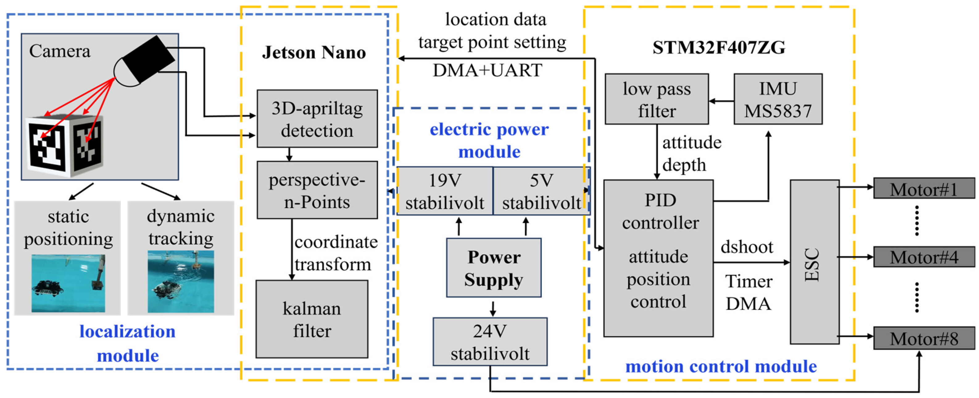
2.1. Underwater Robot Platform
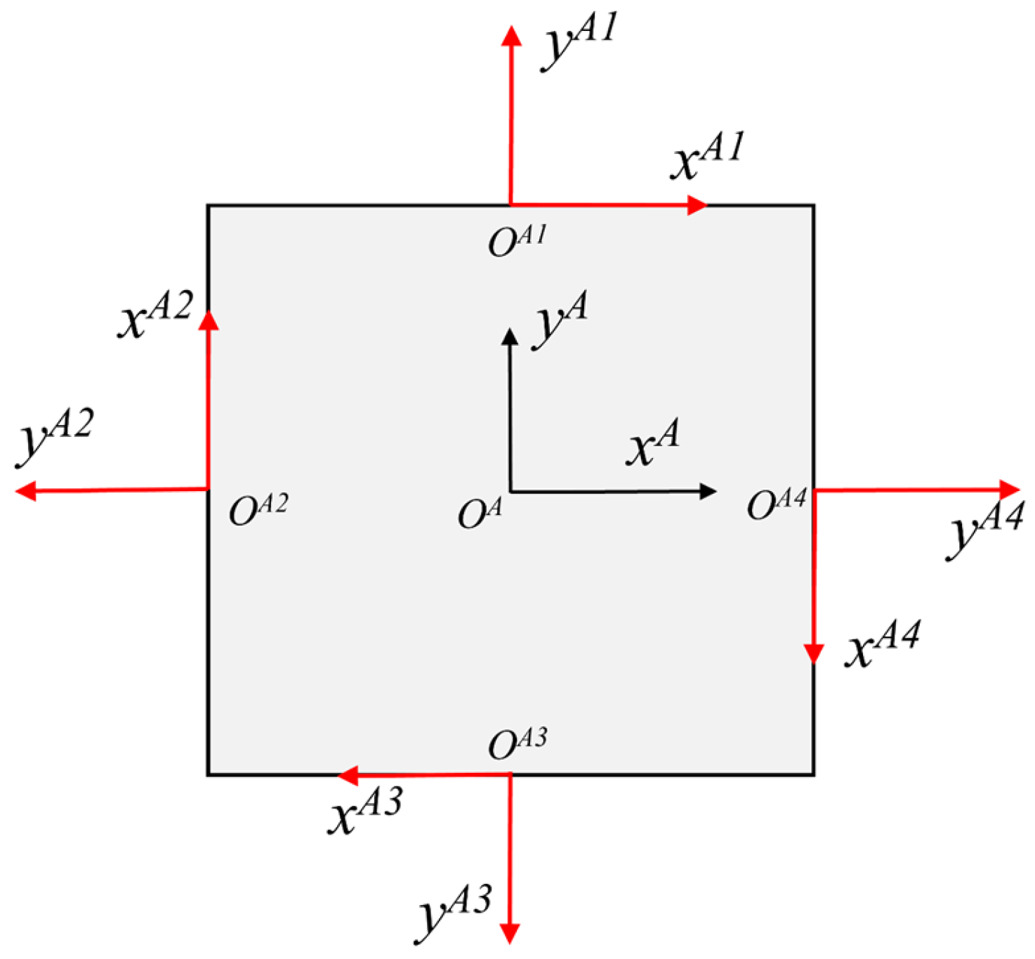
The underwater robot developed in this study has overall dimensions of 35 cm × 33 cm × 30 cm and integrates a camera compartment, a core compartment, and eight thrusters for both horizontal and vertical movement. The core compartment houses essential hardware components such as motion control units, power management systems, and image-processing modules. The camera compartment is constructed from transparent acrylic material, offering an expanded field of view. The camera is capable of rotating around the vertical axis, providing a 360-degree panoramic view for specific tasks. In certain scenarios, the camera can statically switch its field of view, significantly enhancing image acquisition capabilities in underwater environments.
The robot’s motion control system consists of an ARM-based microcontroller unit (MCU), a depth sensor, an inertial measurement unit (IMU), and a motor controller, forming an efficient closed-loop control core. The MCU selected is the STM32F407ZGT6 (STMicroelectronics, Geneva, Switzerland), running the FreeRTOS real-time operating system. Through multi-task scheduling, it efficiently manages sensor data processing and actuator control, ensuring system real-time performance and stability. The depth measurement module employs the MS5837 (Measurement Specialties, Inc., Hampton, VA, USA) high-precision digital pressure and temperature sensor, which compensates pressure data using real-time environmental temperature readings. This significantly enhances the accuracy of pressure measurements, ensuring that the data accurately reflect underwater conditions. The spatial attitude measurement module integrates the YIS320 IMU (Yost Labs, Portsmouth, OH, USA), which includes magnetometers, gyroscopes, and accelerometers to provide high-precision attitude information. The motor control module utilizes a 65A four-in-one Electronic Speed Controller (HAKRC, Shenzhen, China), supporting 24 V voltage input, and is fully compatible with the bidirectional DShot protocol. The power management system comprises a lithium battery, a power distribution board, and voltage regulation modules. The robot is powered by a 24 V 9000 mAh lithium battery, providing approximately 30 min of operational endurance under a full load (with all eight thrusters operating simultaneously). The power distribution board is built with a 60A-rated PCB, capable of handling high-power demands while effectively managing heat dissipation. The voltage regulation module features three independent channels: a 24 V channel dedicated to powering the thruster motors, a 5 V channel supplying stable power to the STM32F407ZGT6 (STMicroelectronics, Geneva, Switzerland), and a separate 24 V regulated channel powering the Jetson Orin NX (NVIDIA Corporation, Santa Clara, CA, USA) to ensure the reliability and efficiency of all functional modules in complex operational environments. The system is equipped with a Jetson Orin NX 16 GB edge computing device and a 2-megapixel industrial-grade global shutter camera. When operating at a resolution of 320 × 240 pixels, the Jetson Orin NX can stably run AprilTag localization algorithms and related data acquisition tasks at a frame rate of 20 FPS, significantly enhancing the visual-processing performance in underwater environments.

2.2. Target Markers

This study presents an efficient visual relative positioning scheme based on the AprilTag visual marker system. AprilTag is a high-performance visual marker technology renowned for its exceptional robustness under varying lighting conditions, partial occlusions, and long-distance detection scenarios. Furthermore, each AprilTag marker possesses a unique identifier, and its detection algorithm is both efficient and straightforward, requiring only minimal preprocessing combined with the AprilTag recognition algorithm to achieve precise identification. These characteristics make AprilTag particularly well-suited for relative positioning tasks. Building upon the single-sided AprilTag system, this research designs and constructs a spatial localization system comprising four markers, tailored to meet the high-precision relative positioning requirements of underwater robots operating in three-dimensional environments.
The AprilTag markers used in this study each measure 10 cm in size. Camera calibration was performed using a 20 cm × 12.5 cm chessboard calibration board with a 9 × 6 grid. To enable three-dimensional spatial localization, four AprilTag markers with IDs 1, 2, 3, and 4 were selected and systematically affixed to the four sides of a cube. This configuration facilitates robust and accurate 3D pose estimation for underwater robotic applications.

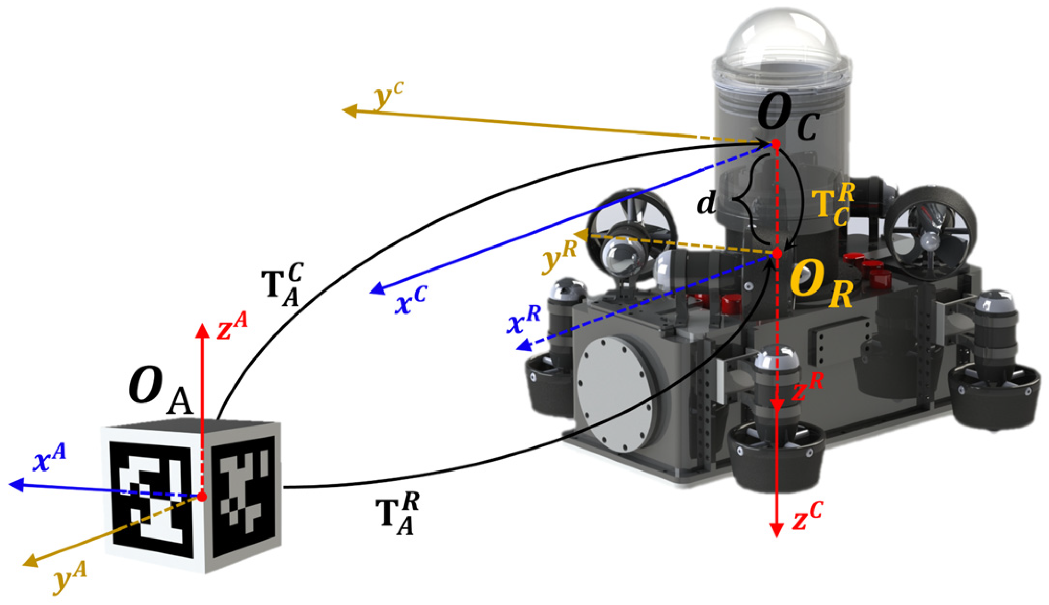
2.3. Coordinate Transformation

To simplify the kinematic modeling of vision-based relative positioning for Autonomous Underwater Vehicles (AUVs), three reference coordinate systems are typically employed, as illustrated in Figure 2.
The visual perception system designed comprises the robot coordinate system, the camera coordinate system, and the AprilTag marker coordinate system. Transitions between these coordinate systems are facilitated through homogeneous transformation matrices [26].

2.3.1. Transformation from Camera to Robot Coordinate System

This coordinate system is fixed to the AUV and moves along with it. The origin, denoted as O R , is located at the AUV’s center of mass. The x R -axis aligns with the longitudinal axis of the vehicle, pointing toward the bow, y R -axis is perpendicular to the longitudinal plane, pointing to the starboard (right) side of the robot, and z R -axis is perpendicular to the O R - x R y R according to the right-hand rule, pointing downward.
The camera coordinate system is rigidly fixed to the underwater robot. The origin of the camera, denoted as O C , is positioned at a distance d directly above the robot coordinate system’s origin O R . Therefore, the homogeneous transformation matrix from the camera to the robot is given by:
T C R = R C R t C R 0 1 × 3 1
Here, R C R represents the rotation matrix from the camera coordinate system {C} to the robot coordinate system {R}, and t C R denotes the translation vector from {C} to {R}.

2.3.2. Transformation from 3D-AprilTag to Camera Coordinate System

The 3D-AprilTag coordinate system is rigidly fixed to the AprilTag marker, with its origin O A located at the center of the 3D-AprilTag structure. As illustrated in Figure 3, the top–down view of the marker shows the x A -axis oriented perpendicular to Tag 4, pointing outward from the marker’s surface. The y A -axis is perpendicular to the x A -axis, aligned with the outward normal of Tag 1. The z A -axis follows the right-hand rule, perpendicular to the O A - x A y A , and points vertically upward. The coordinate system is represented as follows.
The camera, mounted within the robot’s camera compartment via a gimbal, captures and recognizes the AprilTag markers, enabling the calculation of the coordinate transformation from the single-sided AprilTag to the camera:
T A i C = R A i C t A i C 0 1 × 3 1
In this transformation, R A i C represents the rotation matrix from the AprilTag single-sided coordinate system {Ai} (where i = 1, 2, 3, 4) to the camera coordinate system {C}, while t A i C denotes the translation vector from the AprilTag single-sided marker to the camera.
For the coordinate systems of the other four marker faces, assume the cube-shaped AprilTag has an edge length of L A . The four single-sided marker coordinate systems {Ai} are located at the centers of the cube’s side faces, while the overall coordinate system {A} is positioned at the geometric center of the cube. To establish the relationship between {A} and {Ai}, it is necessary to define both rotational and translational transformations.
The transformation matrix from the central coordinate system {A} to each single-sided marker coordinate system {Ai} can be expressed as follows:
T A A i = R A A i t A A i 0 1 × 3 1
Here, R A A i represents the rotation matrix, which can be expressed in its general form as follows:
R A A i = c o s   φ A i s i n   φ A i 0 s i n   φ A i c o s   φ A i 0 0 0 1
The angle φ A i denotes the rotation from the central coordinate system {A} to the individual marker coordinate systems {Ai}. Specifically, the coordinate systems {A1}, {A2}, {A3}, and {A4} are rotated around the z A -axis by angles of 0, π / 2 , π , and π / 2 , respectively.
Similarly, t A A i represents the translation vector, which can be expressed as follows:
t A A i = ( x A A i , y A A i , z A A i ) T
The components x A A i , y A A i , z A A i correspond to the relative coordinates along the x, y, and z axes from the coordinate systems {A} to {Ai}, taking values of L A /2 or − L A /2 depending on the face orientation. Since all coordinate systems are positioned within the xy-plane, the z-axis displacement z A A i is zero.

2.3.3. Transformation from AprilTag to Robot Coordinate System

Relative positioning refers to determining the position and orientation of the Autonomous Underwater Vehicle with respect to the AprilTag marker. By capturing the AprilTag marker with the camera and performing pose estimation, the relative position coordinates and orientation between the AUV and the AprilTag marker can be derived.
To compute relative positioning, it is necessary to establish the transformation relationships between the respective coordinate systems. This involves three primary transformation matrices: first, the transformation matrix from the AprilTag coordinate system {A} to the individual AprilTag marker coordinate system {Ai}; second, the transformation matrix from the individual AprilTag marker coordinate system {Ai} to the camera coordinate system {C}; and finally, the transformation matrix from the camera coordinate system {C} to the robot coordinate system {R}. By combining these transformation matrices between the underwater robot, camera, and AprilTag markers, the overall transformation from the AprilTag coordinate system {A} to the robot coordinate system {R} can be expressed as follows:
T A R = R A R   t A R   0 1 × 3 1 = T A A i · T A i C · T C R   = R A A i · R A i C · R C R R A A i · R A i C · t C R + R A A i · t A i C + t A A i 0 1 × 3 1
Here, the product T A A i · T A i C · T C R represents the cumulative effect of the three transformations: from {A} to {Ai}, from {Ai} to {C}, and finally from {C} to {R}.
Through the above calculations, the complete transformation matrix from the AprilTag coordinate system {A} to the robot coordinate system {R} can be obtained, encompassing both rotational and translational components. This method sequentially combines rotation matrices and translation vectors to achieve the transformation from the AprilTag coordinate system to the robot coordinate system.

2.4. Relative Pose Estimation

To transform a point from the AprilTag coordinate system to the robot coordinate system, consider a point P A = [ x A , y A , z A ] T in the AprilTag coordinate system { A } . Its corresponding position P R = [ x R , y R , z R ] T in the robot coordinate system { R } is calculated using the following equation:
P R = R A R · P A + t A R
In this equation, two types of transformations are involved. The first is the application of the rotation matrix R A   R , which translates the orientation information of the AprilTag marker into the robot coordinate system. The second is the application of the translation vector t A R , which converts the positional information of the AprilTag marker to the robot coordinate system. Once the point has been transformed into the robot coordinate system, the Euclidean distance between the robot and the AprilTag marker can be calculated using the standard Euclidean distance formula:
d r e l = ( x R x A ) 2 + ( y R y A ) 2 + ( z R z A ) 2
In this context, ( x R   , y R   , y R ) represents the coordinates of the AUV, while ( x A   , y A   , y A ) represents the coordinates of the AprilTag marker. Taking the heading angle as an example, it can be calculated by applying the arctangent function to determine the AUV’s orientation relative to the AprilTag marker on the horizontal plane:
θ R A = a r c t a n 2 ( y R y A , x R x A )
The relative pose describes the orientation and attitude angles of the AUV with respect to the AprilTag marker, including roll, pitch, and yaw. These relative orientations can be obtained through differences in the pose matrices or direct measurements. As previously established, the rotation matrix R R E was formulated to describe the transformation. The AprilTag coordinate system {A} pose, captured via the visual sensor, is transformed into the robot coordinate system through the rotation matrix R A R . Consequently, the AUV’s relative pose with respect to the AprilTag marker can be expressed as follows:
R r e l = ( R A R ) T · R R E
Through this formulation, both the relative position and relative orientation between the AUV and the AprilTag marker can be accurately determined. These parameters are crucial for underwater robot navigation and task execution in complex environments. Additionally, when the robot is performing specific trajectory tasks, temporary gaps or discontinuities in observational data between adjacent AprilTag coordinate systems may cause trajectory jitter. To mitigate these fluctuations and ensure smooth transitions, Kalman filtering techniques are employed. By leveraging time series data and prior knowledge, the filter estimates and corrects the robot’s state, enabling precise transitions between adjacent AprilTag markers.

2.5. Integrated Observation-Switching Filter Model

To effectively address the observational uncertainties arising from dynamic AprilTag switching scenarios and achieve smooth fusion of visual cues, this section embeds a weighted fusion observation mechanism into the predictive-update iterative framework of the Kalman filter. This probabilistic transition strategy ensures continuity in the estimated trajectories during sensor observation handovers.
In underwater robotic relative localization using AprilTag markers, autonomous vehicles frequently require dynamic transitions between multiple tags distributed on different faces of a cubic structure. Conventional Kalman filters, which rely on single-observation sources for state updates, often induce sudden discontinuities in pose and positional estimates during tag transitions. Such abrupt changes compromise the continuity of subsequent trajectory prediction and control. To mitigate this, we propose a weighted fusion observation Kalman filter algorithm incorporating a smooth transition mechanism, thereby enabling continuous pose estimation at tag-switching boundaries. As a Bayesian filter inherently performing the recursive estimation of state variables [27], the system is modeled by the following state-space formulation:
x k = F k x k 1 + B k u k + w k
Here, x k R n denotes the system state vector, encompassing position, velocity, and orientation; F k represents the state transition matrix; B k u k corresponds to the control input matrix; and w k ~ N ( 0 , Q k ) characterizes the process noise covariance matrix.
The observation equation is defined as follows:
z k ( i ) = H k x k + v k ( i ) ,   i { 1 , 2 , , N }
Here, z k ( i ) denotes the measurement acquired by the underwater robotic camera from the i -th AprilTag fiducial marker, H k represents the observation matrix, and v k ( i ) ~ N ( 0 , R k ( i ) ) characterizes the observation noise covariance.
It is assumed that the underwater robot detects multiple AprilTag markers (indexed as i = 1 , 2 , , N ) in the current frame, where each marker provides a set of relative pose observations z k ( i ) . The weighted fusion observation z k f u s e d is defined as follows:
z k f u s e d = i = 1 N ω k ( i ) · z k ( i )
The weighting coefficients w k ( i ) are determined by the following three criteria:
  • Distance-based weighting. The estimation reliability inversely correlates with the relative distance between the underwater robot and the AprilTag marker. Closer proximity yields higher confidence in pose observations. This relationship is formulated as follows:
f k ( i ) = e x p ( α · d k ( i ) )
  • View-angle-based weighting. The observation reliability positively correlates with the alignment between the tag’s surface normal vector and the camera’s optical axis. A smaller angular deviation indicates higher geometric consistency for pose estimation. This dependency is modeled as follows:
f θ ( i ) = e x p ( β · θ k ( i ) )
  • Detection confidence weighting. This weighting factor is derived from the intrinsic confidence metric provided by the AprilTag detector, which quantifies the decoding certainty of the fiducial marker. The confidence of AprilTag detection is calculated through a combination of the error correction bits and decoding score: the reliability of error correction is measured by dividing 1 by (1 plus the number of error correction bits), with smaller values indicating more stable results. This value is multiplied by the decoding score percentage (higher scores indicate better matching quality). The final value approaches 1 as the confidence increases, and detections with confidence below 0.3 are typically discarded as low-quality detections. The confidence value c [ 0,1 ] for the i-th tag is incorporated as follows:
f s ( i ) = c k ( i )
By synthesizing these three factors, the final fused weight for each marker is obtained through normalization of their weighted product across all criteria:
ω k ( i ) = f d ( i ) · f θ ( i ) · f s ( i ) j = 1 N f d ( j ) · f θ ( j ) · f s ( j )
This mechanism ensures a natural smooth transition between two adjacent tag observations during switching events, thereby effectively mitigating abrupt pose estimation jumps. In the fusion-based observation-switching model, parameters α and β in the weighting function regulate the system’s sensitivity to tag observation distances and angular deviations, respectively. To achieve stable and robust observation fusion in practical underwater environments, the parameters are configured through a hybrid empirical and data-driven approach. The preliminary experimental results demonstrate that superior tag-switching smoothness and pose estimation continuity are attained in typical underwater scenarios when α = 3.0 and β = 2.0 .
Building upon the fused observation framework, this work adapts the state estimation process of the conventional Kalman filter. The principal modification lies in the observation update phase, where a weighted fusion of measurements from two adjacent tags replaces the single-tag observation vector. This mitigates discontinuities induced by abrupt observation source transitions. The revised filtering procedure comprises three sequential phases.
  • State prediction phase
The current state estimate is propagated based on the previous state and the system dynamics model:
x ^ k k 1 = F k x ^ k 1 k 1 + B k u k
P k k 1 = F k P k 1 k 1 F k T + Q k
where x ^ k k 1 denotes the predicted state estimate at time step k , and P k k 1 represents the predicted covariance matrix.
2.
Observation fusion phase
Independent pose observations z k ( i ) and z k ( i + 1 ) , acquired from two concurrently visible AprilTags, are adaptively fused to formulate a smoothly transitioned observation vector:
z k f u s e d = ω k ( i ) z k ( i ) + ω k ( i + 1 ) z k ( i + 1 )
This refinement significantly enhances system robustness during observation transitions and ensures improved continuity in pose estimation.
3.
State update phase
The predicted state estimate is updated using the fused observation vector z k f u s e d :
K k = P k k 1 H k T ( H k P k k 1 H k T + R k ) 1
x ^ k k = x ^ k k 1 + K k ( z k f u s e d H k x ^ k k 1 )
P k k = ( I K k H k ) P k k 1
where K k denotes the Kalman gain matrix and R k represents the observation noise covariance matrix. Notably, in practical implementations, R k (process noise covariance) can be dynamically adjusted based on tag detection confidence, viewing angle, and relative distance to enhance the filter’s adaptiveness to varying observation quality. A detailed algorithmic workflow is provided in Algorithm 1.
Algorithm 1. Weighted fusion Kalman filter with full annotations
Input:  x ˆ 0 | 0 , P 0 | 0 , { z k ( i ) , d k ( i ) , θ k ( i ) , c k ( i ) } i = 1 N , α , β
           Constants:  F k , B k , u k , Q k , H k , { R k ( i ) }
Output:  x ˆ k | k , P k | k
        Initialization:  x ˆ 0 | 0 , P 0 | 0
1:    for  k = 1 to K do:
2:           Predict Step:
3:              x ˆ k | k 1 F k x ˆ k 1 | k 1 + B k u k
4:              P k | k 1 F k P k 1 | k 1 F k T + Q k
5:           Observation Fusion:
6:              ω total 0
7:           for i = 1 to N do
8:                                                 f d ( i ) e x p ( α d k ( i ) )
9:                                                 f θ ( i ) e x p ( β θ k ( i ) )
10:                                             ω ( i ) f d ( i ) f θ ( i ) f k ( i )
11:                                             ω total ω total + ω ( i )
12:           end for
13:                             z k fused 0 ,   R k 0
14:           for i = 1 to N do
15:                                               ω k ( i ) ω ( i ) / ω total
16:                                               z k fused z k fused + ω k ( i ) z k ( i )
17:                                               R k R k + ( ω k ( i ) ) 2 R k ( i )
18:           end for
19:           Update Step:
20:                             K k P k | k 1 H k T ( H k P k | k 1 H k T + R k ) 1
21:                             x ˆ k | k x ˆ k | k 1 + K k ( z k fused H k x ˆ k | k 1 )
22:                             P k | k ( I K k H k ) P k | k 1
23: end for
In summary, the proposed filtering framework not only preserves the optimal linear estimation properties inherent to the Kalman filter but also achieves effective fusion of multi-tag observations. This dual capability substantially enhances localization smoothness and operational robustness in underwater robotic operations under dynamic tag-switching scenarios.

3. Results and Discussion

This section presents the experimental setup and the stability analysis of both static and dynamic tracking experiments. Furthermore, we observe and discuss the impact of various AprilTag parameters on pose estimation. The experimental setup is thoroughly detailed, including the dimensions of the testing pool, the distribution of global cameras, and specific environmental parameters. The testing pool measures 6.0 m × 4.0 m × 1.6 m, with a coordinate frame mounted above the water surface capable of moving in all directions at controlled speeds. AprilTag is attached to a linkage structure on this coordinate frame to execute predefined movements for tracking experiments. Global underwater motion capture cameras are positioned near the four corners of the pool to monitor the movement of underwater objects. Illumination in the experimental area is provided by incandescent lamps with an intensity of 2000 lumens.
The static experiments were designed to test the recognition range of AprilTag of varying sizes to determine the optimal marker dimensions for localization. Additionally, localization experiments were conducted using different reference points, where incremental x, y, and z values were set, and static localization errors were measured using the underwater robot designed in this study to verify the system’s accuracy. The dynamic tracking experiments involved tracking different trajectories and performing spatial position transformations to assess the potential of the proposed system in practical applications.

3.1. Relative Positioning

As illustrated in Figure 4, the AprilTag marker was fixed in position, and the underwater robot was controlled to explore the relationship between the size of the AprilTag marker and its recognition range. Table 1 presents the maximum recognition distances of the underwater robot for AprilTag of different sizes, with measurements taken along both the x-axis and y-axis. It is evident from the data that larger AprilTag markers correspond to greater maximum recognition distances. Furthermore, the recognition distances are significantly longer along the y-axis (facing directly toward the AprilTag) compared to the x-axis. However, when the AprilTag size increases beyond a certain point (e.g., 12 cm × 12 cm), the gains in recognition distance become marginal. In contrast, recognition distances along the x-axis are shorter, approximately one-third of those along the y-axis. This phenomenon can be attributed to the fact that as the AprilTag size increases, the marker presents a larger surface area, allowing the camera to capture more feature information, thereby facilitating recognition at greater distances. Nevertheless, once the marker size surpasses a certain threshold, the effectiveness of further size increases diminishes due to the limitations of the camera’s field of view and optical performance. Beyond this point, enlarging the marker no longer significantly enhances recognition distances. Additionally, the longer recognition distances along the y-axis (the direction facing the AprilTag) may be due to better viewing angles and higher resolution from the camera’s perspective in this direction. Conversely, recognition distances along the x-axis are shorter due to angular disparities. It is important to note that this discussion focuses solely on cases where the camera is perpendicular to the xₐ-axis of the AprilTag marker. If the underwater robot adjusts its orientation (e.g., pitch or yaw), the system can detect markers at maximum pitch and yaw angles exceeding 80°.
Although larger AprilTag markers facilitate recognition by the underwater robot, excessively large markers may have adverse effects on the underwater environment. Based on the above analysis, a 10 cm × 10 cm AprilTag was selected for this study. This marker size meets the required localization accuracy while providing a more optimal field of view and recognition range. Additionally, while the 10 cm × 10 cm tag delivers sufficient recognition precision, the incremental improvement in recognition distance offered by a 12 cm × 12 cm tag becomes marginal. Therefore, the 10 cm × 10 cm marker represents a more balanced choice.
To evaluate the relative positioning accuracy of the underwater robot with respect to the AprilTag marker, six relative positioning points were selected, as illustrated in the corresponding Figure 4. Relative localization accuracy refers to the precision of measuring the position of an object relative to a specific reference (such as a predefined AprilTag marker). The core of this is to achieve high-precision alignment in the local space through the geometric relationships of visual markers rather than relying on a global absolute coordinate system. Using AprilTags as a local reference allows for the tracking of moving targets. The AprilTag marker was placed at a fixed depth in the testing pool, and the underwater robot was assigned specific relative positioning tasks. For each point, 20 trials of relative positioning were conducted. The pool was equipped with four global motion capture cameras, which were used to record the underwater robot’s relative position to the AprilTag marker during static experiments and to capture the robot’s global position within the experimental area during dynamic experiments.
The motion capture recognition error refers to the difference between the actual position recognized by the visual system and the expected position (the robot’s position relative to the AprilTag marker) when the absolute position of the underwater robot is identified and estimated through the global camera setup in the pool. This error typically arises from various factors, such as sensor accuracy, calibration errors, environmental noise, and algorithm limitations. This difference is represented by two results: the first is the mean value, which is calculated by using the motion capture system to recognize the robot’s relative spatial position to the AprilTag marker, taking the average of 20 measurements. The second is represented by the variance, which is the variance in the position measurement values identified by the motion capture system relative to the AprilTag marker, compared to the expected coordinate values, also averaged over 20 measurements., and the detailed experimental results are summarized in Table 2.
Table 2 quantifies the positioning accuracy of the underwater robot relative to the AprilTag marker, where ( x d ,   y d ,   z d ) represents the expected relative positioning coordinates. The error statistics for each positioning point were obtained from the motion capture system, based on 20 repeated trials for each location. The recorded errors include both the mean and variance. As shown in Table 2, when the positioning trials are conducted along a single axis of the AprilTag coordinate system, the positioning accuracy is relatively high. However, as the number of axes involved in the positioning increases, a slight decline in accuracy is observed. Despite this, the highest recorded accuracy reaches 95.74%, with an error margin of approximately 0.85 cm. This reduction in accuracy is primarily due to error accumulation in multi-axis measurements. While single-axis measurements maintain high precision, simultaneous measurements across multiple axes result in cumulative errors that interact across different directions. Additionally, the inherent limitations of the motion capture system’s precision and systematic errors contribute to the reduced accuracy in multi-axis measurements, thereby affecting overall localization performance. Furthermore, as the relative distance along each axis increases, the positioning error tends to grow. This can be attributed to the amplified influence of multiple factors on system accuracy at greater distances. Firstly, the sensor resolution and sensitivity may decrease with increased distance, leading to larger measurement errors. Secondly, environmental factors such as lighting conditions, noise, and underwater disturbances exert greater influence on sensor performance over longer distances, further degrading positioning accuracy.
Building upon the findings from the relative positioning experiments, the underwater robot was assigned a spatial spiral trajectory navigation task around a central AprilTag marker to validate its relative positioning capabilities. In this task, the initial point is located above the spiral trajectory, as illustrated in Figure 5. Specifically, in the O A - x A y A plane, the underwater robot performs a uniform circular motion around the coordinate system center O A of the AprilTag marker. Simultaneously, along the z A -axis, a series of predefined coordinate values on the spatial spiral trajectory are set, enabling the robot to navigate in a controlled spiral path. This design allows the underwater robot to perform real-time corrections to its position relative to the AprilTag marker, thereby ensuring precise navigation. The system continuously adjusts the robot’s trajectory based on relative pose feedback from the AprilTag markers, achieving accurate tracking even in dynamic environments. The specific navigation outcomes are presented in the accompanying figure.
Figure 5 illustrates the spiral trajectory navigation task involving two complete circular motions. In this task, the underwater robot performs relative positioning using the AprilTag markers based on predefined coordinate values along the y A -axis while simultaneously tracking target points along the z A -axis to achieve precise spatial spiral navigation. Despite the successful application of Kalman filtering to ensure smooth transitions between the two vertically aligned markers, slight trajectory jitters are still observable in the figure. Throughout the two full revolutions around the markers—corresponding to the repeated recognition of four intersection lines—the robot exhibited eight brief and minor jitters. Nevertheless, the robot successfully completed the navigation task, demonstrating the robustness of the navigation system. To provide a clearer depiction of the tracking process, the trajectory and velocity components in all three directions were analyzed, with the specific results presented in Figure 6 and Figure 7.
The motion patterns along the x A and y A directions exhibit simple harmonic motion curves. Notably, a jitter is observed near the intersections of the vertically aligned AprilTag markers. This jitter primarily arises from accumulated relative positioning errors and sensor observation discontinuities in these regions. When the robot transitions from one marker to another, the sensors may fail to update the positional information in real time, resulting in brief localization errors during the switching process. Particularly near the junctions of two vertical markers, the robot is influenced simultaneously by multiple coordinate axes, and this interwoven motion pattern leads to localized jitters in the harmonic curves. Although Kalman filtering has been applied to smooth transitions, slight jitters may still occur due to measurement delays and error propagation during rapid switching. In contrast, along the z A direction, the robot exhibits a trend of uniform downward motion, with specific velocity variations depicted in the figure below, and the velocity along the z A -axis direction is approximately 0.1576 cm/s.
The analysis above is primarily based on static AprilTag markers for relative positioning experiments. However, in practical applications, AprilTag markers are typically fixed to target objects to enable underwater robots to track these targets, adding greater real-world relevance. For instance, tasks such as underwater robot docking with unmanned surface vessels or multi-underwater robot collaborative operations require this dynamic tracking capability.

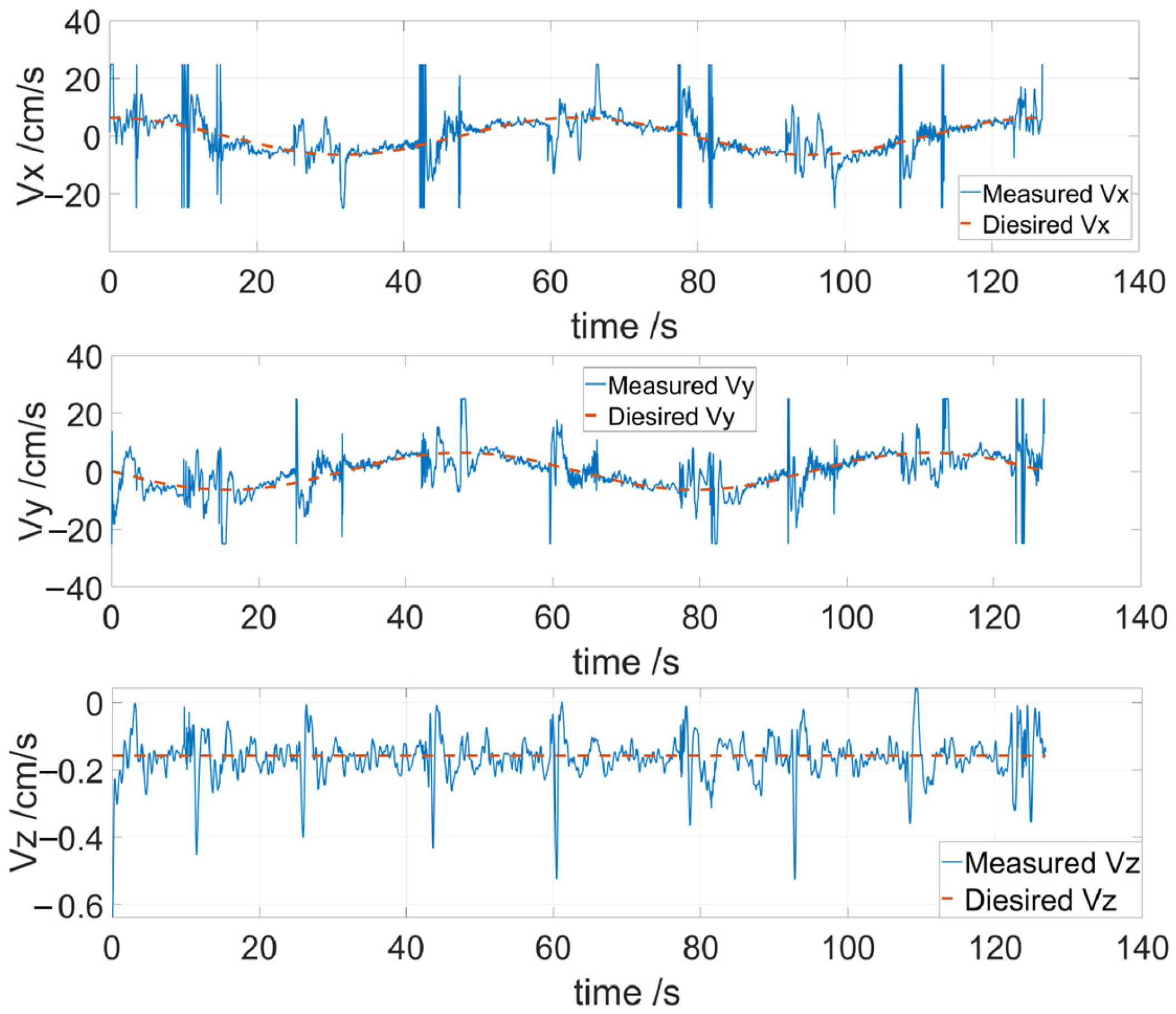
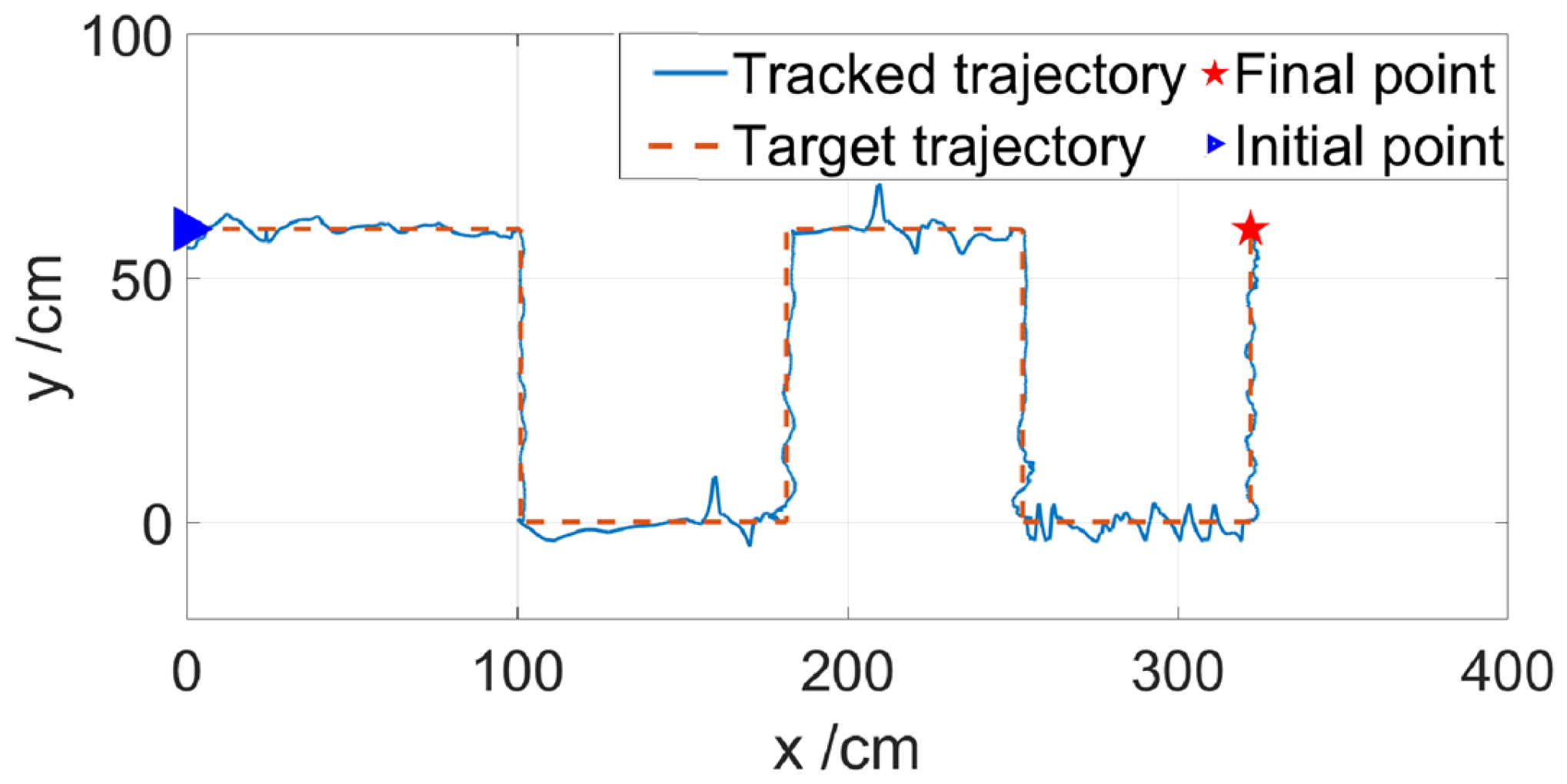
3.2. Dynamic Tracking

To address these practical scenarios, we designed a tracking experiment based on dynamic AprilTag markers. Specifically, the AprilTag marker was affixed to the underside of a coordinate frame and submerged in water, while the coordinate frame was programmed to follow a zigzag trajectory. The underwater robot was tasked with performing real-time tracking of the AprilTag marker to complete target localization and navigation.
As shown in Figure 8, the red dashed line represents the underwater robot’s desired tracking trajectory relative to the AprilTag marker. Although the actual trajectory of the AprilTag marker is not explicitly displayed, it mirrors the robot’s expected tracking path, differing only by a constant relative distance. The blue solid line indicates the measured trajectory of the underwater robot. It is evident that even with the AprilTag marker in motion, the underwater robot successfully follows the marker, completing the tracking task with a maximum error of approximately 10 cm.
Target tracking represents a fundamental application of relative positioning technology. However, its use in enabling collaborative tasks between underwater robots holds even greater practical significance. For instance, during specific missions, an underwater robot may be required to track another underwater robot equipped with an AprilTag marker while maintaining parallel motion. Due to task constraints, the tracking robot must rely on its visual perception system to follow the target robot from behind. In such cases, the tracking robot must employ spatial markers for spatial position transformations. These scenarios are common in multi-underwater robot collaborative tasks or formation transformations within underwater robot swarms. To address these task environments, further experimental validation was conducted.
As illustrated in Figure 9, D represents the underwater robot’s coordinates relative to the AprilTag marker, two blue dashed lines divide the entire task into three phases. During the 0 to 37 s interval, the underwater robot and the AprilTag marker moved parallel to the left, maintaining a constant distance of 60 cm from Tag 1 along the y A 1 -axis. Between 37 and 53 s, the underwater robot’s relative position to the AprilTag marker changed, transitioning from the side of Tag 1 (parallel motion) to the rear of Tag 2 (tracking motion). As the position shifted, the robot’s attitude adjustments caused fluctuations in its depth, as shown in Figure 9. After 53 s, the underwater robot completed its relative position transformation. At this point, the x- and y-axes of Tags 1 and 2 were exchanged (as depicted in the coordinate diagram), resulting in the underwater robot’s position along the y A 1 -axis relative to Tag 1 becoming 0, while its position along the y A 2 -axis relative to Tag 2 was 60 cm. This demonstrates the underwater robot’s ability to successfully execute dynamic position switching relative to a moving AprilTag marker.

4. Conclusions

This study proposes a vision-based relative localization system for underwater robots to enhance the flexibility and localization accuracy of robots in target tracking and cooperative tasks. The system integrates three key technologies: (1) an underwater robot equipped with visual perception capabilities, capable of high-precision recognition of AprilTag markers and real-time control feedback; (2) the construction of a 3D AprilTag marker system tailored for aquatic environments, ensuring stable spatial pose transformations within the robot’s field of view; (3) the introduction of a triple-coordinate transformation method to achieve precise mapping between the AprilTag coordinate system and the underwater robot coordinate system, enabling free pose transformations of the robot relative to the markers; (4) the establishment of a fusion-based observation-switching Kalman filter model to improve pose continuity and anti-interference capabilities under viewpoint switching conditions. The system’s high-precision performance was validated through pool experiments. Under a forward distance of 80 cm to the AprilTag marker, the maximum localization accuracy of the system reached 95.74%, with errors controlled within 0.85 cm. Despite slight jittering observed at the intersection of vertical markers, the robot completed a spatial spiral trajectory navigation task. Additionally, the robot demonstrated good stability while performing zigzag tracking of the AprilTag markers, maintaining an error margin within 10 cm. The system also supports dynamic position switching relative to AprilTag markers according to the requirements of cooperative tasks.
However, the proposed strategy has drawbacks, such as strong environmental dependence and limited observation range and scale. Future research will further explore the feasibility of integrating AprilTag markers into the underwater robot’s body to validate the practicality of multi-robot cooperative control systems in complex environments. With the continued development of visual sensor technology, the system’s perception range is expected to meet the practical demands of multi-robot tasks in applications such as marine monitoring. Through the innovative application of high-precision, stable visual perception technology, and 3D AprilTag markers, this study provides critical theoretical foundations and technical support for the continued evolution of underwater robot swarm technology.

Author Contributions

G.T., T.Y. and Y.Y. contributed equally to this work; G.T. and Q.Z. wrote the main manuscript text; T.Y. and M.X. conceived the experiments; G.T. and T.Y. conducted the experiments; G.X. reviewed the manuscript; Y.Y. processed the data; Q.Z., M.X. and G.X. supervised the project. All authors have read and agreed to the published version of the manuscript.

Funding

This research was funded by the Application Research Program of Liaoning Province (grant No. 2022JH2/101300219), the Natural Science Foundation of Jilin Province (grant No. YDZJ202301ZYTS420), and the Jilin Provincial Department of Education Outstanding Youth Fund (grant No. JJKH20240038KJ).

Data Availability Statement

The original contributions presented in this study are included in this article. Further inquiries can be directed to the corresponding author.

Acknowledgments

The flume tests in this study were conducted in the Marine Self-Powered System Lab.

Conflicts of Interest

The authors declare no conflicts of interest.

References

  1. Majumder, A.; Losito, M.; Paramasivam, S.; Kumar, A.; Gatto, G. Buoys for Marine Weather Data Monitoring and LoRaWAN Communication. Ocean. Eng. 2024, 313, 119521. [Google Scholar] [CrossRef]
  2. Valdés, L.; Bode, A.; Latasa, M.; Nogueira, E.; Somavilla, R.; Varela, M.M.; González-Pola, C.; Casas, G. Three Decades of Continuous Ocean Observations in North Atlantic Spanish Waters: The RADIALES Time Series Project, Context, Achievements and Challenges. Prog. Oceanogr. 2021, 198, 102671. [Google Scholar] [CrossRef]
  3. Stenvers, V.I.; Sherlock, R.E.; Reisenbichler, K.R.; Robison, B.H. ROV Observations Reveal Infection Dynamics of Gill Parasites in Midwater Cephalopods. Sci. Rep. 2022, 12, 8282. [Google Scholar] [CrossRef]
  4. Zhao, Q.; Yang, T.; Tang, G.; Yang, Y.; Luan, Y.; Wang, G.; Wan, T.; Xu, M.; Li, S.; Xie, G. Hierarchical Model for an AUV Swarm with a Leader. Pol. Marit. Res. 2025, 32, 71–80. [Google Scholar] [CrossRef]
  5. Olivastri, E.; Fusaro, D.; Li, W.; Mosco, S.; Pretto, A. A Sonar-Based AUV Positioning System for Underwater Environments with Low Infrastructure Density. arXiv 2024, arXiv:2405.01971. [Google Scholar]
  6. Ali, M.A.; Kaja Mohideen, S.; Vedachalam, N. Current Status of Underwater Wireless Communication Techniques: A Review. In Proceedings of the 2022 Second International Conference on Advances in Electrical, Computing, Communication and Sustainable Technologies (ICAECT), Bhilai, India, 21–22 April 2022; IEEE: Piscataway, NJ, USA, 2022; pp. 1–9. [Google Scholar]
  7. Couturier, A.; Akhloufi, M.A. A Review on Absolute Visual Localization for UAV. Robot. Auton. Syst. 2021, 135, 103666. [Google Scholar] [CrossRef]
  8. Wei, Q.; Yang, Y.; Zhou, X.; Fan, C.; Zheng, Q.; Hu, Z. Localization Method for Underwater Robot Swarms Based on Enhanced Visual Markers. Electronics 2023, 12, 4882. [Google Scholar] [CrossRef]
  9. Westman, E.; Kaess, M. Underwater AprilTag SLAM and Calibration for High Precision Robot Localization; Carnegie Mellon University: Pittsburgh, PA, USA, 2018. [Google Scholar]
  10. Zhang, Z.; Zhong, L.; Lin, M.; Lin, R.; Li, D. Triangle Codes and Tracer Lights Based Absolute Positioning Method for Terminal Visual Docking of Autonomous Underwater Vehicles. Ind. Robot. Int. J. Robot. Res. Appl. 2024, 51, 269–286. [Google Scholar] [CrossRef]
  11. Wang, R.; Wang, S.; Wang, Y.; Cai, M.; Tan, M. Vision-Based Autonomous Hovering for the Biomimetic Underwater Robot—RobCutt-II. IEEE Trans. Ind. Electron. 2019, 66, 8578–8588. [Google Scholar] [CrossRef]
  12. Bellarbi, A.; Domingues, C.; Otmane, S.; Benbelkacem, S.; Dinis, A. Augmented Reality for Underwater Activities with the Use of the Dolphyn. In Proceedings of the 2013 10th IEEE International Conference on Networking, Sensing and Control (ICNSC), Evry, France, 10–12 April 2013; IEEE: Piscataway, NJ, USA, 2013; pp. 409–412. [Google Scholar]
  13. Khan, D.; Ullah, S.; Rabbi, I. Factors Affecting the Design and Tracking of ARToolKit Markers. Comput. Stand. Interfaces 2015, 41, 56–66. [Google Scholar] [CrossRef]
  14. Olson, E. AprilTag: A Robust and Flexible Visual Fiducial System. In Proceedings of the 2011 IEEE International Conference on Robotics and Automation, Shanghai, China, 9–13 May 2011; IEEE: Piscataway, NJ, USA, 2011; pp. 3400–3407. [Google Scholar]
  15. Wang, J.; Olson, E. AprilTag 2: Efficient and Robust Fiducial Detection. In Proceedings of the 2016 IEEE/RSJ International Conference on Intelligent Robots and Systems (IROS), Daejeon, Republic of Korea, 9–14 October 2016; IEEE: Piscataway, NJ, USA, 2016; pp. 4193–4198. [Google Scholar]
  16. Hanff, H.; Kloss, P.; Wehbe, B.; Kampmann, P.; Kroffke, S.; Sander, A.; Firvida, M.B.; Von Einem, M.; Bode, J.F.; Kirchner, F. AUVx—A Novel Miniaturized Autonomous Underwater Vehicle. In Proceedings of the OCEANS 2017-Aberdeen, Aberdeen, UK, 19–22 June 2017; IEEE: Piscataway, NJ, USA, 2017; pp. 1–10. [Google Scholar]
  17. Abbas, S.M.; Aslam, S.; Berns, K.; Muhammad, A. Analysis and Improvements in AprilTag Based State Estimation. Sensors 2019, 19, 5480. [Google Scholar] [CrossRef] [PubMed]
  18. Pfrommer, B.; Daniilidis, K. TagSLAM: Robust SLAM with Fiducial Markers. arXiv 2019, arXiv:1910.00679. [Google Scholar]
  19. Žuži, M.; Čejka, J.; Bruno, F.; Skarlatos, D.; Liarokapis, F. Impact of Dehazing on Underwater Marker Detection for Augmented Reality. Front. Robot. AI 2018, 5, 92. [Google Scholar] [CrossRef] [PubMed]
  20. Bruno, F.; Barbieri, L.; Mangeruga, M.; Cozza, M.; Lagudi, A.; Čejka, J.; Liarokapis, F.; Skarlatos, D. Underwater Augmented Reality for Improving the Diving Experience in Submerged Archaeological Sites. Ocean. Eng. 2019, 190, 106487. [Google Scholar] [CrossRef]
  21. Dos Santos Cesar, D.B.; Gaudig, C.; Fritsche, M.; Dos Reis, M.A.; Kirchner, F. An Evaluation of Artificial Fiducial Markers in Underwater Environments. In Proceedings of the OCEANS 2015-Genova, Genova, Italy, 18–21 May 2015; IEEE: Piscataway, NJ, USA, 2015; pp. 1–6. [Google Scholar]
  22. Chen, J.; Sun, C.; Zhang, A. Autonomous Navigation for Adaptive Unmanned Underwater Vehicles Using Fiducial Markers. In Proceedings of the 2021 IEEE International Conference on Robotics and Automation (ICRA), Xi’an, China, 30 May 2021–5 June 2021; IEEE: Piscataway, NJ, USA, 2021; pp. 9298–9304. [Google Scholar]
  23. Billings, G.; Walter, M.; Pizarro, O.; Johnson-Roberson, M.; Camilli, R. Towards Automated Sample Collection and Return in Extreme Underwater Environments. arXiv 2021, arXiv:2112.15127. [Google Scholar] [CrossRef]
  24. Mateos, L.A. AprilTags 3D: Dynamic Fiducial Markers for Robust Pose Estimation in Highly Reflective Environments and Indirect Communication in Swarm Robotics. arXiv 2020, arXiv:2001.08622. [Google Scholar]
  25. Bayraktar, E. ReTrackVLM: Transformer-Enhanced Multi-Object Tracking with Cross-Modal Embeddings and Zero-Shot Re-Identification Integration. Appl. Sci. 2025, 15, 1907. [Google Scholar] [CrossRef]
  26. Fossen, T.I. Handbook of Marine Craft Hydrodynamics and Motion Control; John Wiley & Sons: Hoboken, NJ, USA, 2011. [Google Scholar]
  27. Chui, C.K.; Chen, G. Kalman Filtering: With Real-Time Applications, 4th ed.; Springer: Berlin/Heidelberg, Germany, 2009. [Google Scholar]
Figure 1. Framework of the visual positioning system.
Jmse 13 00833 g001
Figure 2. Schematic diagram of coordinate systems.
Jmse 13 00833 g002
Figure 3. Coordinate systems relationships for each face of the 3D-AprilTag.
Jmse 13 00833 g003
Figure 4. Localization experiment of the underwater robot relative to the AprilTag.
Jmse 13 00833 g004
Figure 5. Trajectory of the underwater robot performing spiral navigation.
Jmse 13 00833 g005
Figure 6. Three-axis components of the spiral trajectory.
Jmse 13 00833 g006
Figure 7. Three-axis velocity components of the spiral trajectory.
Jmse 13 00833 g007
Figure 8. Polygonal trajectory tracking of the underwater robot.
Jmse 13 00833 g008
Figure 9. Position transformation for tracking using 3D-AprilTag.
Jmse 13 00833 g009
Table 1. Recognition range of AprilTag with different sizes.
Maximum Distance Along the AxisSize of the AprilTag (cm2)
4 × 46 × 68 × 810 × 1012 × 12
xA-axis (cm)2135556566
yA-axis (cm)70105140170175
Table 2. Static relative positioning and errors of the underwater robot.
Desired Spatial Point (cm)Motion Capture Recognition Error
Mean (cm)Variance (cm2)
x d   y d   z d   μ x   μ y   μ z   σ x 2   σ y 2   σ z 2
0650−0.345065.0218−0.09350.02090.02070.0720
106509.715864.9736−0.10150.09750.07990.0986
1065−610.410965.0583−6.13030.12520.18220.2232
0800−0.443980.17580.18920.16890.17520.2292
2080020.639479.7181−0.22640.22050.22510.1183
2080−1020.851380.7368−9.93280.19880.61940.1738
Disclaimer/Publisher’s Note: The statements, opinions and data contained in all publications are solely those of the individual author(s) and contributor(s) and not of MDPI and/or the editor(s). MDPI and/or the editor(s) disclaim responsibility for any injury to people or property resulting from any ideas, methods, instructions or products referred to in the content.

