

Hydrodynamic Analysis of a NREL 5 MW Monopile Wind Turbine Under the Effect of the 30 October 2020 İzmir-Samos Tsunami


Abstract
1. Introduction
2. Methodology
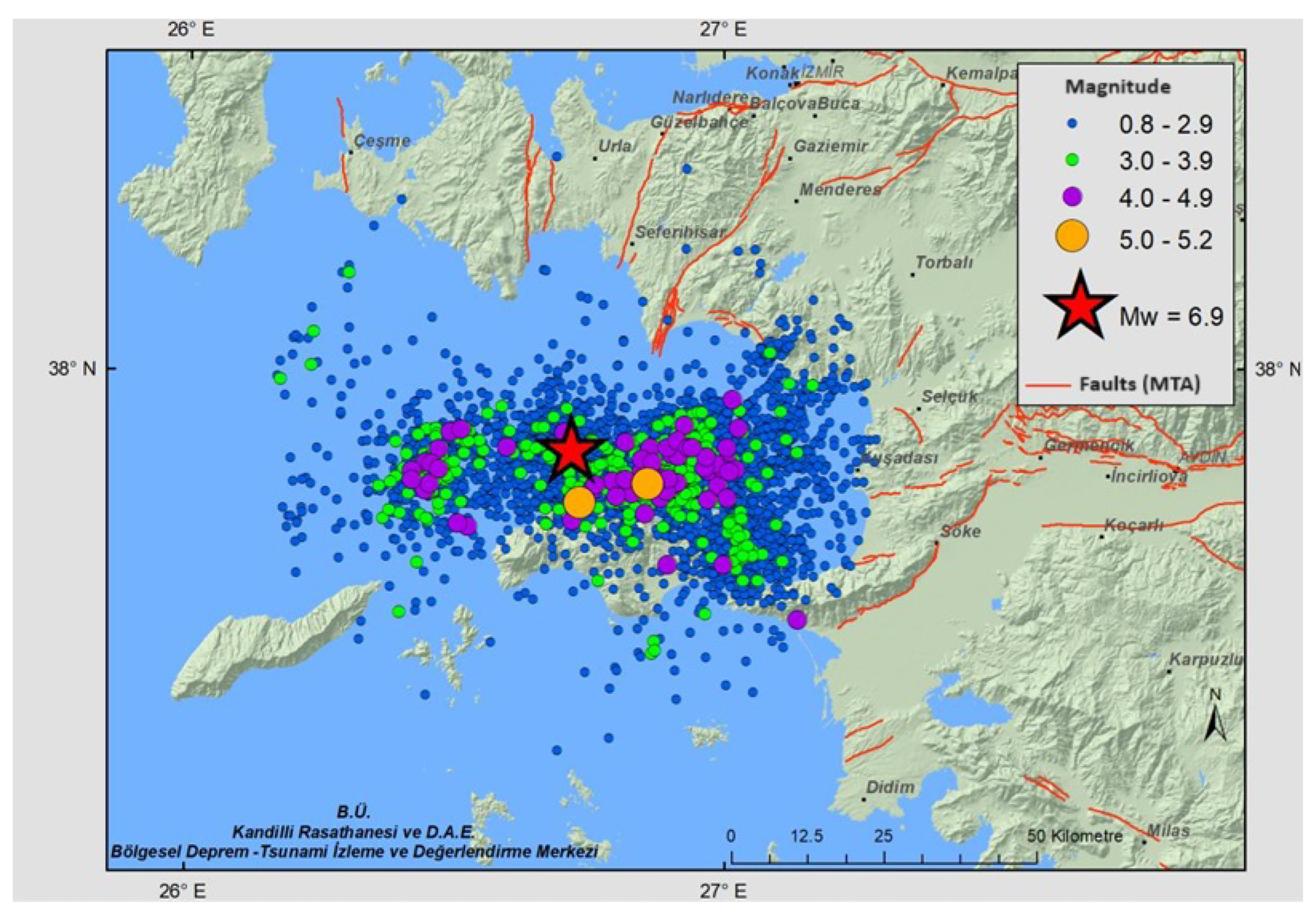
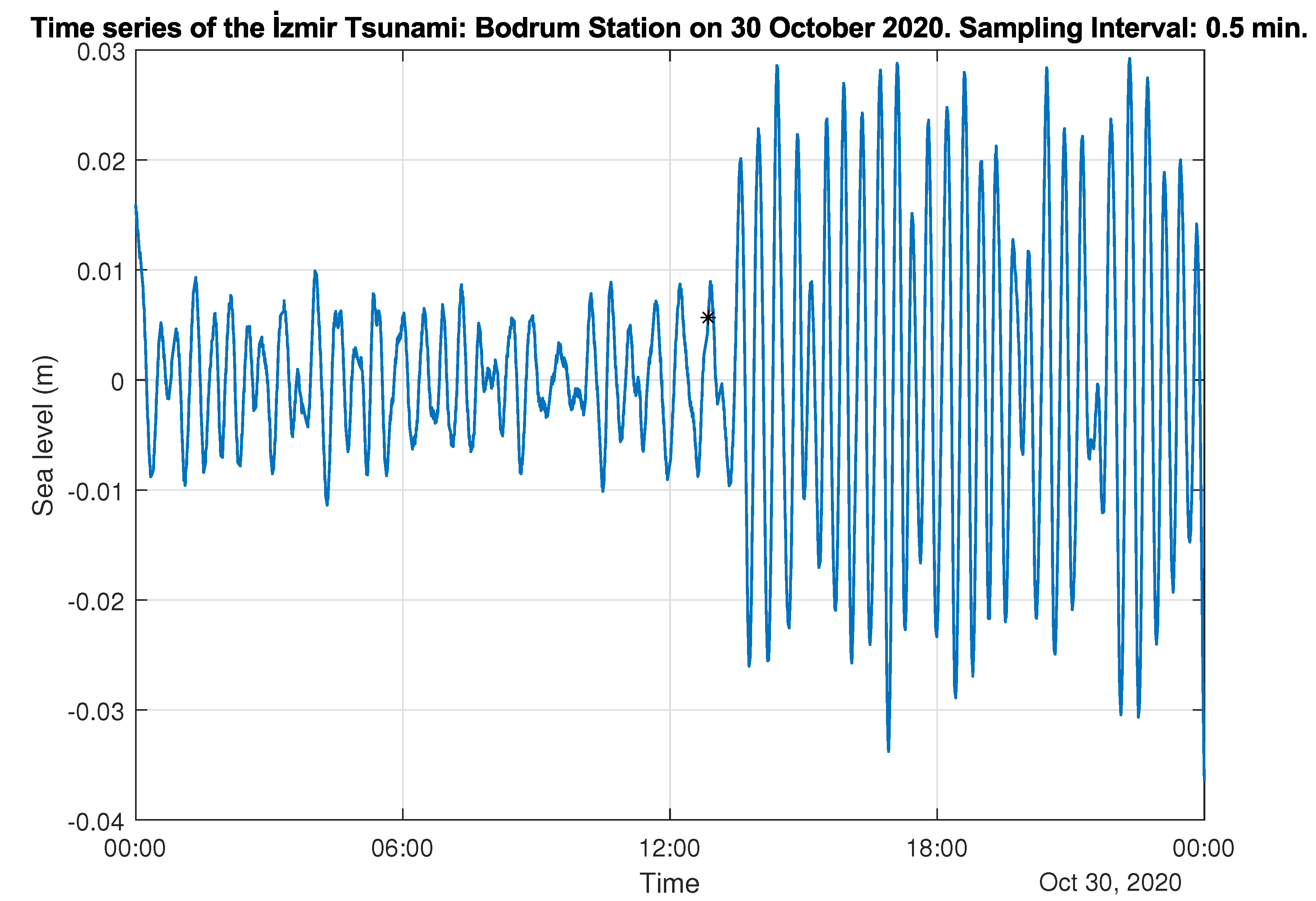
2.1. Study Area
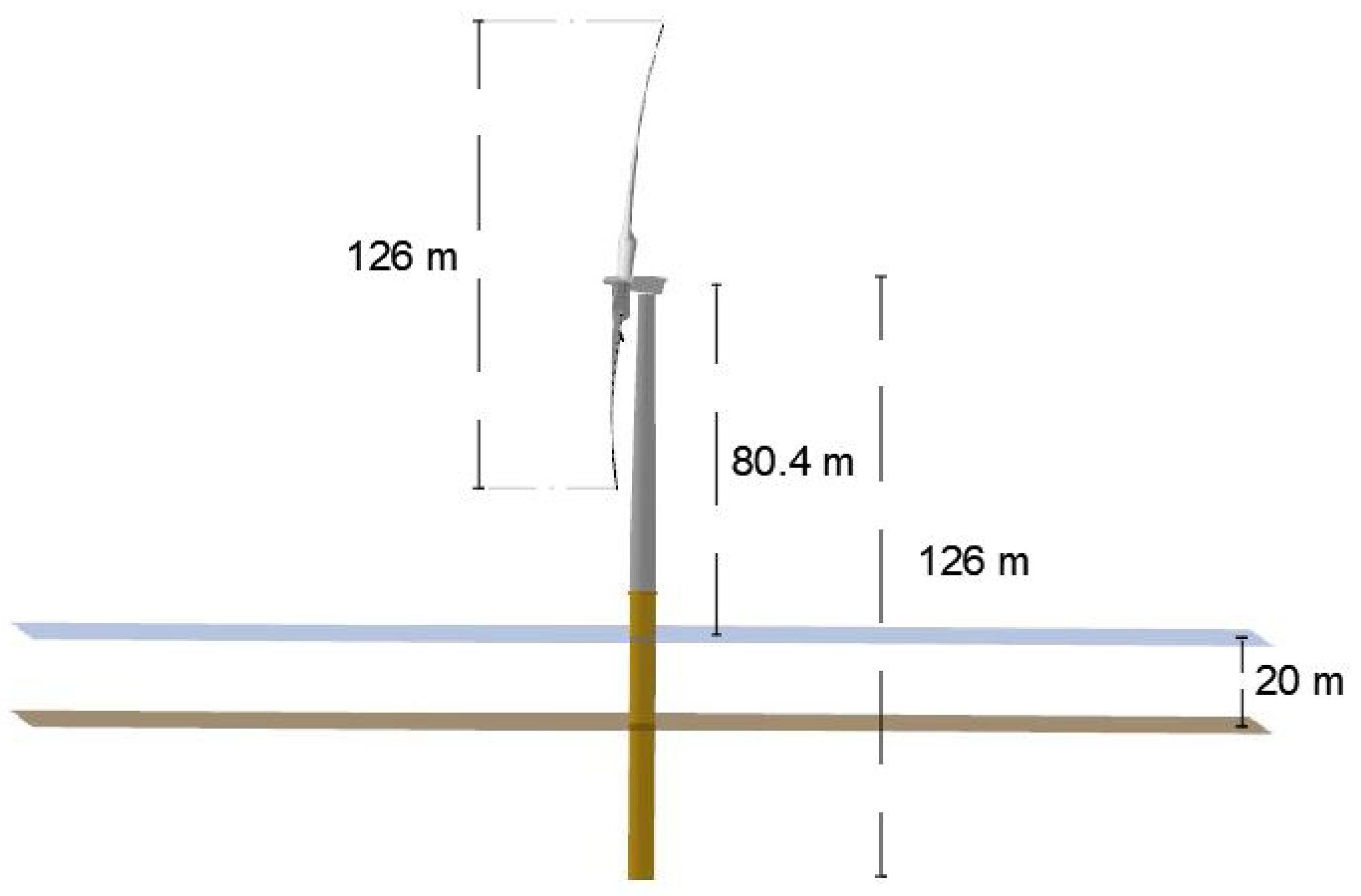
2.2. Offshore Wind Turbine
2.3. Aerodynamics of Wind Turbine
2.3.1. Blade Element Momentum Theory
2.3.2. Unsteady Blade Element Momentum
2.4. Hydrodynamics of Wind Turbine
2.4.1. Potential Flow and Boundary Conditions
2.4.2. Morison Equation
3. Results and Discussion
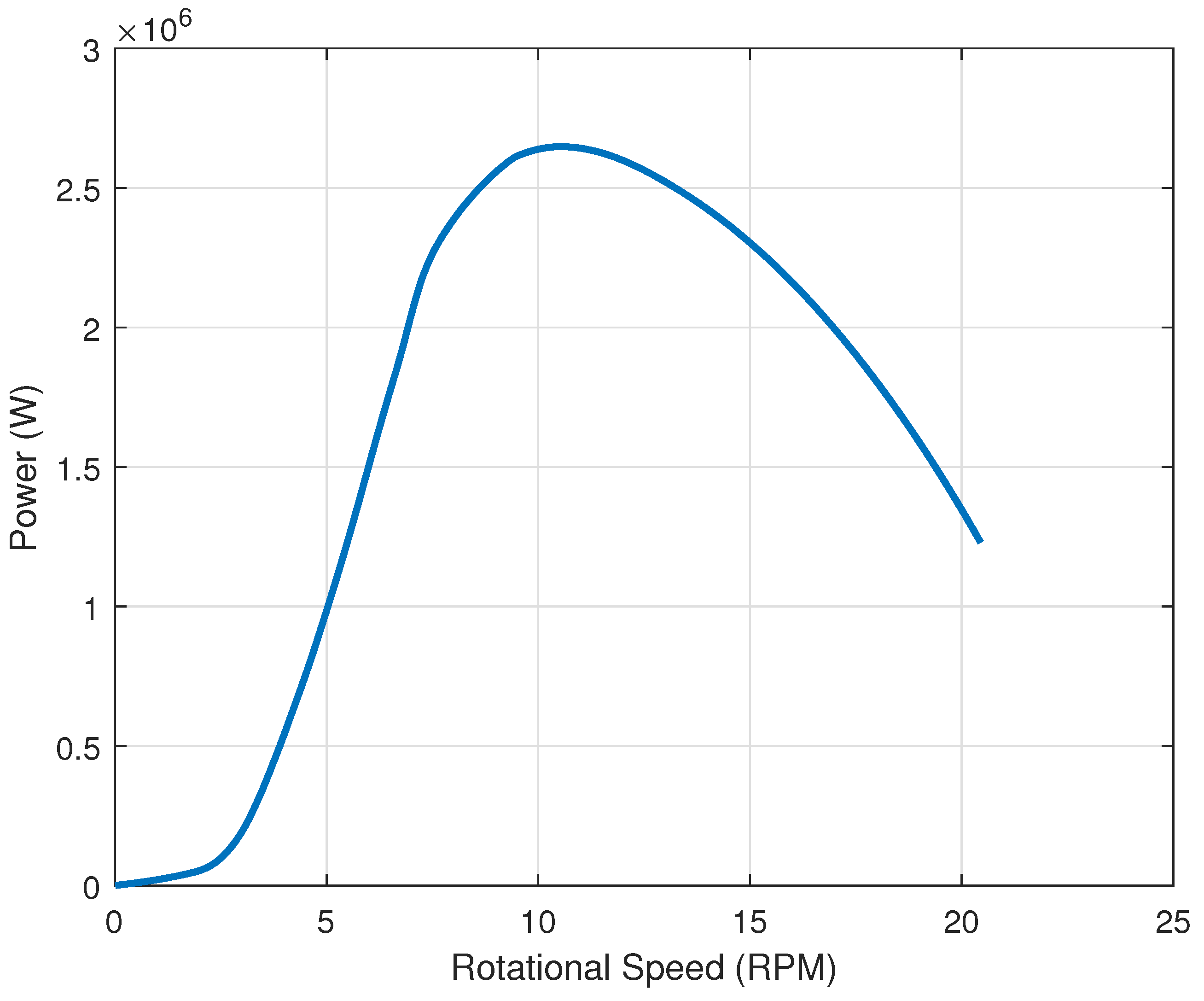
3.1. Validation of BEM Analysis
3.2. Hydrodynamic and Aerodynamic and Analysis of NREL 5 MW Monopile Wind Turbine Under the Effect of Tsunami Wave
4. Conclusions
Author Contributions
Funding
Data Availability Statement
Conflicts of Interest
Abbreviations
| BEM | Blade Element Momentum |
| CFD | Computational Fluid Dynamics |
| FFT | Fast Fourier Transform |
| FOWT | Floating Offshore Wind Turbine |
| GMT | Greenwich Mean Time |
| IFFT | Inverse Fast Fourier Transform |
| KOERI | Boğaziçi University Kandilli Observatory and Earthquake Research Institute |
| LSTM | Long-short term memory |
| NREL | National Renewable Energy Laboratory |
| UBEM | Unsteady Blade Element Momentum |
| UNESCO | United Nations Educational, Scientific and Cultural Organization |
| UTC | Universal Time Coordinated |
References
- Cheng, P.; Huang, Y.; Wan, D. A numerical model for fully coupled aero-hydrodynamic analysis of floating offshore wind turbine. Ocean Eng. 2019, 173, 183–196. [Google Scholar] [CrossRef]
- Tran, T.T.; Kim, D.H. A CFD study of coupled aerodynamic-hydrodynamic loads on a semisubmersible floating offshore wind turbine. Wind Energy 2018, 21, 70–85. [Google Scholar] [CrossRef]
- Shi, W.; Zhang, L.; Karimirad, M.; Michailides, C.; Jiang, Z.; Li, X. Combined effects of aerodynamic and second-order hydrodynamic loads for floating wind turbines at different water depths. Appl. Ocean Res. 2023, 130, 103416. [Google Scholar] [CrossRef]
- Xu, S.; Zhuang, T.; Zhao, W.; Wan, D. Numerical investigation of aerodynamic responses and wake characteristics of a floating offshore wind turbine under atmospheric boundary layer inflows. Ocean Eng. 2023, 279, 114527. [Google Scholar] [CrossRef]
- Bayati, I.; Jonkman, J.; Robertson, A.; Platt, A. The effects of second-order hydrodynamics on a semisubmersible floating offshore wind turbine. IOP Conf. Ser. Mater. Sci. Eng. 2014, 524, 012094. [Google Scholar] [CrossRef]
- Ren, N.; Ma, Z.; Fan, T.; Zhai, G.; Ou, J. Experimental and numerical study of hydrodynamic responses of a new combined monopile wind turbine and a heave-type wave energy converter under typical operational conditions. Ocean Eng. 2018, 159, 1–8. [Google Scholar] [CrossRef]
- Papi, F.; Bianchini, A.; Troise, G.; Mirra, G.; Marten, D.; Saverin, J.; de Luna, R.B.; Ducasse, M.; Honnet, J. FLOATECH D2.4 Full Report on the Estimated Reduction of Uncertainty in Comparison to the State-of-the-Art Codes OpenFAST and DeepLines Wind; Technical Report, FLOATECH Deliverable 2.4; FLOATECH: New Haven, CT, USA, 2022. [Google Scholar]
- Mahmuddin, F. Rotor blade performance analysis with blade element momentum theory. Energy Procedia 2017, 105, 1123–1129. [Google Scholar] [CrossRef]
- Alaskari, M.; Abdullah, O.; Majeed, M.H. Analysis of wind turbine using QBlade software. IOP Conf. Ser. Mater. Sci. Eng. 2019, 518, 032020. [Google Scholar] [CrossRef]
- Islam, M.R.; Bashar, L.B.; Rafi, N.S. Design and simulation of a small wind turbine blade with qblade and validation with MATLAB. In Proceedings of the 2019 4th International Conference on Electrical Information and Communication Technology (EICT), Khulna, Bangladesh, 20–22 December 2019; IEEE: Piscataway, NJ, USA, 2019; pp. 1–6. [Google Scholar]
- Koç, E.; Günel, O.; Yavuz, T. Comparison of Qblade and CFD results for small-scaled horizontal axis wind turbine analysis. In Proceedings of the 2016 IEEE International Conference on Renewable Energy Research and Applications (ICRERA), Birmingham, UK, 20–23 November 2016; IEEE: Piscataway, NJ, USA, 2016; pp. 204–209. [Google Scholar]
- Szczerba, Z.; Szczerba, P.; Szczerba, K.; Szumski, M.; Pytel, K. Wind tunnel experimental study on the efficiency of vertical-axis wind turbines via analysis of blade pitch angle influence. Energies 2023, 16, 4903. [Google Scholar] [CrossRef]
- Muhsen, H.; Al-Kouz, W.; Khan, W. Small wind turbine blade design and optimization. Symmetry 2019, 12, 18. [Google Scholar] [CrossRef]
- Bai, C.J.; Wang, W.C.; Chen, P.W.; Chong, W.T. System integration of the horizontal-axis wind turbine: The design of turbine blades with an axial-flux permanent magnet generator. Energies 2014, 7, 7773–7793. [Google Scholar] [CrossRef]
- Shen, X.; Avital, E.; Paul, G.; Rezaienia, M.A.; Wen, P.; Korakianitis, T. Experimental study of surface curvature effects on aerodynamic performance of a low Reynolds number airfoil for use in small wind turbines. J. Renew. Sustain. Energy 2016, 8, 053303. [Google Scholar] [CrossRef]
- Husaru, D.; Bârsănescu, P.; Zahariea, D. Effect of yaw angle on the global performances of horizontal axis wind turbine-QBlade simulation. IOP Conf. Ser. Mater. Sci. Eng. 2019, 595, 012047. [Google Scholar] [CrossRef]
- Chaudhary, M.K.; Prakash, S.; Kushawaha, S.; Gupta, L.; Humbre, P.; Patil, A.N. Numerical and experimental analysis of a small horizontal axis wind turbine rotors. AIP Conf. Proc. 2020, 2311, 030002. [Google Scholar]
- Barber, S.; Nordborg, H. Comparison of simulations and wind tunnel measurements for the improvement of design tools for vertical axis wind turbines. J. Phys. Conf. Ser. 2018, 1102, 012002. [Google Scholar] [CrossRef]
- Matsunobu, T.; Inoue, S.; Tsuji, Y.; Yoshida, K.; Komatsuzaki, M. Seismic design of offshore wind turbine withstands great east Japan earthquake and tsunami. J. Energy Power Eng. 2014, 8, 2039–2044. [Google Scholar]
- Min, E.H.; Kim, S.J.; Lee, I.; Kim, M.; Koo, B. Dynamic response of moored 15MW floating offshore wind turbine in tsunami-waves. In Proceedings of the OCEANS 2024-Halifax, Halifax, NS, Canada, 23–26 September 2024; IEEE: Piscataway, NJ, USA, 2024; pp. 1–5. [Google Scholar]
- Zhang, L.; Ji, B.; Liu, H.; Wang, J.; Xu, D.; Xu, H. Impact Risk Assessment of Gravity-Based Foundation of Offshore Wind Turbine Under Tsunamis. J. Earthq. Tsunami 2025, 19, 2450030. [Google Scholar] [CrossRef]
- Alan, A.R.; Bayındır, C.; Ozaydin, F.; Altintas, A.A. The predictability of the 30 October 2020 İzmir-Samos tsunami hydrodynamics and enhancement of its early warning time by LSTM deep learning network. Water 2025, 15, 4195. [Google Scholar] [CrossRef]
- KOERI. Boğaziçi University Kandilli Observatory and Earthquake Research Institute, Regional Earthquake-Tsunami Monitoring and Evaluation Center 30 October 2020 Aegean Sea Earthquake Press Release. 2020. Available online: http://www.koeri.boun.edu.tr/sismo/2/wp-content/uploads/2020/10/20201030_izmir_V1.pdf (accessed on 10 October 2023).
- Kiratzi, A.; Papazachos, C.; Özacar, A.; Pinar, A.; Kkallas, C.; Sopaci, E. Characteristics of the 2020 Samos earthquake (Aegean Sea) using seismic data. Bull. Earthq. Eng. 2022, 20, 7713–7735. [Google Scholar] [CrossRef]
- Ren, C.; Yue, H.; Cao, B.; Zhu, Y.; Wang, T.; An, C.; Ge, Z.; Li, Z. Rupture process of the 2020 Mw = 6.9 Samos, Greece earthquake on a segmented fault system constrained from seismic, geodetic, and tsunami observations. Tectonophysics 2022, 839, 229497. [Google Scholar] [CrossRef]
- UNESCO/IOC. UNESCO Intergovernmental Oceanographic Commission Sea Level Station Monitoring Facility. 2020. Available online: https://www.ioc-sealevelmonitoring.org/station.php?code=stationcode (accessed on 10 October 2023).
- Jonkman, J.; Butterfield, S.; Musial, W.; Scott, G. Definition of a 5-MW Reference Wind Turbine for Offshore System Development; Technical Report; National Renewable Energy Lab (NREL): Golden, CO, USA, 2009. [Google Scholar]
- QBlade Developers. QBlade Downloads Page. 2025. Available online: https://qblade.org/downloads/#Changelog (accessed on 22 March 2025).
- QBlade Documentation. Blade Element Momentum (BEM) Theory in QBlade. 2025. Available online: https://docs.qblade.org/src/theory/aerodynamics/bem/bem.html (accessed on 22 March 2025).
- Branlard, E. Wind Turbine Aerodynamics and Vorticity-Based Methods: Fundamentals and Recent Applications; Springer: Cham, Switzerland, 2017. [Google Scholar]
- GIanert, H. Airplane Propellers; Springer: Berlin/Heidelberg, Germany, 1935. [Google Scholar]
- QBlade Documentation. Aerodynamics Theory in QBlade. 2024. Available online: https://docs.qblade.org/index.html (accessed on 22 March 2025).
- Silva, C.T.; Donadon, M.V. Unsteady blade element-momentum method including returning wake effects. J. Aerosp. Technol. Manag. 2013, 5, 27–42. [Google Scholar] [CrossRef]
- Henriksen, L.C.; Hansen, M.H.; Poulsen, N.K. A simplified dynamic inflow model and its effect on the performance of free mean wind speed estimation. Wind Energy 2013, 16, 1213–1224. [Google Scholar] [CrossRef]
- QBlade Documentation. Linear Potential Flow Theory (LPFT) in QBlade. 2024. Available online: https://docs.qblade.org/src/theory/hydrodynamics/lpft/lpft.html (accessed on 22 March 2025).
- Newman, J.N. Marine Hydrodynamics; The MIT Press: Cambridge, MA, USA, 2018. [Google Scholar]
- Cummins, W. The impulse response functions snd ship motion. Schiffstechnik 1962, 9, 101–109. [Google Scholar]
- Zhao, W.; Cheng, P.; Wan, D. Numerical computation of aerodynamic performances of NREL offshore 5-MW baseline wind turbine. In Proceedings of the ISOPE Pacific/Asia Offshore Mechanics Symposium, Shanghai, China, 12–16 October 2014; ISOPE: Mountain View, CA, USA, 2014; p. ISOPE–P. [Google Scholar]
- Zhang, Q.; Wang, X. Numerical investigation of aerodynamic performances for NREL 5-MW offshore wind turbine. Wind 2023, 3, 191–212. [Google Scholar] [CrossRef]
- Durand, W.F.; Glauert, H. Airplane Propeller: Aerodynamic Theory: A General Review of Progress Under a Grant of the Guggenheim Fund for the Promotion of Aeronauticss; Springer: Berlin/Heidelberg, Germany, 1935. [Google Scholar]
- Bayındır, C.; Namlı, B. Efficient sensing of Von Karman vortices using compressive sensing. Comput. Fluids 2021, 226, 104975. [Google Scholar] [CrossRef]


Disclaimer/Publisher’s Note: The statements, opinions and data contained in all publications are solely those of the individual author(s) and contributor(s) and not of MDPI and/or the editor(s). MDPI and/or the editor(s) disclaim responsibility for any injury to people or property resulting from any ideas, methods, instructions or products referred to in the content. |
© 2025 by the authors. Licensee MDPI, Basel, Switzerland. This article is an open access article distributed under the terms and conditions of the Creative Commons Attribution (CC BY) license (https://creativecommons.org/licenses/by/4.0/).
Share and Cite
Namlı, B.; Bayındır, C.; Ozaydin, F. Hydrodynamic Analysis of a NREL 5 MW Monopile Wind Turbine Under the Effect of the 30 October 2020 İzmir-Samos Tsunami. J. Mar. Sci. Eng. 2025, 13, 857. https://doi.org/10.3390/jmse13050857
Namlı B, Bayındır C, Ozaydin F. Hydrodynamic Analysis of a NREL 5 MW Monopile Wind Turbine Under the Effect of the 30 October 2020 İzmir-Samos Tsunami. Journal of Marine Science and Engineering. 2025; 13(5):857. https://doi.org/10.3390/jmse13050857
Chicago/Turabian StyleNamlı, Barış, Cihan Bayındır, and Fatih Ozaydin. 2025. "Hydrodynamic Analysis of a NREL 5 MW Monopile Wind Turbine Under the Effect of the 30 October 2020 İzmir-Samos Tsunami" Journal of Marine Science and Engineering 13, no. 5: 857. https://doi.org/10.3390/jmse13050857
APA StyleNamlı, B., Bayındır, C., & Ozaydin, F. (2025). Hydrodynamic Analysis of a NREL 5 MW Monopile Wind Turbine Under the Effect of the 30 October 2020 İzmir-Samos Tsunami. Journal of Marine Science and Engineering, 13(5), 857. https://doi.org/10.3390/jmse13050857