Article

Hydrodynamic Modeling of a Reef-Fringed Pocket Beach Using a Phase-Resolved Non-Hydrostatic Model

1
School of Earth Sciences, The University of Western Australia, Crawley 6009, Australia
2
ARC Centre of Excellence for Coral Reef Studies, Crawley 6009, Australia
3
Marine Research Center, Ministry of Marine Affairs and Fisheries, Jakarta 14430, Indonesia
4
Oceans Graduate School, The University of Western Australia Oceans Institute, Crawley 6009, Australia
*
Author to whom correspondence should be addressed.
J. Mar. Sci. Eng. 2020, 8(11), 877; https://doi.org/10.3390/jmse8110877
Submission received: 31 August 2020 / Revised: 13 October 2020 / Accepted: 28 October 2020 / Published: 4 November 2020
(This article belongs to the Special Issue Observation, Analysis, and Modeling of Nearshore Dynamics)

Abstract

:
The non-hydrostatic wave-flow model SWASH was used to investigate the hydrodynamic processes at a reef fringed pocket beach in southwestern Australia (Gnarabup Beach). Gnarabup Beach is a ~1.5 km long beach with highly variable bathymetry that is bounded by rocky headlands. The site is also exposed to large waves from the Southern Ocean. The model performance was evaluated using observations collected during a field program measuring waves, currents and water levels between June and July 2017. Modeled sea-swell wave heights (periods 5–25 s), infragravity wave heights (periods 25–600 s), and wave-induced setup exhibited moderate to good agreement with the observations throughout the model domain. The mean currents, which were highly-spatially variable across the study site, were less accurately predicted at most sites. Model agreement with the observations tended to be the worst in the areas with the most uncertain bathymetry (i.e., areas where high resolution survey data was not available). The nearshore sea-swell wave heights, infragravity wave heights and setup were strongly modulated by the offshore waves. The headlands and offshore reefs also had a strong impact on the hydrodynamics within the lagoon (bordered by the reefs) by dissipating much of the offshore sea-swell wave energy and modifying the pattern of the nearshore flows (magnitude and direction). Wave breaking on the reef platforms drove strong onshore directed mean currents over the reefs, resulting in off-shore flow through channels between the reefs and headlands where water exchanges from the lagoon to ocean. Our results demonstrate that the SWASH model is able to produce realistic predictions of the hydrodynamic processes within bathymetrically-complex nearshore systems.

1. Introduction

Reefs (including coral and rocky) are common features in nearshore environments worldwide. The physical mechanism underlying the hydrodynamic process on reef beaches can be similar to sandy beaches, however the presence of the reefs introduces key differences. For example, infragravity (IG) waves (with periods of 25–600 s) have been shown to often account for a considerable portion of the total wave energy, e.g., [1,2] and thus are key to developing an understanding of the hydrodynamic processes. Reefs are often also detached from the shoreline and/or are discontinuous in the alongshore thus introducing two-dimensionality in the waves and the resulting wave-driven mean currents. This two-dimensionality is often accompanied by large bottom roughness and steep slopes formed by the reef morphology. While an increasing body of research has been conducted on the hydrodynamics of coral reefs (e.g., see [3] and [4] for reviews), less research has been conducted at sites that include smaller scale (O(100 m)) reef structures that are particularly common along temperate rocky coastlines, e.g., [5].
Numerical models used to study reef hydrodynamics have been based on phase-averaged and phase-resolving wave models that were generally originally developed for sandy beaches with mild-slope assumptions and smaller bottom roughness features [6,7]. Phase-averaged wave models attempt to model the statistical evolution of the sea-swell portion of the wave spectrum (SS, periods of 5–25 s) based on linear wave theory with empirical parameterizations to describe nonlinear physics (e.g., wave breaking and bottom friction dissipation). For phase-averaged models to simulate wave-driven mean flows, they must be coupled to a separate circulation model. Phase-averaged models (in nearly all cases) also do not attempt to resolve the low-frequency IG portion of the wave spectrum that results from nonlinear energy transfers. To incorporate the dynamics of IG waves, ‘surf-beat’ models (e.g., XBeach, Roelvink, et al. [8]) resolve the IG motions at wave-group scales. They have increasingly been used to understand hydrodynamics in reef environments, e.g., [9]. However, while ‘surfbeat’ models account for energy in the IG portion of the frequency spectrum, they do not account for the individual shape of sea-swell waves.
Phase-resolving models (non-hydrostatic or Boussineq-type) models have the advantage that by resolving the individual waves at the scale of SS waves, they natively account for dispersion and energy transfers across the spectrum and can thus be used for studies of wave breaking and runup that are not possible with phase-averaged wave models [10,11]. While phase-resolving models can also capture aspects of the breaking of individual waves, details of the breaking process (e.g., involving the overturning of the free surface) are still mostly parameterized—for example, see [12,13]. While phase-resolving models generally benefit from directly incorporating more of the physics, the main disadvantage is the additional (and often significant) increase in computational cost. Therefore, for relatively large field-scale simulations of reef hydrodynamics (e.g., scales of kilometers or larger), phase-averaged models have been much more commonly applied.
Continuous advances in computational performance, especially over the past decade, have increasingly enabled the application of surf-beat and phase-resolving models to conduct detailed investigations of nearshore hydrodynamics at field scales, including for reef environments. For example, [9] successfully used the surf-beat version of XBeach with calibrated bottom friction coefficients to model the spatial variability of IG wave dynamics at Ningaloo Reef, Western Australia. Some studies on reef environments (not limited to field scales) have also applied the surf-beat approach with promising results, e.g., [14,15,16]. Most phase resolving models are categorized based on their underlying equations. Non-hydrostatic models solve the non-linear shallow water equations with the addition of the non-hydrostatic pressure to account for wave propagation and frequency-dependent dispersion across sloping bottoms, e.g., [17,18]; whereas, Boussinesq-type wave models solve weakly dispersive and (weakly) nonlinear forms of these basic equations, e.g., [13,19,20]. Non-hydrostatic and Boussinesq models have demonstrated skill in predicting wave transformation in reef environments in several studies [21,22,23,24].
Despite the increasing use of phase-resolving models in reef environments, most applications have been limited to sites that do not include considerable two-dimensionality in the cross- and alongshore directions. Here we aim to assess the suitability of the non-hydrostatic wave model SWASH [18] to simulate hydrodynamic processes at a rocky reef-fringed pocket beach (Gnarabup Beach) in the southwest of Western Australia (Figure 1). SWASH has previously been used to model open coast sandy beaches, e.g., [25,26] and reef environments with rough bottom profiles, e.g., [27,28]. However, compared to the sites where SWASH (and other analogous phase-resolving models) have previously been applied, Gnarabup Beach tends to be more three-dimensionally complex due to the large spatial gradients in bathymetry combined with frequent exposure to large waves (including exceeding 5 m during this study). The site features two rocky reefs that front a pocket beach bound by rocky headlands (Figure 1). The model is compared to an extensive set of in situ observations. The model is then used to understand the wave and circulation dynamics along the beach during different wave and water level conditions.

2. Methods

2.1. Study Site and Field Observations

The study focused on Gnarabup Beach in the southwest of Western Australia (Figure 1) [29]. The beach is a 1.5 km long pocket beach that is fronted by two limestone reefs located ~600 m offshore. The reefs become partially exposed at low water levels (see Figure 1a), forming a semi-protected lagoon (hereinafter referred to as ‘lagoon’ for simplicity). The area behind the reefs has depths ranging from 2 to 5 m with the seabed consisting of a mix of medium to coarse carbonate sands, seagrass, and scattered limestone rocks. With exposure to the Southern Ocean, the offshore wave conditions consist of mostly swell, with offshore significant wave heights averaging ~2–3 m but can reach ~8 m during storm conditions [29]. The tides at the site are micro-tidal with average and maximum tidal range during the study period of 0.36 m and ~1.25 m, respectively.
A 4-week field study was conducted in June–July 2017 to quantify the transformation of waves from offshore to the beach and to record the circulation dynamics within the lagoon as reported in [29]. During the study, an array of 22 instruments were deployed offshore and inside the lagoon (Figure 1a). Two Nortek AWACs were placed outside the lagoon at ~19 and ~21 m depth directly offshore of each reef. Inside the reef system, 8 current meters (4 Nortek Aquadopp Profilers, 2 Nortek Vectors, and 2 Teledyne RDI Acoustic Doppler Current Profilers (ADCP) and 12 RBRsolo pressure sensors were situated in cross shore and alongshore arrays to record the waves, water levels and currents (Figure 1a, Table 1).
Directional wave spectra from the offshore AWAC sensors (S0 and C0) were computed with the Maximum Likelihood Method using the Nortek Storm software. Inside the lagoon, wave spectra (converting from the pressure spectra using linear wave theory) were calculated at each sensor location from hourly records of pressure collected at 1 or 2 Hz (3600 or 7200 samples, see Table 1) using Welch’s averaged periodogram method with a Hamming window of 50% overlap to reduce spectral leakage. The wave spectra were integrated within the sea-swell band with periods of 5–25 s (0.2–0.04 Hz) and infragravity (IG) with periods 25–600 s (0.0017–0.04 Hz) to compute significant wave heights within each band. The observed wave setup for the lagoon sensors was estimated from depth difference between the sensors located at the reef and offshore [29,30,31],
η ¯ = h ¯ ( h 0 ¯ + Δ h ) ,
where η ¯ is the wave setup at the lagoon sites; h ¯ and h ¯ 0 are the mean depth obtained from the recorded pressure time series at the lagoon site and at the offshore AWAC-C0 respectively, with the overbars indicating hourly averaging; and Δ h is the difference in elevation between the offshore sensor and the lagoon sensors. In this study, we neglected setup calculations at sites C1, C4 and S7, due to evidence of some drift in the setup estimates, possibly caused by either sensor drift or the instruments settling during the deployment.
The velocity profiles recorded by the acoustic current profilers were depth-averaged and then time-averaged (hourly). Also, we assumed the velocity information from the Nortek Vectors, which provided point velocity measurements just above the sensor located ~1 m above the bottom, to be comparable to depth averaged currents due to the relatively shallow depths (2.5–3 m, see Table 1). In this study, we focused on swell events (Tp > ~10 s, see Figure 2a) that occurred between 30 June to 3 July 2017 during which time the significant wave heights Hs recorded by AWACs ranged between 2.4 and 5.0 m (mean Hs 3.4 m, Figure 2a) and the hourly-mean water levels ranged from −0.15 to 0.19 m.

2.2. Numerical Model Description

SWASH numerically solves the Reynolds-averaged Navier-Stokes (RANS) equations for an incompressible fluid using second order finite difference scheme see [18], and references therein for details regarding the numerical implementation. For a three-dimensional flow field in the x (cross-shore), y (alongshore), z (vertical) directions, the governing equations of the model are:
ζ t + h U x + h V y = 0 ,
u t + u u x + v u y + w u z + g ζ x + q x = τ x x x + τ x y y + τ x z z ,
v t + v u x + v v y + w v z + g ζ y + q y = τ x y x + τ y y y + τ y z z ,
w t + w u x + w v y + w w z + g ζ z + q z = τ x z x + τ y z y + τ z z z ,
t is time, ζ is surface elevation measured from still water level d, h = ζ + d is the total water depth, u, v and w are the respective flow velocities in x-, y- and z- direction (with uppercase indicating depth-averaged velocities), g is the acceleration due to gravity, q is the non-hydrostatic pressure, and τ represents the turbulent stress terms.
At the bottom boundary, a quadratic friction law was included to model the stress induced by the seabed on the flow,
τ x z | z = d = c f U U + V h ,
in which cf is a dimensionless friction coefficient. For the turbulent stresses, separate eddy viscosities are used for horizontal and vertical mixing see [32] for details. The horizontal eddy viscosities in this work were computed from a Smagorisnky type formulation (with default parameters), and a constant vertical viscosity was used to enhance vertical mixing (1 × 10⁻⁵ m2/s).

2.3. Model Set-Up

SWASH was used to simulate the hydrodynamic conditions at Gnarabup Beach that occurred between 30 June and 3 July 2017 during 17 distinct hourly periods that were representative of the range of conditions. This approach was used to balance capturing a wide range of conditions with the highly-resolved (temporally and spatially) simulations over the large domain; continuous simulations over the entire period were not computationally feasible even using the high performance computing resources available. The numerical domain for Gnarabup Beach was constructed using a uniform rectangular computational grid with 3 m resolution in the cross-shore and 4 m in the alongshore, which was rotated 11.7° clockwise to align with the dominant direction of the coastline. This grid size was determined through a sensitivity analysis to grid resolution described in Appendix A. Bathymetry for the area was obtained through the Western Australia Department of Transport, with a majority of the area covered by a multi-beam survey collected in 2016 and some areas only covered by single beam survey from 1995 (refer to the spatial coverage of the available bathymetry in Figure 1b). Beach topography data were obtained from a backpack-based differential Global Positioning System (GPS) survey collected in February 2017 (see Figure 1b). While there was generally good bathymetry coverage over much of the study area, bathymetry data was not available for the very shallow areas over the reefs and headlands.
The depths in these areas were estimated at 0 m (relative to the Australian Height Datum, AHD, approximately mean sea level) for the areas that appeared exposed on aerial imagery collected during low water conditions. Adjacent areas were approximated with depths of −1 or −0.5 m based on the estimated submergence from the aerial imagery. The surveyed bathymetry and topography were linearly interpolated onto a 1 × 1 m grid, which was then used to generate the bathymetry within the model domain (Figure 1c). The offshore open boundary was located ~500 m offshore from the AWAC position, which includes a region with constant water depth of 25 m AHD (to ensure stable wave generation) and a gradual transition to the observed bathymetry.
Cyclic boundary conditions were applied along the lateral boundaries and were placed ~700 m away from the headlands that enclosed the pocket beach (see Figure 1c). With this approach, the model domain was continuous in the alongshore direction. To ensure that the bathymetry is repetitive without alongshore discontinuities, the domain was extended with a 300 m gradual transition between the northern and southern lateral boundary. The final model domain was 1.8 km by 3.0 km, resulting in spatial grid of 600 × 762 points with minimum and maximum bottom elevations of −25 m and 6.5 m, respectively.
At the offshore boundary, the 17 hourly scenarios were simulated that are part of a four day period (30 June to 3 July 2017) that include a wide range of offshore wave conditions (Hs from ~2–5 m) and water levels (Figure 2a–d). In this study we used hourly directional wave spectra estimated from the AWAC at C0, which was imposed uniformly along the offshore open boundary. The wave spectra measured at AWAC C0 were back-refracted and de-shoaled to the location of the wavemaker following the approach of [33]. Based on the directional wave spectra, short-crested sea states were generated in the model using a weakly reflective wavemaker including a second order correction to include bound infragravity waves [25].
The initial time step (∆t) within the computation was set to 0.025 s to satisfy 0.3 > Courant–Friedrichs–Lewy (CFL) < 0.8, with SWASH internally modifying the time step thereafter. Two equidistant vertical sigma (terrain-following) layers were used (i.e., each layer occupied 50% of the local water depth), which is sufficient to capture the dispersive characteristics of the considered sea states. We used the hydrostatic front approximation to capture the initiation of wave breaking [34] given the coarse vertical resolution.
For each of the 17 wave and water level conditions considered (Figure 2a–d), the model was run for 60 min plus an additional 30 min to allow for model spin-up. The spin-up period was defined based on examining the evolution of the integrated kinetic energy (KE), potential energy (PE) and enstrophy (Z, i.e., the integral of vorticity-Ω squared) over the model domain
K E = 0 L y 0 L x 1 2 h ( U 2 + V 2 ) d x d y ,
P E = 0 L y 0 L x 1 2 g ζ 2 d x d y ,
Z = 0 L y 0 L x 1 2 Ω 2 d x d y ,
where Ly and Lx are the cross-shore and long-shore lengths of model domain, respectively (Figure 3). The model was assumed to be in ‘steady state’ when these variables fluctuated about a steady mean see [33], for detailed explanation.
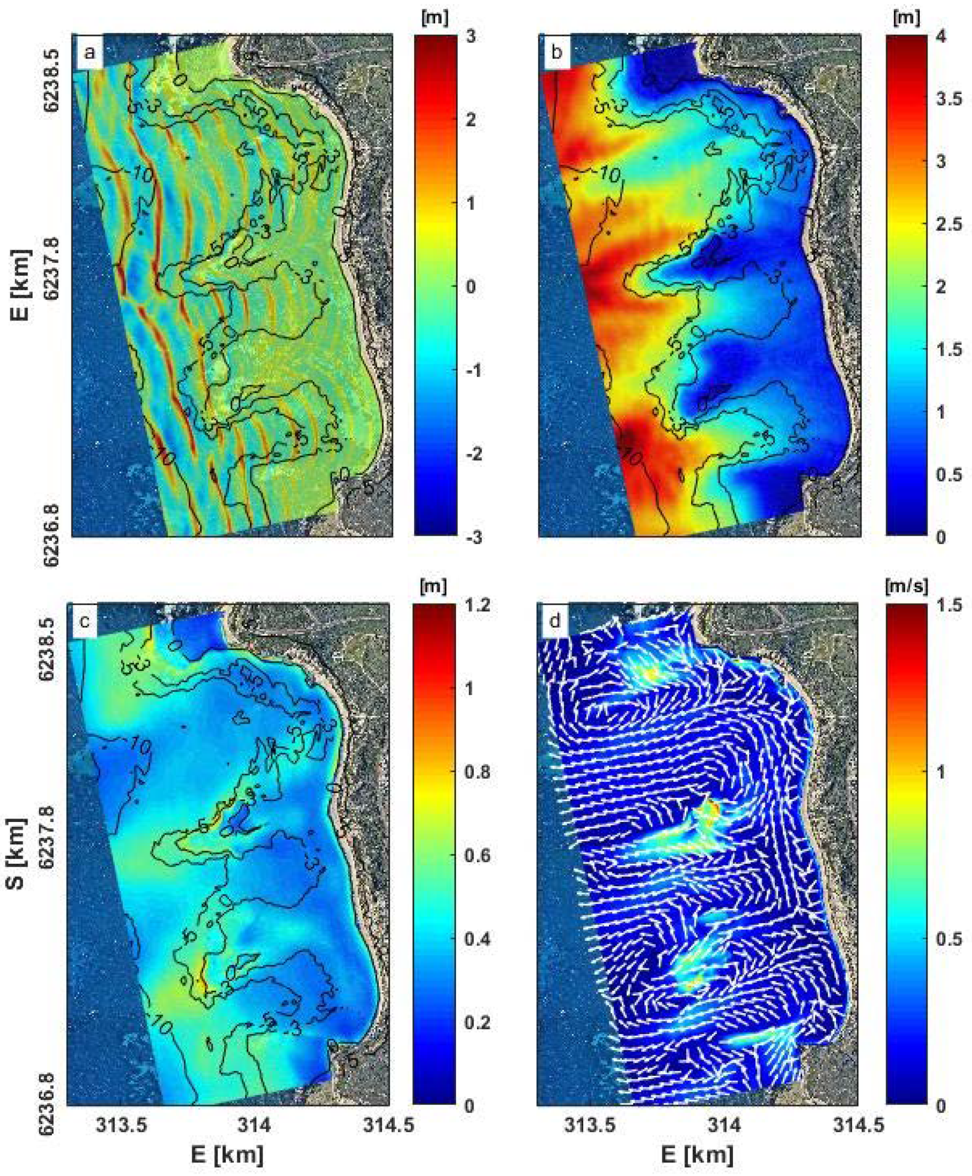
Output variables consisted of surface water level elevation and depth-averaged velocities (U and V), which were saved at 2 Hz over a 4 × 4 m grid. To minimize the overall computational time (including output generation), variables were only saved for an area of 1 km (cross-shore) × 1.8 km (alongshore) covering the area of interest (Figure 1c). Time series output were also saved at the location of each instrument within the domain (i.e., 22 instrument locations). The SS-IG waves and mean currents from the model were calculated using the same methods applied to the field data in Section 2.1. An example of the model output (instantaneous free surface elevations, SS and IG wave heights, and mean currents) are shown for one of the scenarios in Figure 4, with the estimated setup in Figure 5a.
Considering the spatial scale of the model, all simulations in this study were run on a supercomputer at the Pawsey Supercomputing Centre (Western Australia). Each one-hour simulation took about 20 h to complete using 48 cores.

2.4. Model Performance

Model performance was assessed against the observations at each of the 22 instrument sites using the Willmott Skill (WS), e.g., [35,36,37] which is computed as
W S = 1 | X m o d X o b s | 2 ( | X m o d X o b s ¯ | + | X o b s X o b s ¯ | ) 2 ,
where Xmod is a model prediction, Xobs is an observation, and overbars indicate averaging over the 17 scenarios. WS was computed at each site for various bulk wave and flow parameters for all 17 hourly scenarios (N = 17), with the over-bar indicating averaging over the 17 scenarios. Good model performance is considered when WS > 0.6, moderate performance when WS is 0.3 to 0.6, and poor when WS < 0.3. In addition to the WS, we also computed the root mean square error (RMSE) and the mean Bias to assess the model performance,
RMSE = i = 1 N ( X m o d X o b s ) 2 N ,
Bias = X m o d X o b s N ,

3. Results

3.1. Model Calibration

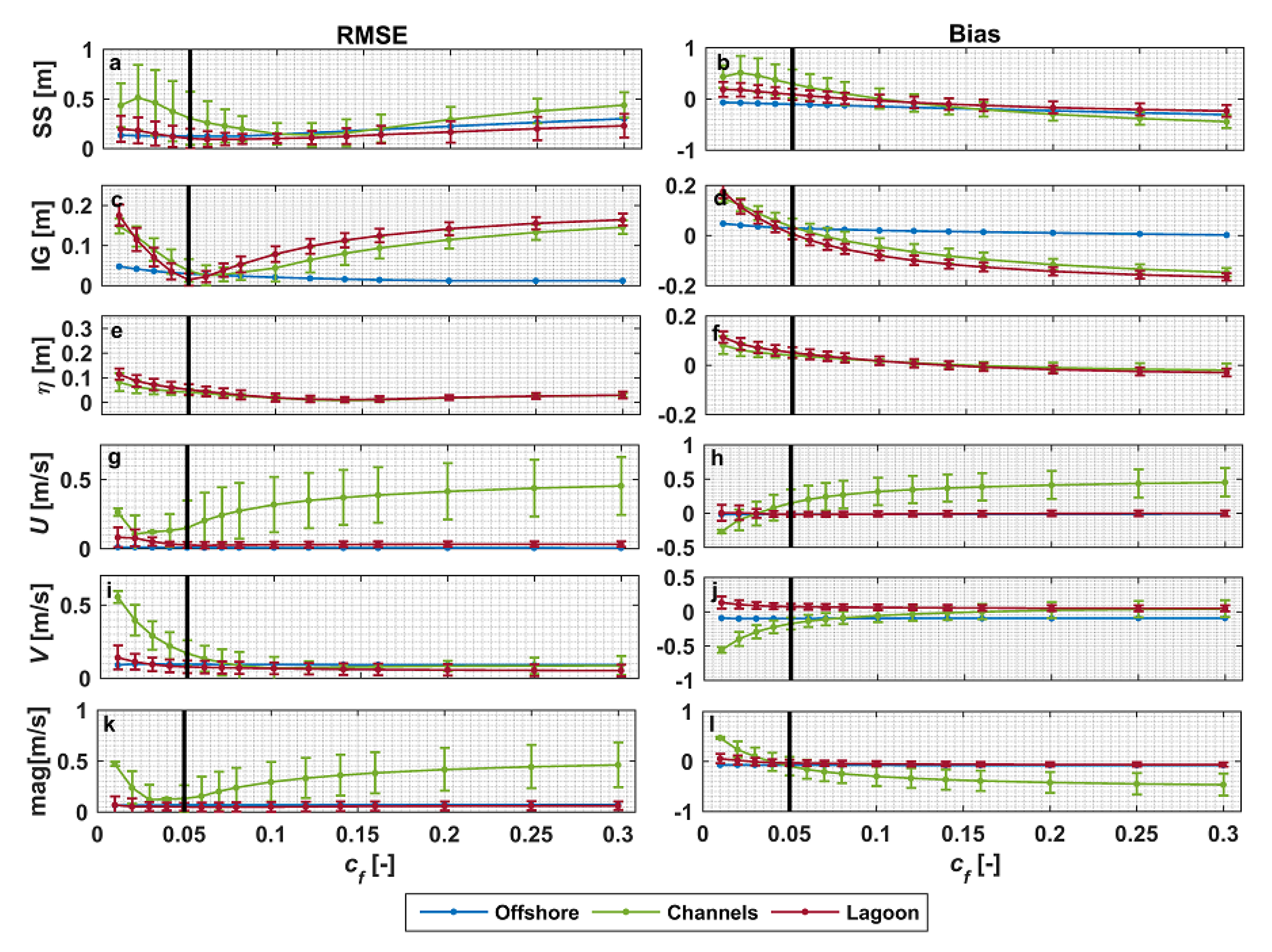
The model was calibrated for a single sea-state that represented relatively moderate conditions during the considered study period (Hs0 = 3.14 m with a Tp0 = 13.4 s at the offshore boundary). The calibration process focused on assessing the performance to variations in the empirical breaking parameter α [34] and bottom friction coefficient cf based on the comparison of the modeled and observed waves, mean water levels and currents at the 22 instrument sites. Changing the breaking parameter, α, over a range from 0.04 to 3 did not impact the model skill significantly (not shown), so we used the default value of α = 0.6 within SWASH. We next focused on the sensitivity of the model output to the uniform bottom friction coefficient (cf) to reproduce the hydrodynamic parameters within the model domain. While other drag formulations are available in SWASH (e.g., Manning), we adopted a constant friction coefficient that is commonly applied, including in reef environments, e.g., [27,38]. We varied the cf over a range from 0.01 to 0.08 across the domain in intervals of 0.01 for the first eight simulations and higher intervals 0.02 from 0.08 to 0.16 and 0.05 from 0.16 to 0.3. As we describe in Section 4, we also attempted a spatially-varying cf but did not find improved results for the cf values considered.
A summary of the RMSE and mean Bias between observation and model for SS and IG wave heights, setup η ¯ , and currents (magnitude, U and V components) for various bottom friction coefficients is shown in Figure 6, in which the sensors were grouped according to their location within the study site (offshore, channel and lagoon, Figure 1a). For each area, we present the average RMSE and Bias as well as the standard deviations across the sites within each grouping (with the exception of the offshore sites as there were only 2 sensors). At the offshore sites, the error and Bias (blue lines in Figure 6) were small (consistent with these sites being used to derive the boundary forcing). For shallower depths, i.e., in the channels (green lines) and the lagoon (red lines), as cf initially increased the results in general improved for wave heights, setup and currents, reached an optimum level of performance, and then often deteriorated for higher values of cf. Across the range of cf values considered, the overall model errors across all variables (SS and IG wave heights, setup, and currents) were lowest using a cf = 0.05 (Figure 6). The estimated cf value is within the range of other studies comparing from reef sites typically of the order 0.01–0.1, e.g., [9,39,40,41]. Thus, the cf value of 0.05 was subsequently applied to the full suite of scenarios.

3.2. Model Application

Following selection of an optimal bottom friction coefficient (cf) based on a typical (moderate) wave condition, we evaluated the model for all 17 scenarios over the 4-day period. Below, the predicted SS and IG wave heights, current velocities (U and V vectors, as well as the magnitude) and wave setup are compared against the observations. Similar to the analysis in the previous section, the results were grouped into 3 different zones of offshore, channels and lagoon. We also divided the lagoon into northern, central and southern areas based on the position of each instrument within the lagoon relative to the reefs (see yellow dashed lines in Figure 1a). The northern portion of the lagoon is deeper and relatively exposed to offshore waves (compared to the other parts) with scattered rocks near the shoreline (Figure 4). The central area is located behind two offshore reefs and influenced by strong currents due to wave breaking on the reefs. The southern area is the most protected part of the lagoon and typically has low SS wave energy and weak currents due to protection from the rocky headland.

3.2.1. Wave Height and Setup

Across the 17 scenarios, SWASH predictions showed the typical wave transformation processes within a coastal region. SS waves shoaled and subsequently broke on the reefs (Figure 4a,b). The dissipation of SS waves at the fringing reefs coincided with an increase in the IG wave heights (Figure 4c). Inside the lagoon, SS wave heights were significantly smaller than offshore, and the ratio between IG and SS waves was high (often greater than 0.6), especially near the shoreline, indicating the importance of IG waves in dictating shoreline water levels (not shown). Within the surf-zone (primarily over shallow reef areas), SWASH simulated breaking on the reefs and refraction/diffraction in their lee (Figure 4a). Mean water levels are lower in the offshore region where wave shoaling occurs (i.e., causing set down), and elevated due to wave setup on the reefs and near the shoreline (Figure 5) coinciding with regions of strong wave breaking.
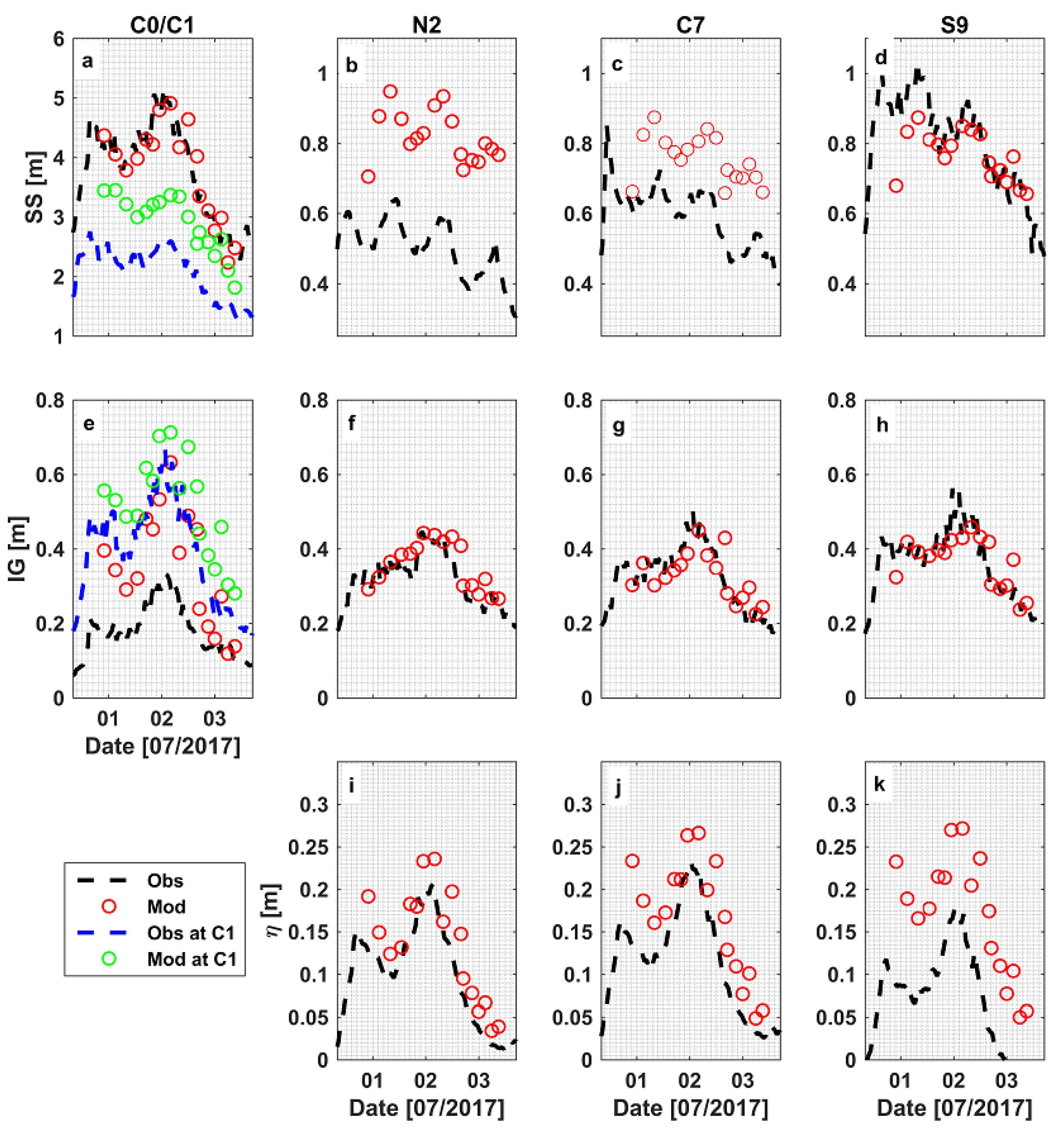
The performance of SWASH in predicting the observed waves and currents within each area of the study site are summarized in Figure 7 and Figure 8, and Table 2. The model performed well at reproducing the SS wave heights at the offshore site (WS ≥ 0.6, Bias < 5 cm) (Table 2). In the channels (Figure 7b), we noticed that for most of the 17 scenarios the model over predicted the SS wave heights (e.g., at site C1 see the blue dashed line and green dots in Figure 8a) and S1 (not shown), resulting in moderate skill at Central channel (WS = 0.55) but good skill at Southern channel (WS of 0.64) with a Bias at both locations of ~0.5 m. The SS wave heights shoreward of the southern channel (S2 and S3) tended to be better predicted (WS ≥ 0.6, Bias < ~5 cm) than those shoreward of the central channel (C2 and C3, with WS~0.3 and Bias > 0.2 m). Within the lagoon, SWASH predicted the SS wave heights in the area behind the southern offshore reefs with good accuracy (C8 and almost all sensors at the south part) with WS fluctuating from 0.64–0.85 and Biases ranging from 0.01–0.25 m. The individual lagoon sites with poor skill (WS below 0.3) mostly occurred at sites behind the northern reefs and the adjacent area (i.e., northern (N3) and central (C5–C6) parts), except at C4 that was located near the northern fringing reef where WS = 0.85. We note that regions with poor SS wave height model performance generally tended to be related to regions where there was the most uncertainty in the bathymetry; for example, in the northern portion of the lagoon the available bathymetry data was limited (see Figure 1b).
Scatter plots between the observed and modeled IG wave heights (Figure 7d–f) showed good agreement between the IG wave heights with WS ranging from 0.62 to 0.9 at all of the sites, with maximum Bias of ~0.1 m (Table 2). The RMSE of the modeled IG wave heights across three areas (northern, central and southern) were relatively small, ranging from 0.03 to 0.12 m for all sensors. At deeper areas, i.e., the AWAC sensors (C0 and S0), the predicted IG waves tended to be less accurate (over-predicted) during larger wave events (Figure 7d,e and Figure 8e), causing the overall WS score at these sensors to be around 0.6–0.7. Inside the lagoon, the IG wave predictions at all sensors showed WS ≥ 0.6 with Biases < 0.05 m. By comparing the IG waves at all sensors, we found that the IG waves showed less spatial variability across the sites (Figure 7f and Figure 8f–h), which indicates the IG waves were less impacted by the variable water depths in the lagoon.
Setup was, in general, well predicted with good WS at most sensors with slight over-prediction by the model compared to the observations, with a mean Bias of 0.05 m across all sites (Table 2). Despite the slight over-prediction of setup at all locations (Figure 7g,h), the model showed fairly consistent Bias and tracked the variations in the observed setup (Figure 8i–k). Further comparison between observation and model for each sensors showed that predicted setup in the northern and central areas (which are deeper and more exposed to offshore waves) was more accurate (WS > 0.8) than that in the more protected southern. This is in contrast with the SS wave heights for which the model performed better (on average) in the southern portion of the lagoon (Table 2).

3.2.2. Depth-Averaged Currents

We compared the modeled mean (hourly) currents from the 17 scenarios with the coinciding observations from the 10 sites that measured velocity located offshore (C0 and S0), in the channels (C1 and S1), as well as central and southern parts of the lagoon (C4, C6, S6, S7, S9, and S10) (Figure 1a). The observed currents across the 17 wave conditions showed a broad variability of flows within the study area, ranging from very weak currents inside the lagoon at the southern corner of the beach (S10) with average of 0.02 m/s (maximum of 0.03 m/s) to strong currents recorded in the channel sites (e.g., with average of 0.74 m/s, maximum of 1.02 m/s, at S1). Evaluation of the mean currents indicated that SWASH tended to under-predict the magnitudes (Figure 9a), except at C6 and S10 where the model over-predicted the current magnitudes. At all sites, we found that the Bias in the current magnitude was less than 0.1 m/s (Table 2). The model skills for each locations were moderate (0.3–0.6) for predicting currents at most sites, except at site C1 and S1 where there was good skill (WS ≥ 0.6) and one sites with poor skill at S7, as shown in Table 2.
The model also demonstrated moderate (at C0, S0, S6, and S10) and good skill (C6) in predicting current directions, even though the other sites exhibited poor skill (Table 2). Note that at some points, the discrepancies between observed and predicted current directions could be very large due to phase wrapping (e.g., >300°) resulting in poor skill, even though the comparison (Figure 9a) showed the directions did not differ too much. Hence, for these conditions, we considered the adjustment in direction by 360° to account for phase wrapping. At the channel sensors (C1 and S1, with poor WS at both sites), the modelled outflow had a more southerly direction compared to the observations. At the offshore sensors the model did not capture the observed northern flows, which is likely explained by larger scale flows that are not captured within the model. Despite these discrepancies, the model captured the overall flow patterns within the lagoon system, with weak flows in the lagoon and strong outflow through the channels (Figure 9a).
Figure 10 shows the comparison between the observed and modeled currents at the channels (C1 and S1) and inside the lagoon (C4, C6, S6, S7, S9, S10) for each of the 17 scenarios. This comparison shows that the model generally under-predicted the currents (Figure 10a,c). At the channel sensors, the model captured increasing current strengths for more energetic waves inside the channels (Figure 10a), although current directions were off by about 25° (Figure 10b). The current predictions were found to be in better agreement for larger off-shore wave conditions, with the incident wave directions were relatively constant across all wave conditions (the mean incident wave directions was 251 ± 3°, see Figure 2c).

3.3. General Circulation Dynamics

Despite the wave heights varying significantly over the study period (from 2.4 m to nearly 5 m), the observed wave directions were relatively consistent (247 to 255°; see Figure 2c) due to the persistent arrival of Southern Ocean swell along this portion of coastline. While the flow magnitudes varied, we observed similar circulation patterns over the 17 scenarios (Figure 9b). From the model results, we observed that wave breaking over the two reefs resulted in large setup on the reefs (up to 0.46 m) which drove onshore flows into the lagoon where setup was lower (Figure 5b). Towards the outer edges of the reefs, the modelled currents diverged directly into the channels resulting in lower mass flux into the shallower portions of the lagoon. Modeled currents along the shoreline (up to ~200 m offshore) were generally weak (averaging <0.06 m/s) in the central and southern portions of the lagoon as a result of the divergence of the flow from the reefs directly into the channels. In the deeper northern portion of the lagoon, the modeled currents were overall stronger along the beach, likely due to a combination of higher wave penetration into the lagoon, the larger gap between the northern reef and northern headland, as well as the increased depths compared to that of the central and the southern area (Figure 9b). Overall, the model revealed that current magnitudes near the shoreline were the largest in the northern portion of the lagoon and weakest in the central portion of the lagoon (Figure 9). The model also indicated some drainage of water from the central portion to the northern portion of the lagoon through the gap between the northern reef and shoreline (Figure 9b), associated with an alongshore pressure gradient (lower setup in northern part lagoon, Figure 5b). In the channels, the flow out of the lagoon was approximately proportional to the offshore wave height indicating the larger onshore mass flux into the lagoon and channels during larger wave conditions (Figure 11).
Despite the reefs not offering complete alongshore coverage (only occupying approximately one-third of the distance between the headlands) they still provide effective protection to the beach areas, especially in the southern and central portions of the lagoon. The model and observations show that the IG wave heights were more uniform across the lagoon (Figure 7f and [29]).

4. Discussion

In this study, we assessed the ability of SWASH to simulate the hydrodynamics of a complex nearshore site, with rocky reefs fronting a pocket beach bounded by rocky headlands. The model performance varied depending on the hydrodynamic processes that were simulated and spatial location within the study site. SWASH accurately predicted the IG waves (good skill, low RMSE, low Biases) at all the observed locations for 17 (hour) scenarios. It was found to reproduce the SS waves and setup well at majority of the sensors (see Table 2). When predicting the mean wave-driven currents, SWASH exhibited a wider range of skill (poor to good, WS 0.29 to 0.66), with relatively small RMS error (average of 0.09 m/s) and Bias (average of 0.07 m/s).
In our study, we identified some possible factors that potentially influenced the accuracy of the model. The specific locations where the SS waves and setup were most poorly predicted were mainly located on the northern part of the beach (see Table 2). The certainty of the bathymetry in the northern part of the beach is lower due to less survey coverage (see Figure 1b), with the depth in some areas (the shallow reefs) estimated from aerial images. In addition, this region features a number of small patch reefs (finer than grid cells) that are scattered within the domain (mainly at the northern part) could not be fully resolved in the model. These small reefs may cause SS waves to break in different areas than predicted in the model, thus likely contributing to the magnitude and direction of the resulting wave-driven flows, e.g., [42].
Other possible factors that potentially control the accuracy of modeled SS waves and setup is the type of computational grid used in the model. In this study, we used a structured rectilinear grid with a 3 (cross-) × 4 (along shore) m grid resolution. The main drawback of such a structured grid with a relatively coarse grid resolution is the limited flexibility to capture multiscale features of complex bathymetry [43]. As a result, the model likely did not capture all the details of the complex bathymetry of Gnarabup Beach. Furthermore, phase-resolving models like SWASH require fine resolutions to capture higher frequency waves, e.g., [1]. However, the use of finer grid sizes in this study, which greatly increases computational cost, did not significantly improve the results, as shown in Appendix A. This may reflect that to gain the benefits of higher resolution computations requires having sufficiently high-resolution bathymetry at these fine-scales, which was not available in this study. Presently SWASH also only allows uniform wave conditions (based on single directional spectrum) to be imposed on the offshore boundary. At the study site the AWACs offshore of each reef demonstrated slightly different wave conditions which could not be accounted for in the model (which was forced uniformly with the conditions observed at site C0).
When comparing the IG waves, the model exhibited stronger IG energy dissipation and weaker nearshore currents in shallower area (channels and lagoon) as the friction increased (Figure 6). The impact of various cf values to IG waves and mean currents has been identified in a number of reef hydrodynamic studies, e.g., [18,44,45]. In the present study, the best model performance for IG waves occurred when a uniform cf of 0.05 was applied across the entire domain (Figure 6). While SS waves, IG waves and setup were predicted with moderate to good skill, predictions of the mean wave-driven current were often less accurate. To investigate if predictions of the currents could be improved by using a spatially-uniform cf, we considered a simulation with a spatially variable cf to investigate its impact on the skill of the modeled currents (Figure 12a). The cf values of different locations within the domain were determined from visual estimation of aerial images. Sand was assigned cf = 0.002 based on [46], 0.02 for macro-algae vegetation, e.g., [47] and 0.05 for reef, e.g., [48]. We also identified some areas dominated by a mix of sand and vegetation, in which we defined the cf value of 0.01. The offshore forcing for this simulation was the moderate wave scenario with Hs = 3.4 m with a Tp = 13.4 s at AWAC C0. We compared the result of bulk waves at SS-IG bands, and mean currents (magnitudes and directions) at the 22 observed points, between the spatial cf and the uniform cf scenarios. At the offshore sites, there were effectively no differences between the compared variables of both scenarios, that also suggested the bottom friction has no impact on the waves and currents at deep water. However, in shallower depths (i.e., channels and lagoon), the spatially-varying cf simulations exhibit higher magnitudes of all modeled waves heights and currents than that of the uniform cf (Figure 12b–e). Overall, using the spatially variable cf resulted in worse model performance overall than using a spatially-uniform cf (Figure 12). While it is possible a different set of combinations of cf values may have resulted in better performance, the computational effort in obtaining the best possible combination of cf values would likely outweigh the incremental improvement in model performance.

5. Conclusions

This study evaluated the performance of the non-hydrostatic phase-resolving wave flow model SWASH that was applied to a reef fronted pocket beach with complex bathymetry. The SWASH model was applied to the study site and was used to assess the performance against the observed waves, setup, and currents at 22 instrument sites that spanned the offshore, channels, and lagoon over 4 days with persistent swell ranging in height from 2.4 to 5.0 m. Despite the complex bathymetry, the model generally reproduced the observed waves (both at SS and IG bands), setup and currents throughout the domain relatively well. The largest errors were associated with the mean currents. A spatially uniform friction coefficient, cf = 0.05, was found to best reproduce the observations, which is within the range of value found in many other reef studies. An attempt to use spatially variable friction coefficients representing the different bottom types found at the site (sand, aquatic vegetation, reef) did not improve results. In general, the model performed best in areas where the most accurate bathymetry was available (closest to survey lines), indicating that in complex nearshore reef environments such as at Gnarabup Beach, very high resolution bathymetry (order 1–10 m survey resolution) is necessary to properly resolve the nearshore hydrodynamics, independent of physical processes incorporated within the model.
The headlands and rocky reefs were found to have a major influence on the nearshore hydrodynamics of Gnarabup Beach. Even though the natural structures only partially protect the beach forming semi-protected lagoon, they effectively dissipate most of the offshore SS wave energy. Near the shoreline, and in particular the area behind the reefs, the wave motions were dominated by waves in the IG band that are less influenced by the variable water depth. Moreover, wave setup within the lagoon was strongly dependent on the offshore waves. Wave energy dissipation also generated strong onshore directed currents that flowed onshore over the reefs and circulated back offshore through the channels.

Author Contributions

Conceptualization, J.R., J.E.H., D.P.R. and R.J.L.; methodology, J.R., J.E.H., D.P.R. and R.J.L.; software, J.R. and D.P.R.; validation, J.R. and D.P.R.; formal analysis, J.R., J.E.H., D.P.R. and R.J.L.; investigation, J.R.; resources, J.E.H.; data curation, J.R. and J.E.H.; writing—original draft preparation, J.R.; writing—review and editing, J.R., J.E.H., D.P.R. and R.J.L.; visualization, J.R.; supervision, J.E.H., D.P.R. and R.J.L.; project administration, J.E.H.; funding acquisition, J.E.H. All authors have read and agreed to the published version of the manuscript.

Funding

This research was funded by the Western Australia Department of Transport, Shire of Augusta Margaret River and Australian Awards Scholarship.

Acknowledgments

Supercomputing facilities were provided by the Pawsey Supercomputing Centre with funding from the Australian Government and the Government of Western Australia. The authors are grateful to the Western Australia Department of Transport for providing the bathymetry data.

Conflicts of Interest

The authors declare no conflict of interest. The funders had no role in the design of the study; in the collection, analyses, or interpretation of data; in the writing of the manuscript, or in the decision to publish the results.

Appendix A

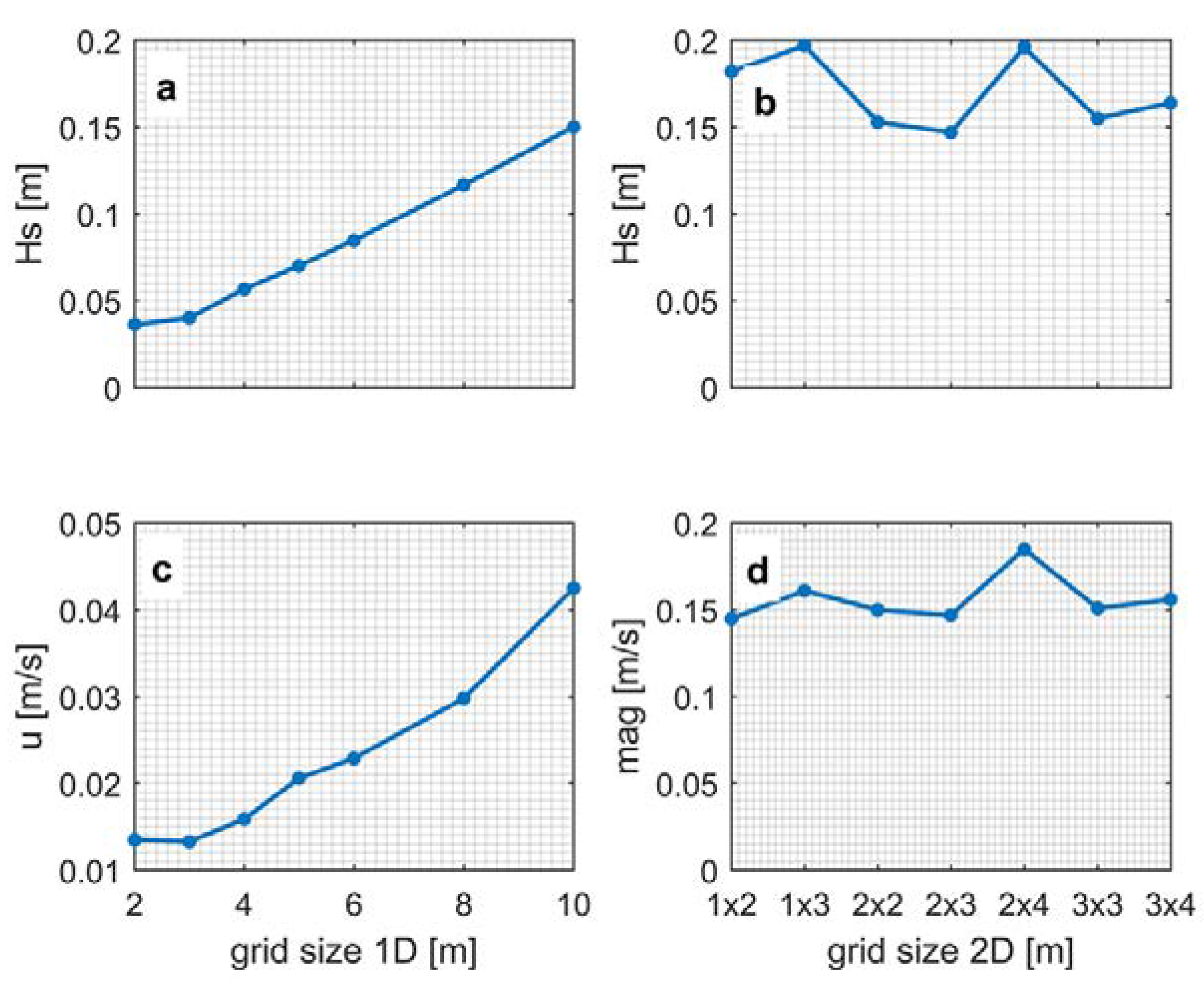
To determine the grid cell size for this study, we conducted a series of sensitivity analyses to find the largest grid cell size that produced suitable results. Given the relatively large (for a phase resolving model) size of the domain (1.8 km by 3 km domain), determining the coarsest possible grid size will also minimize the computational time required for each run. A series of models was first run in 1D using various grid size of 1 to 5 m to identify the suitable cross-shore grid size. This was done by comparing the resulting wave height and mean cross-shore (u) currents of the coarser grid resolution to the result from the 1 m grid as the reference. The cross-shore profile used in the 1D models is from the southern reef (red line in Figure 1a). Each simulation was run for 30 min (excluding the spin-up time of 15 min) with two equidistant vertical layers and a single wave condition of Hs of 3.14 m and Tp of 13.4 s with JONSWAP spectrum that corresponded to the average wave height during the observation period. The RMSE of modeled significant wave height (Figure A1a) and cross-shore velocity (Figure A1c) parameters between 1m grid size and coarser grids showed the difference between SWASH output with 2 m and that of 3 m was not significant. i.e., less than 1 cm and 1 cm/s for Hs and cross-shore currents respectively, yet the error considerably increased when we used grid size ≥4 m. Hence, we considered cross-shore grid resolution of 2 or 3 m to be suitable for the study.
The optimal alongshore grid size was determined by comparing modeled Hs and velocity components in 2D to a reference grid of 1 × 1 m. For this purpose, we carried out 7 simulations with similar model setting to that of the 1D model in different sizes (cross-shore size of 1–3 m and longshore size of 2–4 m, see Figure A1d) and compare the result among them. The result showed that for all the 2D grids, the errors between the tested grids and the reference of 1 × 1m for Hs and current magnitude were not higher than ~0.05 m and ~0.04 m/s respectively (Figure A1b,d). We also identified grid sizes with a larger ratio between the cross- and alongshore dimension (i.e., 1 × 3 and 2 × 4 m) had larger errors. Despite relatively small differences among the tested 2D grid resolutions, there was a large difference among the simulation time needed to finish the simulations as shown in Figure A2.
The simulation with a grid size of 3 × 4 m had the lightest computation need of 137.28 core-hours for a 90 min simulation (i.e., 1 h simulation and 30 min spin-up), 3.5 times faster than the 2 × 3 m grid which we considered to be the best result. Considering the small difference of output error (with the desired accuracy), and the computational time among tested grid resolutions, we concluded the size of 3 m (cross-shore) × 4 m (alongshore) would be the optimum grid for the 2D simulation and used in this study.
Figure A1. RMSE for wave height (a,b) and cross-shore velocity magnitude (c,d) of a range of grid cell sizes relative to the reference case with 1 m resolution. The left panels (a,c) are for the 1D case and right (b,d) for the 2D case.
Jmse 08 00877 g0a1
Figure A2. Normalized (to the coarsest grid 3 × 4 m) computational cost.
Jmse 08 00877 g0a2

References

  1. Buckley, M.; Lowe, R.; Hansen, J. Evaluation of nearshore wave models in steep reef environments. Theor. Comput. Obs. Oceanogr. 2014, 64, 847–862. [Google Scholar] [CrossRef]
  2. Drost, E.J.F.; Cuttler, M.V.W.; Lowe, R.J.; Hansen, J.E. Predicting the hydrodynamic response of a coastal reef-lagoon system to a tropical cyclone using phase-averaged and surfbeat-resolving wave models. Coast. Eng. 2019, 152, 103525. [Google Scholar] [CrossRef]
  3. Monismith, S.G. Hydrodynamics of Coral Reefs. Annu. Rev. Fluid Mech. 2007, 39, 37–55. [Google Scholar] [CrossRef]
  4. Lowe, R.J.; Falter, J.L. Oceanic Forcing of Coral Reefs. Annu. Rev. Mar. Sci. 2015, 7, 43–66. [Google Scholar] [CrossRef] [PubMed] [Green Version]
  5. Winter, G.; Castelle, B.; Lowe, R.J.; Hansen, J.E.; McCall, R. When is flow re-entrainment important for the flushing time in coastal reef systems? Cont. Shelf Res. 2020, 206, 104194. [Google Scholar] [CrossRef]
  6. Sheremet, A.; Kaihatu, J.M.; Su, S.F.; Smith, E.R.; Smith, J.M. Modeling of nonlinear wave propagation over fringing reefs. Coast. Eng. 2011, 58, 1125–1137. [Google Scholar] [CrossRef]
  7. Filipot, J.-F.; Cheung, K.F. Spectral wave modeling in fringing reef environments. Coast. Eng. 2012, 67, 67–79. [Google Scholar] [CrossRef]
  8. Roelvink, D.; McCall, R.; Mehvar, S.; Nederhoff, K.; Dastgheib, A. Improving predictions of swash dynamics in XBeach: The role of groupiness and incident-band runup. Coast. Eng. 2018, 134, 103–123. [Google Scholar] [CrossRef]
  9. Van Dongeren, A.; Lowe, R.; Pomeroy, A.; Trang, D.M.; Roelvink, D.; Symonds, G.; Ranasinghe, R. Numerical modeling of low-frequency wave dynamics over a fringing coral reef. Coast. Eng. 2013, 73, 178–190. [Google Scholar] [CrossRef]
  10. Zijlema, M.; Stelling, G.S. Efficient computation of surf zone waves using the nonlinear shallow water equations with non-hydrostatic pressure. Coast. Eng. 2008, 55, 780–790. [Google Scholar] [CrossRef]
  11. Jeschke, A.; Pedersen, G.; Vater, S.; Behrens, J. Depth-averaged Non-hydrostatic Extension for Shallow Water Equations with Quadratic Vertical Pressure Profile: Equivalence to Boussinesq-type Equations. Int. J. Numer. Methods Fluids 2017, 84, 569–583. [Google Scholar] [CrossRef]
  12. Kazolea, M.; Ricchiuto, M. On wave breaking for Boussinesq-type models. Ocean. Model. 2018, 123, 16–39. [Google Scholar] [CrossRef] [Green Version]
  13. Madsen, P.A.; Bingham, H.B.; Liu, H. A new Boussinesq method for fully nonlinear waves from shallow to deep water. J. Fluid Mech. 2002, 462, 1–30. [Google Scholar] [CrossRef]
  14. Pomeroy, A.; Lowe, R.; Symonds, G.; Van Dongeren, A.; Moore, C.C.C. The dynamics of infragravity wave transformation over a fringing reef. J. Geophys. Res. Ocean. 2012, 117. [Google Scholar] [CrossRef] [Green Version]
  15. Lashley, C.H.; Roelvink, D.; van Dongeren, A.; Buckley, M.L.; Lowe, R.J. Nonhydrostatic and surfbeat model predictions of extreme wave run-up in fringing reef environments. Coast. Eng. 2018, 137, 11–27. [Google Scholar] [CrossRef] [Green Version]
  16. Quataert, E.; Storlazzi, C.; van Rooijen, A.; Cheriton, O.; van Dongeren, A. The influence of coral reefs and climate change on wave-driven flooding of tropical coastlines. Geophys. Res. Lett. 2015, 42, 6407–6415. [Google Scholar] [CrossRef]
  17. Ma, G.; Shi, F.; Kirby, J.T. Shock-capturing non-hydrostatic model for fully dispersive surface wave processes. Ocean. Model. 2012, 43, 22–35. [Google Scholar] [CrossRef]
  18. Zijlema, M.; Stelling, G.; Smit, P. SWASH: An operational public domain code for simulating wave fields and rapidly varied flows in coastal waters. Coast. Eng. 2011, 58, 992–1012. [Google Scholar] [CrossRef]
  19. Lynett, P. Nearshore Wave Modeling with High-Order Boussinesq-Type Equations. J. Waterw. Port. Coast. Ocean. Eng. 2006, 132, 348–357. [Google Scholar] [CrossRef] [Green Version]
  20. Brocchini, M. A reasoned overview on Boussinesq-type models: The interplay between physics, mathematics and numerics. Proc. R. Soc. A Math. Phys. Eng. Sci. 2013, 469, 20130496. [Google Scholar] [CrossRef] [Green Version]
  21. Masselink, G.; Tuck, M.; McCall, R.; van Dongeren, A.; Ford, M.; Kench, P. Physical and Numerical Modeling of Infragravity Wave Generation and Transformation on Coral Reef Platforms. J. Geophys. Res. Ocean. 2019, 124, 1410–1433. [Google Scholar] [CrossRef]
  22. Shi, J.; Zhang, C.; Zheng, J.; Tong, C.; Wang, P.; Chen, S. Modelling Wave Breaking across Coral Reefs Using a Non-Hydrostatic Model. J. Coast. Res. 2018, 85, 501–505. [Google Scholar] [CrossRef]
  23. Wei, Z.; Jia, Y. Non-hydrostatic finite element model for coastal wave processes. Coast. Eng. 2014, 92, 31–47. [Google Scholar] [CrossRef]
  24. Roeber, V.; Cheung, K.F. Boussinesq-type model for energetic breaking waves in fringing reef environments. Coast. Eng. 2012, 70, 1–20. [Google Scholar] [CrossRef]
  25. Rijnsdorp, D.P.; Ruessink, G.; Zijlema, M. Infragravity-wave dynamics in a barred coastal region, a numerical study. J. Geophys. Res. Ocean. 2015, 120, 4068–4089. [Google Scholar] [CrossRef] [Green Version]
  26. Nicolae Lerma, A.; Pedreros, R.; Robinet, A.; Sénéchal, N. Simulating wave setup and runup during storm conditions on a complex barred beach. Coast. Eng. 2017, 123, 29–41. [Google Scholar] [CrossRef]
  27. Torres-Freyermuth, A.; Mariño-Tapia, I.; Coronado, C.; Salles, P.; Medellín, G.; Pedrozo-Acuña, A.; Silva, R.; Candela, J.; Iglesias-Prieto, R. Wave-induced extreme water levels in the Puerto Morelos fringing reef lagoon. Nat. Hazards Earth Syst. Sci. 2012, 12, 3765–3773. [Google Scholar] [CrossRef] [Green Version]
  28. Sous, D.; Dodet, G.; Bouchette, F.; Tissier, M. Momentum Balance Across a Barrier Reef. J. Geophys. Res. Ocean. 2020, 125, e2019JC015503. [Google Scholar] [CrossRef]
  29. Risandi, J.; Hansen, J.E.; Lowe, R.J.; Rijnsdorp, D.P. Shoreline Variability at a Reef-Fringed Pocket Beach. Front. Mar. Sci. 2020, 7. [Google Scholar] [CrossRef]
  30. Mory, M.; Hamm, L. Wave height, setup and currents around a detached breakwater submitted to regular or random wave forcing. Coast. Eng. 1997, 31, 77–96. [Google Scholar] [CrossRef]
  31. Beetham, E.; Kench, P.S.; O’ Callaghan, J.; Popinet, S. Wave transformation and shoreline water level on Funafuti Atoll, Tuvalu. J. Geophys. Res. Ocean. 2016, 121, 311–326. [Google Scholar] [CrossRef] [Green Version]
  32. Rijnsdorp, D.P.; Smit, P.B.; Zijlema, M.; Reniers, A.J.H.M. Efficient non-hydrostatic modelling of 3D wave-induced currents using a subgrid approach. Ocean. Model. 2017, 116, 118–133. [Google Scholar] [CrossRef] [Green Version]
  33. Feddersen, F.; Clark, D.B.; Guza, R.T. Modeling surf zone tracer plumes: 1. Waves, mean currents, and low-frequency eddies. J. Geophys. Res. Ocean. 2011, 116, C11027. [Google Scholar] [CrossRef] [Green Version]
  34. Smit, P.; Zijlema, M.; Stelling, G. Depth-induced wave breaking in a non-hydrostatic, near-shore wave model. Coast. Eng. 2013, 76, 1–16. [Google Scholar] [CrossRef]
  35. Lowe, R.J.; Falter, J.L.; Monismith, S.G.; Atkinson, M.J. A numerical study of circulation in a coastal reef-lagoon system. J. Geophys. Res. Ocean. 2009, 114, C06022. [Google Scholar] [CrossRef]
  36. Willmott, C.J. Statistics for the evaluation and comparison of models. J. Geophys. Res. Ocean. 1985, 90, 8995–9005. [Google Scholar] [CrossRef] [Green Version]
  37. Hansen, J.E.; Raubenheimer, B.; List, J.H.; Elgar, S. Modeled alongshore circulation and force balances onshore of a submarine canyon. J. Geophys. Res. Ocean. 2015, 120, 1887–1903. [Google Scholar] [CrossRef]
  38. Pearson, S.; Storlazzi, C.; van Dongeren, A.; Tissier, M.; Reniers, A. A Bayesian-Based System to Assess Wave-Driven Flooding Hazards on Coral Reef-Lined Coasts. J. Geophys. Res. Ocean. 2017, 122, 10099–10117. [Google Scholar] [CrossRef] [Green Version]
  39. Lowe, R.J.; Shavit, U.; Falter, J.L.; Koseff, J.R.; Monismith, S.G. Modeling flow in coral communities with and without waves: A synthesis of porous media and canopy flow approaches. Limnol. Oceanogr. 2008, 53, 2668–2680. [Google Scholar] [CrossRef]
  40. Rosman, J.H.; Hench, J.L. A framework for understanding drag parameterizations for coral reefs. J. Geophys. Res. Ocean. 2011, 116, C08025. [Google Scholar] [CrossRef] [Green Version]
  41. Péquignet, A.C.N.; Becker, J.M.; Merrifield, M.A. Energy transfer between wind waves and low-frequency oscillations on a fringing reef, Ipan, Guam. J. Geophys. Res. Ocean. 2014, 119, 6709–6724. [Google Scholar] [CrossRef]
  42. Gomes, E.R.; Mulligan, R.P.; Brodie, K.L.; McNinch, J.E. Bathymetric control on the spatial distribution of wave breaking in the surf zone of a natural beach. Coast. Eng. 2016, 116, 180–194. [Google Scholar] [CrossRef]
  43. Fringer, O.B.; Dawson, C.N.; He, R.; Ralston, D.K.; Zhang, Y.J. The future of coastal and estuarine modeling: Findings from a workshop. Ocean. Model. 2019, 143, 101458. [Google Scholar] [CrossRef]
  44. Henderson, S.M.; Bowen, A.J. Simulations of dissipative, shore-oblique infragravity waves. J. Phys. Oceanogr. 2003, 33, 1722–1732. [Google Scholar] [CrossRef]
  45. de Bakker, A.T.M.; Tissier, M.F.S.; Ruessink, B.G. Shoreline dissipation of infragravity waves. Cont. Shelf Res. 2014, 72, 73–82. [Google Scholar] [CrossRef]
  46. Feddersen, F.; Guza, R.T.; Elgar, S.; Herbers, T.H.C. Alongshore momentum balances in the nearshore. J. Geophys. Res. Ocean. 1998, 103, 15667–15676. [Google Scholar] [CrossRef]
  47. van Rooijen, A.A.; McCall, R.T.; van Thiel de Vries, J.S.M.; van Dongeren, A.R.; Reniers, A.J.H.M.; Roelvink, J.A. Modeling the effect of wave-vegetation interaction on wave setup. J. Geophys. Res. Ocean. 2016, 121, 4341–4359. [Google Scholar] [CrossRef] [Green Version]
  48. Pomeroy, A.W.M.; Lowe, R.J.; Ghisalberti, M.; Storlazzi, C.; Symonds, G.; Roelvink, D. Sediment transport in the presence of large reef bottom roughness. J. Geophys. Res. Ocean. 2017, 122, 1347–1368. [Google Scholar] [CrossRef]
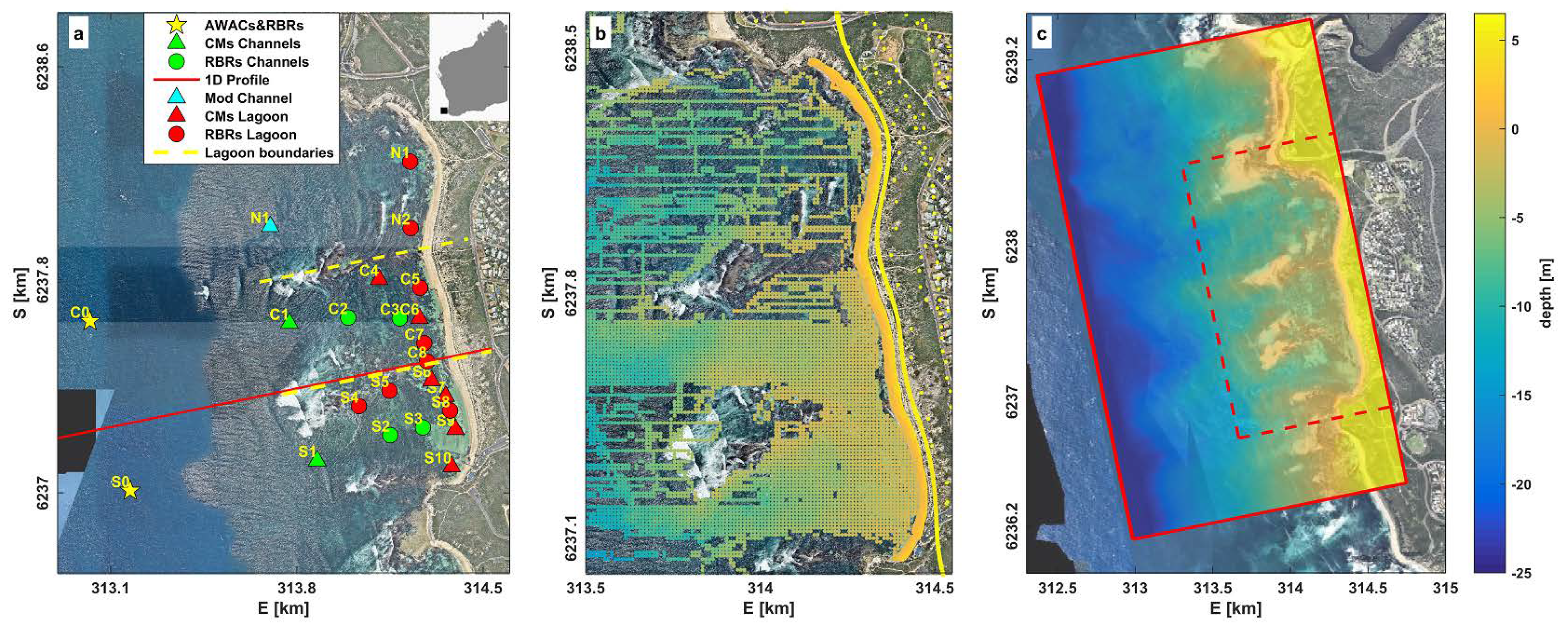
Figure 1. (a) Aerial image and instrument locations (see inset for location in Australia). The red line is the position of the cross-shore transect used for the 1D model (Appendix A). Dashed yellow lines separate the lagoon into 3 area behind the offshore reefs. (b) Bathymetry survey data used to generate the bathymetry grid. (c) Numerical domain (the red box with solid lines, the left side of the box indicates the offshore boundary) and 1 × 1 m grid interpolated bathymetry used in the model. The red dashed box indicates the area of the model output shown in subsequent figures. Source of the aerial image is www.nearmap.com.
Jmse 08 00877 g001
Figure 2. Hourly observation of offshore conditions at site C0: (a) significant wave height, (b) peak period, (c) peak direction, and (d) mean water level. Vertical red lines indicate the 17 scenarios simulated in SWASH.
Jmse 08 00877 g002
Figure 3. Calculated kinetic energy (KE), potential energy (PE) and enstrophy (Z) integrated over the model domain versus simulation time.
Jmse 08 00877 g003
Figure 4. Snapshot of (a) modeled sea surface elevation, (b) hourly SS significant wave height, (c) IG significant wave height and (d) averaged currents fields for a scenario with the average conditions during field observations (Hs0 = 3.14 m, Tp0 = 13.4 s and a water level of −0.18 m at offshore boundary). The current vectors are in logarithmic scale. Black lines at a, b and c are the depth contours.
Jmse 08 00877 g004
Figure 5. (a) Mean setup of scenario with averaged wave height during observation. (b) Mean setup averaged over 17 scenarios.
Jmse 08 00877 g005
Figure 6. The influence of friction coefficient (cf) variability to the average (across each grouping of sensors, offshore, channels, and lagoon) RMS error (a,c,e,g,i,k) and bias (b,d,f,h,j,l) of modeled hydrodynamics within the study area, see Figure 1 to refer the sensor locations. The green and red vertical lines represent the standard deviations whereas the vertical black line indicates a cf of 0.05.
Jmse 08 00877 g006
Figure 7. Comparison between observed and modeled SS waves (ac), IG waves (df), and setup (g,h), for the 17 scenarios using a constant bottom friction cf = 0.05. Green, black and red colors on the figures represent the respective North, Central and South parts of the lagoon (see Figure 1a). Numbers on the subplots represent average values of the respective Willmott Skills, RMSEs and Bias (refer to Table 2).
Jmse 08 00877 g007
Figure 8. Time series comparison of SS wave (ad), IG wave heights (eh), and wave setup (ik) between the model (circles) and observations (lines) at the various locations that represent North, Central and South part of the site.
Jmse 08 00877 g008
Figure 9. Observations (red color) and model (black color) results of (a) time-averaged current vectors computed over 17 (hour) scenarios with gray lines are contours at 5 to 15 m depth (see the labels). (b) Average current magnitude and directions obtained from 17 scenarios of SWASH model. The current vectors in (b) are plotted using a logarithmic scale.
Jmse 08 00877 g009
Figure 10. Comparison between observed and modeled current magnitude and direction, with colors denoting the offshore significant wave heights at C0 (colors). Observations (a,b) in the channels and (c,d) in the lagoon. Circles and triangles on the figures distinguish observations from the Central and South regions, respectively.
Jmse 08 00877 g010
Figure 11. Modeled mean (hourly) current velocity at South (S1), Central (C1) and North (N1) channels (refer to Figure 1a for the locations) versus observed wave height at the AWAC (C0).
Jmse 08 00877 g011
Figure 12. (a) Spatial variability of bottom friction (cf) which was estimated from aerial images. The comparison between data-model with uniform and spatially-variable cf for (b) SS waves, (c) IG waves, (d) current magnitude and (e) direction.
Jmse 08 00877 g012
Table 1. Site label, instrument configuration and location.
Site LabelInstrument TypeApproximate Depth (m)Sampling Frequency (Hz)Location
Northern area
N1RBR Solo3.52Lagoon
N2RBR Solo2.52Lagoon
Central area
C0AWAC/RBR21.31Offshore
C1RDI Workhorse7.91Channel
C2RBR Solo4.71Channel
C3RBR Solo4.02Channel
C4RDI Workhorse4.01Lagoon
C5RBR Solo2.12Lagoon
C6Nortek Aquadopp3.41Lagoon
C7RBR Solo3.02Lagoon
C8RBR Solo2.62Lagoon
Southern area
S0AWAC/RBR19.01Offshore
S1RDI Workhorse7.61Channel
S2RBR Solo5.52Channel
S3RBR Solo3.62Channel
S4RBR Solo2.92Lagoon
S5RBR Solo2.92Lagoon
S6Nortek Aquadopp2.11Lagoon
S7Nortek Vector 3.32Lagoon
S8RBR Solo2.32Lagoon
S9Nortek Vector2.52Lagoon
S10Nortek Aquadopp2.31Lagoon
Table 2. Summary of Willmott Skill (WS), RMSE and Bias calculated at each sensor averaged across the 17 scenarios.
Sensor LocationSS Wave HeightsIG Wave HeightsSetupCurrent MagnitudeCurrent Direction
WS
[-]
RMSE
[m]
Bias
[m]
WS
[-]
RMSE
[m]
Bias
[m]
WS
[-]
RMSE
[m]
Bias
[m]
WS
[-]
RMSE
[m/s]
Bias
[m/s]
WS
[-]
RMSE
[°]
Bias
[°]
North
N20.790.130.110.850.060.040.840.050.04N/AN/AN/AN/AN/AN/A
N30.290.230.230.880.030.020.890.040.04N/AN/AN/AN/AN/AN/A
Central
C00.920.29−0.020.620.080.06N/AN/AN/A0.470.09−0.070.52132.85−65.91
C10.550.610.590.830.080.07N/AN/AN/A0.660.16−0.060.2545.23−43.77
C20.340.370.360.90.040.030.880.040.04N/AN/AN/AN/AN/AN/A
C30.30.210.210.870.030.000.850.050.05N/AN/AN/AN/AN/AN/A
C40.850.06−0.040.860.03−0.01N/AN/AN/A0.540.040.000.2566.41−58.91
C50.270.260.250.870.040.000.860.050.05N/AN/AN/AN/AN/AN/A
C60.290.210.200.840.040.000.880.050.040.32 0.030.020.78131.8130.55
C70.490.130.130.840.04−0.010.850.050.05N/AN/AN/AN/AN/AN/A
C80.770.060.050.820.04−0.010.770.070.07N/AN/AN/AN/AN/AN/A
South
S00.960.23−0.040.730.090.08N/AN/AN/A0.460.08−0.070.44128.55−105.02
S10.640.580.550.770.120.100.380.060.050.610.33−0.300.1423.64−23.42
S20.850.13−0.050.870.040.020.830.050.05N/AN/AN/AN/AN/AN/A
S30.850.080.000.860.040.010.780.070.06N/AN/AN/AN/AN/AN/A
S40.680.080.040.810.060.040.840.050.05N/AN/AN/AN/AN/AN/A
S50.820.060.010.830.050.020.790.060.06N/AN/AN/AN/AN/AN/A
S60.710.06−0.010.850.04−0.010.870.050.040.390.11−0.090.57103.4940.19
S70.770.07−0.030.820.05−0.01N/A N/AN/A0.290.06−0.050.2283.9378.43
S80.80.06−0.010.840.05−0.010.760.070.07 N/AN/AN/A N/AN/AN/A
S90.80.06−0.020.840.04−0.010.620.110.100.430.04−0.030.1189.2888.47
S100.350.180.180.720.05−0.020.760.070.070.350.020.020.4273.29−62.45
N/A represent when the comparison is not available, either due to unavailability or errors on the sensors. Negative bias in current directions are counter-clockwise; Colors in the table represent the skill of model at each sensor location where green is good, orange is moderate and red is poor skill, respectively.
Publisher’s Note: MDPI stays neutral with regard to jurisdictional claims in published maps and institutional affiliations.