Article

Re-Evaluation of Fatigue Thickness Effect Based on Fatigue Test Database

Offshore Design Engineering Ltd., London SW19 4DR, UK
*
Author to whom correspondence should be addressed.
J. Mar. Sci. Eng. 2020, 8(11), 895; https://doi.org/10.3390/jmse8110895
Submission received: 10 September 2020 / Revised: 21 October 2020 / Accepted: 30 October 2020 / Published: 10 November 2020
(This article belongs to the Special Issue Offshore and Subsea Structures)

Abstract

:
This paper reassesses the detrimental effect on fatigue performance of welded structural steel joints due to thicker sections based on an extensive fatigue strength test database, taken from research programmes worldwide over the past half century, mostly from the offshore oil and gas and marine industries. The data entries in the database were evaluated to ensure its data integrity. Statistical analyses on these S-N data were performed with or without the thickness correction at different exposure levels to a corrosive environment, in order to re-evaluate the suitability of current standards in regard to the thickness effect. The study concentrated on T-joints, transverse butt-welded joints and tubular joints, as these are the most commonly used joint types in the offshore wind industry. The analysis indicates a general agreement of fatigue strength with the thickness effects in current standards for in-air conditions, but great conservatism for corrosive environments. In addition, the statistical models determined in this study can be used for a broader range of studies, such as probabilistic fatigue analysis.

1. Introduction

Metal fatigue failure is a process where cyclic loading causes a crack to initiate and propagate through the thickness of a member. While fatigue material strength, defined as stress amplitude S for a given number of cycles N, is a material property, it also depends on loading regime and stress ratios [1]. For the offshore environment, a commonly adopted simplified fatigue design approach is to use a combination of load simulation (deterministic, spectral or time domain), rainflow method and miner’s rule, and therefore test data from constant amplitude can be used. This simplified approach can bring uncertainties. Sørensen [2] has suggested a three-band categorisation for modelling the uncertainty of wind load depending on the accuracy and the assessment method selected for the wind measurement/analysis. For example, for offshore wind turbine structural fatigue assessment methods based on time domain analysis from real site data and turbine models will have fewer uncertainties than methods based on simplified loading models. Zhao et al. [3] provided a comprehensive discussion of uncertainty models in the fatigue design process. These uncertainties for the simplified approach have been recognised in standard development and mitigated by the use of the design fatigue factors [4].
This paper addresses the aspect of fatigue strength variation with thickness under air or corrosive conditions, in particular for steel welded joints with the implicit assumption of constant amplitude loading.
It was recognised by Gurney [5] in 1979 that thicker sections have shorter fatigue lives N for the same stress amplitude S. To consider the negative effect on fatigue performance due to thick sections, Gurney [5] proposed the so-called thickness correction factor to the S-N curve, based on experimental results, which has been adopted by current fatigue standards. However, those tests used to derive the parameters of the correction factor equation were mostly conducted in the 1980s and 1990s when there was considerable research investment available from the offshore oil and gas industry and were for much thinner sections than those used in the offshore wind industry. Current offshore wind turbine foundations, such as monopiles, are designed with sections with a wall thickness up to 100 mm in order to cope with the increasing turbine capacity and environmental loadings. Therefore, considerable uncertainties exist in these S-N curves for thick sections, leading to conservative design codes in order to maintain confidence against fatigue failure.
This paper will present the findings from a wide range of test databases to identify or confirm uncertainties and the current assumptions. The following approach has been adopted in this research:
(1)
Introduce the concept of thickness correction factors by Gurney and in current standards and then relate these factors to general physical or statistical causes.
(2)
Present relevant types of typical weld geometry for S-N curve classifications and test data grouping.
(3)
Conduct a literature review of thickness correction factors for the associated joint types and in general terms.
(4)
Review the fatigue test database from tests conducted in the last 40 years and select test data with sufficient data integrity for further statistical analysis.
(5)
Conduct statistical analysis of fatigue strength with different thickness groups and different S-N curve categories to gain insight into the uncertainties of fatigue strength associated with individual thickness.

2. Literature Review

2.1. Overview of Thickness Effect and Correction

In 1979, Gurney [5] proposed the thickness correction factor accordingly using the following:
Δ σ c = Δ σ ( T t r e f ) k
where ∆σc is the stress range with thickness correction, ∆σ is the uncorrected stress range, T is the thickness of the main section/plate, tref is the reference thickness and k is the power exponent for thickness correction.
In current standards, such as IIW-1823-07 [6], DNVGL-RP-C203 [4], ISO 19902 [7], the scale factor is a function of the effective thickness Teff in relation to a reference thickness tref with a power quotient k. This can be expressed using Gurney’s equation:
Δ σ c = Δ σ ( T e f f t r e f ) k
Some works regarding the following have been conducted in more recent studies to improve the thickness correction factor:
  • Size effect and effective thickness.
  • Revision of the power exponent k.
The three main causes of the thickness effect are:
  • Statistical: Thicker plates can have a higher probability of imperfection to start crack initiation.
  • Fabrication: Residual stress of a thicker plate is higher due to more restraint.
  • Geometry: The main geometric cause is that a thicker plate has a lower stress gradient across the thickness than a thinner plate. The other two causes can be that a thicker plate may have a relatively smaller radius (ai = ai, but ai/t1 < ai/t2, [8]) of the welding profile at the weld toe, and a thicker section can introduce a plane strain state. Due to the presence of a steeper stress gradient in a thinner section, a small crack (notch) close to the surface of a small specimen will experience a lower strain than a small crack (notch) close to the surface of a thick specimen, for the same stress at the surface. Overall, the geometry effect was considered as the dominant cause of the thickness effect.

2.2. Typical Joints in Current Standards

The most frequently used joint/weld types in the offshore wind industry, as well as the offshore oil and gas industry ([4,6,9]), are:
  • T-joints.
  • Transverse butt-welded joints.
  • Tubular joints.

2.2.1. T-Joints

A T-joint, or cruciform joint, refers to the welded point of two perpendicular plates, forming a letter T. The welding type of a T-joint covers fillet weld, partial penetration butt weld and full penetration weld. The weld detail of a T-joint with fillet weld is shown in Figure 1.

2.2.2. Transverse Butt-Welded Joints

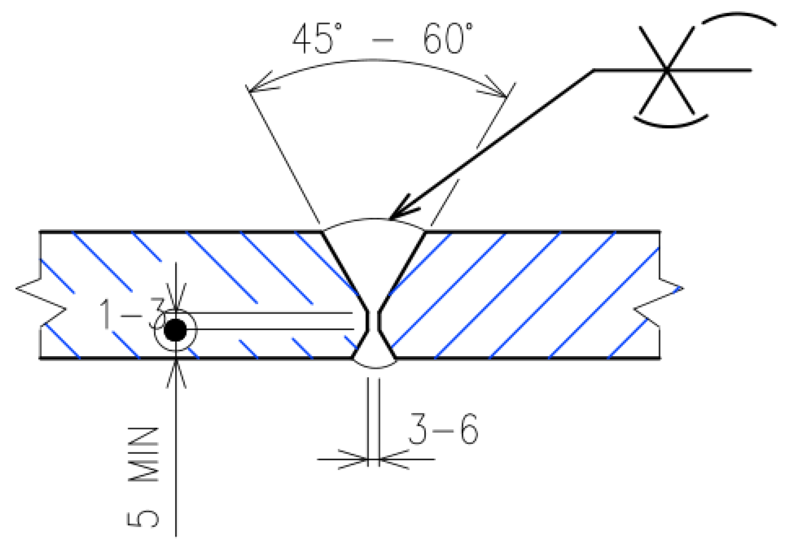
A transverse butt-welded joint is defined as two transverse splices or plates or flats welded with double-sided full penetration weld, as commonly found in connections for monopiles. This type of weld represents the characteristic of circumferential girth weld as well. Typical weld detail of a transverse butt weld is shown in Figure 2.

2.2.3. Tubular Joints

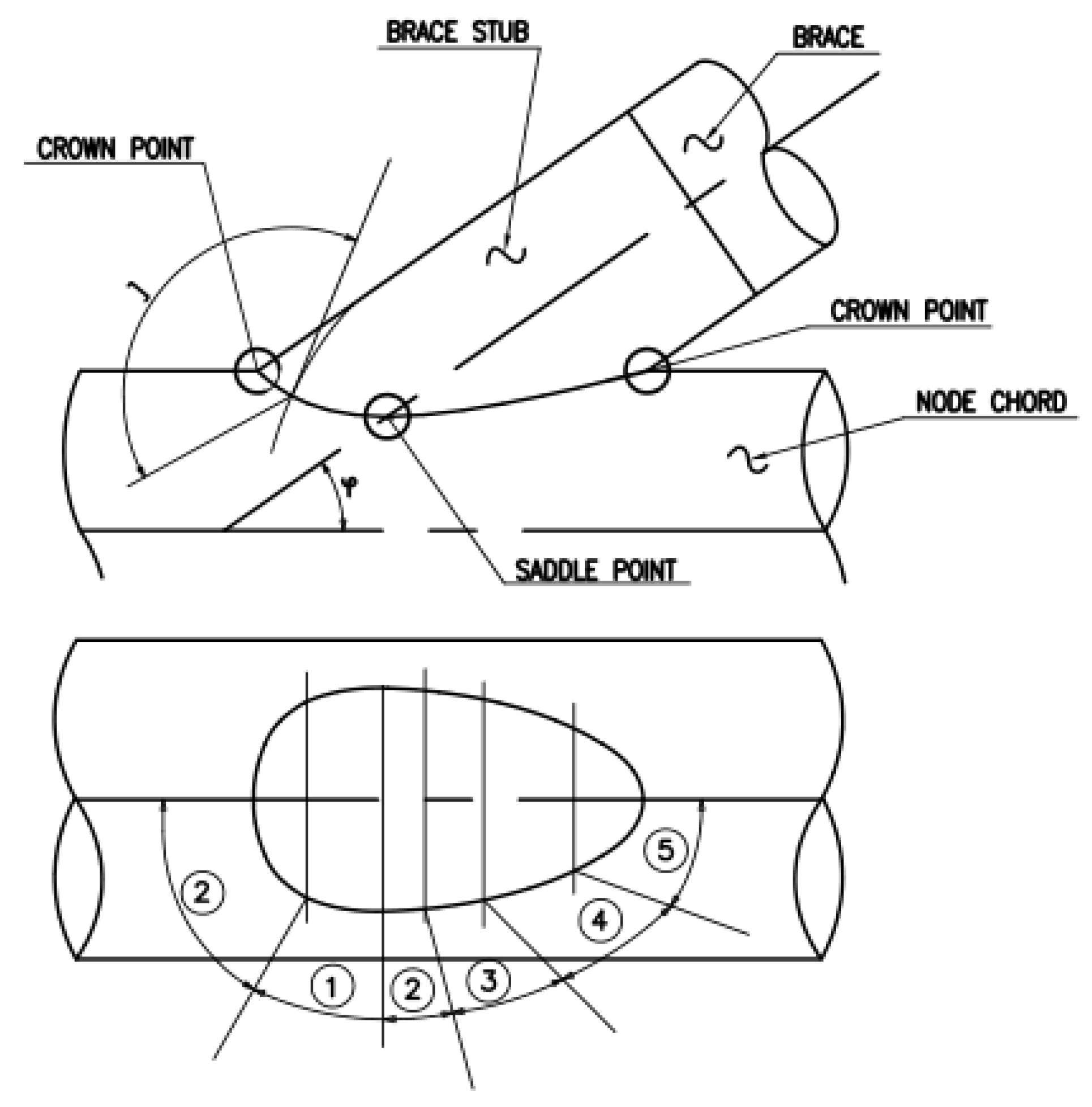
The definition of tubular joint is universally acknowledged as a brace to chord connection of two tubulars. A typical tubular joint connection layout is illustrated in Figure 3, where the numbers indicate the locations of weld cross-sections. The welding types of tubular joint include either single-sided or double-sided full penetration weld.
The three typical joint types are respectively categorised to three S-N curves, F curve, D curve and T curve in the DNVGL-RP-C203 [4] specification. Table 1 shows the reference thickness tref and the power exponent k in the thickness correction equation of various standards.
Several combinations of reference thickness and power exponent are defined in different standards. For analysis in this study, specifications in DNVGL-RP-C203 [4] were selected as the reference standard.

2.3. General Uncertianties of Thickness Correction Factors

The thickness correction factor for each of the S-N curves is based on the assumption that fatigue strength reduction is scalable by thickness. However, the following should be noted:
  • Not all factors affecting fatigue strength are scalable or proportionable, such as corrosion effect.
  • The basis for scale may not be the thickness alone, as weld width and attachment length will also contribute, known as the size effect.
  • The scale can be different for different weld classes and not uniform for the same S-N category.
The thickness correction factor is based on nominal stress but stresses in some S-N curves are based on hotspot stresses. Application of the use of hotspot stresses may need further investigation.

2.4. Effective Thickness for Size Effect

Some studies have shown that not only the thickness affects the fatigue performance, but also the local geometry. As the thickness of the attachment increases, more stress is attracted to the weld toe region and a fatigue crack is initiated earlier. Therefore, for some specific joint types, “size effect” is a more appropriate term to describe the behaviour rather than “thickness effect”. For example, a butt weld of limited width will show less size effect, and could be significantly reduced by grinding, such that the weld notch is reduced. The fatigue performance of a cruciform joint with relatively thinner transverse attachment also improves, as less stress at the crack tip region in a thinner plate can lead to a lower crack growth rate.
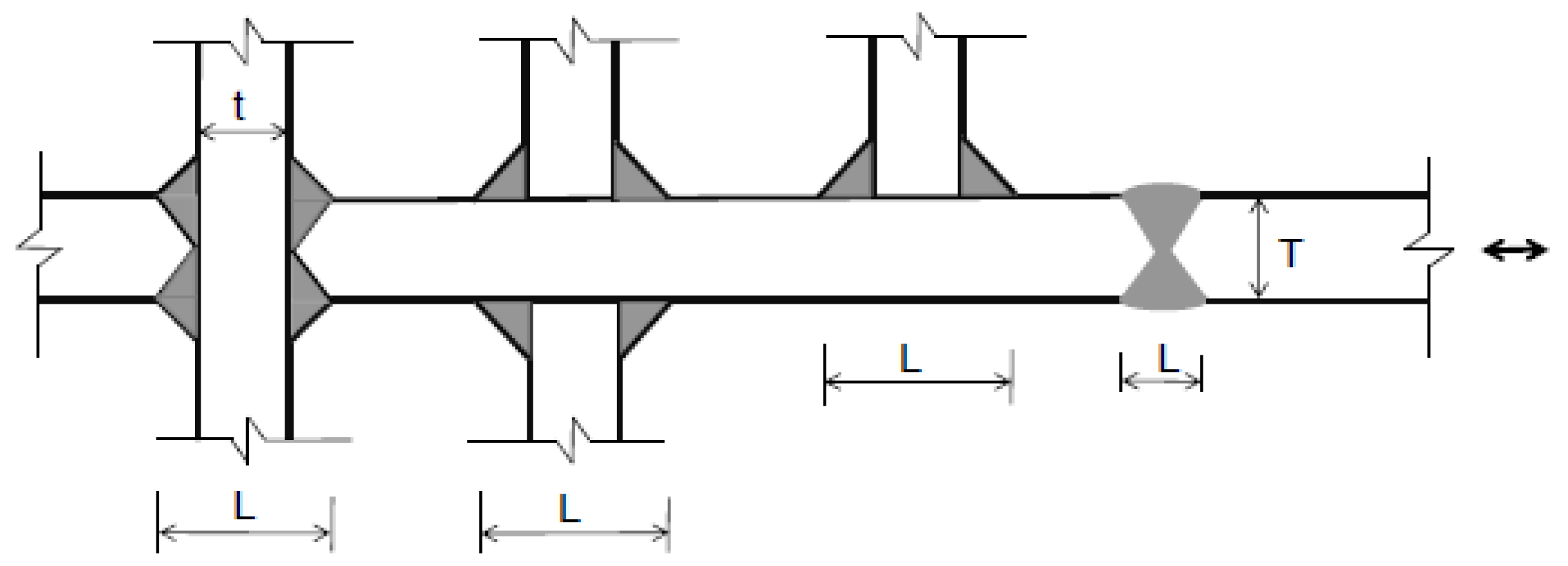
Size effect is also observed in stress relief tests, with about the same effectiveness as the as-welded specimens. Gurney [11] noted that thickness is not the only geometric factor and proposed a method to assess size effect by using effective thickness Teff in the thickness correction equation to replace T. For T-joints and transverse butt-welded joints, as shown in Figure 4, Gurney introduced the effective thickness calculation to substitute the section thickness T as follows:
i f L T > 2 ,   t h e n   T e f f = T i f L T 2 , t h e n   T e f f = 0.5 L   o r   T e f f = t r e f ,   w h i c h e v e r   i s   l a r g e r
where L is the length of attachment indicated in Figure 4.
IIW [6] and IACS [12] redefined the effective thickness to illustrate the size effect as follows:
T e f f = m i n ( L 2 , T ) ,   b u t   T e f f t r e f
In a more recent study by Lotsberg [13], an updated equation of effective thickness for butt welds and cruciform joints has been illustrated and incorporated into DNVGL-RP-C203 [4] at a later stage, where:
T e f f = min ( 14   m m + 0.66 L , T ) ,   T e f f t r e f
This specification can be used for cruciform joints, butt welds and short attachments, such as shear keys welded to steel plates, piles used in OWT piles or large-diameter monopiles.

2.5. Revision of Power Exponent k

Different values of k have been specified in standards, ranging from 0.1 to 0.3. A study by Lotsberg [13] has discussed the influence of k on fatigue life.
Usual standards use one k value for each S-N curve category. However, the power exponent can be also stress/environment/geometry dependent. In a study by Haagensen [14], the background of the thickness effect has been explained as when the stress gradient at the surface of a thinner section is steeper. Thus, the surface grain will be subjected to lower strain under the same surface stress compared to a thicker section. Hence, the following equation has been introduced by Berge [15]:
k = 0.1 + 0.14 log K t
where Kt is the stress intensity factor.
Cole et al. [16], on the other hand, stated that the thickness effect is dependent on the stress range, which can be presented by the following equation:
k = 3 [ K ( Δ σ × C ) ]
where K and C are constants that depend on exposure to a corrosive environment (in-air or cathodic protection) and different types of joint.

3. Fatigue S-N Database

Data analysis is a very powerful tool to evaluate the fitness of current standards against the actual fatigue behaviour. As a result, a sound database with clearly defined attributes, sizable sample quantities and a diverse variety of characteristics is essential.
The database used in this study has taken input from a variety of research programmes worldwide over the past half century in the offshore oil and gas, renewable and other industries. Most of the fatigue experiments were conducted in the 1980s and the 1990s, when many tests were produced in large-scale programmes. There have been relatively few tests conducted from the 1990s to the present, but nevertheless they were included in the database. The entries in the database have been evaluated to ensure its data integrity with the following characteristics:
  • The quality of each individual test is satisfactory, i.e., certified weld procedure and weld quality.
  • All entries in the database are based on clearly recorded test parameters, such as:
    • Definition of loading, e.g., R-ratio, CA/VA loading, frequency;
    • Material;
    • Type/geometry and thickness of specimen;
    • Condition of cathodic protection;
    • Condition of corrosive environment;
    • Fabrication details, e.g., weld profile, treatment etc.;
    • Temperature.
  • Definition of failure criteria and the associated number of cycles.
  • Type of stress range, i.e., hotspot stress or nominal stress.
An overview list of the S-N test data sources is listed below in Table 2. Only constant amplitude tests are extracted, as the purpose of this study is to investigate the thickness effect.
These test programmes are reviewed in the following sections.

3.1. Literature Review of Fatigue Test Programmes

  • HSE RPFG [30]
HSE Report OTH 92390 is the background study of the Fourth Edition of the HSE Guidance on Fatigue. The dataset recorded the tubular joint test results and the in-air T-joint test result from two phases of the UK Offshore Research Project (UKOSRP), which are the background data of the HSE T’ curve and P curve, respectively. Other programmes that were sponsored by the European Coal and Steel Community (ECSC), and some further Science and Engineering Research Council (SERC) programmes to are also addressed to expand the background data of the design curves in the HSE guidance.
The loading mode, load ratios and endurances of the database are recorded explicitly. Different stages of fatigue endurance, i.e., N1 for crack initiation, N2 for crack development, N3 for through thickness crack and N4 for the end of test, are presented. A wide spectrum of thickness data, from 16 mm to 200 mm, is presented in this dataset, but mostly in an in-air condition.
  • UKOSRP I and II (Corrosive Environment) [19]
The British test UKOSRP (Phase I and II) programme for corrosion fatigue tests on welding with steel plates can be found in HSE Report OTH 92392. A uniform thickness of 38 mm is assigned to all specimens.
Testing results prior to this report show varying levels of inconsistency between the UKOSRP and other national programmes in that:
  • Other studies showed a more marked reduction of fatigue life under free corrosion.
  • The UKOSRP results were the only ones suggesting CP completely restored fatigue life.
The survey found that a substantial part of the apparently anomalous results in the UKOSRP test could be due to the fact that stresses reported in air and in seawater are not consistent. Hence, a corrected set of results is presented in this report. The UKOSRP test has been found to be based on stresses for two modes of loading (four-point bending and cantilever bending), which were not strictly comparable.
The report rectified the incomparable result and re-published the UKOSRP corrosion fatigue data by applying a correction factor on the cantilever test results.
In essence, the corrections involved multiplying the stresses for the cantilever bend specimen as originally published (i.e., measured 15 mm from the weld toe) by:
  • 0.93 for K butt weld.
  • 0.88 for longitudinal fillet welds.
Modes of loading, frequencies, load ratio and welding conditions are recorded in this dataset for further evaluation.
  • TWI-SINTEF/UCL/Nordic Program/US Highway [17]
The HSE Report OTH 99058 recorded a review study of the HSE Fourth Edition of Guidance on Fatigue focusing on the applicability of HSE T’ and P curves on variant amplitude loading cases. Additional factors including environmental penalty for corrosive environment and thickness correction factor were recommended in this report.
As the HSE T’ curve is derived from CA test, the report aimed to evaluate the effect of VA loading by re-examining the HSE Fourth Edition of Guidance on Fatigue curves with a new dataset, which was made available at that time. The data recorded in this report consist of more samples under CA loading for both tubular sections and plate connections. A variety of spectrum loaded tests are also covered, including the Rayleigh spectra, the C/12/20 spectra, the UKOSRP spectra, the WASH(W) spectra and the Nordic spectra. Tests conducted for T-joints in corrosive conditions with cathodic protection at potentials of −850 mV and −1000 mV are listed, regardless of the fact that their thicknesses are relatively thin (<40 mm).
It is noted that the tubular test results in the TWI-SINTEF programme were based on unusual geometry with a rather short chord and two parallel 90-degree braces, arranged so that an actuator could be placed to produce in-plane bending loads. This design will give high membrane stress in the chord (Ω–0.68) so that it will be effectively closer to an F curve (1.34P) rather than a tubular joint.
The aforementioned test results are excluded from the database for this study. Additionally, part of the US Highway tests is taken away from the T-joint analysis as it has very long longitudinal attachments and shall be categorised as an F2 curve.
  • University of Waterloo [25]
This series of test was conducted at the University of Waterloo in Canada by Vosikovsky et al., and focused on the effect of cathodic protection and variation of thickness on the fatigue endurance of T-joints.
The dataset contains the fatigue endurance at different stages of crack development, i.e., the first crack detection, the crack initiation stage (0.5 mm) and the through thickness crack. Two thickness profiles were used, of 28 mm and 78 mm, to represent two extreme sides of the thickness spectrum. Tests were also conducted in both non-corrosive environments and corrosive environments, with or without cathodic protection.
  • FATHOMS [38]
The European programme of fatigue behaviour of high-strength steel-welded joints in offshore and marine systems (FATHOMS) aimed to improve the conservatism due to the penalty employed by standards on different weld geometries, as it might not be fully representative from case to case. The FATHOMS project conducted many small-scale fatigue tests with different conditions, including weld techniques, post weld treatment, load ratios and cathodic protection levels. The tests focused on girth weld on pipelines, and cruciform T-joints and cross joints. Nevertheless, several full-scale test results are provided and compared with the small-scale tests.
Although the test data are not tabulated, important information of the tests such as stress range and endurance at failure are converted using graphic tools from the figures of the study report.
  • Vaessen et al. [18]
This dataset is based on a Dutch study that performed four-point bending tests on T-joints with thicknesses of 40 mm and 70 mm, in both in-air conditions and seawater conditions. In addition, several comparisons of fatigue performance in different testing conditions, such as fully reversed loading (R = −1) compared with higher mean stress (R = 0.1), as-welded joints compared with PWHT joints, etc.
  • Olafsson [39]
The PhD thesis by Olafsson recorded three series of tests on transverse butt-welded joints discussing different issues separately, including the thickness effect, corrosive environment and welding technique. It is observed that the detrimental effect of thickness is not as severe as the recommendation in standards. In addition, the report found that in a high stress–low cycle test where the time-dependent corrosion process is not effective, the fatigue strength can still be lowered by the hydrogen embrittlement effect.
In this thesis, it is reported that Test series 1: batch 2 has an overall lower fatigue resistance compared to batch 1, potentially because of the high degree of variability of the welding procedure and difficulty in maintaining weld quality and repeatability of an external manufacturer. The welding procedure is reported to require repairing in order to pass the non-destructive test. Thus, even though the welding procedure is certified, the additional heating and cooling solidification process for repairing might affect the fatigue strength of those specimens. Therefore, Test 1: batch 2 is excluded from the database for any further analysis.
  • Huang et al. [32]
Tests were performed using a dogbone specimen that was manufactured with AH32 steel. Different testing frequencies from 0.5 to 2 Hz were applied in these tests. The diameter of the dogbone specimen was machined to 24 mm. The effectiveness of several kinds of coating were compared as well.
  • Various Studies from Pedersen [8]
A review of experimental works of transverse butt-welded joints has been conducted by M. Pedersen, including the following:
  • Lee et al. [33];
  • Kim et al. [36];
  • Polezhayeva et al. [37];
  • Kang [40];
  • Ohta et al. [29].
Thicknesses of the specimens were found to vary widely, from 20 mm to 100 mm.
  • Li et al. [34]
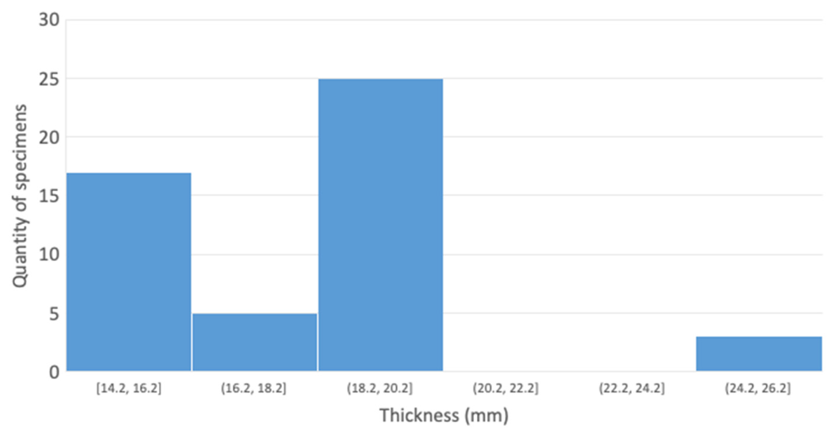
Duplicates of steel plates on a one-legged platform structure in China were adopted for this fatigue testing programme. In addition, extra specimens manufactured using ASTM A537 and A131 steel were conducted with identical tests as the test steel plates for comparison. In-air, CP and FC samples could be found in this programme, with plate thicknesses varying from 18 mm to 25 mm.
  • Maddox et al. [34]
Tests were performed on full-scale pipes or strips cut from such pipes with circumferential girth weld. The pipe thickness was set to be 22 mm.
This study recorded detailed testing conditions, including stress ratio, location of failure, nominal and local stress, etc.
  • Kawasaki Steel Corp. [23]
This programme compared the fatigue performance of high-strength steel (with a yield strength of 600 MPa to 800 MPa) to low-strength steel (with a yield strength of 350 MPa). The geometry of the specimen was T-joint, whilst different treatments such as TIG dressing were adopted and compared to the fatigue performance of the base metal and as-welded joints. Several tests in seawater conditions were performed as well.
The samples of high-strength steel are excluded from the database for consistency of data.
  • Various Studies from Raghava [31] and Murthy [41]
These two PhD theses pulled together a literature review of tubular joints by collecting individual tests conducted by different institutes/personal studies, and also gathered the test data with detailed testing conditions. Data are from:
  • Dijkstra et al. [20];
  • Gibstein [21];
  • Lourenssen et al. [22];
  • Dover et al. [24];
  • Gerald et al. [26];
  • Kerr et al. [27];
  • Zhou et al. [28];
  • SERC-M [31].
Tests using CA loading and VA loading are categorised separately. Loading frequencies, loading modes, load ratios, status of corrosive environment, level of cathodic protection and welding conditions are recorded for each of the individual studies. Thicknesses are relatively low, less than 40 mm.

3.2. Collated Fatigue Database

Following the strict categorisation rules, the database was further filtered for the purpose of evaluating the thickness effect. The characteristics of the database are shown in Table 3.

4. Evaluation of Thickness Effect

Data analysis is performed to investigate how precise the current fatigue standards (DNVGL-RP-C203 [4] taken as the baseline) are, as well as the underlying conservatism contained in the thickness correction equations.
The designed S-N curves are originally derived based on one of the programmes in the literature review, i.e., the Fourth Edition of the HSE Guidance on Fatigue, of which the data entries in the database have a variety of testing conditions, such as R-ratios from 0 to 1 and different load paths. Therefore, the “base curve” without any thickness correction is implicitly covered the variation of the other characteristics. In this study, only the variation of thickness is taken into consideration while processing the fatigue database.

4.1. Analysis Method

The fatigue strength from test, Δ σ t e s t , is compared to predicted corrected fatigue stress Δ σ c based on the DNVGL recommendation [4] (Equation (1)) by applying their logarithmic ratio as follows:
l o g 10 ( Δ σ t e s t Δ σ c ) = l o g 10 ( Δ σ t e s t ) l o g 10 ( Δ σ ) l o g 10 ( t r e f T ) k
The l o g 10 ( Δ σ t e s t ) l o g 10 ( Δ σ ) is presented as the data population and will be treated by statistical analysis for its mean and standard deviations, assuming that Δ σ t e s t has a lognormal distribution. Putting the right side of the above equation in two parts in a graph will provide an easy illustration of the effects of thickness correction, i.e.,   l o g 10 ( Δ σ t e s t ) l o g 10 ( Δ σ ) and l o g 10 ( t r e f T ) k .
Equation (8) may be updated using a revised thickness correction factor formula by changing the effective thickness, as discussed in Section 2.4.
l o g 10 ( Δ σ t e s t Δ σ c ) = l o g 10 ( Δ σ t e s t ) l o g 10 ( Δ σ ) l o g 10 ( t r e f T e f f ) k
These recalculated data points are analysed and presented graphically in the following sections.

4.2. Data Analysis

4.2.1. T-Joints

In Air

The fatigue test database contains data of T-joints for a wide variety of thicknesses, from 16 mm to 200 mm. Those data were allocated to different bins according to their thicknesses and environmental conditions for data analysis.
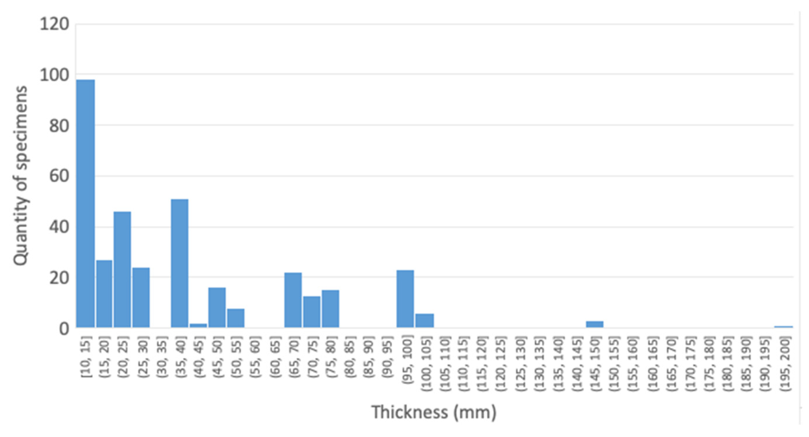
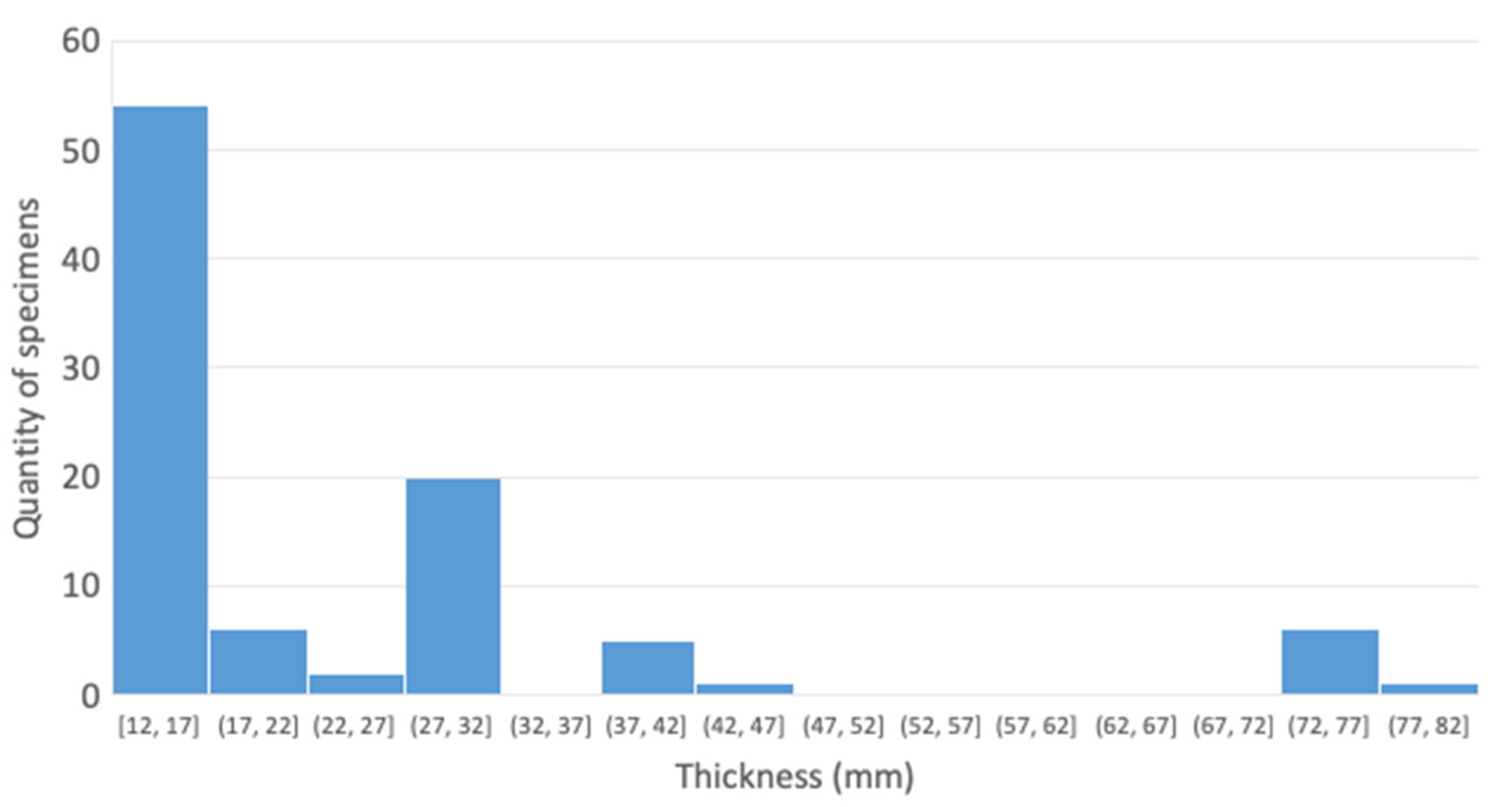
For the in-air condition, a quantity of samples for each thickness range is shown in Figure 5, where most of the samples are less than 40 mm, but there is still a fair amount of samples widely distributed from 40 mm to 200 mm.
The size effect could be considered by changing T to Teff, however, the database lacks details (i.e., attachment length, L) so no further assessment could be made to the existing data due to this restriction. Therefore, T is taken to be Teff in the following analysis.
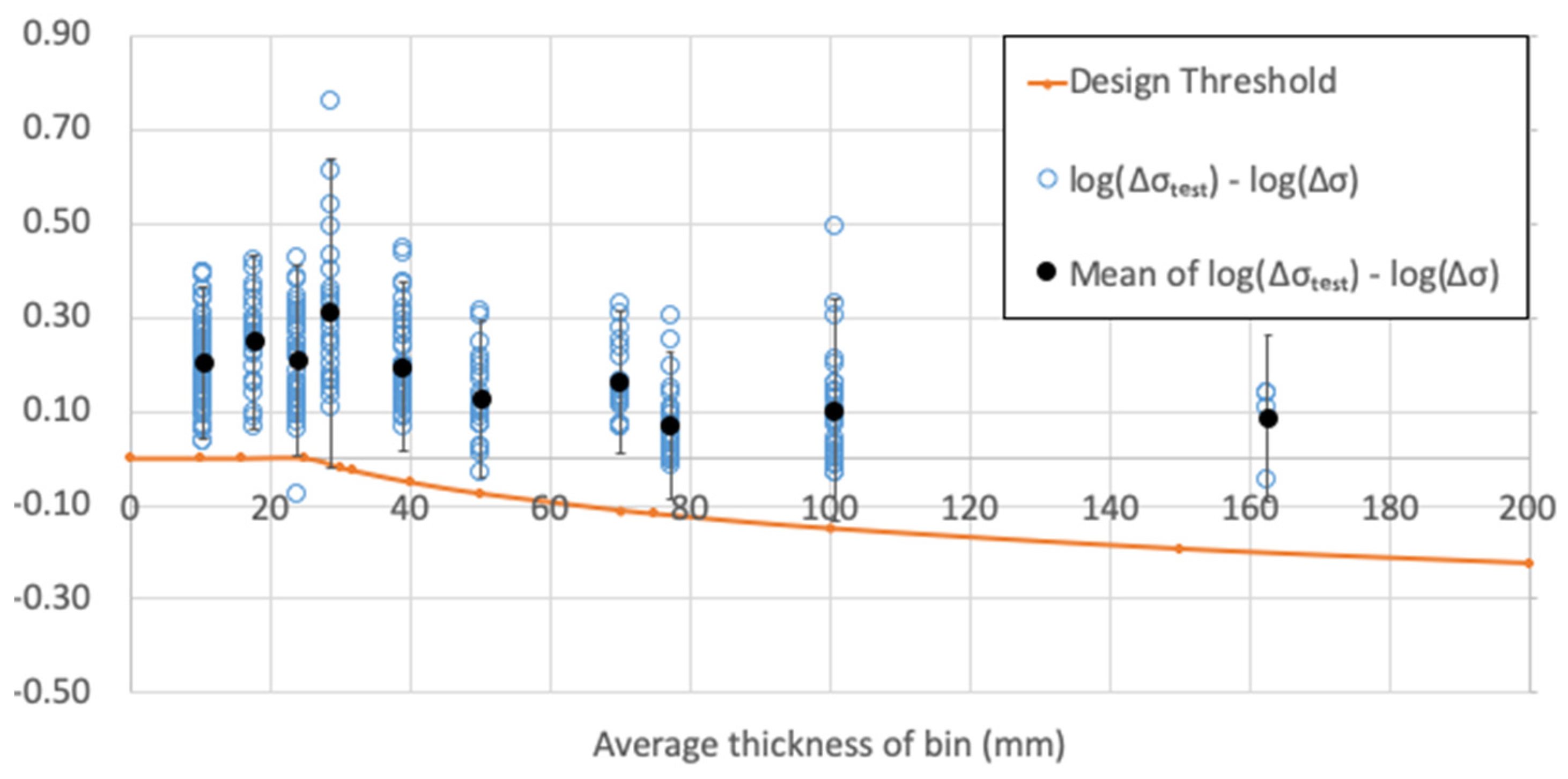
The design fatigue strength Δσc for T-joints was calculated against the DNVGL F curve. Each member of the group is presented with an error bar, of which the upper bound (mean + 2 × standard deviation) and the lower bound (mean – 2 × standard deviation) of the distribution are shown in Figure 6.
In an ideal situation, the design curve should follow the lower bound of the error bars. Otherwise, the gap between the lower bound of the error bars implies that the current standard is within a certain extent of conservatism.
In Figure 6, the blue dots represent l o g 10 ( Δ σ t e s t ) l o g 10 ( Δ σ ) , and the orange line is the thickness correction part of Equation (8), l o g 10 ( t r e f T ) k .
Observations:
  • The mean fatigue strengths start decreasing beyond the reference thickness of 25 mm but appear to level off after 50 mm with increasing thickness;
  • With increasing thickness, the lower bound of test data, corresponding to mean –2 × standard deviation, decreases in general but is higher than the design threshold. Consideration should also be given for the statistical uncertainties due to the lack of data in some data groups;
  • Test data are concentrated in the small thickness range (T <50 mm), but there are still sizable amounts of data in the thickness range greater than 50 mm.

Cathodic Protection

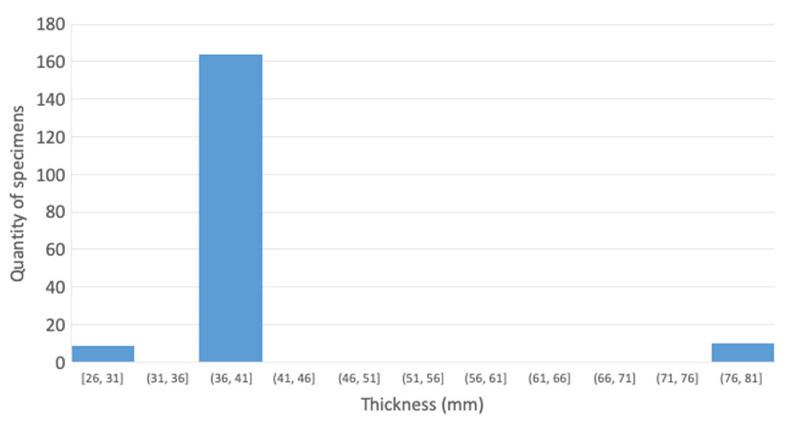
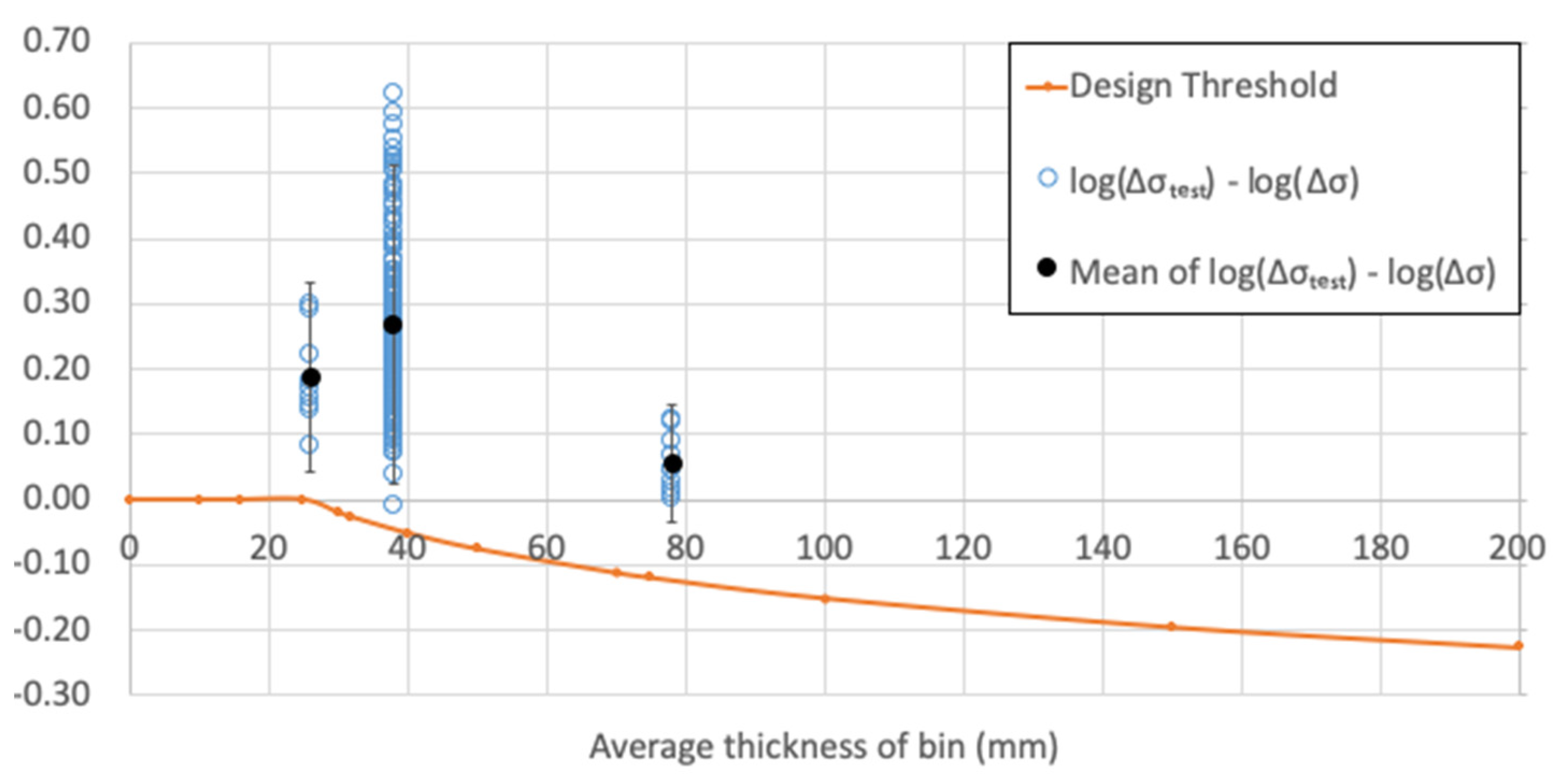
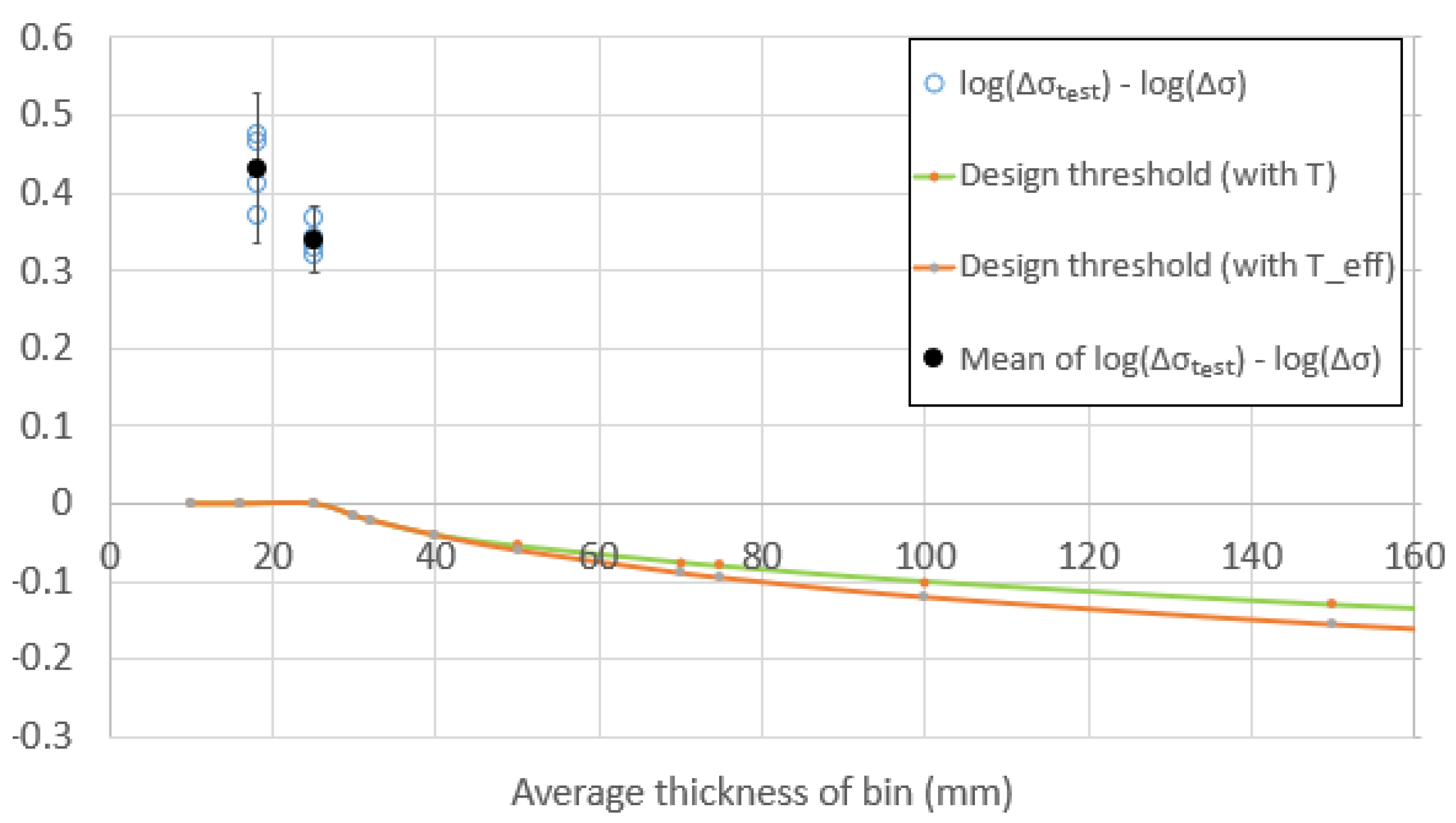
Figure 7 shows the histograms for tests in the CP condition. It can be seen that the data points are concentrated in three bins with markedly little data for T > 41 mm. Data analysis for CP T-joints is presented in Figure 8.
Observations:
  • With increasing thickness, the few data groups do not indicate that the mean fatigue strength follows a monotonic relation. This may imply that the thickness effect may not exist or does not play a dominant role, where other factors may affect the performance to a greater extent compared to the in-air condition;
  • With increasing thickness, the fatigue strength at a lower bound is consistently higher than the design threshold, meaning the design curve is conservative;
  • A lack of test results imposes large uncertainties at the system level as well as the local level in the first group and the third group.

Free Corrosion

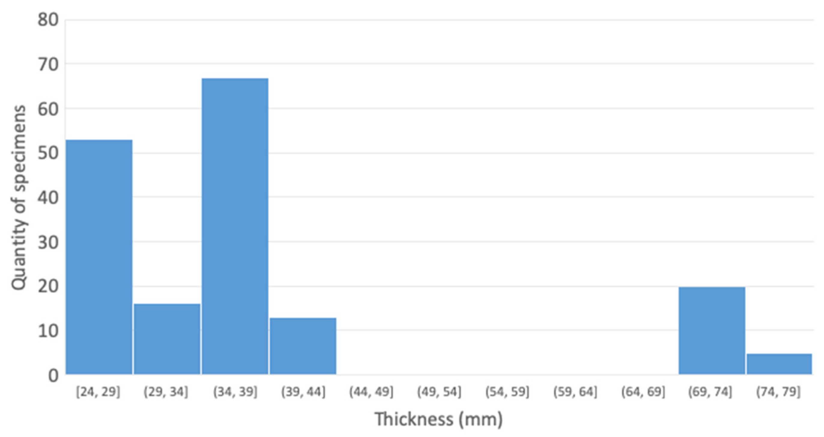
Figure 9 shows the histograms for tests in the FC condition. There is significant amount of data in the T < 44 mm region, but data for T > 44 mm are still limited. Data analysis for FC T-joints is presented in Figure 10.
Observations:
  • With increasing thickness, the mean fatigue strength does not follow a monotonic relation. This may imply that thickness effect may not exist or does not play a dominant role, where other factors may affect the performance to a greater extent compared to the in-air condition;
  • With increasing thickness, the fatigue strength at the lower bound is consistently higher than the design threshold, meaning the design curve is conservative, and much more than that for the in-air condition;
  • A lack of test results imposes large uncertainties in the higher thickness region.

4.2.2. Transverse Butt-Welded Joints

In Air

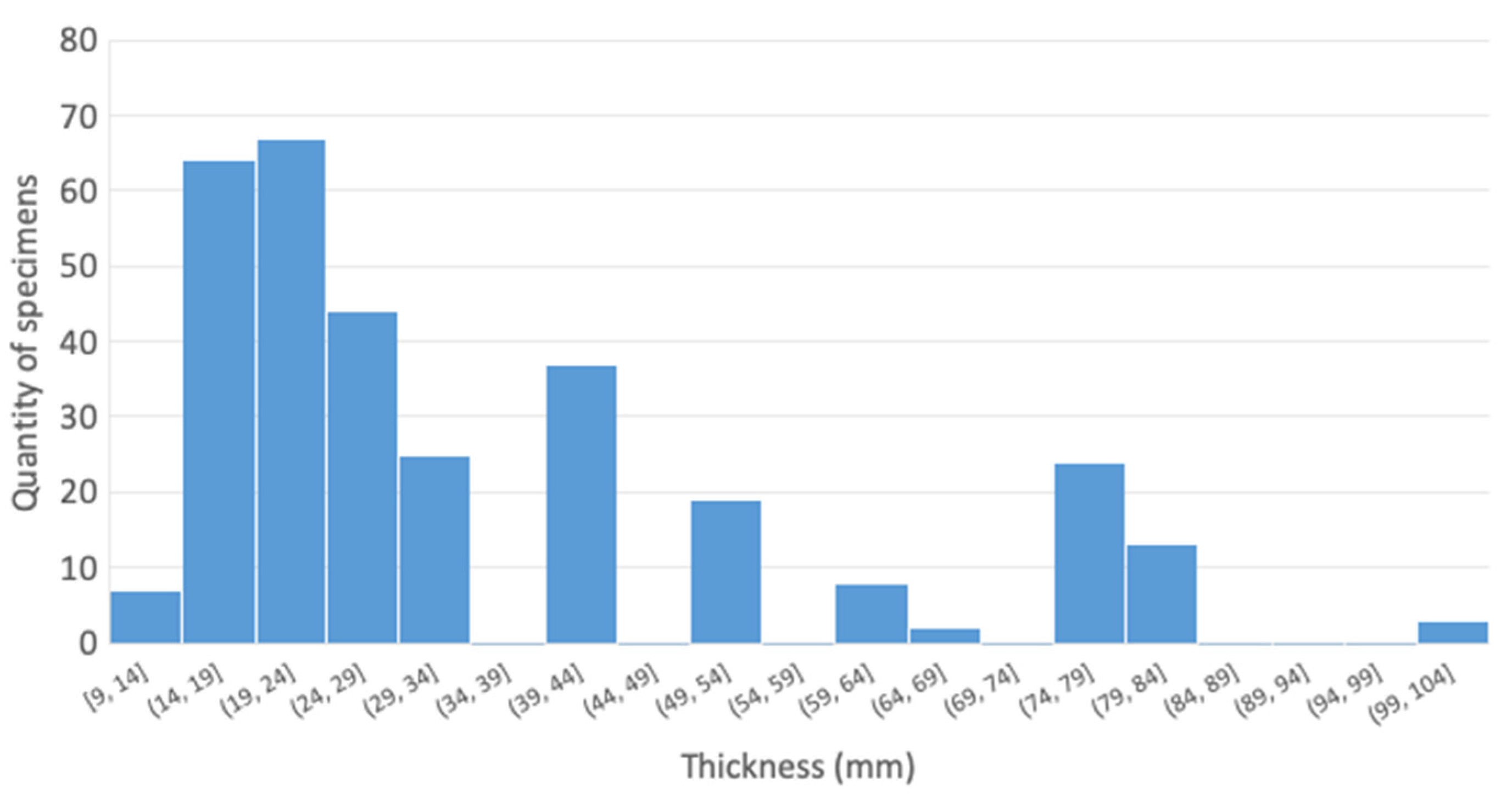
The fatigue test database contains a number of tests with transverse butt-welded joints for thicknesses ranging from 9 to 100 mm. However, most of the data are for the in-air condition, where, in a corrosive environment, tests are all less than or equal to the DNVGL reference thickness (25 mm).
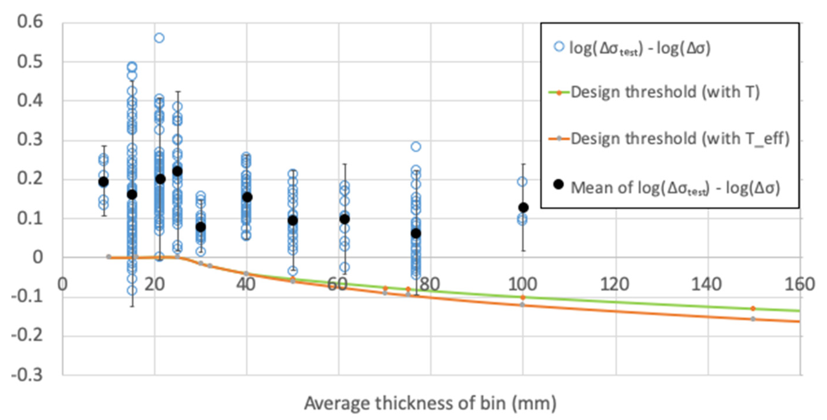
The histogram of thickness for in-air transverse butt-welded joints is presented in Figure 11. There is still fair amount of data in the high thickness region. Data analysis can be found in Figure 12.
Observations:
  • With increasing thickness after the reference thickness, the mean fatigue strengths initially drop but level off after 50 mm;
  • With increasing thickness after the reference thickness, the fatigue strengths at the lower bound are mostly above the design threshold, meaning that the design curve is conservative;
  • Test data are concentrated in the small thickness range (T ≤ 40 mm);
  • As the attachment length (L) for the double-sided transverse butt weld can be taken to be equal to the plate thickness if the weld prep profile is 45°, the effective thickness can be made smaller. Conservatism at a higher thickness can be reduced, as shown by the green line in Figure 12.

Cathodic Protection

In Figure 13, only three samples are equal or greater than the DNVGL reference thickness for transverse butt-welded joints under the CP condition. Thus, limited information can be extracted from the data analysis in Figure 14.
Observations:
  • The mean fatigue strengths increase against the increase in thickness;
  • There is a lack of data in the high thickness region, thus statistical uncertainty may be high.

Free Corrosion

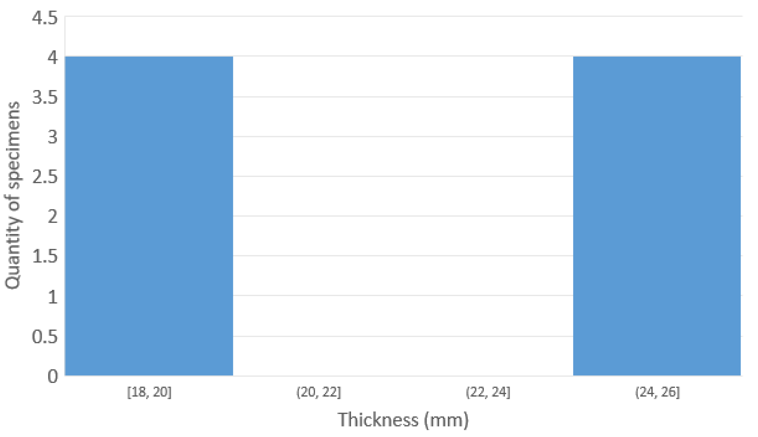
For the FC environment, only eight data entries of transverse butt-welded joints are recorded, as presented in Figure 15, of which four are equal to the DNVGL reference thickness. The data analysis of this exposure category is presented in Figure 16.
Observations:
  • The mean fatigue strengths decrease against the increase in thickness;
  • There is a lack of data in all thickness regions, thus statistical uncertainty may be high.

4.2.3. Tubular Joints

In Air

Similar to the other joint categories, but more controversially, the samples for tubular joints were highly accumulated in the low thickness region. There are some high thickness data for the in-air condition, but very limited data for the corrosive environment.
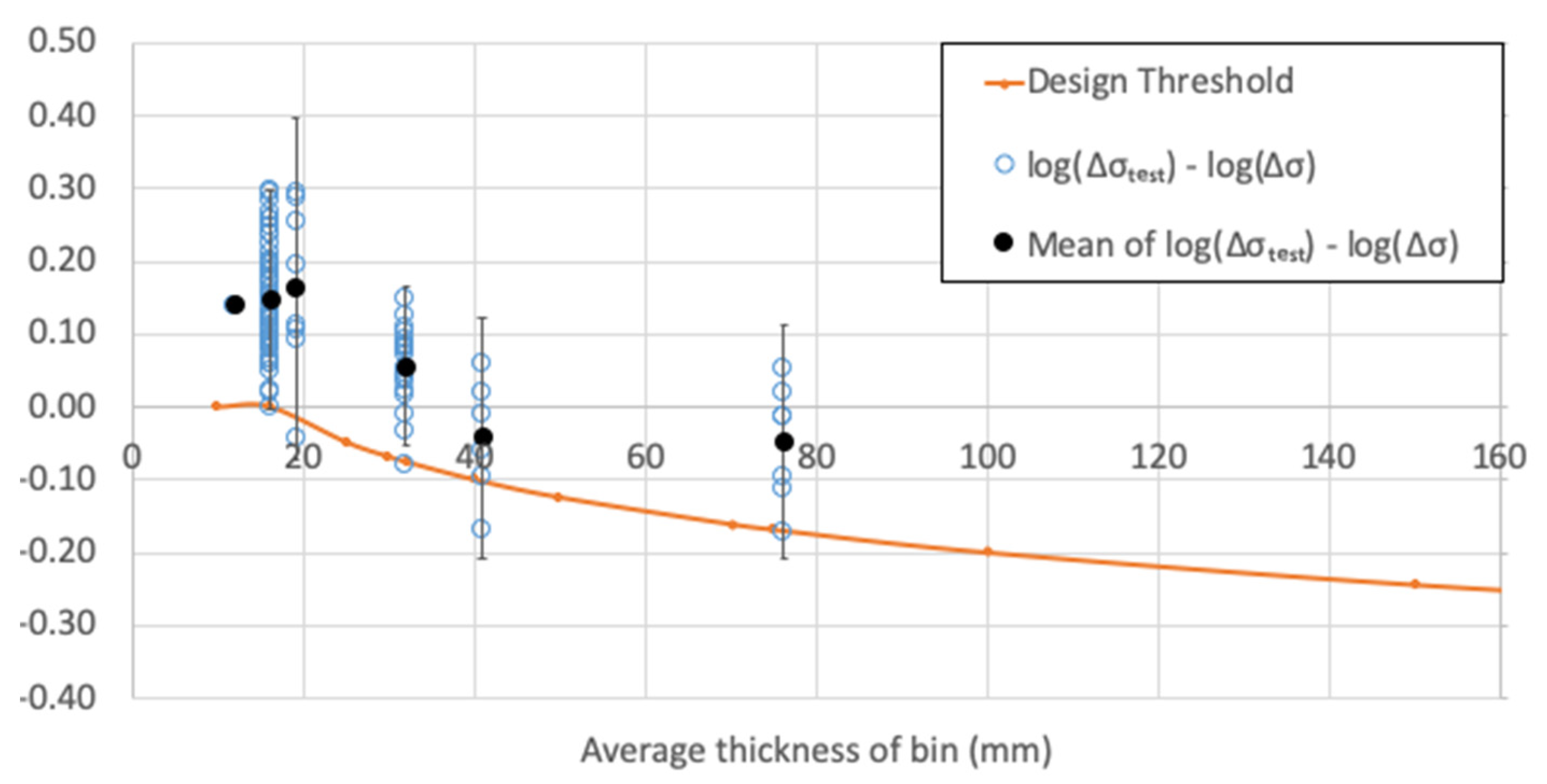
Figure 17 shows the histogram of thickness for the in-air tubular tests. The associated data analysis is presented in Figure 18.
Observations:
  • As the lower bound for some high thickness bins lies below the design threshold, the design curve is not entirely at the conservative side according to these data. This phenomenon may be due to a number of reasons, one of which could be the statistical bias because of lack of data;
  • The mean fatigue strength of the last two groups seemed to level off at the higher thickness range.

Cathodic Protection

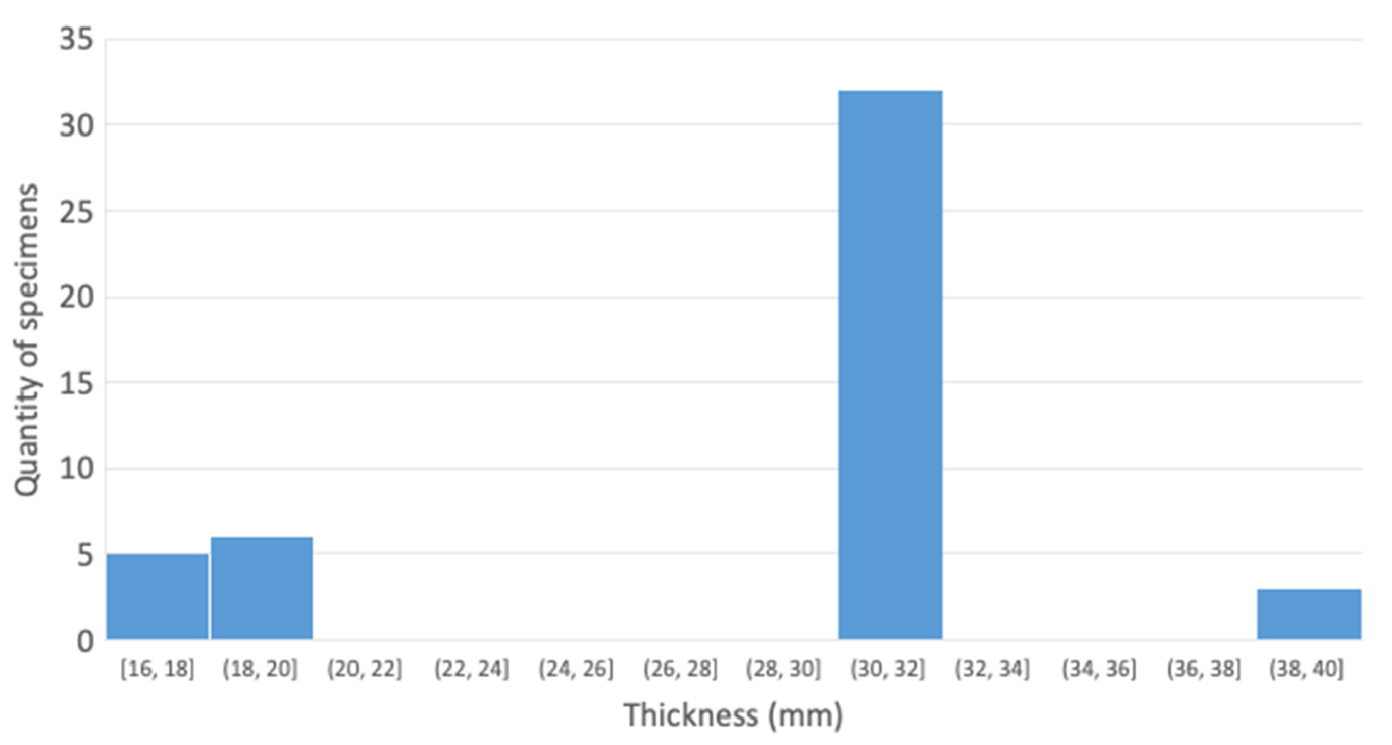
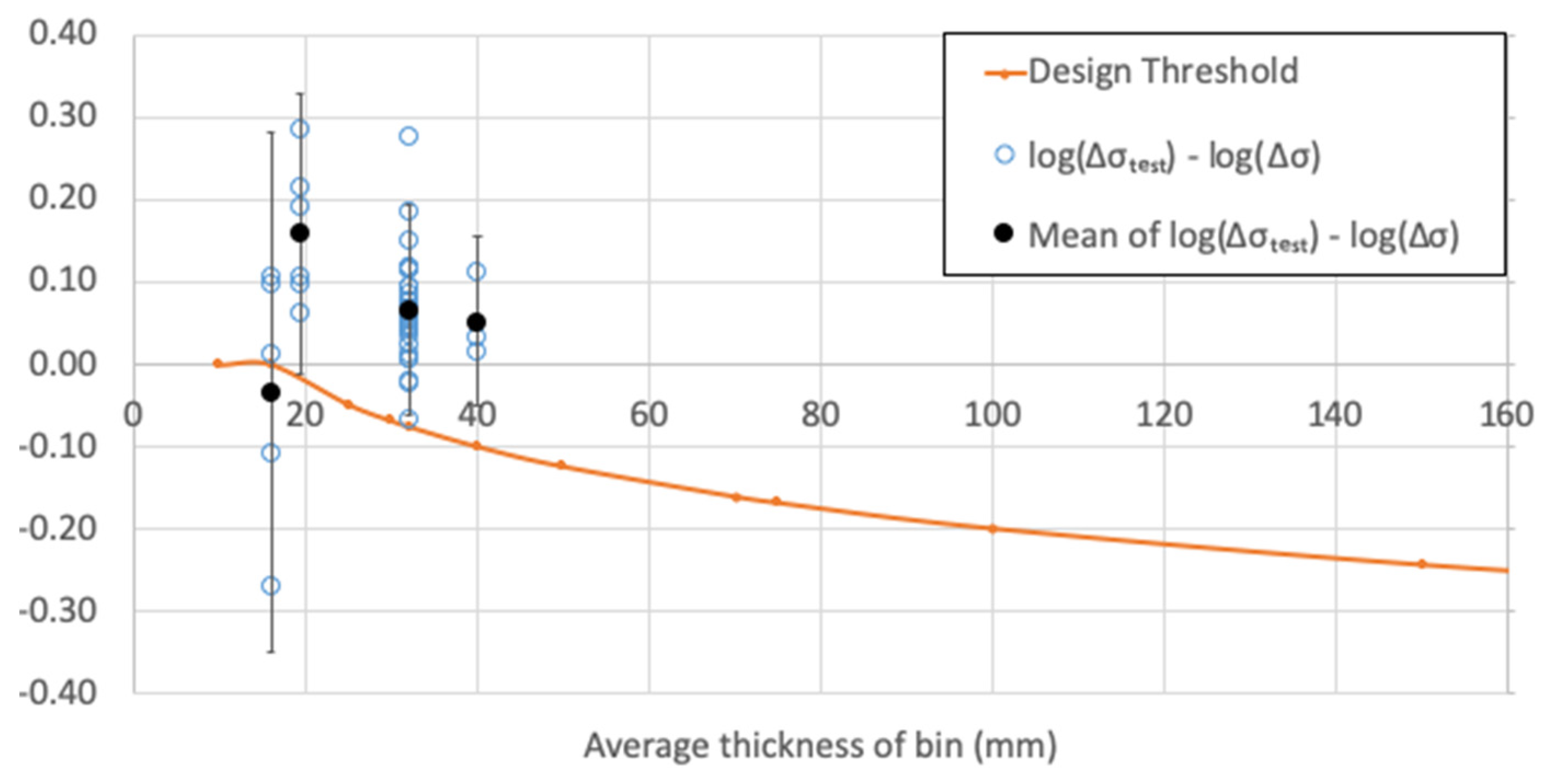
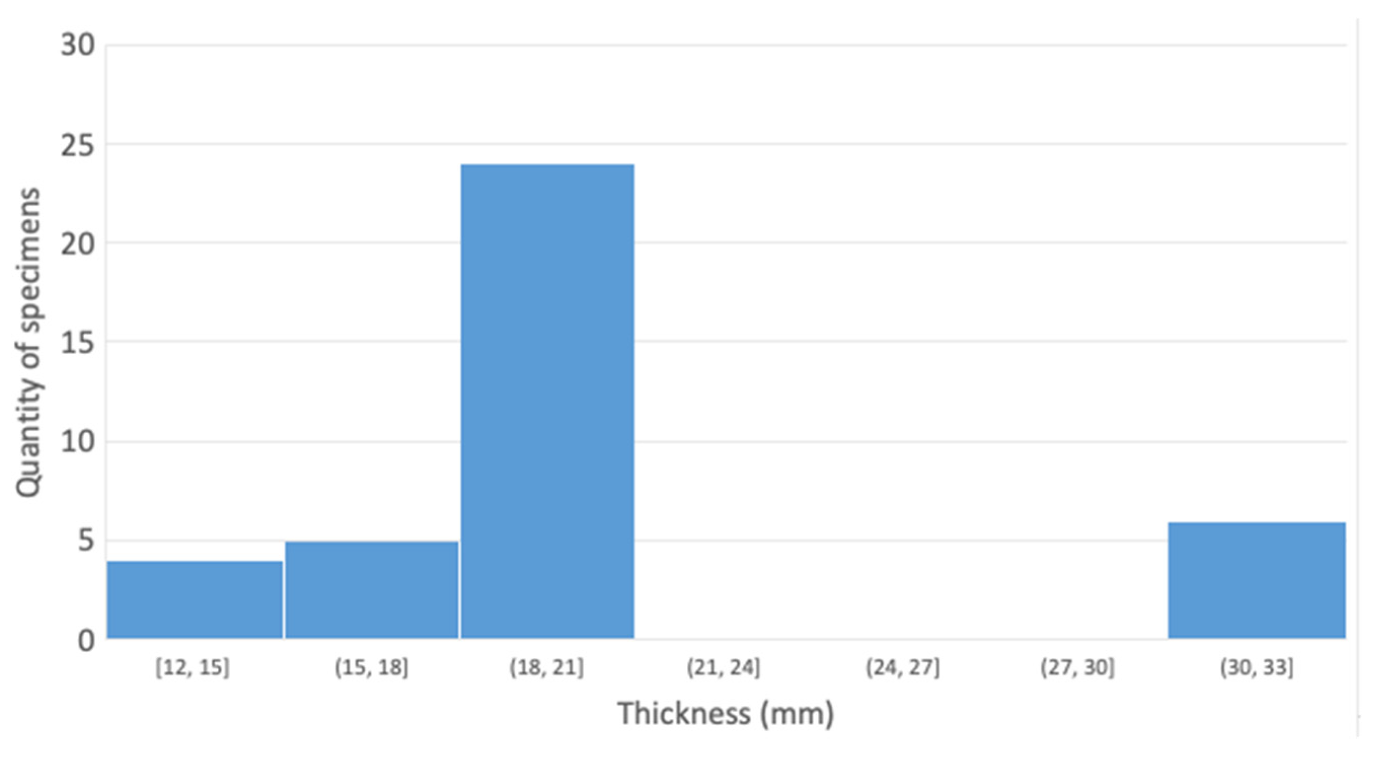
For tubular joints under the CP condition, most of the data are greater than the reference thickness of the DNVGL T curve, which is 16 mm. As illustrated in Figure 19, more than 30 data entries are accumulated in the 32 mm region. Data analysis for CP tubular joints is presented in Figure 20.
Observations:
  • The mean fatigue strengths decrease against the increase in thickness, despite the first bin of data;
  • Except the first bin of data, the lower bound of the rest of the data fits the design threshold quite well before 32 mm, but is slightly conservative after 32 mm. This may be due to the statistical uncertainty of the last bin at 40 mm that contains only three data entries.

Free Corrosion

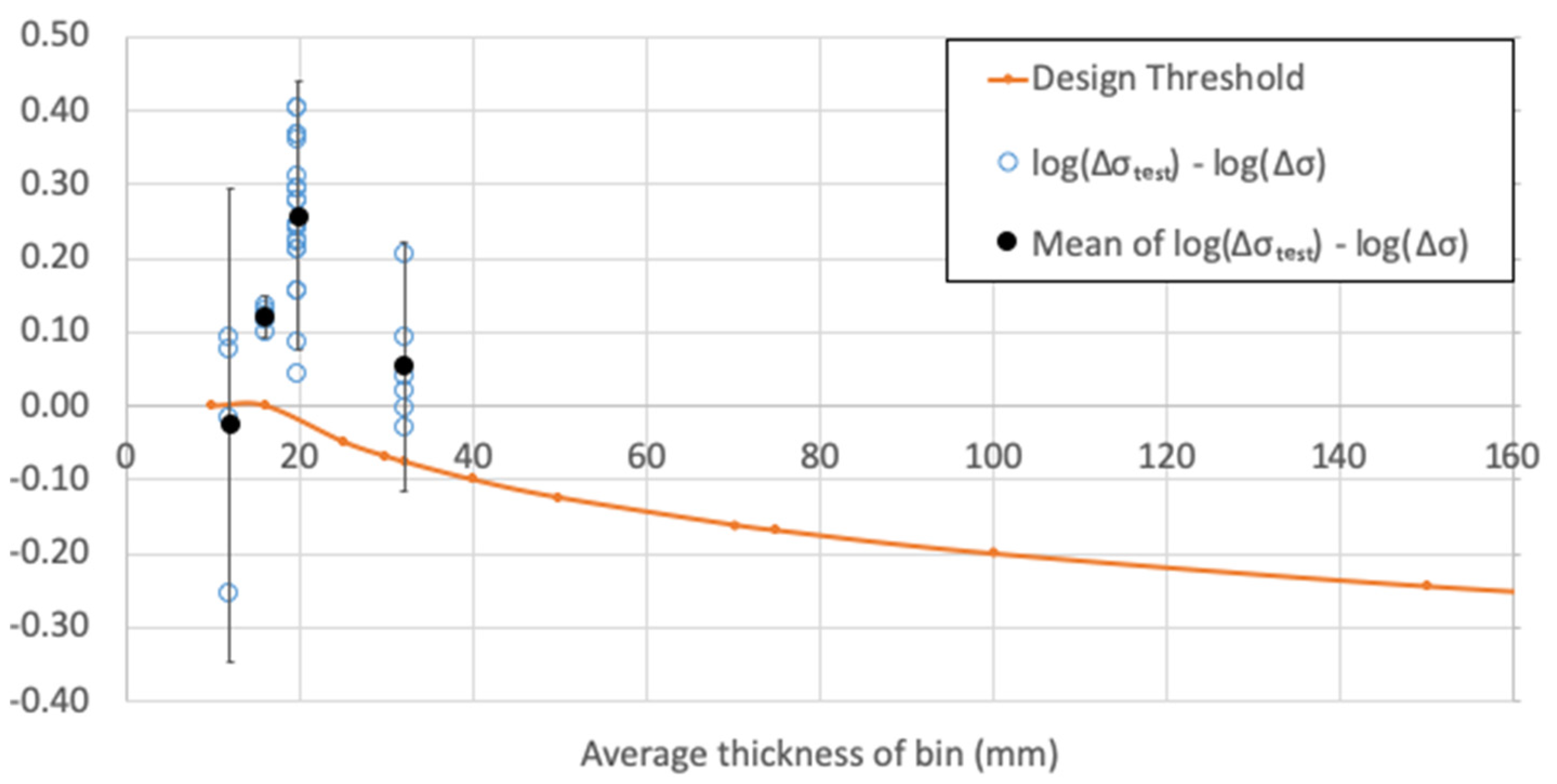
Figure 21 shows the histogram of the thickness distribution for tubular joint data under the FC condition. Most of the data under this exposure are at 20 mm, and a limited amount of data can be found in other ranges. Data analysis for FC tubular joints is presented in Figure 22.
Observations:
  • Most of the data entries fall above the design threshold, despite the first bin of data at 12 mm, which has a larger dispersion. This phenomenon could be induced by the outlier data entries;
  • There is a lack of data in most thickness regions, especially for higher thicknesses.

5. Discussion

For T-joints, the following summary can be made:
  • The decrease in fatigue strength is less severe than predicted using the general thickness correction factor when the thickness is greater than 40 mm in a non-corrosive environment. This trend appears to agree with the proposed modification in the latest DNVGL-RP-C203 [4], as shown in the recent work by Lotsberg [13] which modifies this formula to consider the size effect. However, the size effect equation cannot be used for evaluation with the current test dataset because of a lack of information on the additional dimensions, such as the attachment length L in the original test conditions;
  • For the limited data available for corrosion fatigue tests, analysis shows the current standards are on the conservative side, but with varying degrees of conservatism in different thickness ranges. This phenomenon can be attributed to the following:
    Statistical uncertainties due to the number of the data points;
    There are multiple factors affecting corrosion fatigue in each of the different tests, hence greater scatter. A cleaned data base with uniform attributes may help, but the quantity of data will be significantly reduced for each of the groups;
    The non-proportional aspect of corrosion fatigue may be dominant which diminishes the effects of thickness.
For transverse butt-welded joints, the following summary can be made:
  • The mean fatigue strength levels off when thickness is greater than 40 mm in a non-corrosive environment;
  • Although there is high statistical uncertainty due to a lack of data for thicker specimens, fatigue strength based on this database gives slightly less conservative values than the current standard in a non-corrosive environment,
  • The size effect equation can improve the design standard, especially for high-thickness transverse butt-welded joints;
  • Due to a lack of corrosion fatigue data, a more quantitative thickness effect cannot be illustrated, but most of the existing data are on the conservative side.
For tubular joint, the data are much scarcer. Given the statistical uncertainties, the following summary can be made:
  • The mean fatigue strength decreases with increasing thickness for in-air and CP conditions, supporting the theory of fatigue strength reduction with increasing thickness.
  • The fatigue strength characteristic values based on the in-air samples are close to the design strength from standards.
  • There is wide variation of data spread for fatigue in a corrosive environment from the available limited data points.

6. Conclusions

Thickness effects have been observed from early fatigue tests and have been considered in design standards in various forms. The work in this study is to re-evaluate the suitability of current standards in regard to the thickness effect. The study has concentrated on T-joints, transverse butt-welded joints and tubular joints, as these are the most commonly used joint types in the offshore wind industry and in the offshore oil and gas industry, and most of the experiments are conducted on these types.
A large database with research work over the last 40 years has been collected by the authors. This database has been sanitised for its integrity and relevance to the design of S-N curves of those welding joint details.
Statistical analysis of the fatigue strength S for each of the thickness ranges has been conducted and compared to thickness correction values recommended by DNVGL-RP-C203 [4]. The following agreement and major differences have been found:
  • There is good agreement of thickness correction factors between the DNVGL-RP-C203 values and the characteristic values, defined as the mean + 2 standard deviation, obtained from data analysis for in-air conditions, for T-joints and transverse butt-welded joints with thicknesses up to 100 mm. Further extrapolation beyond 100 mm will yield conservative results. However, only two groups of data are available with t > 100 mm.
  • For corrosion fatigue with CP for T-joints and transverse butt-welded joints, the thickness correction factors in DNVGL-RP-C203 are generally conservative even with relatively thin thicknesses of t = 25 mm. Even greater conservatism has been found for the FC condition for these joint types. It is therefore inferred that the thickness correction effects are overestimated in current standards for the corrosive fatigue predictions.
  • For tubular joints and for in-air conditions, the data follow the trend of a decrease in mean fatigue strength with increasing thickness, though the agreement with design values is less when the dispersion is considered. For corrosion fatigue when t > 16 mm, though the prediction is generally conservative, the agreement between design values and data is even poorer. There is high level of statistical uncertainties due to a lack of sufficient data.
This research has presented fatigue data and observations from the statistical analysis but also pinpointed areas where there are not sufficient data. These are, in general, for corrosive environments, for large thicknesses and for special joints such as tubular joints. The analysis for T-joints with a relatively large database shows significant conservatism in corrosion fatigue prediction. It can be expected that an enlarged database will demonstrate this conservatism for other type of joints with greater thicknesses (t > 40 mm) and in corrosive environments. This study can be used to point towards directions for future research, as fatigue tests require significant investment to plug the gaps.

Author Contributions

Conceptualization, W.Z.; Data curation, W.Z. and W.-T.H.; Formal analysis, W.-T.H.; Investigation, W.Z., W.-T.H.; Methodology, W.Z.; Supervision, W.Z.; Validation, W.Z.; Writing—original draft, W.-T.H.; Writing—review & editing, W.Z. All authors have read and agreed to the published version of the manuscript.

Funding

The fatigue test database was collated by ODE. The analysis of this database was funded by the Bureau of Ocean Energy Management (BOEM), U.S. Department of the Interior, Washington, D.C., under Contract 140M0119C0010.

Acknowledgments

Part of this study was funded by the Bureau of Ocean Energy Management (BOEM), U.S. Department of the Interior, Washington, D.C., under Contract 140M0119C0010. The fatigue test database was collated by ODE outside the project.

Conflicts of Interest

The authors declare no conflict of interest. The funders had no role in the design of the study; in the collection, analyses, or interpretation of data; in the writing of the manuscript, or in the decision to publish the results.

Abbreviations

ABSAmerican Bureau of Shipping
APIAmerican Petroleum Institute
ASTMAmerican Society for Testing and Materials
CAConstant Amplitude
CPCathodic Protection
DNVGLDet Norske Veritas Germanischer Lloyd
FCFree Corrosion
FCAWFlux-cored Arc Welding
HSEHealth and Safety Executive (UK)
IACSInternational Association of Classification Societies
IIWInternational Institute of Welding
N/ANot Available
OWTOffshore Wind Turbine
PWHTPost-Weld Heat Treatment
SAWSubmerged Arc Welding
S-NStress Range—Number of Cycles
TIGGas Tungsten Arc Welding
TWIThe Welding Institute
UCLUniversity College London
UKOSRPUK Offshore Steels Research Project
VAVariable Amplitude

References

  1. Zhao, W. Structural Reliability of Fatigue and Fracture under Random Loading. Ph.D. Thesis, University of London, London, UK, 1989. [Google Scholar]
  2. Sørensen, J. Reliability assessment of wind turbines. In Proceedings of the 12th International Conference on Applications of Statistics and Probability in Civil Engineering, Vancouver, CA, USA, 12–15 July 2015. [Google Scholar] [CrossRef]
  3. Zhao, W.; Stacey, A.; Prakash, P. probabilistic models of uncertainties in fatigue and fracture reliability analysis. In Proceedings of the 21st International Conference on Offshore Mechanics and Arctic Engineering, Oslo, Norway, 23–28 June 2002; Volume 3. [Google Scholar] [CrossRef]
  4. DNVGL. (DNVGL-RP-C203). Fatigue Design of Offshore Steel Structures; Det Norske Veritas: Oslo, Norway, 2020. [Google Scholar]
  5. Gurney, T.R. Fatigue of Welded Structures, 2nd ed.; Cambridge University Press: Cambridge, UK, 1979. [Google Scholar]
  6. IIW. Recommendations for Fatigue Design of Welded Joints and Components, IIW-1823-07; International Institute of Welding: Paris, France, 2008. [Google Scholar]
  7. ISO. Petroleum and Natural Gas Industries- Fixed Steel Offshore Structures (ISO 19902); International Organization for Standardization (ISO): Geneva, Switzerland, 2007. [Google Scholar]
  8. Pedersen, M.M. Thickness effect in fatigue of welded butt joints: A review of experimental works. Int. J. Steel Struct. 2019, 19, 1930–1938. [Google Scholar] [CrossRef]
  9. API. API Recommended Practice: Recommended Practice for Planning, Designing, and Constructing Fixed Offshore Platforms–Load and Resistance Factor Design (API-RP-2A-LRFD); American Petroleum Institute (API): Washington, DC, USA, 2019. [Google Scholar]
  10. ABS. Guide for Fatigue Assessment of Offshore Structures (ABS-115); American Bureau of Shipping (ABS): Houston, TX, USA, 2020. [Google Scholar]
  11. Gurney, T.R. The influence of thickness on fatigue of welded joints-10years on (a review of British work). In Proceedings of the 8th International Conference on Offshore Mechanics and Arctic Engineering, The Hague, The Netherlands, 19–23 March 1989; Volume III, pp. 1–8. [Google Scholar]
  12. International Association of Classification Societies (IACS). Harmonized Common Structural Rules for Oil Tankers and Bulk Carriers; IACS: London, UK, 2014. [Google Scholar]
  13. Lotsberg, I. Assessment of the size effect for use in design standards for fatigue analysis. Int. J. Fatigue 2014, 66, 86–100. [Google Scholar] [CrossRef]
  14. Haagensen, P.J. Influence of Notch Severity on Size Effects in Welded Joints and Notched Components. In Proceedings of the International Conference of Weld Failures (Weldtech 88), London, UK, 21–24 November 1988. [Google Scholar]
  15. Berge, S. On the effect of plate thickness in fatigue of welds. Eng. Fract. Mech. 1985, 21, 423–435. [Google Scholar] [CrossRef]
  16. Cole, I.S.; Vittori, O.; Cerretti, G. Cathodic protection and thickness effect: A final conclusion. In Proceedings of the 3rd Offshore and Polar Engineering Conference, Singapore, 6–11 June 1993; pp. 309–316. [Google Scholar]
  17. OTO 99 058. Fatigue Design Curves for Welded Joints in Air & Seawater Under Variable Amplitude Loading; Health and Safety Executive (HSE): Bootle, Merseyside, UK, 2000. [Google Scholar]
  18. Vaessen, G.; de Back, J.; van Leeuwen, J. fatigue behavior of welded steel joints in air and seawater. J. Pet. Technol. 1982, 34, 440–446. [Google Scholar] [CrossRef]
  19. OTH 92 392. A Survey of Some Recent Corrosion Fatigue Tests on Welded Joints in Steel Plate; Health and Safety Executive (HSE): Bootle, Merseyside, UK, 1994. [Google Scholar]
  20. Dijkstra, O.D.; de Back, J. Fatigue strength of Tubular T- and X-Joints. In Proceedings of the Offshore Technology Conference, Houston, TX, USA, 5–8 May 1980. [Google Scholar] [CrossRef]
  21. Gibstein, M.B. Fatigue strength of welded tubular joints tested at Det norske Veritas laboratories. In Proceedings of the Conference on Steel in Marine Structures, Paris, France, 5–8 October 1981. Paper No 8.4. [Google Scholar]
  22. Lourenssen, A.A.; Dijkstra, O.D. Fatigue tests on large post weld heat treated and as welded tubular T-Joints. In Proceedings of the Offshore Technology Conference, Houston, TX, USA, 3–6 May 1982. [Google Scholar] [CrossRef]
  23. Narumoto, A.; Akahide, K.; Kikukawa, S.; Kawai, Y.; Hashimoto, O. Corrosion fatigue strength of high-strength low alloy steels for offshore structures. In Proceedings of the Offshore Technology Conference, Houston, TX, USA, 6–9 May 1985. [Google Scholar] [CrossRef]
  24. Dover, W.D.; Wilson, T.J. Corrosion Fatigue of Tubular Welded Joints. Advances in Fracture Research, Proceedings of the Sixth International Conference on Fracture ICF6; Valluri, S.R., Ed.; Pergamon Press: New Delhi, India, 1984; pp. 2505–2512. [Google Scholar]
  25. Vosikovosky, O.; Bell, R.; Burns, D.J.; Monaupt, U.H. Effects of Cathodic Protection and Thickness on Corrosion Fatigue Life of Welded Plate T-Joints. In Proceedings of the Conference on Steels in Marine Structures, Delft, The Netherlands, 15–18 June 1987. [Google Scholar]
  26. Gerald, J.; Bignonnet, A.; Lieurade, H.P.; Lecoq, H. Corrosion Fatigue Tests on High Strength Steel Tubular X Nodes with Improved Welds. In Steel in Marine Structures, Proceedings of the third International ECSC Offshore Conference on Steel in Marine Structures (SIMS ‘87), Delft, The Netherlands, 15–18 June 1987; Elsevier Science Publishers: Amsterdam, The Netherlands, 1987; pp. 455–463. [Google Scholar]
  27. Kerr, J.; Holmes, R.; Brown, G.M. Fatigue of Large Tubular Joints Subjected to Cathodic Protection. In Steel in Marine Structures, Proceedings of the third International ECSC Offshore Conference on Steel in Marine Structures (SIMS ’87), Delft, The Netherlands, June 1987; Elsevier Science Publishers: Amsterdam, The Netherlands, 1987; pp. 479–487. [Google Scholar]
  28. Zhou, M.; Yao, M.; Shi, L. Improvement of Fatigue Strength of Tubular T Joint in Offshore Platforms Due to Postweld Treatment; China Ocean Engineering, China Ocean Press: Shanghai, China, 1990; Volume 4, pp. 189–198. [Google Scholar]
  29. Ohta, A.; Mawari, T.; Suzuki, N. Evaluation of effect of plate thickness on fatigue strength of butt welded joints by a test maintaining maximum stress at yield strength. Eng. Fract. Mech. 1990, 37, 987–993. [Google Scholar] [CrossRef]
  30. OTH 92 390. Background to New Fatigue Guidance for Steel Joints and Connections in Offshore Structures; OTH 92 390; Health and Safety Executive (HSE): Bootle, Merseyside, UK, 1999. [Google Scholar]
  31. Raghava, G. Corrosion Fatigue Behaviour of Cathodically Protected Stiffened Steel Tubular T Joints. Ph.D. Thesis, Anna University, Chennai, India, 1998. [Google Scholar]
  32. Huang, X.; Wang, Z. Durability method on corrosion fatigue performance of AH 32 steel. Frat. Integrità Strutt. 2019, 13, 481–490. [Google Scholar] [CrossRef]
  33. Lee, J.K.; Yoon, T.Y.; Chang, S.P. The fatigue performance of buttwelded joint with thick plates. Res. Inst. Ind. Sci. Technol. 2003, 17, 249–255. [Google Scholar]
  34. Li, Y.; Hou, B. Corrosion fatigue of welded joints of steel for marine platform. Indian J. Eng. Mater. Sci. 2006, 13, 467–470. [Google Scholar]
  35. Maddox, S.J.; Zhang, Y. Comparison of fatigue of girth-welds in full-scale pipes and small-scale strip specimens. In Proceedings of the 27th International Conference on Offshore Mechanics and Arctic Engineering, Estoril, Portugal, 15–20 June 2008. [Google Scholar] [CrossRef]
  36. Kim, K.N.; Lee, S.H.; Jung, K.S. Evaluation of factors affecting the fatigue behaviour of butt welded joints using SM520C-TMC steel. Int. J. Steel Struct. 2009, 9, 185–193. [Google Scholar] [CrossRef]
  37. Polezhayeva, H.; Badger, C. Effect of plate thickness on fatigue strength of base material and butt welded specimens made from EH40 steel thick plates: Phase 1. In Proceedings of the Nineteenth International Offshore and Polar Engineering Conference (ISOPE), Osaka, Japan, 21–26 June 2009; pp. 366–373. [Google Scholar]
  38. EUR 24214. Fatigue Behaviour of High-Strength Steel-Welded Joints in Offshore and Marine Systems; EUR 24214: Luxembourg, 2010. [Google Scholar]
  39. Olafsson, O.M. Improved Design Basis of Welded Joints in Seawater. Ph.D. Thesis, Technical University of Denmark, Lyngby, Denmark, 2016. [Google Scholar]
  40. Kang, S.K. Thickness Effect of Fatigue on butt weld joints. In Proceedings of the TSCF 2016 Shipbuilders Meeting, Korean Register, Busan, Korea, 26–27 October 2016. [Google Scholar]
  41. Murthy, D.S.R. Corrosion Fatigue Behaviour of Steel Tubular Joints of Offshore Structures. Ph.D. Thesis, Anna University, Madras, India, 1993. [Google Scholar]
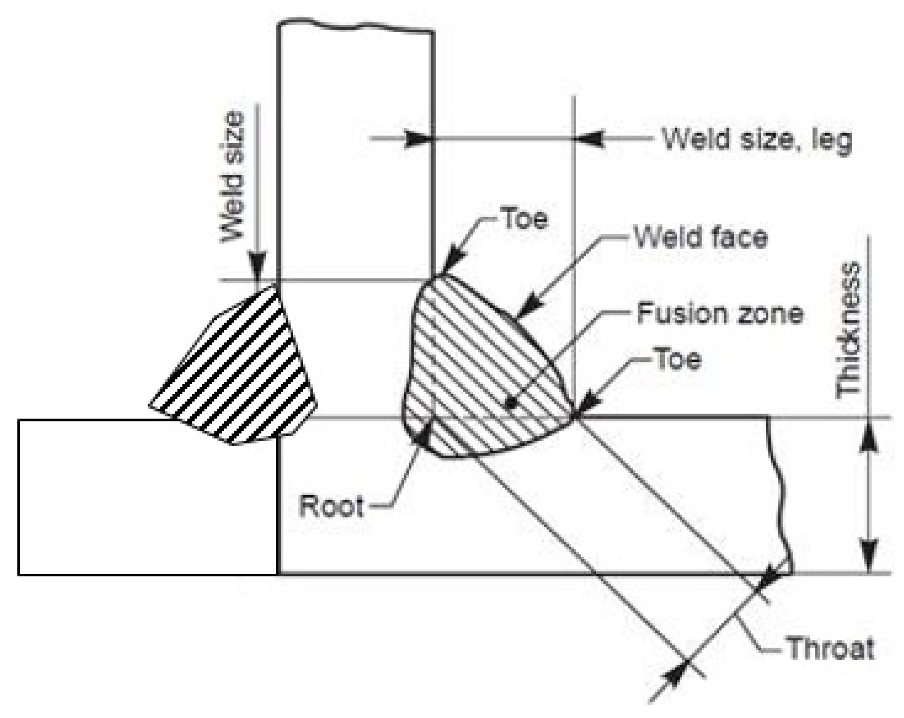
Figure 1. Weld detail of a T-joint with fillet weld.
Jmse 08 00895 g001
Figure 2. Weld detail of transverse butt-welded joint.
Jmse 08 00895 g002
Figure 3. Layout of tubular joint.
Jmse 08 00895 g003
Figure 4. Definition of attachment length in cruciform joints and weld width in butt welds [4].
Jmse 08 00895 g004
Figure 5. Histogram of thickness with in-air T-joint samples.
Jmse 08 00895 g005
Figure 6. Data analysis of in-air T-joints.
Jmse 08 00895 g006
Figure 7. Histogram of thickness with CP T-joint samples.
Jmse 08 00895 g007
Figure 8. Data analysis of CP T-joints.
Jmse 08 00895 g008
Figure 9. Histogram of thickness with FC T-joint samples.
Jmse 08 00895 g009
Figure 10. Data analysis of FC T-joints.
Jmse 08 00895 g010
Figure 11. Histogram of thickness with in-air transverse butt-welded joint samples.
Jmse 08 00895 g011
Figure 12. Data analysis of in-air transverse butt-welded joints.
Jmse 08 00895 g012
Figure 13. Histogram of thickness with CP transverse butt-welded joint samples.
Jmse 08 00895 g013
Figure 14. Data analysis of CP transverse butt-welded joints.
Jmse 08 00895 g014
Figure 15. Histogram of thickness with FC transverse butt-welded joint samples.
Jmse 08 00895 g015
Figure 16. Data analysis of FC transverse butt-welded joints.
Jmse 08 00895 g016
Figure 17. Histogram of thickness with in-air tubular joint samples.
Jmse 08 00895 g017
Figure 18. Data analysis of in-air tubular joints.
Jmse 08 00895 g018
Figure 19. Histogram of thickness with CP tubular joint samples.
Jmse 08 00895 g019
Figure 20. Data analysis of tubular joint with CP.
Jmse 08 00895 g020
Figure 21. Histogram of thickness with FC tubular joint samples.
Jmse 08 00895 g021
Figure 22. Data analysis of FC tubular joints.
Jmse 08 00895 g022
Table 1. Reference thickness and power exponent in various standards.
StandardF CurveD CurveT Curve
tref (mm)ktref (mm)ktref (mm)k
DNVGL-RP-C203 [4]250.25250.2160.25
API-RP-2A [7]N/AN/AN/AN/A160.25
ISO 19902 [6]160.25160.25160.25
ABS 115 [10]220.25220.25320.25
Table 2. Source list of fatigue test database.
Programme NameJoint TypeCP ConditionNumber of CA TestsYear
US Highway [17]T-jointIn-air711974–1993
Vaessen et al. [18]T-jointIn-air/FC75 (In-air: 42, FC: 33)1979
UKOSRP I [19]T-jointCP/FC71 (CP: 32, FC: 39)1980
Dijkstra and de Back [20]TubularCP/FC4 (CP: 1, FC: 4)1980
Gibstein [21]TubularCP21981
Lourenssen et al. [22]TubularFC21982
Kawasaki Steel Corp. [23]T-jointIn-air/FC32 (In-air: 16, FC: 16)1985
UKOSRP II [19]T-JointIn-air/CP/FC176 (In-air: 16, CP: 132, FC: 28)1986
Dover et al. [24]TubularCP41986
University of Waterloo [25]T-jointCP/FC30 (CP: 20, FC: 10)1987
Gerald et al. [26]TubularCP21987
Kerr et al. [27]TubularCP41987
Zhou et al. [28]TubularFC41990
Ohta et al. [29]Transverse butt-welded jointIn-air161990
TWI/SINTEF [17]TubularIn-air/CP14 (In-air:8, CP: 6)1993
Nordic Program [17]T-jointIn-air351993
HSE RPFG [30]T-jointIn-air1461995
HSE RPFG [30]TubularIn-air/FC120 (In-air: 94, FC: 26)1995
SERC-M [31]TubularIn-air, FC5 (In-air: 1, FC: 4)N/A
Huang et al. [32]T-jointIn-air/CP77 (In-air: 29, CP: 48)2006
Lee et al. [33]Transverse butt-welded jointIn-air112003
Li et al. [34]Transverse butt-welded jointIn-air/CP/FC29 (In-air: 7, CP: 14, FC: 8)2006
Maddox et al. [35]Transverse butt-welded jointIn-air342008
Kim et al. [36]Transverse butt-welded jointIn-air342009
Polezhayeva et al. [37]Transverse butt-welded jointIn-air72009
FATHOMS [38]Transverse butt-welded jointIn-air/CP78 (In-air: 52, CP: 17)2010
Olafsson [39]Transverse butt-welded jointIn-air/CP108 (In-air: 89, CP: 19)2016
Kang [40]Transverse butt-welded jointIn-air542016
Table 3. Testing characteristics of the fatigue database.
Programme NameThickness (mm)TreatmentLoading Frequency (Hz)R-Ratio
US Highway [17]10As weldedN/AN/A
Vaessen et al. [18]40, 70As welded/PWHT/Ground/Plasma dressed/TIGIn air: 5
Seawater: 0.2
−1/0/0.1
UKOSRP I [19]38As welded/PWHT/Ground/Plasma dressed/TIGIn air: 5
Seawater: 0.17
−1/0
Dijkstra and de Back [20]16, 32As welded0.2−1/0
Gibstein [21]16As weldedN/A−1
Lourenssen et al. [22]32As welded/PWHT0.20
Kawasaki Steel Corp. [23]30As welded/TIG0.167N/A
UKOSRP II [19]38As welded/PWHT/Epoxy coated/Toe ground/Hammer peened/Shot peenedIn air: 5
Seawater: 0.17
−1/−0.5/0/0.5
Dover et al. [24]16As welded0.170.1/0.3
University of Waterloo [25]26, 78As welded0.20.05
Gerald et al. [26]40As welded0.50.1
Kerr et al. [27]32As welded0.1670
Zhou et al. [28]19.1As welded/TIG0.2−1
Ohta et al. [29]9, 40As weldedN/A0
TWI/SINTEF [17]32As weldedN/AN/A
Nordic Program [17]12, 16As weldedN/AN/A
HSE RPFG [30]16 to 200As welded0.167–0.40/0.05/0.1
HSE RPFG [30]16 to 200As welded/Toe Ground/PWHT0.167–0.4−1/0/0.1
SERC-M [31]12N/A2−1/0
Huang et al. [32]24Dogbone specimen0.5–1N/A
Lee et al. [33]40, 75, 100As welded5–150.1
Li et al. [34]18–25As welded0.5−1
Maddox et al. [34]22As welded3–8 and 25–30−0.01 to 0.83
Kim et al. [36]20, 40, 60, 80As welded/FCAW/SAW6–150.1
Polezhayeva et al. [37]22, 66As welded0.5 or 100.1
FATHOMS [38]14.2,15,16As welded/FCAW/Laser hybridN/A0.1/0.5
Olafsson [39]20 to 40As welded/Laser hybrid6, 8, 100.5
Kang [40]25, 50, 75As weldedN/A0.1
Publisher’s Note: MDPI stays neutral with regard to jurisdictional claims in published maps and institutional affiliations.