Abstract
In this paper, an improved potential flow model is proposed for the hydrodynamic analysis of ships advancing in waves. A desingularized Rankine panel method, which has been improved with the added effect of nonlinear steady wave-making (NSWM) flow in frequency domain, is employed for 3D diffraction and radiation problems. Non-uniform rational B-splines (NURBS) are used to describe the body and free surfaces. The NSWM potential is computed by linear superposition of the first-order and second-order steady wave-making potentials which are determined by solving the corresponding boundary value problems (BVPs). The so-called mj terms in the body boundary condition of the radiation problem are evaluated with nonlinear steady flow. The free surface boundary conditions in the diffraction and radiation problems are also derived by considering nonlinear steady flow. To verify the improved model and the numerical method adopted in the present study, the nonlinear wave-making problem of a submerged moving sphere is first studied, and the computed results are compared with the analytical results of linear steady flow. Subsequently, the diffraction and radiation problems of a submerged moving sphere and a modified Wigley hull are solved. The numerical results of the wave exciting forces, added masses, and damping coefficients are compared with those obtained by using Neumann–Kelvin (NK) flow and double-body (DB) flow. A comparison of the results indicates that the improved model using the NSWM flow can generally give results in better agreement with the test data and other published results than those by using NK and DB flows, especially for the hydrodynamic coefficients in relatively low frequency ranges.
1. Introduction
Over the last decades, the rapid development of computing power and the emergence of more sophisticated numerical methods have promoted the applications of numerical methods in ship hydrodynamics problems. Nevertheless, these problems still need to be simplified due to the complexity behind the physical models. It becomes even more complicated when different models need to be coupled, which is for example the case when ship maneuvering in waves is considered.
In the early stage, two-dimensional strip theory was developed as a practical way to evaluate ship hydrodynamic performances [1,2]. However, relying on the assumption that the ship is a slender body, strip theory is only suitable for low speed and high encounter wave frequency cases. In order to consider more realistic three-dimensional (3D) effects, it is not appropriate to assume that the ship is slender.
In the study of ship hydrodynamics problems, 3D potential flow theory has focused mainly on linear analysis [3]. The theory assumes that the disturbance due to the presence of a ship in waves is relatively small. When using Rankine panel methods, two linearization methods can be distinguished: the Neumann–Kelvin (NK) linearization and the double-body (DB) linearization. The former considers uniform flow as basic flow to linearize the free surface boundary conditions. The latter is essentially based on a slow-ship assumption which obtains the double-body velocity potential by treating the free surface as a rigid horizontal plane and takes the DB flow as basic flow to linearize the free surface boundary conditions. Numerous studies have been published using these two methods. For instance, Kim and Kim [3] presented a study on ship hydrodynamics comparing the NK and DB linearization methods. Similar researches discussing the advantages and disadvantages of these two methods can be found in Zhang et al. [4], Zhang and Beck [5], Zhang and Zou [6]. Attempts have also been made to include ship maneuvering in waves in the analysis, e.g., Seo and Kim [7], Zhang et al. [8]. In their studies, the mean second-order wave force was evaluated by Rankine panel method using NK or DB linearization, which was then treated as the input force in the equations for predicting maneuvering behavior. However, these two linearization methods, as described in [4], can be justified in the case of a slender ship, but they are not suitable for blunt bodies or ships moving at high speeds [9]. In light of the limitations of the NK and DB linearizations, works addressing ship hydrodynamics by using steady wave-making flow as basic flow for linearization were carried out; e.g., Gao and Zou [10] computed the linear steady wave-making flow beforehand and then applied the results to solve the diffraction and radiation problems. Recently, researchers have considered nonlinear steady flow to study the interactions between the linear periodic wave-induced flow and the nonlinear steady flow caused by the ship’s forward speed in calm water, such as the studies by Bunnik [11], Söding et al. [12] and Chillcce and el Moctar [13] in frequency domain. As for the time domain method, studies can be found in Riesner et al. [14], Riesner and el Moctar [15] and Chen et al. [9]. Though the transient effect of flow can be investigated in time domain, the boundary integral equation should be solved at each time step, which is more computationally expensive than that with frequency domain method.
In this study, a new model is proposed to compute the ship hydrodynamic forces in the frequency domain. In contrast to other methods, nonlinear steady flow is considered and the interaction between nonlinear steady flow and unsteady flow is considered not only in the body boundary condition, but also in the free surface boundary conditions in the corresponding diffraction and radiation problems. The main objective of this method is to capture the coupling factors as accurately as possible. The boundary value problems (BVPs) for the first-order and second-order steady wave-making potentials are first derived and solved, and the nonlinear steady wave-making (NSWM) potential is then approximated by linear superposition of the first-order and second-order steady wave-making potentials. Subsequently, the wave exciting forces and the radiation forces are evaluated based on the obtained NSWM flow.
A desingularized Rankine panel method with distributed sources at a small distance inside the body and above the free surface [16,17] is applied to numerically solve the problems. This method has the advantage over conventional boundary integral methods in that it separates the integration surface and the collocation surface, which in turn results in a boundary integral equation with non-singular kernels. In addition, the second-order or even higher-order derivatives of the velocity potential can be directly evaluated without complicated numerical treatments to eliminate the singularities in the integral equation; thus, the method is faster and easier to implement. In recent years, this method has been extended and applied in the analysis of 2D wave-body interaction problems, such as Feng et al. [18,19,20].
To verify the proposed model, non-uniform rational B-splines (NURBS) are used to generate the mesh both on the body surface and the free surface. The desingularized Rankine panel method is then employed to discretize and solve the boundary integral equation. The mj terms in the body boundary condition are evaluated with nonlinear steady flow, and the free surface boundary conditions in the diffraction and radiation problems are also derived by taking the nonlinear steady flow into account. In order to identify the effects of steady flow on the unsteady flow, the present method is compared with those based on NK and DB linearizations. The computations are carried out for a submerged moving sphere and a modified Wigley hull advancing in head waves. The numerical results including the wave exciting forces, added masses and damping coefficients with the effects of different steady flows are presented.
2. Mathematical Formulations
Figure 1 shows the two coordinate systems that are used: an earth-fixed coordinate system and a coordinate system moving along with the ship at a constant speed with positive to the bow, positive to the port side and directing upwards.
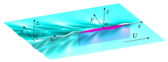
Figure 1.
Coordinate systems.
In , based on the assumptions of ideal fluid and irrotational flow, the total velocity potential should satisfy the following equations:
Laplace’s equation in fluid domain:
The kinematic and dynamic boundary conditions on the free surface :
where is the free surface elevation, is the gravitational acceleration. The subscripts (i.e., t, x0, y0) denote the derivatives with respect to the corresponding variables.
By combining Equation (2) and Equation (3), the following boundary condition on is derived:
The boundary condition on the body surface :
where is the unit normal vector directed inward of the body surface with ; is instantaneous velocity of the body surface
Moreover, a radiation condition should be satisfied. The details for implementing the numerical radiation condition will be introduced in Section 3.
By using the Galilean transformation, the relation from to can be transformed as:
where is the time derivative in coordinate system and is the time derivative in the moving coordinate system .
In , assuming that the velocity potential can be written as:
where is the steady velocity potential; , and are the spatial parts of the incident, diffraction and radiation velocity potentials, respectively; is the incoming wave amplitude, is the amplitude of -th mode of oscillating motion, and is the encounter frequency.
2.1. Nonlinear Steady Wave-Making (NSWM) Problem
Substituting Equation (7) into Equations (1)–(5), using and Equation (6), and extracting the terms unrelated to time t, the BVP of the steady wave-making velocity potential can be expressed in the moving coordinate system as:
Laplace’s equation in fluid domain:
The boundary condition on the free surface :
The boundary condition on the body surface :
By using Equation (6), the steady hydrodynamic pressure can be obtained from Bernoulli’s equation:
The steady force can then be calculated by integrating the pressure over the wetted body surface:
By using Equation (6), the steady free surface elevation can be obtained from Equation (3):
The boundary condition Equation (9) is nonlinear. To solve the resulting nonlinear BVP, the velocity potential and the free surface elevation are expressed by perturbation expansion until second order as:
Substituting Equation (14) into Equations (8)–(10), the BVPs for the first- and second-order steady velocity potentials can be obtained by Taylor expansion on and about the mean wetted body surface . The BVP for the first-order steady velocity potential is given as:
The BVP for the second-order steady velocity potential is given as:
2.2. Diffraction Problem
For the diffraction problem, the ship moves with a constant speed in waves without oscillations. In deep water, the incident wave velocity potential is given as:
where is the incident wave frequency, is the wave number, is the wave angle and represents head sea condition. The encounter frequency is defined as:
Substituting Equation (7) into Equations (1)–(5), using and Equation (6), and extracting the terms related to time t and , the BVP of the diffraction potential can be derived as:
Laplace’s equation in fluid domain:
The free surface boundary condition on :
where RHS
The boundary condition on the mean wetted body surface :
It is worth noting that in Equation (24), the nonlinear steady potential is also considered in the free surface boundary condition.
Once the diffraction potential is obtained, the wave exciting forces on the hull can be computed as:
2.3. Radiation Problem
For the radiation problem, it is assumed that the ship undergoes a harmonic oscillation. Similar to the BVP of diffraction potential, the radiation potential should satisfy the control equation and boundary conditions below:
Laplace’s equation in fluid domain:
The free surface boundary condition on :
The boundary condition on the mean wetted body surface :
where the terms representing the coupling effect between the steady and unsteady flows are given as:
where
It is worth noting that the effect of the nonlinear steady potential occurs not only in the so-called terms in Equation (30), but also in the free surface boundary condition Equation (29).
Once the radiation potential is determined, the added mass and damping coefficient can be obtained as:
3. Desingularized Rankine Panel Method
In this paper, a desingularized Rankine panel method is applied, where the Rankine sources are distributed inside the body and above the free surface at a distance according to the formula proposed by Cao et al. [17], and are equal to 1.0 and 0.5 respectively and is the local mesh size (the square root of the local mesh area), as demonstrated in Figure 2.
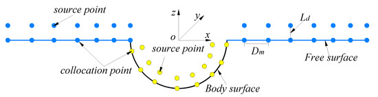
Figure 2.
Desingularized Rankine panel model.
A suitable radiation condition should be implemented to ensure a unique solution for the specific BVP when using the Rankine source method. Typically, the numerical techniques can be classified as follows:
- The upstream radiation condition [21]: imposing a boundary condition by difference method at the upstream boundary of the truncated free surface to ensure that no scattered waves propagate ahead of the vessel.
- The staggered method [22]: shifting the source points above the free surface a certain distance downstream.
- The fluid domain decomposition method [23]: the flow field is divided into an inner domain and an outer domain by vertical control surfaces, where the Rankine source is adopted in the inner area, while the Kelvin source is adopted in the outer domain, and the solutions are matched on the control surfaces.
- The modified Sommerfeld radiation condition [24,25]: the modified Sommerfeld radiation condition is adopted by taking account the Doppler shift of the scattered waves at the control surface that truncates the infinite fluid domain.
In this study, the radiation condition is satisfied by using the staggered method for its simple implementation and good stability. The raised source points are moved a distance toward downstream. The recommended parameter in this study is , where denotes the average longitudinal value between two adjacent collocation points on the free surface. However, it should be noted that this numerical treatment is only valid for steady wave-making problem and the radiation problem with the Brard number .
By using NURBS, the points on the body and free surfaces can be described with parameter coordinate as:
where are the control points on the body and free surfaces; is the weight; and are the B-spline basis functions of k(l)-th order for a given knot sequence , defined as:
According to Green’s theorem, the velocity potential in the flow field can be expressed as:
where is the field point, is the source point on the integration surface , represents the distance between the field point and the source point; is the source strength distribution over the surface and represent the coordinates of collocation point and source point, respectively.
Applying the corresponding boundary conditions on the free surface and body surface , the integral equations for the unknown source strengths can be established and solved. The velocity potential on and the normal derivative of the velocity potential on are calculated by:
where and denote the collocation points on the free surface and the body surface ; and denote the source points on the integration surface. is the integration surface above the free surface , and is the integration surface inside the body surface . is the given velocity potential at and is the given normal derivative of the velocity potential at .
Discretizing the body surface and the free surface into and quadrilateral panels respectively, a set of discrete equations can be obtained from the integral equations. From Equations (36) and (37) it follows:
As can be seen from the discrete equations of Equations (38) and (39), the total number of equations is equal to the number of unknowns, i.e., . Therefore, by satisfying the corresponding boundary conditions on the body surface and free surface at the collocation points, a set of linear equations for the unknown source strengths can be obtained. By solving these equations, the source strengths can be determined.
4. Numerical Results and Discussion
Two cases are studied: a sphere given by Equation (40), and a Wigley I ship [26] given by Equation (41):
where is the radius of the sphere and is the submerged depth; L, B and T are the length, the beam and the draft of the hull respectively. The Wigley I ship has the length to beam ratio and the beam to draft ratio .
Figure 3 shows the typical panel arrangements of the submerged sphere and the Wigley I ship. In addition, the panel arrangements on the raised plane (cyan) above the free surface are shown. In Figure 3a, the free surface of the computational domain extends to 5.0r upstream, 5.0r sideways and 10.0r downstream. The discretized panels of the sphere and the half width free surface are 21 × 21 and 50 × 16, respectively. In Figure 3b, the free surface of the computational domain extends to 1.0L upstream, 0.75L sideways and 1.5L downstream. The discretized panels of the half Wigley I ship and half width free surface are 30 × 10 and 76 × 19, respectively.
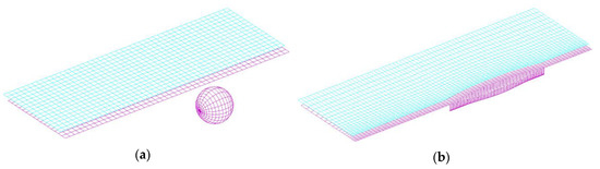
Figure 3.
Typical panel arrangements of (a) submerged sphere and (b) Wigley I ship.
4.1. Results of the NSWM Problem
In order to compute the NSWM flow, a submerged moving sphere of at three different submerged depths is chosen as the study case, the Froude number is defined as , so the results at the same Froude number will correspond to different forward speeds when the submerged depth is varied. The numerical results are compared with the analytical results of Wu and Taylor [27]. Figure 4 shows the dimensionless nonlinear wave-making resistance coefficient and lift force coefficient of the sphere, where the “linear” results are obtained by solving the BVP of the first-order steady velocity potential, the “nonlinear” results are obtained from the BVPs of the superposition of the first-order and second-order steady velocity potentials; and .
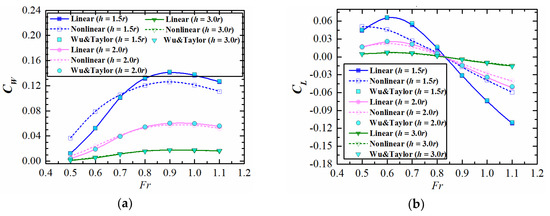
Figure 4.
Coefficients of wave-making resistance (a) and lift force (b) at different Fr.
As can be seen from Figure 4, the present results are in good agreement with the analytical results in Wu and Taylor [27] for the linear solution. As can be seen in Figure 4a, the nonlinear results are larger than the linear results when the Froude number is less than a certain threshold value, whereas the situation reverses when it exceeds the threshold. However, a converse trend can be seen for the lift force in Figure 4b. A similar result can also be found in Kim [28]. This may be attributed to the “bow and stern wave-making effect”, i.e., when a nonlinear free surface boundary condition is considered, the pressures at the bow and the stern will be different from those when a linear free surface boundary condition is considered. In addition, the differences between the linear and nonlinear results decrease when the submerged depth increases, which demonstrates that the effect of the nonlinear boundary condition on the free surface can be ignored when the submerged depth exceeds a certain value, which is also the case in reality.
4.2. mj-Terms
The difficulty in solving a radiation problem lies in the accurate calculation of mj terms, which contain the second-order derivatives of the steady velocity potential in the body boundary condition [29]. In order to calculate the mj-terms to verify the calculation accuracy of the derivatives of the velocity potential on the body surface, the desingularized method is applied to a sphere () moving at a speed in unbounded fluid.
The results of the first-order and second-order derivatives of the velocity potential are shown in Figure 5a–c, and the results of are shown in Figure 5d. It shows that the numerical results virtually coincide with the analytical solutions, which demonstrates that the present method is suitable for calculating the first- and second-order derivatives of the velocity potential on the body surface.
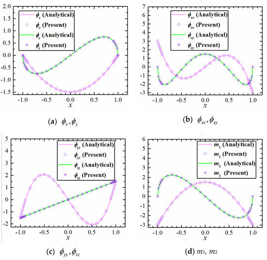
Figure 5.
Derivatives of the velocity potential and mj terms on the sphere surface along equator line.
4.3. Results of the Diffraction Problem
Table 1 and Table 2 present the non-dimensional real and imaginary parts of the surge and heave wave exciting forces on the submerged sphere (h = 2.0r) moving at in head waves as function of the non-dimensional wave number obtained by the present method in comparison with the analytical results in [27], where . As can be seen in Table 1 and Table 2, in general the present results based on the NSWM flow are in better agreement with those in [27] than the results based on the NK flow. Some deviations are observed at low frequencies, especially for the results based on the NK flow. There are two explanations for this larger deviation at low frequencies: firstly, NK flow cannot deal accurately with the relatively high forward speed because the wave disturbance induced by the forward speed of the body is neglected. Secondly, there exists a critical frequency at the Brard number , which is associated with the radiation condition [10]. Since the critical frequency is for this case, poor accuracy is resulted when the frequency is near the critical frequency.

Table 1.
Surge wave exciting forces on the sphere (Fr = 0.4, h = 2.0r, kcr = 0.26808).
Table 2.
Heave wave exciting forces on the sphere (Fr = 0.4, h = 2.0r, kcr = 0.26808).
Figure 6 shows the non−dimensional amplitudes and corresponding phase angles of heave and pitch wave exciting force/moment for the Wigley I ship advancing at in head waves, where is the displacement volume. In order to investigate the influence of different steady flow models on wave exciting forces at various wave frequencies, the results based on the NK, DB and NSWM flows are compared in Figure 6. From Figure 6 one can observe that the present results obtained based on the three different steady flow models are in favourable agreement with the results obtained by Kara and Vassalos [30] using a 3D time domain method based on a transient free surface Green function, as well as with the experimental results by Journée [26]. In addition, one can also find that the results based on the NSWM flow and other two methods based on the NK and DB flows do not show evident differences, the reasons can be explained as follows: on one hand, though the effect of nonlinear steady flow is considered in the free surface boundary condition Equation (24), the interaction has no relation with the diffraction potential in the body surface boundary condition Equation (25); on the other hand, the small differences can be attributed to the predominant proportion of the Froude–Krylov force in the wave exciting force. Therefore, it can be concluded that the effect of the NSWM potential contributes unremarkably to the wave exciting force.
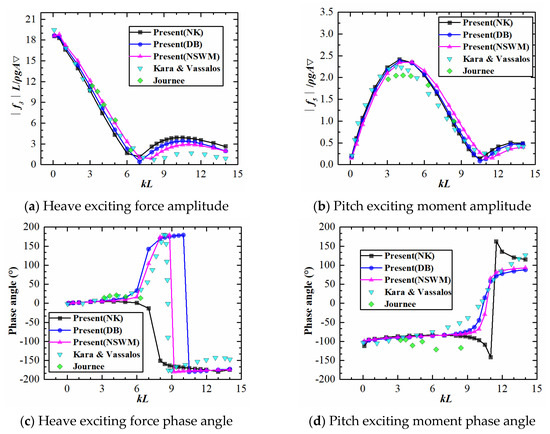
Figure 6.
Amplitudes and phase angles of heave and pitch exciting force/moment on Wigley I ship (Fr = 0.4).
Figure 7 shows the real part of the diffraction wave contour for the submerged sphere (, ) and the Wigley I ship (, ) based on the NSWM flow.
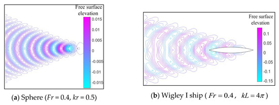
Figure 7.
Real part of diffraction wave contour of (a) submerged sphere and (b) Wigley I ship.
4.4. Results of the Radiation Problem
Table 3, Table 4 and Table 5 present the added masses and damping coefficients of the submerged sphere (h = 2.0r) moving at in surge, sway and heave motions respectively, where the added masses and damping coefficients are non-dimensionalized as , . The kecr corresponds to the critical frequency at the Brard number . As it can be seen from these tables, the numerical results based on the NSWM flow agree well with the analytical results in [27] and the numerical results in [10]. It should be noted that the linear steady wave-making potential was used to evaluate terms in [10], without considering in the free surface boundary condition. From these results, it can be concluded that the effects of the free surface nonlinearities are very weak due to the submerged depth.
Table 3.
Added masses and damping coefficients of the sphere in surge motion (Fr = 0.4, h = 2.0r, kecr = 0.3906).
Table 4.
Added masses and damping coefficients of the sphere in sway motion (Fr = 0.4, h = 2.0r, kecr = 0.3906).
Table 5.
Added masses and damping coefficients of the sphere in heave motion (Fr = 0.4, h = 2.0r, kecr = 0.3906).
Table 6 presents the coupling added masses and coefficients. It can be seen that the present results almost show the reverse relations, i.e., , which is consistent with the results in [27].
Table 6.
Coupling added masses and damping coefficients of the sphere (Fr = 0.4, h = 2.0r, kecr = 0.3906).
Figure 8 shows the heave and pitch hydrodynamic coefficients of the Wigley I ship at , where the coupling hydrodynamic coefficients are non-dimensionalized as , . As it can be seen in Figure 8, good agreement is achieved among the present numerical results and the results in [30] using NK flow and a transient free surface Green function method, and the experimental results by Journée [26]. The results based on the NSWM flow show in general better agreement with the experimental results than those obtained using DB and NK flows, especially in the low frequency ranges. However, a remarkable deviation can be observed for the heave damping coefficient in Figure 8b. This is because the uniform flow is taken as the basic flow in the method using NK flow, correspondingly the second-order derivatives of the steady potential are neglected in the terms. As a result, this treatment cannot accurately reflect the interaction between the steady flow and the unsteady flow in the body surface boundary condition. On the other hand, as explained in [9], the larger contribution of the steady velocity potential in both the body surface and free surface boundary conditions at low frequencies also leads to relatively larger deviations, but these effects are not fully considered in the method using DB flow. Therefore, the coupling effects between the nonlinear steady flow and the unsteady flow, which are reflected in both the free surface boundary condition and the terms in the body surface boundary condition, are quite important for the prediction of hydrodynamic coefficients, especially at low frequencies.
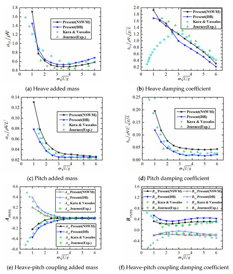
Figure 8.
Added masses and damping coefficients of Wigley I ship (Fr = 0.4).
Figure 9 shows the real part of the heave radiation wave contour of the sphere (, ) and the Wigley I ship () based on the NSWM flow.
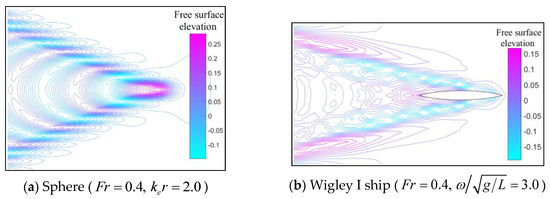
Figure 9.
Real part of the heave radiation wave contour of (a) submerged sphere and (b) Wigley I ship.
5. Conclusions
In this paper, a desingularized Rankine panel method based on the NSWM flow is applied for analysis of the hydrodynamic problems of a ship advancing in waves. NURBS are used to describe the body surface and the free surface. The wave exciting forces and the hydrodynamic coefficients are computed by solving the diffraction problem and radiation problem, respectively. A numerical study is carried out for a submerged sphere and a modified Wigley hull advancing in head waves. The numerical results are compared with the analytical solutions as well as other numerical results and experimental results available in literature. The following conclusions can be drawn.
(1) The numerical results of the wave exciting forces, added masses and damping coefficients computed using the present numerical method show good agreement with the published numerical and experimental results, which verifies the reliability of the present method. A comparison among the results indicates that the method based on the NSWM flow can generally give better agreement with the experimental and other published results than those based on NK and DB flows, especially for the hydrodynamic coefficients in relatively low frequency ranges.
(2) The NSWM potential has an influence on the prediction of the wave exciting forces. However, differences among different steady flow models are not very remarkable due to the dominant proportion of the Froude–Krylov force for the considered cases. The coupling effects between the nonlinear steady flow and the linear unsteady flow are important for the prediction of hydrodynamic coefficients, particularly at low frequencies.
(3) Compared with the time domain method, considering the NSWM flow as basic flow can be used as a more practical and faster numerical tool for evaluating the hydrodynamic performances of a ship in the early design stage.
In the present study, the method based on the NSWM flow is only applied for a submerged sphere and a modified Wigley hull. For reliable verification and application of this numerical method, further study on various ship forms needs to be carried out. Besides, in the numerical study, the squat of the hull (i.e., the trim and sinkage) is neglected. For the cases at larger forward speed, the numerical accuracy could be further improved by taking the effects of trim and sinkage into account. In addition, the desingularized Rankine panel method is only applied for the cases of Brard number larger than 0.25, where the radiation condition is satisfied by the staggered method. For , more robust methods for satisfying the radiation condition, such as the modified Sommerfeld radiation condition in [24,25], should be adopted. These will be the focuses of the future studies.
Author Contributions
Methodology, T.M.; formal analysis, T.M. and Z.Z.; Investigation, T.M.; writing—original draft preparation, T.M.; writing—review and editing, M.C., E.L. and Z.Z. All authors have read and agreed to the published version of the manuscript.
Funding
This research was funded by China Scholarships Council, grant number 201806230196; Lloyd’s Register Foundation.
Acknowledgments
The first author gratefully acknowledges the financial support from China Scholarship Council (CSC), and from the Lloyd’s Register Foundation (LRF) through the joint centre involving University College London, Shanghai Jiao Tong University, and Harbin Engineering University. LRF helps protect life and property by supporting engineering-related education, public engagement, and the application of research.
Conflicts of Interest
The authors declare no conflict of interest.
References
- Ogilvie, T.F.; Tuck, E.O. A Rational Strip Theory of Ship Motion, Part I; Report No. 013; University of Michigan: Ann Arbor, MI, USA, 1969. [Google Scholar]
- Salvesen, N.; Tuck, E.O.; Faltinsen, O.M. Ship motions and sea loads. Trans. Soc. Nav. Archit. Mar. Eng. 1970, 78, 250–287. [Google Scholar]
- Kim, K.H.; Kim, Y.H. Comparative study on ship hydrodynamics based on Neumann-Kelvin and double-body linearizations in time-domain analysis. Int. J. Offshore Polar Eng. 2010, 20, 265–274. [Google Scholar]
- Zhang, X.S.; Bandyk, P.; Beck, R.F. Seakeeping computations using double-body basis flows. Appl. Ocean Res. 2010, 32, 471–482. [Google Scholar] [CrossRef]
- Zhang, X.S.; Beck, R.F. Fully nonlinear computations of wave radiation forces and hydrodynamic coefficients for a ship with a forward speed. In Proceedings of the 30th International Workshop on Water Waves and Floating Bodies, Bristol, UK, 12–15 April 2015. [Google Scholar]
- Zhang, W.; Zou, Z.J. Time domain simulations of radiation and diffraction by a Rankine panel method. J. Hydrodyn. 2015, 27, 635–646. [Google Scholar] [CrossRef]
- Seo, M.G.; Kim, Y.H. Numerical analysis on ship manoeuvring coupled with ship motion in waves. Ocean Eng. 2011, 38, 1934–1945. [Google Scholar] [CrossRef]
- Zhang, W.; Zou, Z.J.; Deng, D.H. A study on prediction of ship manoeuvring in regular waves. Ocean Eng. 2017, 137, 367–381. [Google Scholar] [CrossRef]
- Chen, X.; Zhu, R.C.; Zhao, J.; Zhou, W.J.; Fan, J. Study on weakly nonlinear motions of ship advancing in waves and influences of steady ship wave. Ocean Eng. 2018, 150, 243–257. [Google Scholar] [CrossRef]
- Gao, Z.L.; Zou, Z.J. A NURBS-based high-order panel method for three-dimensional radiation and diffraction problems with forward speed. Ocean Eng. 2008, 35, 1271–1282. [Google Scholar] [CrossRef]
- Bunnik, T.H.J. Seakeeping Calculations for Ships, Taking into Account the Non-linear Steady Waves. Ph.D. Thesis, Delft University of Technology, Delft, The Netherlands, 1999. [Google Scholar]
- Söding, H.; Shigunov, V.; Schellin, T.E.; el Moctar, O. A Rankine panel method for added resistance of ships in waves. J. Offshore Mech. Arct. Eng. 2014, 136, 031601-1–031601-7. [Google Scholar] [CrossRef]
- Chillcce, G.; el Moctar, O. A numerical method for manoeuvring simulation in regular waves. Ocean Eng. 2018, 170, 434–444. [Google Scholar] [CrossRef]
- Riesner, M.; von Graefe, A.; Shigunov, V.; el Moctar, O. Prediction of non-linear ship responses in waves considering forward speed effects. Ship Technol. Res. 2016, 63, 135–145. [Google Scholar] [CrossRef]
- Riesner, M.; el Moctar, O. A time domain boundary element method for wave added resistance of ships taking into account viscous effects. Ocean Eng. 2018, 162, 290–303. [Google Scholar] [CrossRef]
- Cao, Y.; Schultz, W.; Beck, R. Three-dimensional desingularized boundary integral methods for potential problems. Int. J. Numer. Methods Fluids 1991, 12, 785–803. [Google Scholar] [CrossRef]
- Beck, R.; Cao, Y.; Lee, T. Fully nonlinear water wave computations using the desingularized method. In Proceedings of the 6th International Conference on Numerical Ship Hydrodynamics, Iowa City, IA, USA, 2–5 August 1993. [Google Scholar]
- Feng, A.C. A continuous desingularized source distribution method describing wave-body interactions of a large amplitude oscillatory body. J. Offshore Mech. Arct. Eng. 2015, 137, 021302-1–021302-10. [Google Scholar] [CrossRef]
- Feng, A.C.; Bai, W.; You, Y.X.; Chen, Z.M.; Price, W.G. A Rankine source method solution of a finite depth, wave-body interaction problem. J. Fluids Struct. 2016, 62, 14–32. [Google Scholar] [CrossRef]
- Feng, A.C.; Bai, W. Numerical simulation of wave radiation and diffraction problems with current effect. In Proceedings of the 12th International Offshore and Polar Engineering Conference, International Society of Offshore and Polar Engineers, Gold Coast, Australia, 4–7 October 2016. [Google Scholar]
- Nakos, D.E.; Sclavounos, P.D. On steady and unsteady ship wave patterns. J. Fluid Mech. 1990, 215, 263–288. [Google Scholar] [CrossRef]
- Jensen, G.; Mi, Z.X.; Söding, H. Rankine source methods for numerical solutions of steady wave resistance problem. In Proceedings of the 16th Symposium on Naval Hydrodynamics, Berkeley, CA, USA, 13–16 July 1986; pp. 575–582. [Google Scholar]
- Aanesland, V. A hybrid model for calculating wave-making resistance. In Proceedings of the 5th International Conference on Numerical Ship Hydrodynamics, Hiroshima, Japan, 24–28 September 1989. [Google Scholar]
- Das, S. Hydroelasticity of Marine Vessels Advancing in a Seaway. Ph.D. Thesis, University of Hawaii, Honolulu, HI, USA, 2011. [Google Scholar]
- Das, S.; Cheung, K.F. Hydroelasticity of marine vessels advancing in a seaway. J. Fluids Struct. 2012, 34, 271–290. [Google Scholar] [CrossRef]
- Journée, J.M.J. Experiment and Calculations on Four Wigley Hullforms; Report No. 909; Delft University of Technology, Ship Hydrodynamics Laboratory: Delft, The Netherlands, 1992. [Google Scholar]
- Wu, G.X.; Taylor, R.E. Radiation and diffraction by a submerged sphere at forward speed. Proc. R. Soc. Lond. A Math. Phys. Sci. 1988, 417, 433–461. [Google Scholar]
- Kim, W.D. Nonlinear free-Surface effects on a submerged sphere. J. Hydronautics 1969, 3, 29–37. [Google Scholar] [CrossRef]
- Chen, X.B.; Malenica, S. Interaction effects of local steady flow on wave diffraction-radiation at low forward speed. Int. J. Offshore Polar Eng. 1998, 8, 102–109. [Google Scholar]
- Kara, F.; Vassalos, D. Time domain prediction of steady and unsteady marine hydrodynamics problem. Int. Shipbuild. Prog. 2003, 50, 317–332. [Google Scholar]


© 2020 by the authors. Licensee MDPI, Basel, Switzerland. This article is an open access article distributed under the terms and conditions of the Creative Commons Attribution (CC BY) license (http://creativecommons.org/licenses/by/4.0/).