Article

Influence of Tidal Current, Wind, and Wave in Hebei Spirit Oil Spill Modeling

1
Department of Civil Engineering, Catholic Kwandong University, Gangneung-si, Gangwon-do 25601, Korea
2
Department of Civil and Environmental Engineering, Nagoya University, Furo-cho, Chikusa-ku, Nagoya 464-8603, Japan
*
Author to whom correspondence should be addressed.
J. Mar. Sci. Eng. 2020, 8(2), 69; https://doi.org/10.3390/jmse8020069
Submission received: 9 January 2020 / Accepted: 21 January 2020 / Published: 22 January 2020
(This article belongs to the Special Issue Numerical Models in Coastal Hazards and Coastal Environment)

Abstract

:
The purpose of this study is to investigate the effects of three external forces (tidal current, wind, and waves) on the movement of oil spilled during the Hebei Spirit oil spill accident. The diffusion of the spilled oil was simulated by using a random walk (RW) model that tracks the movement caused by advection-diffusion assuming oil as particles. For oil simulation, the wind drift current generated by wind and tidal current fields were computed by using the environmental fluid dynamics code (EFDC) model. Next, the wave fields were simulated by using the simulating waves nearshore (SWAN) model, and the Stokes drift current fields were calculated by applying the equation proposed by Stokes. The computed tidal currents, wind drift currents, and Stokes drift currents were applied as input data to the RW model. Then, oil diffusion distribution for each external force component was investigated and compared with that obtained from satellite images. When the wind drift currents and Stokes drift currents caused by waves were considered, the diffusion distribution of the spilled oil showed good agreement with that obtained from the observation.

1. Introduction

In South Korea, international trade and oil imports are increasing rapidly because of industrial development and rapid economic growth. In terms of the transportation involved in import and export, marine transport allows for transcontinental transportation with low freight rates by enabling simultaneous transport of large amounts of cargo. Therefore, in South Korea, more than 90% of the trading volume relies on marine transport; further, oil traffic accounts for about 30% of all marine transportation. Oil supertankers with capacities of 100,000 tons arrive and depart at ports more than 800 times annually, which increases the possibility of the occurrence of oil spill accidents. Such oil spills are caused by marine accidents involving ships (stranding, collision, and sinking), or due to carelessness; more than 300 cases occur annually.
The Hebei Spirit oil spill accident in the Yellow Sea was the largest marine oil spill in South Korea (Figure 1). This oil spill occurred at about 7:30 Korea standard time (KST) on 7 December 2007 (22:30 universal time coordinated (UTC) on 6 December 2007), approximately 10 km northwest off (126°03.1′ N, 36°52.3′ E) from Manripo beach, Taean of South Chungcheong Province, Korea [1]. A crane barge (Samsung 1), which was being towed by tugs (Samsung T5 and Samho T3) collided with an anchored very large crude oil carrier (VLCC, Hebei Spirit) carrying 263,541 tons of crude oil, registered to Hong Kong, thereby damaging the VLCC cargo tanks. The collision punctured three of the five tanks and resulted in the leakage of about 10,900 tons of cargo oil (Iranian heavy crude, Kuwait export crude, and UAE Upper Zakum crude). Although the oil recovery ship with a capacity of 200–500 tons arrived shortly after the accident, it was impossible to handle the spill because of the high waves (2–4 m) and strong winds (14–16 m/s); further, the installed oil fence proved ineffective due to the high waves. According to the Korea Coast Guard (KCG) report [2], the spilled oil after the accident spread out rapidly toward coastlines because of the northwestern winds and currents during the next 30 days, thereby contaminating more than 375 km of coastlines on the west coast of South Korea. In particular, approximately 70 km of the Taean Peninsula shoreline was heavily impacted by thick stranded oil.The Ministry of Oceans and Fisheries (MOF) of South Korea predicted that the spilled oil after the incident would reach the beach within 24 h; however, it reached the beach within 13 h. The spilled oil affected the marine ecosystem because of harsh weather and the failure of initial disaster prevention. Thus, an oil spill is declared as a type of disaster because it not only causes the destruction of marine ecosystems but also incurs large costs in terms of damage compensation and cleaning up spilled oil. If the range of the spilled oil and the location and time to reach the beach are predicted accurately after the occurrence of the spill with a forecasting system that considers spilled oil diffusion, the damage can be reduced considerably.
The diffusion of spilled oil is a very complicated natural phenomenon that combines factors such as tidal flow (tidal currents, ocean currents, wind drift currents, longshore currents, and so on), weather (wind, water temperature, evaporation, and so on), waves, and biochemical reactions. Tidal currents, wind, and waves are especially important in predicting the range of oil diffusion, and if they are considered properly, the range of oil diffusion can be predicted accurately [3].
Several studies have been conducted to reproduce the oil spill movement and evaluate the environmental and ecological impacts of the Hebei Spirit accident. Kim et al. [4] investigated the effect of tides on the travel time of oil spills through subtidal flow and examined the differences between subtidal flow simulation with and without tides, using a regional oceanic modeling system (ROMS) [5]. The authors concluded that tides should be included to accurately predict oil spill trajectories in a tide-dominated area such as the Yellow Sea. Kim et al. [6] investigated the effect of the wind drift factor for the Hebei Spirit accident under strong tidal conditions by comparing numerical simulation results with satellite image data. Lee et al. [7] simulated the wind waves to account for the oil transport caused by waves including the Stokes drift caused by weakly nonlinear waves. Yim et al. [8] monitored stranded oil for its identity and weathering status in three contaminated provinces along the west coast of South Korea. Kim et al. [9] applied a neural network (NN) and an adaptive threshold method to detect the oil slicks resulting from the Hebei Spirit accident and to monitor their evolution from synthetic aperture radar (SAR) images. They reported variations in the extent of the oil spill and its movement as affected by currents and winds. Kim et al. [10] evaluated the spatiotemporal variations and the rate of oil contamination in the water column following the Hebei Spirit oil spill to account for the oil contamination in the seawater of the intertidal zone exposed to continuous oil contamination from the oiled shoreline. Kim et al. [11] discussed the major shortcomings of Korea’s oil spill compensation process and provided policy implications for promoting social and economic recovery in affected communities and maximizing residents’ satisfaction through the compensation process. Meanwhile, Samaras et al. [12] introduced the oil-holding-capacity approach to estimate oil concentration on the coast and the permanent oil attachment to the coast, and they tested for the Lebanon oil spill of 2006, using an open source Lagrangian oil spill model, the so-called MEDSLIK-II, developed by De Dominicis et al. [13]. However, there are few studies that evaluate the diffusion of oil considering the effect of external forces such as tides, wind, and waves simultaneously.
This paper presents the numerical results of the Hebei Spirit oil spill accident, considering three external forces (tidal current, wind, and waves). Tidal currents and wind drift currents were calculated by using the environmental fluid dynamics code (EFDC) model; the simulating waves nearshore (SWAN) model was applied to calculate the Stokes drift currents caused by waves. The oil spill diffusion was simulated by the random walk (RW) model based on the calculated three factors. The calculated oil diffusion distribution was compared with the observation data obtained 13 h after the oil spill, at which the spilled oil flowed into the shore of Manripo and Sinduri beach (8 p.m., on 7 December 2007), and at the time when the satellite image was taken (11 a.m., on 11 December and 2007) by the European space agency (ESA). Moreover, the effects of tidal currents, wind, and waves on oil diffusion distribution were investigated.
The remainder of this paper is organized as follows. Section 2 describes the adopted numerical approach and input data of the Hebei Spirit oil spill simulation and the field observation data. In Section 3, numerical results are discussed, focusing on the effects of the consideration of tidal currents, wind drift currents, and Stokes drift currents on oil spill diffusion. Finally, Section 4 presents conclusions.

2. Materials and Methods

2.1. Numerical Model

The oil spill model was constructed by following the steps illustrated in Figure 2. To investigate the effect of tidal current, wind, and waves on oil spill, the Hebei Spirit oil spill was employed as the numerical model. We constructed an oil spill diffusion model that can be considered for tidal current, wind drifts current caused by wind, and Stokes drift current caused by waves. Then, we reviewed the oil diffusion distribution based on each factor.
The EFDC and SWAN model were used for the calculations of tidal and wind drift currents and waves, respectively. The Stokes drift currents were also calculated by using wave heights, wave periods, and wave directions from the SWAN model results. These tidal and wind drift currents and the Stokes drift currents are applied to the RW model as input data, and the oil transport in the RW model are modeled by tracking particles that represent individual portions of the spill [14]. The models applied in the current study are briefly described below, focusing on the governing equations.
The EFDC model has been applied to rivers, lakes, reservoirs, wetlands, estuaries, and coastal ocean regions and was originally developed at the Virginia Institute of Marine Science (VIMS) in support of the environmental assessment and management of the US. It was developed and changed by many workgroups, wherein the hydrodynamic part of the model was built by Hamrick [15] and published on US EPA Public Domain. The EFDC model has been tested and validated by many researchers in a wide range of hydrodynamic and environmental studies [16,17,18,19,20,21]. The EFDC model solves the three-dimensional, vertically hydrostatic, free surface, turbulent averaged equations of motions for a variable density fluid. Dynamically coupled transport equations for turbulent kinetic energy, turbulent length scale, salinity, and temperature are also solved. The model uses a stretched or sigma vertical coordinate and Cartesian or curvilinear, orthogonal horizontal coordinates to represent the physical characteristic of a water body. In this study, we used the EFDC-DS version, which was modified, and we added preprocessing and post-processing functions in Fortran 95 code, developed by Craig [22]. The governing equations for the EFDC hydrodynamic model are given below.
The continuity equation is as follows:
( m ζ ) t + ( m y H u ) x + ( m x H v ) y + ( m w ) z = 0 ,
The momentum equation is as follows:
( m H u ) t + ( m y H u u ) x + ( m x H v u ) y + ( m w u ) z ( m f + v m y x u m x y ) H v = m y H ( g ζ + p ) x m y ( h x z H x ) p z + z ( m 1 H A v u z ) + Q u ,
( m H v ) t + ( m y H u v ) x + ( m x H v v ) y + ( m w v ) z ( m f + v m y x u m x y ) H u = m x H ( g ζ + p ) y m x ( h y z H y ) p z + z ( m 1 H A v v z ) + Q v ,
where t is time, ζ is the free-water level, H is the total depth ( H = h + ζ ), and h is the mean water depth; u ,   v ,   and   w are the velocities in the directions of x ,   y , and z coordinates; m = m x m y ,   m x ,   and   m y are the transformation scale factors in the horizontal coordinates; f is the Coriolis parameter; Q u and Q v are the source and sink term, respectively; and p is pressure, g is the gravitational acceleration, and A v is the vertical turbulent determined by the Mellor–Yamada Level 2.5 turbulence closure model [23]. Further details and technical descriptions of the EFDC model are provided in the report by Hamrick [15].
The SWAN model—specifically designed for coastal applications—was developed at the University of Delft in the Netherlands; it is one of the wave models widely used by engineers and scientists for wave research [24,25,26,27]. The SWAN model considers the generation of wind-induced waves, the wave refraction caused by changes in water depth, white capping, and bottom friction, and the disappearance of waves caused by wave breaking, reflection, and diffraction by structures. The model is a third-generation wave model for obtaining realistic estimates of wave parameters in coastal areas, lakes, and estuaries from the given wind, bottom, and current conditions. Further details on the first-, second-, and third-generation wave models can be found in [24]. The SWAN model is based on the spectral action balance equation to account for wave–current interaction. The formulation of the action balance equation in Cartesian coordinates is given as follows:
N t + c g , x N x + c g , y N y + c σ N σ + c θ N θ = S σ ,
where N ( σ , θ )   is the action density spectrum, σ   is the relative radian frequency, θ   is the propagation direction normal to the wave crest of each spectral component, and t is time; c g , x , c g , y , c σ , and c θ   denote the propagation velocity in the x -space, y -space, σ -space, and θ -space, respectively; and S   is the source term in terms of energy density, including atmospheric input, dissipation owing to depth-induced wave breaking, bottom friction, and white-capping, triad, and quadruplet nonlinear wave-wave interactions. The first term on the left-hand side of Equation (4) represents the local rate of change of action density in time, and the second and third term represent the propagation of action in the x and y space. The fourth and fifth term represent the relative frequency shift and refraction caused by variations in depth and currents. The right-hand side of this equation represents the effects of wave generation, dissipation, and nonlinear wave–wave interactions. The details of the model and technical descriptions are explained in the report by Booij et al. [24].
In the RW model, oil is assumed to be a collection of particles floating above the water surface. This model applies the Lagrangian method to trace the location of particles, which move independently with time, owing to the advection and diffusion with constant volume. The advection term is calculated by using flow velocities, and the diffusion term is calculated by using the random walk theory. This method has better numerical stability and saves computation time compared to the conventional Eulerian method. When the particles are passive contaminants, the moving positions of the particles owing to advection and diffusion are obtained by the drift velocity vector ( U and V ) and the dispersion velocity component ( u and v ) as follows:
{ X ( t + Δ t ) =   X ( t ) + U Δ t +   u Δ t Y ( t + Δ t ) =   Y ( t ) + V Δ t +   v Δ t ,
where the drift velocity and dispersion velocity components are defined as follows:
{ U = u + D x x x + D x y y + D x x h h x + D x y h h y V = v + D x y x + D y y y + D x y h h x + D y y h h y ,
{ u =   u L cos θ u T sin θ v =   u L sin θ + u T cos θ u L = R 1 2 D L Δ t u T = R 2 2 D T Δ t θ = tan 1 ( v / u ) ,
where   h is the water depth; u and v are velocity components in x - and y - directions, respectively; D L and D T are horizontal diffusion coefficients in the   x - and y - directions, respectively; and R 1 and R 2 are random numbers.

2.2. Field Observation

Satellite images and wind and wave conditions were investigated to specify the sea and weather conditions nearby Taean on the day of the Hebei Spirit oil spill; the conditions were then adopted as the calibration and input data for the simulation.

2.2.1. Satellite Image

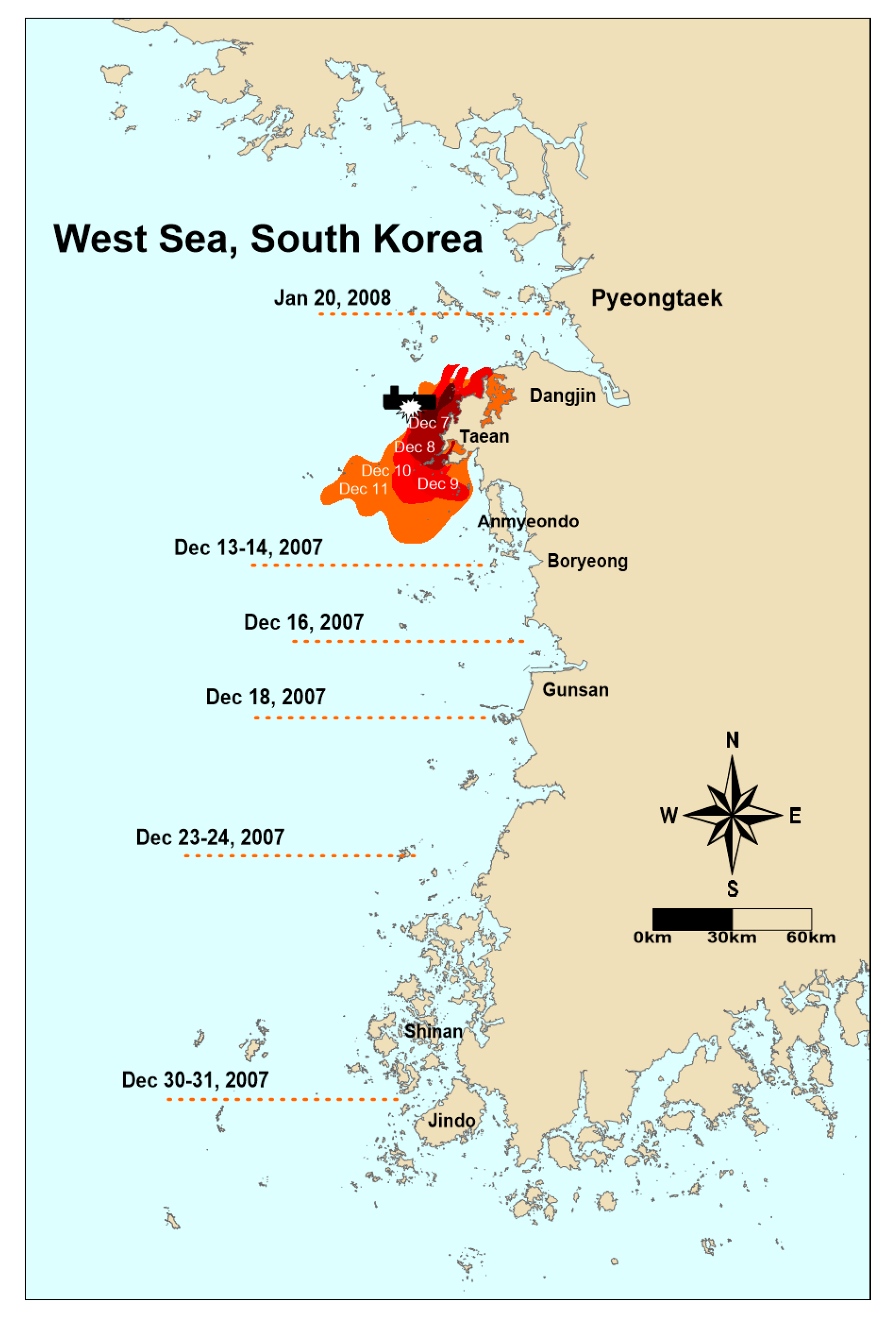
Figure 3 shows the satellite image taken by ESA at 11 a.m., on 11 December 2007. As shown in Figure 3, most of the oil flowed to Taean at 11 a.m., on 11 December 2007, 5 days after the oil spill occurred at 7 a.m., on 7 December 2007; the southern part of spilled oil spread out to the sea near Anmyeondo. According to the study by Kim et al. [11], the oil spread rapidly and in the largest amounts to the outermost coastlines of the Taean peninsula and then gradually southward, as far as the Shinan coast, as shown in Figure 4. Further, they reported that, tar—crude oil turns into tar—was found in the waters near Gunsan in 10 days (100 km away) and in the Shinan waters in South Jeolla Province in about 21 days (250 km away). Because of less quantitative field data, Figure 3 and Figure 4 depicting the trend of oil spill distribution were employed for comparison with numerical results.

2.2.2. Wind Observation

Figure 5 shows the time series data of wind direction and speed observed every hour from 1 December until 31 December 2007, on the Gadaeam buoy belonging to the Korea Meteorological Administration. The wind speed on 7 December 2007—the day of the accident—was a maximum of 16.8 m/s, and the wind direction was from the northwest. After that, the wind speed gradually decreased, and the wind direction turned eastward before and after 10 December. The wind-observation data were used as input data for the EFDC model to simulate the tidal current, considering wind drift currents.

2.2.3. Wave Observation

Figure 6 shows the time series data of significant wave height and period observed every hour from 1 December until 31 December 2007, on the Gadaeam buoy belonging to the Korea Meteorological Administration. The significant wave height showed a maximum of 3.0 m on 7 December 2007. After that, harsh weather continued from 3 a.m. until 3 p.m. with the wave height over 2.0 m. The significant wave period was 3.0–5.0 s t, and it showed 3.0–4.0 s except for 3.0–6.0 s 25 days after the accident. The observed wave data were used as input data for the SWAN model.

3. Results

3.1. Verification of the Tidal Model

Figure 7 shows the location of the verification points and the bathymetric chart for the numerical simulation. The numerical domain was set at 130 km east–west, 113 km south–north direction from Anmyeondo to Youngheungdo. The grid size is 500 m, and a valid grid number of a total of 39,241 each composed of 264 each east–west and 230 each south–north was designed. Further, a three-dimensional model with three vertical layers, which considers that the oil movement mostly occurred on the surface layer, was constructed. The ratio of the vertical layer was set to 0.01 (surface layer), 0.09 (middle layer), and 0.90 (bottom layer). The thickness of each layer in the EFDC model was set by multiplying the vertical layer ratio and water depth. In the RW model, the velocity of the surface layer was applied.
The numerical simulation was performed for 16 days from 7 December 2007, when the Hebei Spirit oil spill occurred, until 22 December 2007; the duration of the simulation includes the day when the satellite image was captured (11 December 2007). The tide was based on four major tidal components, which are M2 (lunar semidiurnal), S2 (solar semidiurnal), K1 (lunisolar declinational, diurnal), and O1 (lunar diurnal).
To examine the reliability of the numerical model in this study, the model was verified based on the observed data obtained by the Korea Hydrographic and Oceanographic Agency of the tidal elevation at three points (T-1–3), which were measured by RBR’s XR-420-TG (pressure logger), and tidal currents at the two points (C-1–2), which were measured by AANDERAA’s RCM7 (doppler current meter), as shown in Figure 7a. Tidal currents were measured at 5 m under the water surface. The vertical layers of the numerical model were set at ratios of 0.01, 0.09, and 0.90, as described above, and thus, the computed tidal currents used for the numerical verification at the same water depth as the observed data were calculated by interpolating the tidal currents at each layer.
The time series of the calculated tidal elevation and currents for 16 days, from 7 December 2007 until 22 December 2007, were compared with those of the observed data. Figure 8 and Figure 9 show the numerical results of the time series of the tidal elevation at Taean (T-1), Sinjindo (T-2), and Backsajang (T-3), and the tidal currents at the points of C-1 and C-2. The solid and circle sign indicate the observed and computed data, respectively. Although there is a small difference, good agreements in both the tidal elevation and tidal current velocity can be seen between the observed and computed data. Therefore, it implies that the tide amplitude, tide phase, and tidal currents are reproduced properly in the numerical model. The observed and calculated harmonic constants of tidal elevation and currents and errors are presented in Table 1, Table 2 and Table 3.

3.2. Tide and Wind Numerical Experiment

As shown in Figure 2, the numerical experiments were performed for Case 1, considering only tidal currents, and Case 2, considering tidal currents and wind drift currents simultaneously. In Case 2, additional wind time-series data were input during the numerical experiment.
Figure 10, Figure 11, Figure 12 and Figure 13 show the simulation results for Case 1 of flood and ebb tidal currents on the surface and bottom layers during the spring tide. Figure 10 and Figure 11, which represent the tidal currents of the flood, are snapshots of 10 December 2007, captured at 2 p.m. Figure 12 and Figure 13, showing tidal currents of the ebb, are snapshots captured at 9 p.m., on 10 December 2007. The figures show that the currents flow northeastward at flood tide and flow southwestward at the ebb. The surface flow velocity is approximately 1–2 m/s at the flood and ebb tides in the Taean. The magnitude of the flow velocity in the surface layer (vertical layer ratio 0.01) was greater than in the bottom layer (vertical layer ratio 0.90).
Figure 14 shows a snapshot of the tidal currents at 9 a.m., on 1 December 2007, when the wind speeds were the highest after the oil accident. Considering both the tidal and wind drift currents, Case 2 illustrates a good flow to Sinduri Beach.

3.3. Wave Numerical Experiment

As shown in Case 3, in Figure 2, a wave numerical experiment was performed to consider the Stokes mean drift caused by the external force in the oil spill numerical experiment. The Korea Coast Guard (KCG) report [2] suggested that the oil arrived at Sinduri Beach 13 h after the oil spill. As shown in Figure 6, the weather during this period was severe, with a wave height of 1.0–3.0 m. To observe the effect of Stokes mean drift in this scenario, the wave heights and periods observed in the Gadaeam buoy were averaged from 7 a.m. to 8 p.m., on 7 December 2007. The averaged observation data at Gadaeam buoy are a wave height of 2.0 m and a period of 3.5 s. Next, the simulation of wave deformation caused by the SWAN model was repeated through trial and error, until the numerical results were consistent with the average observation data (H = 2.0 m, T = 3.5 s) at the Gadaeam buoy. The calculated wavefield data were then applied to the Stokes mean drift. The Stokes mean drift was calculated from the following equation proposed by Stokes [28]:
U S t o k e s = π 2 H 2 L 2 c c o s h ( 2 k h ) s i n h 2 ( k h ) ,
where H is the wave height, L is the wavelength, c is the wave speed, k is the wave number, and h is the water depth.
Stokes mean drift was applied as an external force to oil spill simulation from 7 a.m. to 8 p.m., on 7 December 2007. Figure 15 shows the numerical results satisfying the wave conditions observed at the Gadaeam buoy simulated by the SWAN model. From the co-wave height map in Figure 14, it is confirmed that the wave height is 1.5–2.0 m near Taean.

3.4. Oil Spill Numerical Experiment

The oil spill model considers the factors of tidal currents, wind drift currents, and Stokes drift currents for the Hebei Spirit oil spill. The distribution of oil spill diffusion was investigated, considering the effects of each factor. The simulation duration was five days from 7 December 2007, when the oil spill occurred, to 11 December 2007. The duration includes the event wherein the spilled oil flowed into Manipo and Sinduri beach at 8 p.m., on 7 December 2007. The diffusion range of the spilled oil was simulated and verified by comparing the observed data and the simulation data. The spilled oil particles were released 20 each per 60 s for 9 h at the location of the oil spill with the assumption that the discharge of the spilled oil continued for 9 h.
To maintain the simplicity of the RADOM-WALK model and focus on the effects of the tidal currents, wind, and waves on oil diffusion distribution, the spilled oil particles did not consider coastal soil types and evaporation, and they were designed to be conservative and modeled to be trapped onshore. Further, the movements on the advection and diffusion of the horizontal plane at the surface were targeted; movements in the vertical plane were not considered. The horizontal diffusion coefficient was applied at 15 m2/s.

3.4.1. Oil Spill Distribution Considering Tidal Currents (Case 1)

The results of the oil spill diffusion simulation considering only tidal currents are shown in Figure 16. As shown in the results of the diffusion distribution of the spilled oil 13 h after the accident (8 p.m., on 7 December 2007, when the spilled oil reached Manripo and Sinduri beach), the spilled oil spread out in the northeast and southwest direction by the typical reversing tidal currents because of the northeastward currents at the flood and the southwestward currents at the ebb. However, oil attachment to the shore is not observed because there is no shoreward flow as shown in Figure 14a. According to the oil diffusion distribution five days after the accident (11 a.m., on 11 December 2007), the oil moved to northeast–southwest direction, owing to the advection and diffusion caused by the reversing tidal currents. The oil diffusion distribution seemed almost similar to that seen in the satellite image, whereas the diffusion distance between the south and north directions was shorter than that in the observed data in the satellite image; further, a small amount of oil reached the beach.

3.4.2. Oil Spill Distribution Considering Tidal and Wind Drift Currents (Case 2)

Figure 17 shows the result of the oil spill diffusion simulation considering tidal currents and wind drift currents. The result at 8 p.m., on 7 December 2007, shows a similar diffusion trend to the case considering only tidal currents, such as spreading out to the northeast–southwest direction because of the typical reversing tidal currents. However, in this case, it is observed that some spilled oil approaches the Manripo and Sinduri beach, owing to the wind drift current. According to the results at 11 a.m., on 11 December 2007, the spilled oil continued to diffuse in the northeast–southwest direction because of the reversing tidal currents, and the spilled oil reached the beach owing to the wind drift current. Moreover, the diffusion distance between the south and north seemed to almost match with the diffusion distribution of the satellite image. Thus, based on these results, it was determined that the wind drift currents contributed to oil attachment to the coast.

3.4.3. Oil Spill Distribution Considering Tidal, Wind Drift, and Stokes Drift Currents (Case 3)

Figure 18 shows the result of oil spill diffusion simulation considering the tidal, wind drift, and Stokes drift currents. According to the oil spill diffusion distribution at 8 p.m., on 7 December 2007, the spilled oil diffused in the northeast–southwest direction was similar to that in the other cases. In addition, more spilled oil reached Manripo and Sinduri beach than that in Case 2 because of the Stokes drift currents caused by waves. This tendency is well-matched with the opinion of the locals that the oil reached the Manripo and Sinduri beach in the early stage, about 13 h after the accident. The results at 11 a.m., on 11 December 2007, show the analogous diffusion characteristics to the case considering wind drift currents. The diffusion distance between the south and north directions almost matched with the diffusion distribution seen in the satellite image.

4. Conclusions

In this study, an oil spill diffusion model was established, considering tidal currents, wind, and waves by reproducing the Hebei Spirit oil spill, a major oil spill in South Korea. The three-dimensional model was established based on the fact that spilled oil moves on the water surface by setting up three layers vertically. Surface flow velocity was used in the spilled oil distribution simulation for the Hebei Spirit oil spill. When the wind drift currents and Stokes drift currents caused by waves were considered, the diffusion distribution of the spilled oil showed good agreement with that obtained from the observation. For reproducing the Hebei Spirit oil spill model, the tidal current was an important factor to identify oil movement in the northeast–southwest direction, and the wind drift current and the Stokes drift current caused by waves were important for identifying the spilled oil movement for reaching the beach. These results suggest that the prediction of wind and waves is the most important factor to forecast oil spill diffusion that can reach the beach shore in the early stage; in addition, it is necessary to consider the wind and Stokes drift currents to simulate the oil diffusion phenomenon.

Author Contributions

Conceptualization, K.-H.L.; methodology, T.-G.K.; data curation, T.-G.K. and Y.-H.C.; writing-original draft preparation, K.-H.L. and T.-G.K.; writing-review and editing, K.-H.L., T.-G.K. and Y.-H.C.; supervision, K.-H.L. All authors have read and agreed to the published version of the manuscript.

Funding

This research received no external funding.

Conflicts of Interest

The authors declare no conflict of interest.

References

  1. Report of Investigation into the Collision between the Hong Kong Registered Ship “Hebei Spirit” and Korean Crane Barge “Samsung No.1” on 7 December 2007. Hong Kong Special Administrative Department, Marine Department, Marine Accident Investigation Section. Available online: https://www.mardep.gov.hk/en/publication/pdf/mai071207a_f.pdf (accessed on 27 December 2019).
  2. Korea Coast Guard (KCG). Korea Coast Guard 2008 White Paper; Korea Coast Guard: Seoul, Korea, 2008. [Google Scholar]
  3. Seo, S.W. Hydraulic Characteristics and Prediction Technology of Taean Oil Spill Diffusion. Korean Soc. Coast. Ocean Eng. 2008, 1, 53–64. (In Korean) [Google Scholar]
  4. Kim, C.S.; Cho, Y.K.; Choi, B.J.; Jung, K.T.; You, S.H. Improving a prediction system for oil spills in the Yellow Sea: Effect of tides on subtidal flow. Mar. Pollut. Bull. 2013, 68, 85–92. [Google Scholar] [CrossRef] [PubMed]
  5. Shchepetkin, A.F.; McWilliams, J.C. The regional oceanic modeling system (ROMS): A split-explicit, free-surface, topography-following-coordinate oceanic model. Ocean Model. 2005, 9, 347–404. [Google Scholar] [CrossRef]
  6. Kim, T.H.; Yang, C.S.; Oh, J.H.; Ouchi, K. Analysis of the Contribution of Wind Drift Factor to Oil Slick Movement under Strong Tidal Condition: Hebei Spirit Oil Spill Case. PLoS ONE 2014, 9, e87393. [Google Scholar] [CrossRef]
  7. Lee, J.L.; Lee, D.Y.; Kim, I.C. Numerical Modeling of Wave Effect on Hebei Spirit Oil Spill (2007), Taean, Korea. J. Coast. Res. 2009, 56, 836–840. [Google Scholar]
  8. Yim, U.H.; Ha, S.Y.; An, J.G.; Won, J.H.; Han, G.M.; Hong, S.H.; Kim, M.K.; Jung, J.H.; Shim, W.J. Fingerprint and weathering characteristics of stranded oils after the Hebei Spirit oil spill. J. Hazard. Mater. 2011, 197, 60–69. [Google Scholar] [CrossRef]
  9. Kim, T.S.; Park, K.A.; Li, X.; Lee, M.J.; Hong, S.W.; Lyu, S.J.; Nam, S.Y. Detection of the Hebei Spirit oil spill on SAR imagery and its temporal evolution in a coastal region of the Yellow Sea. Adv. Space Res. 2015, 56, 1079–1093. [Google Scholar] [CrossRef]
  10. Kim, M.K.; Han, S.H.; Won, J.H.; Yim, U.H.; Jung, J.H.; Ha, S.Y.; An, J.G.; Joo, C.K.; Kim, E.S.; Han, G.M.; et al. Petroleum hydrocarbon contaminations in the intertidal seawater after the Hebei Spirit oil spill effect of tidal cycle on the TPH concentrations and the chromatographic characterization of seawater extracts. Water Res. 2013, 47, 758–768. [Google Scholar] [CrossRef]
  11. Kim, D.H.; Yang, G.G.; Min, S.J.; Koh, C.H. Social and ecological impacts of the Hebei Spirit oil spill on the west coast of Korea: Implications for compensation and recovery. Ocean Coast. Manag. 2014, 102, 533–544. [Google Scholar] [CrossRef]
  12. Samaras, A.G.; De Dominicis, M.; Archetti, R.; Lamberti, A.; Pinardi, N. Towards improving the representation of beaching in oil spill models: A case study. Mar. Pollut. Bull. 2014, 88, 91–101. [Google Scholar] [CrossRef]
  13. De Dominicis, M.; Pinardi, N.; Zodiatis, G.; Lardner, R. MEDSLIK-II, a Lagrangian marine surface oil spill model for short-term forecasting—Part 1: Theory. Geosci. Model. Dev. 2013, 6, 1851–1869. [Google Scholar] [CrossRef] [Green Version]
  14. Grisolia-Santos, D.; Spaulding, M.L. The influence of oil particle size distribution as an initial condition in oil spill random walk models. In Oil and Hydrocarbon Spills, Modeling, Analysis and Control II; Rodríguez, G., Brebbia, C., Eds.; WIT Press: Southampton, UK, 2000; Volume 44, pp. 19–28. [Google Scholar]
  15. Hamrick, J.M. A three dimensional environmental fluid dynamics computer code: Theoretical and computational aspects. In Special Report in Applied Marine Science and Ocean. Engineering; Virginia Institute of Marine Science, College of William and Mary: Williamsburg, VA, USA, 1992; No. 317; 63p. [Google Scholar]
  16. Kuo, A.Y.; Shen, J.; Hamrick, J.M. The effect of acceleration on bottom shear stress in tidal estuaries. J. Waterw. Port Coast. Ocean Eng. 1996, 122, 75–83. [Google Scholar] [CrossRef]
  17. Shen, J.; Boon, J.D.; Kuo, A.Y. A modeling study of a tidal intrusion front and its impact on larval dispersion in the James River estuary, Virginia. Estuaries 1999, 22, 681–692. [Google Scholar] [CrossRef]
  18. Moustafa, M.Z.; Hamrick, J.M. Calibration of the wetland hydrodynamic model to the Everglades nutrient removal project. Water Qual. Ecosyst. Model. 2000, 1, 141–167. [Google Scholar] [CrossRef]
  19. Ji, Z.G.; Hamrick, J.H.; Pagenkopf, J. Sediment and metals modeling in shallow river. J. Environ. Eng. 2002, 128, 105–119. [Google Scholar] [CrossRef]
  20. Wool, T.A.; Davie, S.R.; Rodriguez, H.N. Development of three-dimensional hydrodynamic and water quality models to support TMDL decision process for the Neuse River estuary, North Carolina. J. Water Resour. Plan. Manag. 2003, 129, 295–306. [Google Scholar] [CrossRef]
  21. Zou, R.; Carter, S.; Shoemaker, L.; Parker, A.; Henry, T. Integrated hydrodynamic and water quality modeling system to support nutrient total maximum daily load development for Wissahickon Creek, Pennsylvania. J. Environ. Eng. 2006, 132, 555–566. [Google Scholar] [CrossRef]
  22. Craig, P.M. User’s Manual for EFDC Explorer: A Pre/Post Processor for the Environmental Fluid Dynamics Code; Dynamic Solutions, LLC: Knoxville, TN, USA, 2010. [Google Scholar]
  23. Mellor, G.L.; Yamamda, T. Development of a turbulence closure model for geophysical fluid problems. Rev. Geophys. Space Phys. 1982, 20, 851–875. [Google Scholar] [CrossRef] [Green Version]
  24. Booij, N.; Ris, R.C.; Holthuijsen, L.H. A third-generation wave model for coastal regions, Part I: Model description and validation. J. Geophys. Res. 1999, 104, 7649–7666. [Google Scholar] [CrossRef] [Green Version]
  25. Ris, R.C.; Holthuijsen, L.H.; Booij, N. A third-generation wave model for coastal regions, Part II: Verification. J. Geophys. Res. 1999, 104, 7667–7681. [Google Scholar] [CrossRef]
  26. Rusu, E.; Conley, D.C.; Coelho, E.F. A hybrid framework for predicting waves and longshore currents. J. Mar. Syst. 2008, 69, 59–73. [Google Scholar] [CrossRef]
  27. Oh, S.H.; Suh, K.D.; Son, S.Y.; Lee, D.Y. Performance comparison of spectral wave models based on different governing equations including wave breaking. KSCE J. Civ. Eng. 2009, 13, 75–84. [Google Scholar] [CrossRef] [Green Version]
  28. Stokes, G.G. On the theory of oscillatory waves. Math. Phys. Pap. 1880, 1, 197–229. [Google Scholar]
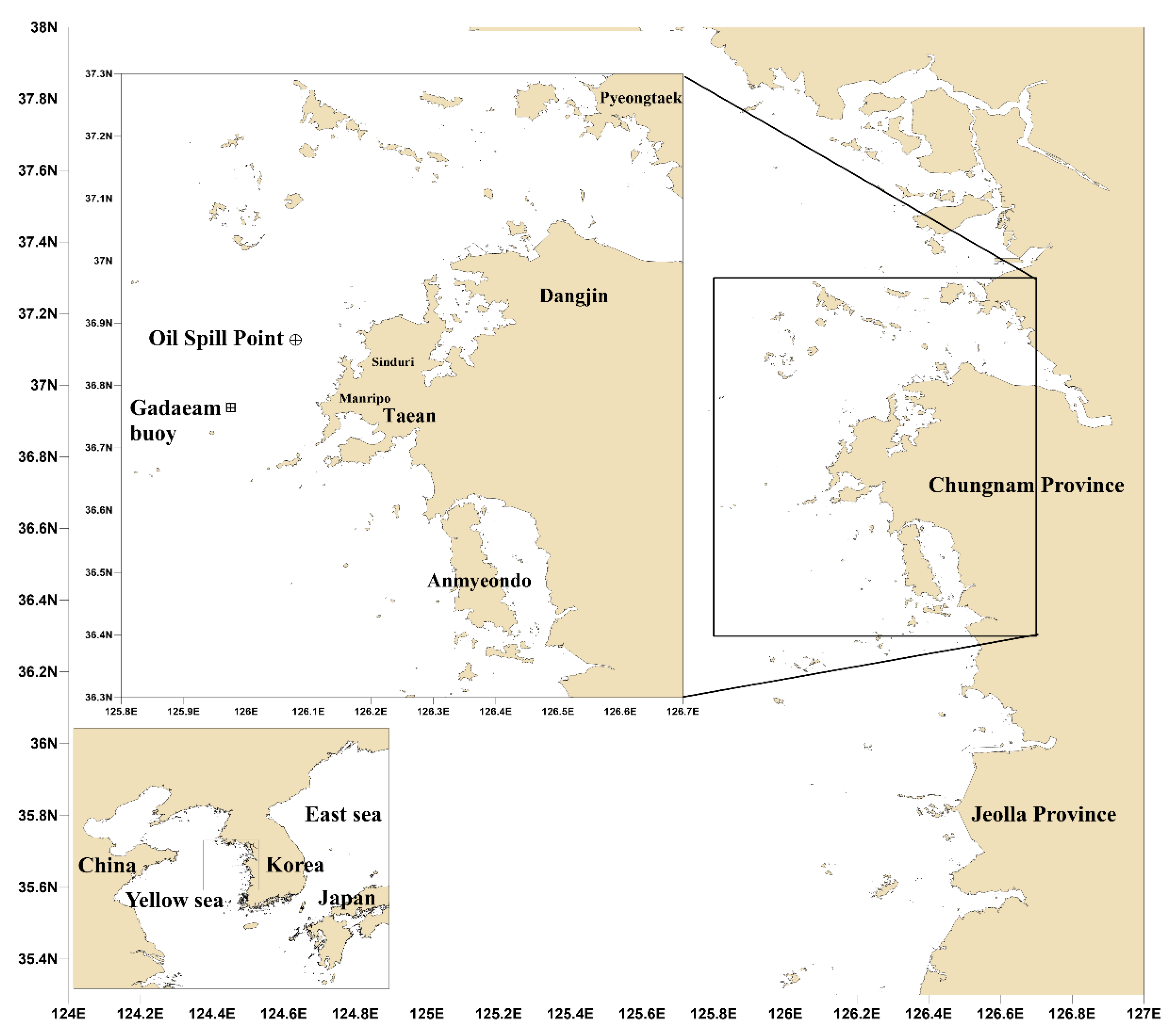
Figure 1. Map of study area. The circle and square symbols indicate the collision point of the Hebei Spirit (126°03.1′ N, 36°52.3′ E) and the location of the Gadaeam buoy (125°58.36′ N, 36°46.12′ E).
Jmse 08 00069 g001
Figure 2. Flowchart of the oil spill model.
Jmse 08 00069 g002
Figure 3. Satellite image on 11 December 2007, ESA.
Jmse 08 00069 g003
Figure 4. Spread of oil from Hebei Spirit in the west sea of Korea (reproduced from Kim et al. [11]).
Jmse 08 00069 g004
Figure 5. Time series of wind speed and direction observed in Gadaeam buoy.
Jmse 08 00069 g005
Figure 6. Time series of significant wave height and period observed in Gadaeam buoy.
Jmse 08 00069 g006
Figure 7. (a) Location of verification points (b) and bathymetric chart for numerical simulation.
Jmse 08 00069 g007
Figure 8. Comparison between observed and computed tidal elevation time series at (a) T-1, (b) T-2, and (c) T-3. The reference time is Korea standard time (KST).
Jmse 08 00069 g008
Figure 9. Comparison between observed and computed tidal current time series at (a) C-1 and (b) C-2.
Jmse 08 00069 g009
Figure 10. Flood current at spring tide in the surface layer at (a) temporal current velocity vector and (b) contour plot.
Jmse 08 00069 g010
Figure 11. Ebb current at spring tide in the surface layer: (a) temporal current velocity vector and (b) contour plot.
Jmse 08 00069 g011
Figure 12. Flood current at spring tide in the bottom layer: (a) temporal current velocity vector and (b) contour plot.
Jmse 08 00069 g012
Figure 13. Ebb current at spring tide in the bottom layer: (a) temporal current velocity vector and (b) contour plot.
Jmse 08 00069 g013
Figure 14. Surface layer snapshot of the tidal currents at 9 a.m., on 1 December 2007: (a) current velocity vector of Case 1 and (b) current velocity vector of Case 2.
Jmse 08 00069 g014
Figure 15. (a) Wave vector and (b) co-wave height map.
Jmse 08 00069 g015
Figure 16. Oil distribution considering tidal current conditions: at 8 p.m., on 7 December 2007, (a) 13 h after the accident; (b) at 11 a.m., on 11 December 2007.
Jmse 08 00069 g016
Figure 17. Oil distribution considering tidal current and wind conditions: at 8 p.m., on 7 December 2007, (a) 13 h after the accident; (b) at 11 a.m., on 11 December 2007 (right).
Jmse 08 00069 g017
Figure 18. Oil distribution considering tidal current, wind, and wave conditions: at 8 p.m., on 7 December 2007, (a) 13 h after the accident; (b) at 11 a.m., on 11 December 2007.
Jmse 08 00069 g018
Table 1. Comparison of observed and computed tidal elevation harmonic constants for M2, S2, K1, and O1 at T-1–3.
LocationTidal ComponentsAmplitude (cm)Phase (degree)Error
ObservedComputedObservedComputedAmplitudePhase
T-1M2231.6231.8106.6115.50.28.9
S290.188.1155.1160.9−2.05.8
K134.736.2287.0288.01.51.0
O128.527.3257.0260.3−1.23.3
T-2M2211.1207.595.494.2−3.6−1.2
S281.078.7138.8137.8−2.3−1.0
K135.833.3280.1278.8−2.5−1.3
O126.824.4252.1250.6−2.4−1.5
T-3M2215.7215.590.089.3−0.2−0.7
S283.381.7133.7133.8−1.60.1
K135.234.1277.5275.7−1.1−1.8
O126.325.2249.4247.5−1.1−1.9
Table 2. Comparison of observed and computed tidal velocity harmonic constants for M2, S2, K1, and O1 at C-1.
Tidal Velocity ComponentsU-componentsV-components
Amplitude (cm/s)Phase (degree)ErrorAmplitude (cm/s)Phase (degree)Error
AmplitudePhaseAmplitudePhase
M2Observed34.566.0−4.7−13.494.553.23.5−4.8
Computed29.852.698.048.4
S2Observed16.0112.6−4.7−19.336.093.1−1.3−6.3
Computed11.393.334.786.8
K1Observed5.4239.7−2.1−37.09.8207.8−1.2−5.1
Computed3.3202.78.6202.7
O1Observed3.8192.5−1.4−25.26.4158.9−0.4−1.4
Computed2.4167.36.0157.5
Table 3. Comparison of observed and computed tidal velocity harmonic constants for M2, S2, K1, and O1 at C-2.
Tidal Velocity ComponentsU-componentsV-components
Amplitude (cm/s)Phase (degree)ErrorAmplitude (cm/s)Phase (degree)Error
AmplitudePhaseAmplitudePhase
M2Observed59.436.3−10.3−3.957.538.616.3−5.3
Computed49.132.473.833.3
S2Observed23.187.8−6.4−13.222.087.32.3−13.7
Computed16.774.624.373.6
K1Observed5.3213.1−1.6−27.55.2204.20.0−18.6
Computed3.7185.65.2185.6
O1Observed3.4178.4−0.9−25.13.0168.30.4−23.6
Computed2.5153.33.4144.7