1. Introduction
The oceans cover more than two-thirds of our planet, representing the vastest part of natural resources available to us [
1]. Yet, only a fraction of the total ocean interior has been explored so far [
2,
3]. The exploitation of the available ocean resources has been predominantly associated with fishing, tourism, and offshore oil and gas production and, although limited, activity ongoing in mining or other sectors of significant industrial and societal interest [
3,
4].
There is growing demand for technological improvement in ocean exploration and monitoring to increase our understanding of the ocean interior for a valuable number of scientific, industrial, and political reasons [
5]. Deep water exploration and new data collection in this domain are of special interest to provide new insights into a variety of geological and ecological processes [
3]. For instance, there has been relevant industrial effort spent into deep water hydrocarbons exploration [
6], offshore carbon capture and storage [
7,
8], exploitation of deep-sea mineral resources, or seafloor fibre-optic cables positioning for telecommunications purposes, as well as for seafloor observatories [
9,
10]. At the same time, political drivers push toward the implementation of new coordinated marine monitoring programmes for establishing, preserving and restoring relevant Marine Protected Areas as stated in the EU Marine Strategy Framework Directive (2008/56/EC).
To satisfy all interests in marine observation, better mapping resolution is needed to increase data accuracy for geohazard analysis (e.g., landslides, fluid escape features, mobile substrates), environmental impact assessments and monitoring (e.g., leaking hydrocarbons/CO
and repeated monitoring of benthic habitats and ecosystems to protect marine biodiversity). In such context it is indicative that the General Bathymetric Chart of Oceans (GEBCO) [
11] operating under the auspices of the International Hydrographic Organization (IHO) [
12] and the Intergovernmental Oceanographic Commission (IOC) of UNESCO [
13] has set the objective to promote international collaboration for facilitating the complete mapping of the ocean floor by 2030, under the “Seabed 2030” initiative [
11].
The primary goal of the “Seabed 2030” international initiative is the acquisition of ocean floor data into a high quality 100m-resolution digital model with vast geographic coverage, as compared to older 5km-resolution data collected in past mapping expeditions [
11]. Charting the oceans and evaluating their resources is of great importance also to global economy and societal security since it provides direct information to generate more reliable climate-change models a sustainable food production chain, understand quality and status of sea habitats or explore new offshore energy and mining resources [
14].
Many monitoring systems were investigated, developed, and tested in recent decades [
9,
15,
16,
17]. A wide state of the art was reported on platforms and instruments used for integrated underwater autonomous mapping and monitoring, at different spatial and temporal scales [
15]. Fixed platforms, for example, cabled fixed observatories, oceanographic moorings and landers have been configured as a network of spatially distributed nodes covering an extended area and capable of acquiring data for long time periods (e.g., 10 years) at very high frequency (e.g., 1Hz) [
18,
19]. Nevertheless, the nodes geometry is difficult to change and the infrastructure maintenance results expensive have small spatial coverage, although they can acquire data for long time periods (e.g., 10 years) at very high frequency (e.g., 1Hz). On the other hand mobile platforms e.g., Autonomous Underwater Vehicles (AUVs) and sea gliders [
14,
20,
21] have a higherlarger spatial resolution and coverage, but smaller temporal resolution and coverage. The time and space dimension affect both surveying applications, design and operational requirements of oceanographic instruments and platforms [
15]. For example, sea gliders are not suitable for carrying out seabed mapping or to perform inspection of offshore infrastructure, due to their typical vertical thoot-sawsinusoidal trajectories. Indeed, they are equipped with downward looking altimeter for seafloor collision avoidance purposes, but do not employ monitoring acoustic devices that need to be operated along the isobaths, keeping a constant distance from the seafloor as much as possible. These instruments are widely used on AUVs, which are able to run parallel to the ocean floor ensuring the quality of the measurements. Commonly installed sensors on board of AUVs or stand-alone fixed platforms for autonomous underwater operations of ocean mapping and monitoring are summarised in
Table 1. Examples of operative contexts where AUVs are employed are summarised in
Table 2, and discussed in [
14,
16,
17].
At present, AUV-based operations generally require the support of surface vessels and are extremely complex, high-risk, and expensive [
9,
17]. The use of sophisticated AUV vehicles, which can be either propelled purely via electric thrusters or based on gliding, is also expensive because they need support vessels for their deployment and recovery increasing mission costs [
43]. Therefore, new developments in AUV technology are needed to improve their endurance and autonomy, especially with respect to deployment and recovery methods such to meaningfully reduce the mission costs. At the same time AUV technology should achieve noteworthy improvements in the capability to explore the ocean and inspect offshore infrastructure, in comparison to currently available state-of-the-art commercial systems.
The objective of this article is to present and describe the achievements of the H2020 ENDURUNS project, grant agreement n.824348, 2018–2022, [
44], which is a novel scientific and technological approach for autonomous seabed surveying in deep ocean or in coastal areas. The proposed novel approach overcome the limits of the current state of the art combining a hybrid AUV capable of moving using either thrusters or in glider mode [
45], with an Unmanned Surface Vehicle (USV) equipped with satellite communication facilities to interact with land stations, assuring quasi real-time data transfer and mission control. A valuable characteristics of the proposed approach is the use of clean and renewable energy provided by photovoltaic solar panels for the USV, and hydrogen fuel cell system combined with a rechargeable battery pack, for both AUV and USV. Moreover, a long operative autonomy is ensured by an adaptive energy management [
46].
Since the requirement and design phases of the project have been completed, this paper describes the ENDURUNS concepts design and the main AUV/USV system functionalities resulting from the first 18 months of research activities. A discussion of the main ENDURUNS achievements and future activities is provided. Finally, conclusions close the work and summarizes the main findings presented in this paper.
2. The ENDURUNS Overall Approach
The ENDURUNS approach consists of a system integrating an AUV and a USV equipped with photovoltaic panels (USV only), fuel-cells and rechargeable battery packs. The AUV is designed to navigate using its own thrusters or in glider mode. This enables the AUV to carry out autonomous long-lasting missions in vast geographical and deep-sea areas. The glider navigation mode allows the AUV to autonomously reach the survey zones, or move between different areas, without a large energy expenditure. With the thruster-based navigation the AUV can perform transects close to the seabed, increasing data acquisition richness and accuracy [
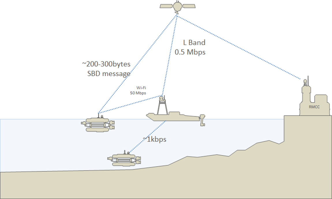
47]. The USV autonomously follows the AUV, providing information for accurate geo-localisation of the acquired data and granting satellite communication with the Remote Monitoring and Control Centre (RMCC) at a land station. Data transfer between the AUV and the USV can be obtained through acoustics communication or through wireless connection when the AUV is at sea-surface.
Figure 1 summarises the ENDURUNS approach.
Different AUV technologies are currently available for autonomous surveys operations [
14,
49] and several AUV-USV combinations were already prototyped and tested [
50,
51]. Among the most relevant AUV implementations we recall the Autosub 6000 [
14] and the Autosub Long Range [
52,
53]. The Autosub 6000 is a 5.5 m long vehicle, with a dry weight of 1800 kg, a depth rating of 6000 m and an almost 48 h autonomy. The Autosub Long Range is a relatively slow-moving propeller-driven vehicle, 4.3 m long, weighting about 800 kg with a depth rating of 6000 m and experimented in a 7 days mission in Antarctica [
53]. It is also equipped with precision-navigation and terrain-following features, as well as a sophisticated collision avoidance system. Other relevant implementations are air-deployable and launchable AUVs [
54]. Although most of these implementations focused on aerial deployment of traditional REMUS-type vehicles [
55], a NERC-funded project investigated the use of highly portable small-scale AUVs, weighting just 2.5 kg, with a range of 350 km at speeds of 0.5 ms-1 [
56].
Differently from the currently available systems, the ENDURUNS prototype is conceived for an easy deployment and for a quasi real-time interaction between the USV and the land station. Automatic AUV/USV docking capabilities allows power transfer from the USV to the AUV and data transfer in the opposite direction [
57]. The AUV is equipped with several sensors and data-acquisition devices. An additional standardized independent payload, the SeaCube, can be installed inspired by the CubeSat space technology [
58], for third party experiments. In particular, there is great interest in bathymetric and seabed survey data acquisition via multi-beams echo-sounders (MBES), as well as imaging data of the seabed [
59]. The acquired data provide a rich understanding of both the geometrical and the environmental characteristics of the seabed, for example, the morphology, the sediments type, the presence/absence and characterization of living organisms or sunken debris (e.g., wrecks, barrels, containers), reaching submetric horizontal resolution [
60,
61].
A large scale mapping survey can produce a large amount of data in short time [
10]. This amount represents an exceptional technological challenge for data processing, storage, and transfer on board of AUVs. Currently, almost all data processing tasks are handled offline by human operators after data transfer. On the contrary, the ENDURUNS approach provides fully automatic on-board data processing [
48]. Indeed, both the USV and the AUV are equipped with appropriate CPU boards allowing for the execution of simple algorithms that can interpret the acquired data, as well as simplifying and compressing it. Here, it is worthy to stress the need of simple and efficient applications to avoid large CPU requirements and to strike a good balance between antithetic needs of power consumption and mission autonomy. After data pre-processing, the information extracted from the acquired data is transmitted to the land station.
All navigation, data acquisition, and communication operations are managed by the RMCC providing the tools to plan, execute, monitor, and replay the mission.
The main innovative features characterising the ENDURUNS system are summarised in
Table 3.
3. System Functionalities
ENDURUNS vehicles can be used in different operative contexts, characterized by mission complexity and the need of a high degree of autonomy without any support vessel intervention. Within such missions the USV and the AUV can reach a specific area of interest, start surveying the area, collect, store and transmit relevant data to the RMCC. The two vehicles are capable of inter-communicating to share acquired data and information on mission status. Finally, the vehicles can autonomously return to the base or can interact with the RMCC in order to be recovered by a support vessel. The achievement of all these tasks is facilitated thanks to the following functionalities.
3.1. Hybrid Underwater Autonomous Vehicle
The ENDURUNS underwater vehicle is a torpedo shaped AUV with gliding capability. It has been designed with a modular approach, implemented as cylindrical sections, connected one to each other, leading to different AUV configurations according to the mission needs. Special effort was spent for a design with a minimal amount of protrusions, therefore the vehicle steering, in both horizontal and vertical plane, is obtained through a suitable modulation of the four rear thrusters. Moreover, in order to simplify the construction, the vehicle hull is wet and the electronic components are contained in pressure resistant cylinders. The remaining inner parts are filled with appropriate syntactic foam.
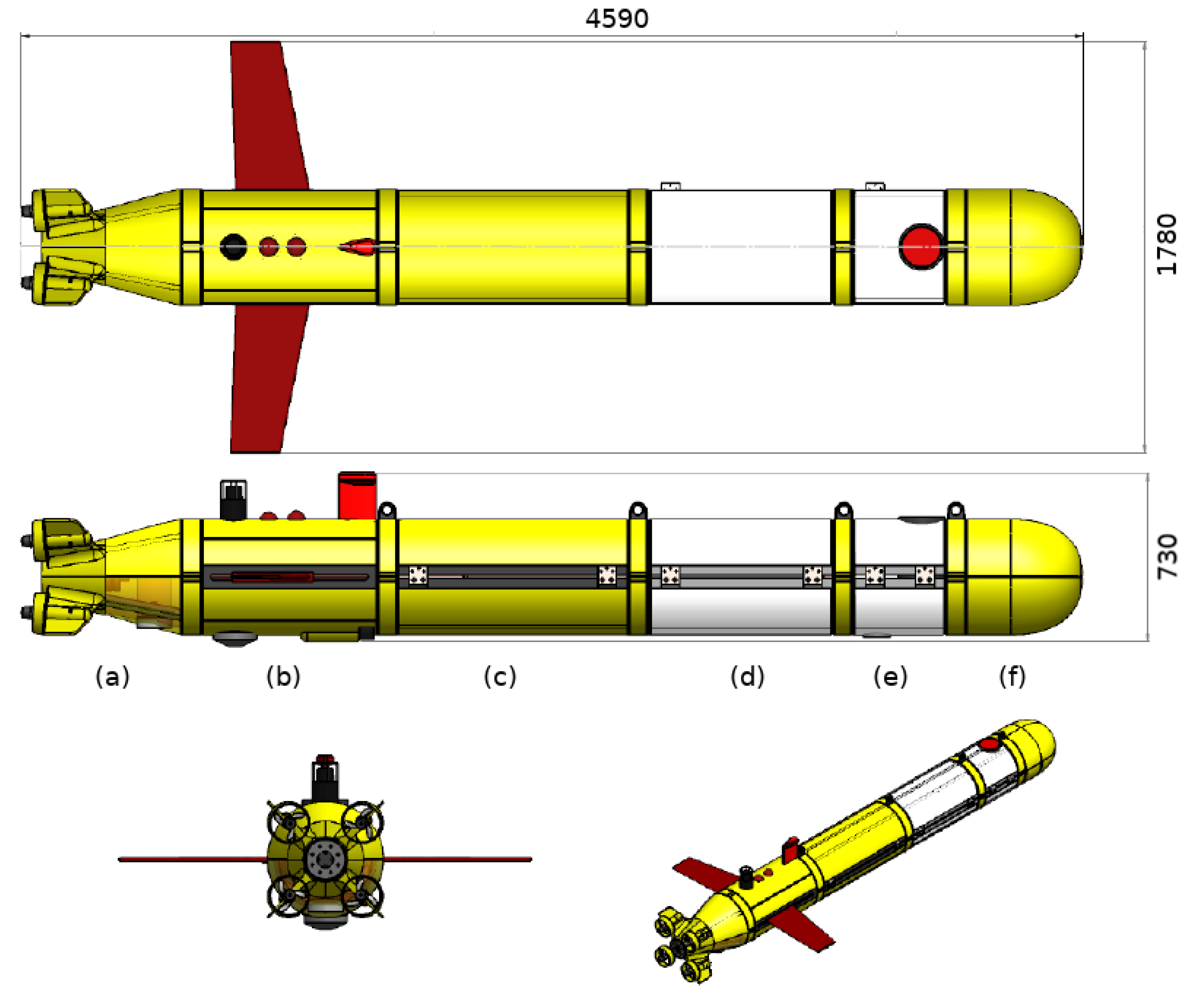
Figure 2 shows an overview of the vehicle, where the section (a) corresponds to the propulsion module containing the four thrusters and related servo boards, (b) the navigation module containing the housings with the avionics and the acoustic modem for the AUV/USV communication, (c) the primary energy module containing two battery housings acting as moving ballast in gliding mode, (d) the secondary energy module containing the fuel cell and the associated gas storage containers, (e) the payload module containing the inductive charger and the mission camera and finally the (f) nose module containing the forward looking sonar and the variable buoyancy system. The propulsion, navigation and primary energy modules must be always present, as they provide the basic functionalities of motion, sensing, processing and energy. The remaining modules can be added or removed depending on the specific application context.
The gliding capability is provided by three main components: (i) a variable buoyancy system, positioned at the vehicle bow, module (a), for maximizing the change of pitch of the vehicle associated with the variation of buoyancy; (ii) a mobile ballast in the rear section, module (c), allowing to maintain a predetermined pitch during both ascending and descending steps for maximizing the vehicle performance during gliding navigation; (iii) two wings for increasing the lift, with symmetrical profile, positioned at the centre line of the vehicle to not induce hydrodynamic effects during the navigation phases in AUV mode.
Table 4 summarises the most relevant components and sensors necessary for the navigation, installed onboard the AUV.
3.2. Unmanned Surface Vehicle
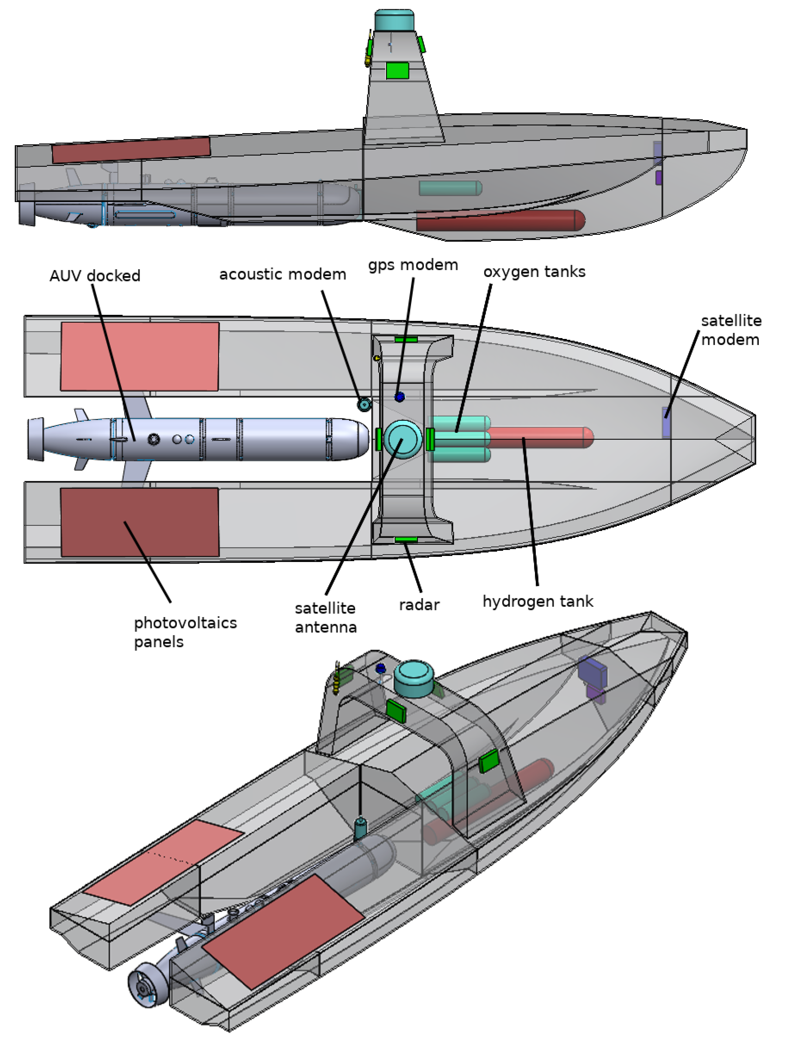
The USV is designed to act as a mothership for the AUV hybrid vehicle but also as a means of facilitating communication between the ENDURUNS remote control centre and the AUV when it is operating at depth. The USV also feeds the information to the AUV in order to confirm its exact position in the territory of the mission with the aim of providing high quality data geo-referencing.
The USV was designed to be compact and lightweight, it is 7 m long and 2 m width, manufactured using glass-fibre reinforced composites with the resin infusion method. It is a 100% electric unit, with the power pack consisting of a rechargeable Li-ion battery, flexible marinised photovoltaic panels manufactured of monocrystalline Si and a hydrogen fuel cell. The overall USV schema is represented in
Figure 3.
The Li-ion battery are used to power both the electric thrusters, which are responsible for providing mobility of the USV, and the rest of the electronic components installed on board. The photovoltaic panels are responsible for recharging the battery pack, while the fuel cell switches on only if the panels can not work properly, e.g., during the night, with bad weather conditions.
In the present configuration, the USV is not equipped with scientific instruments, but it is designed for receiving and processing onboard the scientific data acquired by the hybrid AUV. The processed information is then transferred via stellite to the RMCC. The RMCC is also connected to the autopilot of the USV, providing the necessary information to navigate to/from the target survey area. Safe navigation is guaranteed by the anti-collision system, consisting of AIS, GPS, lidar and radar systems. The
Table 5 summarizes the most relevant components installed onboard of the USV.
3.3. Power Pack and Energy Management
There are many AUV power-pack commercial systems for underwater energy storage, such as the magnesium-seawater battery system [
62], the Li-ion battery pressurized module, or aluminium-hydrogen peroxide (Al/
) semi-fuel-cell [
63], depending on the power or design requirements. The ENDURUNS project develops a novel energy-source system, based on hydrogen fuel cells [
64]. The AUV can autonomously plan its energy requirements based on its sensors-system collecting operational data. Moreover, while the project is ongoing, simulations of different operation scenarios are performed on the prototype vehicle, to assess hardware, software, and external conditions affecting battery-pack efficiency, similar to [
65], with the goal to find the configurations for an optimal consumption rate [
66].
On the other hand, the power pack for the USV is simpler than the one needed for the AUV, where in the former case, energy is obtained by two photovoltaic panels, 160 W each [
67]. Here an appropriate electrical installation is needed to manage energy production, transformation phase, and storage in the battery pack [
68].
The AUV battery pack consists of two 4 kWh Li-ion stacks, placed side by side. This array of batteries supplies the required power to the AUV internal components, for example, thrusters, onboard CPU, sensors (e.g., camera, MBES), acoustic modem, Wi-Fi antenna, buoyancy controller. The Alkaline Fuel Cell (AFC) onboard the AUV is responsible for converting the chemical energy of the stored hydrogen into electrical power for the battery pack. The AFC is placed on a separate pressure housing with respect to the required hydrogen and oxygen storage tanks. It has a maximum power output of 300 W with a maximum theoretical efficiency of 60%.
The power pack employed on the USV is similar to the one used for the AUV, with the exception that photovoltaic panels are also incorporated. The photovoltaic panels recharges two 2 kWh stacks of Li-ion batteries continuously during the daytime. The USV is also equipped with AFC, but in this case output power is 500 W instead of 300 W, as the USV weight restrictions are less severe than the AUV ones.
In the case of USV, the recharging of the Li-ion battery array is performed by the photovoltaic panels installed on its top side. If the discharging of the battery exceeds a pre-defined threshold (e.g., 20% of total charge capacity) the fuel cell switches on to recharge the battery. Once the recharging of the battery is completed, the fuel cell switches off again. In the case of the AUV a similar approach is employed, with the fuel cell switching on only when the total discharge of the Li-ion battery array drops below the pre-defined threshold (e.g., 20%). Once recharging is complete the fuel cell will switch off again until the next recharging cycle.
In the event the battery was to run out completely of charge, the AUV is designed to have inherently a positive buoyancy permitting it to resurface without the help of the electric motor.
3.4. Mission Planning
A mission can be planned by an RMCC operator executing high-level software that can formally instruct the vehicles [
48]. The operator marks one or more zones of interest on an interactive map and generates a pattern controlling both USV and AUV navigation, including specification on how to reach the survey areas and how to perform the mission. During execution, telemetry is provided as it becomes available. The AUV can navigate in gliding mode between different survey areas and then move via thrusters inside the area for acquiring the data. The
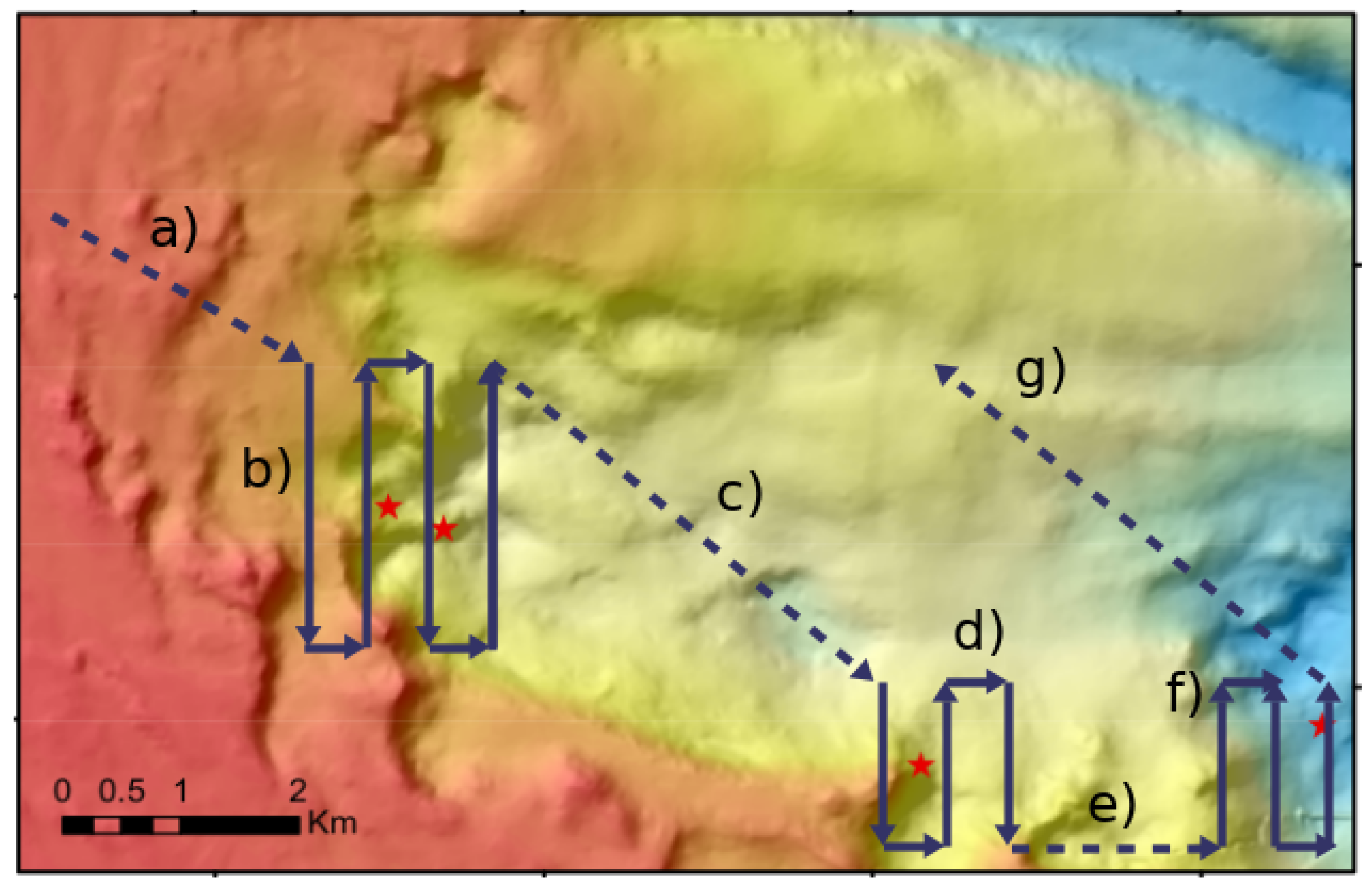
Figure 4 shows an example of complex seabed survey activity where (a) the hybrid AUV navigates in gliding mode (dashed lines) to reach the survey area (b), then it switches to thruster mode navigation for acquiring data through horizontal transects (continuous lines). After the area (b) is surveyed, the hybrid AUV moves (c) in gliding mode to the survey area d) then switches in gliding mode (e) for reaching (f). Finally, the AUV switches again in gliding mode for autonomous homing (g).
The mission planner also manages sensors, their (de)activation position and time, execution of algorithms for data analysis on board of both AUV and USV, as well as the USV-RMCC and the USV-AUV communication. After AUV-USV data transfer, a preliminary compressed map (low-resolution or classified areas) is sent to the RMCC. The user can request a higher detail image of a subsection to be transmitted by the USV. This on-demand level of detail conserves bandwidth, while still providing baseline information at all times. Using a progressive image transfer, the user does not need to wait for the transmission to be completed to get an impression of the mission environment. Based on new information, the operator can subsequently refine the mission for the AUV to perform a closer rescan of the area. The complete uncompressed map becomes available after AUV and/or USV recovery.
3.5. Data Sensing, Storage and Processing
The most relevant measuring instruments hosted by the AUV are a Multi-Beam Echo-Sounder (MBES) [
22,
61] and the imaging device for acquiring visual data of the seafloor. The MBES used onboard the AUV is a Norbit WBMS with a 400 KHz bandwidth and an average power consumption of 40 W [
69]. The imaging device is based on the technology described in the European patent [
70] and it is specifically conceived for image acquisition and processing [
71,
72]. The imaging device is conceived for having a low power consumption (i.e., 0.12 W per image) and its image acquisition module is designed to perform an optimal control of the CMOS image sensor with the aim of saving up storage space and energy. The device is equipped with a Field Program Gate Array (FPGA) integrated circuit, hosting a firmware-level image analysis algorithm capable to discard not relevant image regions.
The data acquired by AUV instrumentation will be stored onboard. Due to the power and bandwidth constraints, large amount of data cannot be easily processed and stored on board, or transferred to USV units. For this reason, the AUV is designed to host a low power consumption CPU capable to manage the hosted sensors and execute simple data compression algorithms [
48,
73,
74,
75]. The chosen board is the latest available from the Raspberry family (i.e., Raspberry Pi 4 Model B, released in June 2019) [
76]. It uses a 1.5GHz 64-bit quad-core Arm Cortex-A72 CPU with 4 GB DDR4 RAM, and an improved GPU for image/video management. Benchmarks show significant increases in speed, memory, and connectivity compared to the prior-generations, being comparable to an entry-level x86 PC systems. Power consumption is typically inside the 4–8 W range, depending on the activated units. Raspberry family has native support for all IO operations therefore the development of software interfaces is very simplified by existing packages available under Linux-based OS. This is important because AUV must be closely interfaced with the MBES, whose data transfer rate is very high (>1 MB/s, several GB/h) and so an efficient data management, cleaning and compression software tool has to be implemented onboard.
Since the USV is also designed to host an onboard computer and disposes of a larger power supply, more expensive computations will be performed on the USV. Algorithms for MBES data analysis can return a simplified bathymetric representation [
77] as well as a preliminary characterization of the terrain attributes useful for habitat-mapping tasks [
59]. Algorithms for image analysis can detect end classify relevant organisms contained in the images collected by the imaging device [
10,
72,
78,
79]. To support these algorithms, USV hosts an embedded computer (i.e., NVIDIA Jetson TX2) equipped with a GPU (massive parallel unit) [
80], ensuring high computing power with low energy consumption (about 7.5 W). More precisely, Jetson TX2 is an embedded system-on-module (SoM) with a quad-core ARM Cortex-A57, 8GB DDR4 RAM and an integrated GPU with 256 CUDA cores. It supports a wide set of highly optimized image and data processing algorithms, even those based on Deep Neural Networks (DNNs), both with native libraries or with open-source frameworks, e.g., OpenCV [
81], allowing the use of many C++/Python functions over the CUDA layer. GPU-capabilities are essential for processing onboard the full resolution sonar images provided by the MBES after AUV data transfer and before transmission, because of bandwidth constraints. Image textures are classified at the full scale and automatically tagged according to possible interesting features. Semantic classification of seabed textures and structures requires computationally intensive texture analysis algorithm based on computer vision or deep learning techniques [
78,
79,
82], but it enables the possibility of sending only relevant compressed streams to the RMCC. Onboard image processing simplifies also the task of analysing huge datasets, thus making the whole mission faster and more responsive.
3.6. SeaCube: A Third Party Payload
The SeaCube additional payload is a miniaturised and standardized structure designed to fit into the AUV hull, whereby one side is exposed to the sea water. Aim of the SeaCube is collecting and storing data independently by the other hosted sensors. This payload is inspired by the CubeSat technology, a miniaturized satellite with standard geometry and interfaces that often use off-the-shelf components. CubeSats are deployed from the International Space Station or launched to orbit as secondary payloads of a launch vehicle providing access to space for small experiments [
83,
84]. Similarly to the CubeSat, the SeaCube aims to set-up a standard system for an additional “third party” payload allowing for an economic access to the ocean interior and affordable opportunities for Student, University or SME projects and finally to increase the sensor capacities of the AUV.
Figure 5 summarize the structure of the SeaCube.
3.7. Data Communication
The AUV is designed to perform a double-link communication with the USV through acoustic modems, during underwater operations and through wireless communication at sea-surface level, close the USV, as shown in the
Figure 1.
Furthermore, the USV is capable to perform real time communication with the RMCC [
48]. As already introduced, the USV can receive mission specification and navigation instructions (e.g., changes of the mission parameters) from the RMCC. The USV can transmit quasi real-time USV- and AUV latitude/longitude coordinates, respective functioning status (e.g., battery level, sensors status, AUV real time depth, USV/AUV real time speed and direction), as well as geo-referenced data from the AUV due to the USBL system installed on both vehicles.
The AUV-USV connection via acoustic signals is bandwidth-limited in the range of kbps, with possible long connection gaps [
48]. An L-band antenna for the USV communication was chosen [
85]. These family of antennas do not have any moving parts, use electronic beam-steering to optimize gain in a certain direction, are reasonably priced, small and light. The L-band satellite link (500 kbps) connects the USV to the RMCC to relay the AUV data and receive commands, as reported graphically in
Figure 1. The USV also uses a modem to ping the RMCC command queue at certain intervals of time and determine if powering up the main antenna would be needed. This can be used to concentrate transmissions to timeframes where energy is abundantly available, or in general make information transmission more efficient.
4. Discussion
One favourable characteristics of the ENDURUNS system is the data science approach that analyses MBES data and images. Automated data processing extracts the key features from a scanned seabed-region and builds the corresponding seafloor-maps containing semantic classification outputs (e.g., accurate bathymetry data, seabed characterization, organism detection and classification) without human intervention.
ENDURUNS units can be endowed with a more general data-acquisition scope, without alteration of their main characteristics. For instance AUV/USV units promise to be an efficient and cost-effective automatic replacement for expensive and time-consuming human-led surveys, in domains like fishery, marine biology and geology, mineral exploration. This is relevant because of its combination of prolonged autonomy and flexible remote controlling, AUV/USV units are well suited to execute sound survey protocols, based on pre-planned probability-sampling schemes. The latter is an increasingly demanded requirement, for instance (and not exclusively), in fishery sciences [
86].
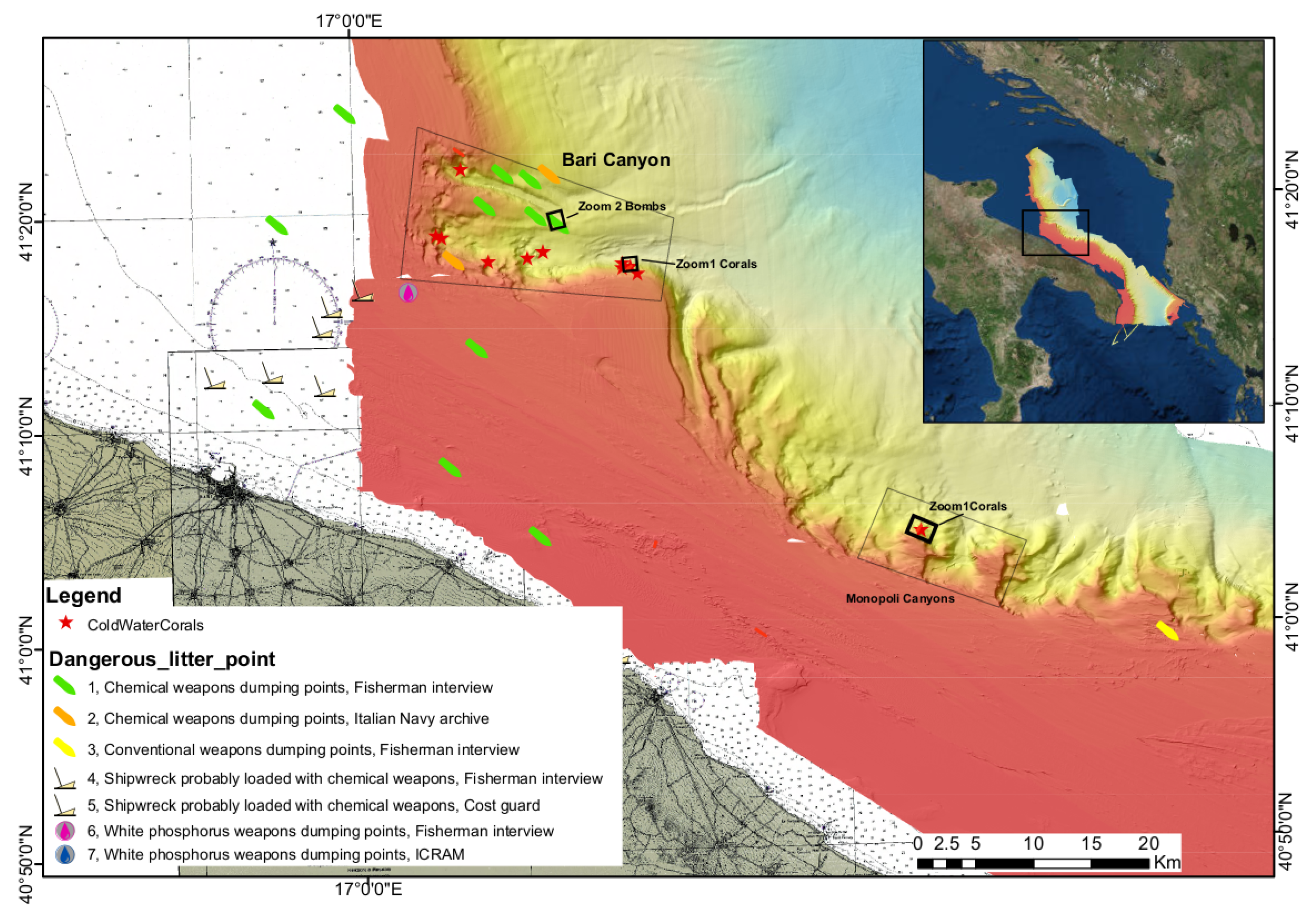
In order to demonstrate the effectiveness of ENDURUNS approach, three missions will be performed in the application contexts of the habitat mapping and infrastructure monitoring.
An habitat mapping mission will be carried out along the South Adriatic basin (Italy) characterized by a complex geomorphological and oceanographic settings and by the presence of relevant and vulnerable habitats such as the cold water corals (CWC). This area is shown in
Figure 6.
Two survey areas will be considered: the Bari canyon and the smaller incisions along the continental slope off-shore Monopoli. These areas represent two sites under annual monitoring [
87] within the EU Marine Strategy framework Directive (MSFD) survey activities, especially for the presence of CWC Habitat and the seafloor physical damages caused by human activities.
A second habitat mapping mission is planned in the Baltic sea into a site close to the city of Klaipeda (Lithuania). Within this mission a submerged forest sited into an archaeological area [
88] will be investigated. The area contains about 32 Mesolithic tree stumps and lying trunks. Within this scenario bathymetry and seafloor backscatter intensity data will be acquired. MBES data will be used for detecting relevant objects lying on the seabed like for examples, tree stumps and trunks.
The third mission will be performed in the Venice Lagoon (Italy), the largest coastal transitional ecosystem in the Mediterranean Sea and, at the same time, one of the UNESCO World Cultural and Natural Heritage sites. The lagoon is characterized by a maze of channels (maximum depth exceeding 15 m), which cut across a large area of shallow waters (average depth of 1 m), tidal flats fens and salt marshes. In this area, the MBES will be used for inspecting infrastructures of the Venice harbour and debris abandoned in the lagoon [
61].
An example of mission parameters and power consumption of the ENDURUNS AUV is shown in
Table 6 regarding the Bari Canyons area in the South Adriatic basin (see
Figure 6).
The mission described in
Table 6 consists into three MBES survey actions. In the first action a square area with the side 5 Km long is surveyed at a 200 m of distance from the seabed. The data acquisition is performed through parallel transects where 20% of each transect overlap each other. According to the MBES specifications [
69] the swath width is about 200 m, the rate of data acquisition is 60 MB per minute and the average MBES instant power consumption is about 40 W. The execution time of the survey is about 10.5 h considering an average AUV speed equals to 2 Kn. Within this context the total amount of MBES acquired data is equal to 38 GB, while the total MBES power consumption is equal 0.42 KW. Considering the thruster power consumption equals to 400 W, 4.2 KW are needed by the AUV for navigating the whole survey area, for a total power consumption equals to 4.62 KW.
The Bari Canyons area is about 22 Km from the Bari harbour, corresponding to about 2 days of AUV navigation in glider mode with an horizontal speed equal to 0.45 Km/h.
After the large area survey, the AUV should reach the sea surface and transfer the compressed acquired data to the USV. The USV should then transfer a simplified version of data to the RMCC. Moreover, if the sea state allowed for the vehicle docking, the AUV batteries should be recharged by the USV.
Table 6 shows the mission parameters for the two smaller areas Zoom 1 and Zoom 2, where the acquired data should be 8 GB and 7 GB respectively, and the power needed for performing the two survey actions is 0.97 KW and 0.88 KW respectively.
5. Conclusions
The ENDURUNS project provides a major opportunity to develop new applications in seafloor exploration and surveying, thanks to highly extended autonomy of its AUV implementation in conjunction with the USV unit.
The ENDURUNS system will contribute to the enrichment of our knowledge with respect to deep sea habitats but also geological and geophysical formations. With the capability and versatility of various types of sensor payloads combined with effective prolonged autonomy, deep ocean habitats and geophysical formations, such as ridges, volcanic sites can be mapped in high detail. Moreover, offshore infrastructures are critical for the global economy. Indeed, more and more facilities are built offshore in deeper waters and more remote areas. Such infrastructure needs to be carefully inspected for structural or other types of defects to avoid catastrophic failure. It is therefore important to have effective inspection means, which can be deployed for long-term evaluation. Leaking oil and gas pipelines, installed underwater, can pose extreme environmental hazards which need to be detected timely. The use of the ENDURUNS system can contribute decisively in the accurate and continuous evaluation of the structural health of critical infrastructure, helping protect the environment as well as improve the sustainability of valuable industrial sectors to the global economy.

 ,
, 


