Article

Hydroelastic Response of a Flexible Submerged Porous Plate for Wave Energy Absorption

by
Sarat Chandra Mohapatra
and
C. Guedes Soares
*
Centre for Marine Technology and Ocean Engineering (CENTEC), Instituto Superior Técnico, Universidade de Lisboa, Av. Rovisco Pais 1, 1049-001 Lisboa, Portugal
*
Author to whom correspondence should be addressed.
J. Mar. Sci. Eng. 2020, 8(9), 698; https://doi.org/10.3390/jmse8090698
Submission received: 29 June 2020 / Revised: 5 August 2020 / Accepted: 7 August 2020 / Published: 9 September 2020
(This article belongs to the Special Issue Application of Flexible Structure in Marine Engineering)

Abstract

:
The application of flexible horizontal porous structure has a significant impact on the design of breakwaters and wave energy absorption devices for coastal protection and wave energy extraction, respectively. This type of structure is more economical compared to a rigid type structure. Therefore, the hydroelastic response of the flexible porous structure can be investigated to widen the influence of structural deformations in design parameters. This paper presents a generalized expansion formula for the said problem based on Green’s function in the water of finite depth (FD) and infinite depth (ID). The series form of the velocity potentials for the wave-maker problem is also derived using Green’s second identity. The derived expansion formula is applied to a real physical problem and the analytical solution is obtained utilizing a matched eigenfunction expansion method under velocity potential decompositions. The convergence study of the series solution is checked. The present results and the published experimental datasets, as well as analysis, are compared. The effect of design parameters on the hydroelastic response of the submerged flexible porous plate is analyzed. It is observed that the analysis of the results will be useful for gaining insight into how to design a wave energy absorption device.

1. Introduction

Recently, there has been considerable interest in the development of different design methodologies for the use of flexible porous structures, which are aimed at coastal protection from wave action and wave energy devices to meet the demand of world requirements in terms of coastal protection [1,2] and wave energy absorption devices [3,4]. Hydroelastic analysis of flexible structures plays a significant role in the better design of flexible porous structures under the effect of incoming waves to model an effective breakwater and wave energy absorption device. The advantage of this type of flexible porous structure is that they are rapidly deployable, cost-efficient, and do not damage the marine ecosystem compared to rigid or fixed type structures. One of the methods of the hydroelastic response of a horizontal flexible porous structure is the utilization of Green’s function technique [5,6] which has a vital role in the broad area of wave-structure interactions in coastal engineering applications.
There has been a small amount of work performed on the problems of interaction between ocean waves and flexible-type submerged porous structures based on the analytical approach to model as breakwaters. Some of the previous investigations based on the eigenfunction expansion method are discussed below. The various analysis on the wave reflection from a vertical wall and porous-effect parameter of a submerged porous plate was performed [7]. The analytical solution of the problem wave interaction with a finite thickness horizontal porous plate and the analysis of wave energy reduction in short and long-waves were investigated in [8]. Under the velocity potential decomposition method, a new analytical solution for wave interaction with a porous breakwater of a submerged plate with finite thickness was provided in [9]. Utilizing the Wiener–Hopf technique, the analytical expression for the reflection coefficients of the problem oblique wave interaction with a submerged structure of a semi-infinite porous plate is provided [10] in FD. The hydrodynamic performance of a porous wall breakwater with a submerged plate was investigated [11] by analyzing the reflection coefficients and wave loads on the wall and as well as on the submerged porous plate. A new analytical solution was associated with wave propagation over a submerged offshore breakwater of porous plate type where the consideration of complex dispersion relation was not required [12]. A submerged breakwater of a porous plate-type structure was proposed [13] under the oblique wave interaction through a theoretical study using the matched eigenfunction expansion method (MEFEM). Under the two-dimensional Laplace equation, the expansion formulae based on Green’s function for the interaction of waves and an infinitely extended submerged porous plate in FD and ID were derived [14]. The derived expansion formula was applied in a real physical problem to analyze the different design parameters for the breakwater. In parallel, the expansion formulae of interaction between waves and submerged flexible plates based on Green’s function technique and MEFEM were derived and the theoretical results are discussed [5] in FD and ID. The reflection and transmission coefficients were determined in [15] for the interaction of a submerged horizontal circular cylinder and a thin floating elastic plate in deep water based on Green’s function approach. The added mass and damping coefficients of the floating elastic plate of finite and semi-infinite lengths were studied in [16] based on Green’s function using MEFEM. The hydrodynamic coefficients of an elliptic cylinder with a finite length of ice plate were investigated in [17] using Green’s function based on the Wiener–Hopf method. Recently, the model developments on the flexible porous plate, membrane, and net-type structures and their uses were reviewed in [18].
In coastal engineering, a substantial amount of work has been done on rigid-type porous structures for application to breakwaters. Indicatively, the study of oblique wave reflection by a submerged permeable structure using an eigenfunction expansion for 2D and 3D models based on a mild-slope equation was carried out in [19]. The wave irregularity effect on submerged permeable structures was later analyzed and the theoretical results were compared with experimental data for regular waves [20]. The propagation of monochromatic waves over a submerged impermeable or porous step was further experimentally investigated in [21]. Utilizing MEFEM, the wave phenomena, and the wave loads acting on a submerged plate were studied in [22] to investigate the hydrodynamic behavior of the submerged breakwater. Under linearized potential flow theory, a wave absorbing system consisting of a submerged porous plate and a vertical wall was developed [23] by applying MEFEM and the results were compared with numerical and full-scale experiment tests. The effect of wave energy dissipation of a submerged porous structure with a rigid vertical wall under normal incident waves was investigated [24] based on linearized wave theory. A novel theoretical solution for wave interaction with a vertical porous breakwater was provided in [25] under velocity decompositions based on MEFEM.
From the above literature, it is confirmed that until now there is no analytical model developed related to the interaction of oblique waves and submerged horizontal flexible porous plate on the hydroelastic response associated with Green’s function technique and velocity decomposition method. Therefore, the present paper aims to provide a generalized formula in expansion form using Green’s function technique and to apply the derived formula to a real problem in FD under velocity decompositions. Utilizing the complex function theory, the expansion formulae for interaction between oblique waves in two-different water depths and with an infinitely extended submerged horizontal flexible porous structure (modeled based on Darcy’s law) are derived. Using the obtained Green’s function and Green’s identity, the formulae in expansion form for the wavemaker problem is presented.
The expansion formula is applied to a real problem of oblique wave interaction with a submerged flexible porous plate of finite length and connected with mooring lines in FD. The details of the formulation and solution technique are discussed under the assumption of velocity potential decompositions. The convergence of the present analytical series solution is checked by computing the numerical values of the reflection and the dissipation coefficients. Furthermore, the obtained results are compared with experimental datasets [8] and as well as analytical results. Finally, the hydroelastic response of submerged flexible porous plate is analyzed in different cases versus non-dimensional wavelength and oblique wave angle on the reflection and dissipation coefficients as well as plate displacements. In Appendix A, the theoretical results among the shallow water depth, the FD, and the idealized cases [2,5,14] are compared.

2. Mathematical Model

The mathematical modeling of the referred problem is formulated in three-dimensions where x z is the horizontal plane and y-axis is in a downward positive direction. The undisturbed free surface is considered at y = 0 . An infinitely long flexible porous plate is horizontally submerged at y = h which is balanced by neutral buoyance below the water surface. On the other hand, in the case of FD, the fluid occupies the domain 0 < y < h ,   < x < , z < ∞, h < y < H and < x < , z < ∞, h < y < in case of ID. It is assumed that an oblique wave with angle θ incidents to the flexible porous plate in the positive x-axis (see Figure 1). Furthermore, it is considered that the fluid is of zero viscosity, constant density, curl of velocity function zero, and fluid motion is simple harmonic in time. Therefore, the fluid motion is described by a velocity potential Φ (x, y, z, t) that is defined as Φ ( x , y , z , t ) = Re { ϕ ( x , y ) e i ( φ z ω t ) } , where ϕ (x, y) is the spatial component of the velocity potential with φ = k 0 sin θ and is the z-component of the incident wave number k0 and ω is the angular frequency. Thus, Φ (x, y, z, t) satisfies the reduced wave equation
( U ˜ 2 + 2 y 2 ) Φ = 0
where U ˜ 2 = ( 2 / x 2 ) φ 2 . Combining the kinematic and dynamic boundary conditions (associated with free surface elevation η ( x , z , t ) = Re { η ( x ) e i ( φ z ω t ) } ) as done in [5], one can easily obtain the condition on y = 0 as
2 Φ t 2 g Φ y = 0
As the bottom is considered rigid, the FD boundary condition at y = H yields
Φ y = 0
The ID boundary condition as y gives
Φ ,   | Φ | 0
On the submerged porous plate, the velocity potential and porous plate displacement satisfies (as in [2,5])
Φ 2 y = Φ 1 y = ζ t + i σ ( Φ 2 Φ 1 )
where ζ ( x , z , t ) = Re { ζ ( x ) e i ( φ z ω t ) } is the displacement of the flexible porous plate, Φ 1 and Φ 2 are the velocity potentials defined for 0 < y < h and h < y < H , respectively, and σ = porosity of the flexible plate.
The relation between the submerged horizontal flexible porous plate displacement ζ ( x , z , t ) and hydrodynamic pressure is given by
( E I U ˜ 4 + f c U ˜ 2 ρ p d ω 2 ) ζ = ( P 2 H ( x , y , t ) P 1 H ( x , y , t ) )
where P j H = ρ ( Φ j / t g y ) is the hydrodynamic pressure for j = 1 , 2 , E I = flexural rigidity, f c = compressive force acting on the submerged horizontal flexible porous plate, ρ and ρ p are the densities of water and plate, respectively.
Eliminating ζ from Equations (4) and (5) and replacing U ˜ 2 = Φ yy (using Equation (1)), one can obtain the submerged plate boundary condition at y = h as
( α 5 y 5 β 3 y 3 m p y + K ) Φ 2 + i σ ( α 4 y 4 β 2 y 2 m p ) ( Φ 2 Φ 1 ) K Φ 1 = 0 ,
with α = E I / ( ρ g m p ω 2 ) , β = f c / ( ρ g m p ω 2 ) , K = ρ ω 2 / ( ρ g m p ω 2 ) , m p = ρ p d , and d is the thickness of the flexible plate.
Hence, the boundary condition (2) on y = 0 and (6) on y = h in terms of ϕ ( x , y ) can be expressed as
ϕ y + K ϕ = 0
and
( α 5 y 5 β 3 y 3 m p y + K ) ϕ 2 + i σ ( α 4 y 4 β 2 y 2 m p ) ( ϕ 2 ϕ 1 ) K ϕ 1 = 0
Finally, the far-field subjected to Sommerfeld radiation condition is given by
ϕ ( x , y ) = { lim | x | n = I I I A n Y n ( p n , y ) e i k n | x |   for   FD , lim | x | n = I I I B n X n ( p n , y ) e i k n | x |   for   ID ,
where p n = k n 2 + φ 2 with k n s are the wavenumbers satisfy the gravity wave dispersion relation. Y n ( p n , y ) s and X n ( p n , y ) s are the eigenfunctions associated with FD and ID, respectively and A n s and B n s are the wave amplitudes to be determined.

3. Expansion Formulae in FD and ID

It may be noted that the expansion formulae for the velocity potentials in two-dimensions were derived in [5] at FD and ID. The present paper derived the expansion formulae based on a reduced wave equation for interaction between oblique waves and a submerged horizontal porous plate in FD and ID.

3.1. Integral and Series form of Green’s Function Based on Reduced Wave Equation

In this subsection, the integral and the series form of Green’s function for interaction between oblique waves and a submerged horizontal flexible porous structure will be obtained based on reduced wave Equation in FD and ID. The fluid characteristics and porous plate response are being the same as defined in the mathematical model Section. Let G ( x , y ; u , v ) refer to the Green’s function with ( u , v ) and ( x , y ) are the source point of unity strength and any point in the fluid domain, respectively. Therefore, the Green’s function G ( x , y ; u , v ) satisfies the reduced wave equation
U ˜ 2 G + 2 G y 2 = 0   excluding   at   ( u , v ) ,
where U ˜ 2 being same as defined in Equation (1) along with the free surface condition (7), the submerged porous plate conditions (4) and (8), the FD condition (3a), and ID condition (3b). Also, G ( x , y ; u , v ) satisfies the condition
G ( x , y ; u , v ) K 0 ( φ ε )   near   ( u , v )   as   ε 0 ,
with K 0 ( φ ε ) being the same as in [2] and ε = { ( x u ) 2 + ( y v ) 2 } 1 / 2 . The Green’s function G ( x , y ; u , v ) will be derived based on the position of the source point ( u , v ) about below and above the submerged horizontal flexible plate in the water of FD and ID.
In case of FD, it is assumed that the source point ( u , v ) is in the between the free surface and submerged horizontal plate, then the integral form of the G ( x , y ; u , v ) can be expressed by satisfying Equations (3a), (10) and (11) as
G ( x , y ; u , v ) = { K 0 ( φ ε ) K 0 ( φ ε ) + 0 { A ˜ ( k ) cosh p y + B ˜ ( k ) sinh p y } A ( k , x ) d k , y ( 0 , h ) , 0 C ( k , y ) A ( k , x ) d k ,   y ( h , H ) ,
where C ( k , y ) = C ˜ ( k ) cosh p ( H y ) , A ( k , x ) = cos k ( x u ) , ε = { ( x u ) 2 + ( 2 h y v ) 2 } 1 / 2 , and the identities K 0 ( φ ε ) and K 0 ( φ ε ) are being the same as in [2].
Substituting the values of K 0 ( φ ε ) , K 0 ( φ ε ) , and applying the submerged boundary condition (7), one can obtain the coefficients A ˜ ( k ) , B ˜ ( k ) , and C ( k ) associated with Equation (12) as
A ˜ ( k ) = 2 p cosh p ( h v ) { e p h tanh p ( h v ) p M 2 } ,   B ˜ ( k ) = 2 p sinh p ( h v ) { e p h + K M 2 coth p ( h v ) } , C ˜ ( k ) = 2 p ( 1 M 1 M 2 ) cosh p ( h v ) csch p h 1 ,   M 1 = p sinh p h K cosh p h , M 2 = [ p ( α p 4 β p 2 ) cosh p ( h v ) { K + i σ ( α p 4 β p 2 ) } cosh p ( H v ) csch p h 1 ] csch p h S ( p ) }
where
S ( p ) = K 2 ( 1 + coth p h coth p h 1 ) K { p coth p h 1 + p ( α p 4 β p 2 + 1 ) coth p h i σ ( α p 4 β p 2 ) × ( 1 + coth p h coth p h 1 ) } + p 2 ( α p 4 β p 2 ) i σ p ( α p 4 β p 2 ) ( coth p h + coth p h 1 )
with h 1 = ( H h ) and p = k 2 + φ 2 . It is worth mentioning that S ( p ) = 0 is the complex dispersion relation for the interaction of oblique waves and a horizontal flexible plate with porosity σ in the case of FD. In the context of the present problem, the root characteristics of relation (14) are similar to [5] with p = k 2 + φ 2 .
Under other assumption, when the position of (u,v) in h < y < H , the integral form of Green’s function G ( x , y ; u , v ) can be expanded by satisfying Equations (3a), (10) and (11) as
G ( x , y ; u , v ) = { 0 { A ˜ ( k ) cosh p y + B ˜ ( k ) sinh p y } A ( k , x ) d k , y ( 0 , h ) , K 0 ( φ ε ) K 0 ( φ ε ) + 0 C ˜ ( k ) cosh p ( H y ) A ( k , x ) d k ,   y ( h , H ) ,
where A ( k , x ) being same as in Equation (12) and ε = { ( x u ) 2 + ( 2 H y v ) 2 } 1 / 2 with the identity K 0 ( φ ε ) is similar as in [2].
Proceeding similarly manner as in Equation (12), the unknowns associated with Equation (15) are derived as
A ˜ ( k ) = 2 p csch p h 1 S ( p ) { K + i σ ( α p 4 β p 2 ) } csch p h cosh p ( H v ) , B ˜ ( k ) = 2 csch p h 1 p S ( p ) { K + i σ ( α p 4 β p 2 ) } K csch p h cosh p ( H v ) , C ˜ ( k ) = 2 csch p h 1 p [ p cosh p ( h v ) + { K + i σ ( α p 4 β p 2 ) } M 1 cosh p ( H v ) S ( p ) ] , }
where the expressions S ( p ) and M 1 are in Equation (13).
Employing the Cauchy residue theorem, considering the roots leading to the boundedness in the following expansion formula, and substituting the values of K 0 ( φ ε ) and K 0 ( φ ε ) , Equations (12) and (15) yield to the expansion in series form as
G ( x , y ; u , v ) = n = 0 , I I I I A n Y n ( p n , y ) e i k n | x u | + n = 1 B n Y n ( μ n , y ) e μ n 2 + φ 2 | x u | ,
where
Y n ( p n , y ) = { i Θ ( p n , y ) sinh p n h 1 M 1 for   y ( 0 , h ) , cosh p n ( H y ) for   y ( h , H ) ,
A n = { i π Θ ( p n , v ) sinh p n h 1 p n Λ n for   v ( 0 , h ) , i π cosh p n ( H v ) p n Λ n for   v ( h , H ) ,
Λ n = S ( p n ) sinh 2 p n h 1 2 { K + i σ ( α p n 4 β p n 2 ) } M 1 ,   Θ ( p n , y ) = sinh p n y ( p n coth p n y K )
with p n 2 = k n 2 + φ 2 and the unknown coefficients B n in Equation (17) can be derived by substituting k n = i μ n in A n . It may be noted that the terms for n = 0 , I , I I , I I I in Equation (17) are associated with the complex roots of the series solution. Two complex roots p n ,   n = 0 , I correspond to the wavenumbers associated with the most progressive waves in surface and submerged flexural gravity modes whilst, other two complex roots p n ,   n = I I , I I I of the form a ± i b are correspond to the wavenumbers associated with the non-propagating wave modes. The expression S ( p n ) is the partial derivative with respect to the wavenumber p n . It should be noted that if one sets, α = 0 and f c = T f in Equations (13)–(17), then the reduced results will be the same as in [2].
Similarly, in case of ID, when the source ( u , v ) is in 0 < y < h , the integral form of Green’s function G ( x , y ; u , v ) satisfying the reduced wave Equation (10) along with relevant boundary conditions (3b) and (11) is expressed as
G ( x , y ; u , v ) = { K 0 ( φ ε ) K 0 ( φ ε ) + 0 { A ˜ ( k ) cosh p y + B ˜ ( k ) sinh p y } A ( k , x ) d k , y ( 0 , h ) , 0 C ( k , y ) A ( k , x ) d k ,   y ( h , ) ,
where C ( k , y ) = C ˜ ( k ) e p ( y h ) . A ( k , x ) , K 0 ( φ ε ) , and K 0 ( φ ε ) are being the same as in Equation (12). Applying the boundary conditions (4), (7), and (8), one can derive the coefficients associated with Equation (18) as
A ˜ ( k ) = 2 p cosh p ( h v ) { e p h tanh p ( h v ) p M ˜ 2 } ,   B ˜ ( k ) = 2 p sinh p ( h v ) { e p h + K M ˜ 2 coth p ( h v ) } , C ˜ ( k ) = 2 p ( 1 M 1 M ˜ 2 ) cosh p ( h v ) ,   M ˜ 2 = [ p ( α p 4 β p 2 ) cosh p ( h v ) { K + i σ ( α p 4 β p 2 ) } sinh p ( h v ) ] csc h p h S ˜ ( p ) , }
where M 1 being same as in Equation (13) with
S ˜ ( p ) = K 2 ( 1 + coth p h ) K { p + p ( α p 4 β p 2 + 1 ) coth p h i σ ( α p 4 β p 2 ) ( 1 + coth p h ) }   + p 2 ( α p 4 β p 2 ) i σ p ( α p 4 β p 2 ) ( 1 + coth p h )
It may be mentioned that S ˜ ( p ) = 0 in Equation (20) is the ID dispersion relation.
Furthermore, when ( u , v ) is in h < y < , the integral form of G ( x , y ; u , v ) can be derived by satisfying Equation (10), conditions (3b) and (11) as
G ( x , y ; u , v ) = { 0 { A ˜ ( k ) cosh p y + B ˜ ( k ) sinh p y } A ( k , x ) d k , y ( 0 , h ) , K 0 ( φ ε ) K 0 ( φ ε ) + 0 C ( k , y ) A ( k , x ) d k ,     y ( h , ) ,
where A ( k , x ) and C ( k , y ) are the same as in Equation (18), the value of ε and the identity K 0 ( φ ε ) are being the same as in [26].
Again, using the free surface condition (7), submerged horizontal flexible porous plate condition (8), and the value of K 0 ( φ ε ) , one can obtain the coefficients in Equation (21) as
A ˜ ( k ) = 2 p S ˜ ( p ) D ( v ) { K + i σ ( α p 4 β p 2 ) } csch p h , B ˜ ( k ) = 2 K p S ˜ ( p ) { K + i σ ( α p 4 β p 2 ) } D ( v ) csch p h , C ˜ ( k ) = 2 D ( v ) p [ 1 + 2 { K + i σ ( α p 4 β p 2 ) } M 1 S ˜ ( p ) ] . }
where D ( v ) = e p ( v h ) , M 1 and S ˜ ( p ) are being the same as defined in (19). Proceeding similarly as in Equation (17) in case of FD, from Equations (18) and (21), in case of ID the series form of Green’s function can be derived as
G ( x , y ; u , v ) = n = 0 I I I A n Χ n ( y ) e i k n | x u | + 0 A ( τ ) Ω ( τ , y ) e τ 2 + φ 2 | x u | d τ
where
Χ n ( y ) = { M 1 ( y ) M 1 p n sinh p n h for   y ( 0 , h ) , D ( y ) for   y ( h , ) ,
Ω ( τ , y ) = { Ω 1 ( τ , y ) , y ( 0 , h ) , Ω 2 ( τ , y ) , y ( h , ) ,
Ω 1 ( τ , y ) = K ( τ cos τ y K sin τ y ) , Ω 2 ( τ , y ) = Ω 1 ( τ , y ) Μ ( τ ) cos τ ( y h ) ,
M ( τ ) = [ K 2 cos τ h + K { τ sin τ h + i σ ( α τ 4 β τ 2 ) cos τ h } + i σ τ ( α τ 4 β τ 2 ) sin τ h ]
A n = { i π M 1 ( v ) Λ n M 1 p n 2 sinh p n h for   v ( 0 , h ) , i π D ( v n ) e p n h ) p n Λ n for   v ( h , ) ,
A ( τ ) = { K ( τ cos τ v K sin τ v ) π τ 2 + l 2 Δ ( τ ) for   v ( 0 , h ) , { K ( τ cos τ v K sin τ v ) Μ ( τ ) cos τ ( v h ) } π τ 2 + l 2 Δ ( τ ) for   v ( h , ) ,
Δ ( τ ) = Μ 2 ( τ ) + 2 Μ ( τ ) Ω 1 ( τ , h ) + ( τ 2 + K 2 ) K 2
Λ n = S ( p n ) 2 { K + i σ ( α p n 4 β p n 2 ) } M 1
It should be mentioned that the behavior of the roots of the first summation in Equation (22) are the same as defined below Equation (17).

3.2. Expansion Formulae for Wavemaker Problem Using Green’s Function under Oblique Waves

The present subsection will derive the expansion formulae for the wavemaker problem associated with oblique wave interaction with a flexible porous plate in FD and ID by using the Green’s functions obtained in the previous subsection. Here, it is assumed that the condition on the wavemaker is given by
ϕ x = { w ( y )   on   x = 0 ,   y ( 0 , H ) in   FD , w ( y )   on   x = 0 ,   y ( 0 . ) in   ID ,
excluding at y = h with w ( y ) is the vertical oscillation of the wavemaker. Now, put
G ¯ ( x , y ; u , v ) = G ( x , y ; u , v ) + G ( x , y ; u , v )
and G ¯ / x = 0 at x = 0 . Utilizing the Green’s second identity to ϕ ( x , y ) and G ¯ ( x , y ; u , v ) , one can derive the source potential as
ϕ ( u , v ) = { 0 h G ¯ 1 +   h H ( R ) G ¯ 2 } | x = 0 w ( y ) d y + 0 [ ( G ¯ 1 y ϕ 1 ϕ 1 y G ¯ 1 ) | y = 0 + 0 { ϕ ˜ G ¯ 2 y ( G ¯ 2 G ¯ 1 ) ϕ 2 y | y = h } ] d x
where ϕ ˜ = ( ϕ 2 ϕ 1 ) , H ( R ) = { H   in   case   of   FD ,   in   case   of   ID , ϕ 1 ,   ϕ 2 ,   G 1 ,   and   G 2 correspond to the velocity potential in region 1, velocity potential in region 2, source potential in region 1, and source potential in region 2, respectively. The subscript ‘y’ in ϕ 1 , ϕ 2 G 1 ,   and   G 2 is the partial derivative with respect to y.
Furthermore, the source potential G ¯ ( x , y ; u , v ) satisfies the following conditions at b = 0 , h as
G ¯ ( 0 , b ; u , v ) 2 y = G ( 0 , b ; u , v ) y , 2 G ¯ ( 0 , b ; u , v ) x y = 0 , 3 G ¯ ( 0 , b ; u , v ) 2 y 3 = 3 G ( 0 , b ; u , v ) y 3 , 4 G ¯ ( 0 , b ; u , v ) x 3 y = 0 . }
.
Using Equations (4), (7), (8) and (26), one can obtain
0 ( G ¯ 1 y ϕ 1 ϕ 1 y G ¯ 1 ) | y = 0 d x = 0
and
0 ϕ ˜ G ¯ 2 y ( G ¯ 2 G ¯ 1 ) ϕ 2 y | y = h d x = 2 K [ { α ( G 2 y y y ϕ 2 x y + G 2 y ϕ 2 x y y y ) β G 2 y ϕ 2 x y } + i σ [ α { ϕ ˜ x G 2 y y y ϕ ˜ x y y G 2 y } β ϕ ˜ x G 2 y ] ] | x = 0 y = h ,
Proceeding similarly manner as in Equation (25) and using Equations (26)–(28), it can be derived as
ϕ ( u , v ) = [ 2 Γ G | x = 0 w ( y ) d y + 2 K { α ( G 2 y y y ϕ 2 x y + G 2 y ϕ 2 x y y y ) β G 2 y ϕ 2 x y + i σ [ α ( ϕ ˜ x G 2 y y y ϕ ˜ x y y G 2 y ) β ϕ ˜ x G 2 y ] } | x = 0 y = h ]
where Γ = { ( 0 , h ) ( h , H ) ,   in   case   of   FD , ( 0 , h ) ( h , ) ,   in   case   of   ID .
In the case of FD, putting the expression of G from Equation (17) into the source potential (25), the series form of velocity potential can be derived as
ϕ ( x , y ) = n = 0 I I I A n δ 2 Y n ( y ) e i k n x + n = 1 B n δ 2 Y n ( y ) e μ n 2 + φ 2 x
where
A n = 1 k n Λ n [ { 0 h Y n ( y ) + h H Y n ( y ) } w ( y ) d y p n sinh p n h 1 K { α ( p n 2 ϕ x y + ϕ x y y y ) β ϕ x y                      + i σ [ α ( ϕ ˜ x p n 2 ϕ ˜ x y y ) β ϕ ˜ x ] } x = 0 y = h ]
where B n are derived by putting p n = i μ n into Equation (31). The terms for n = 0 , I , I I , I I I in Equation (30) behaves a similar manner as in Equation (17). It may be noted that if φ = 0 , then the obtained results will be the same as in [5].
Proceeding as in Equation (30), in case of ID, using Equations (22) and (25), one can derive as
ϕ ( x , y ) = n = 0 I I I a n i Χ n ( y ) e i k n x + 0 a ( τ ) Ω ( τ , y ) e τ x d τ τ Δ ( τ )
where a n and a ( τ ) are given by
a n = 1 k n Λ n [ { 0 h Χ n ( y ) + h Χ n ( y ) } w ( y ) d y + p n { α ( p n 2 ϕ x y + ϕ x y y y ) β ϕ x y                         + i σ [ α { ϕ ˜ x p n 2 ϕ ˜ x y y } β ϕ ˜ x ] } x = 0 y = h ]
a ( τ ) = 2 π [ { 0 h Ω 1 ( τ , y ) + h Ω 2 ( τ , y ) } w ( y ) d y τ ( τ sin τ h + K cos τ h )               × { α ( τ 2 ϕ x y + ϕ x y y y ) β ϕ x y + i σ [ α { τ 2 ϕ ˜ x ϕ ˜ x y y } β ϕ ˜ x ] } x = 0 y = h ]
with p n ,   Λ n ,   Χ n ( y ) ,   Δ ( τ ) , Ω 1 ( τ , y ) , Ω 2 ( τ , y ) , and Ω ( τ , y ) are equal as in Equation (22). Nevertheless, a n and a ( τ ) are expressed in terms of the two unknowns ϕ y ( 0 , 0 ) and ϕ y y y ( 0 , 0 ) , which have to be determined from appropriate edge conditions when dealing with a particular realistic boundary value problem (BVP).

4. Usefulness of the Expansion Formula under the Action of Oblique Waves in FD

The usefulness of the derived formula is illustrated by analyzing a moored flexible horizontal submerged plate of finite dimension under oblique waves in FD. Under consideration of symmetrical geometric of the considered problem, the mathematical formulation and solution technique will be discussed to investigate the effect of design parameters on the hydroelastic response of a finite flexible porous plate connected with mooring lines.

4.1. Governing Equation and Boundary Conditions

It may be mentioned that the BVP is formulated based on the framework of axis-arrangement, characteristics of the fluid, response of flexible porous plate, and angle θ of incident waves defined in Section 2. In the context of the present Section, the submerged flexible plate is considered to be of a finite dimension of length 2a which cover a < x < a ,   y = h and ends are connected by mooring lines and it is stretched in the z-direction at z < as shown in Figure 2. Hence, the fluid domain is split into two sub-regions, namely
R 1 < x < a ,   a < x < ,   0 < y < H ,   z <
R 2 a < x < a ,   0 < y < h ,   h < y < H , z <
Therefore, the boundary conditions in R1 on y = 0 and R2 at y = h are given by
ϕ 1 y + K ϕ 1 = 0   on   y = 0 ,   < x < a ,   a < x < ,
ϕ 2 y = ϕ 1 y = i ω ζ + i σ ( ϕ 2 ϕ 1 )   on y = h   for   a < x < a ,
where ζ being same as defined in Equation (4).
The moored edge conditions yield
E I ( 2 x 2 υ φ 2 ) ϕ ( x , y ) y = 0 x = ± a ,   y = h ,
[ E I ( 2 x 2 ( 2 υ ) φ 2 ) x + f c x ] ϕ ( x , y ) y = q j ϕ ( x , y ) y   at   x = ± a ,   y = h ,
where q j is the stiffness of the mooring lines for j = 1 , 2 . It may be mentioned that if one set q j = 0 in Equation (37a,b), then the reduced boundary condition will be a flexible plate with a free edge [27].
Also, the following continuity conditions at x = 0 and y = h are necessary to solve the BVP
ϕ y | ( 0 + , h ) = ϕ y | ( 0 , h )
ϕ x y | ( 0 + , h ) = ϕ x y | ( 0 , h )
E I ( x x υ φ 2 ) ϕ y ( x , y ) | ( 0 + , h ) = E I ( x x υ φ 2 ) ϕ y ( x , y ) | ( 0 , h )
[ E I { x x ( 2 υ ) φ 2 } + f c ] ϕ x y ( x , y ) | ( 0 + , h ) = [ E I { x x ( 2 υ ) φ 2 } + f c ] ϕ x y ( x , y ) | ( 0 , h ) ,
where Equation (38a,b) are the continuity condition of deflection and slope of deflection, Equations (39a,b) are the shear force and bending moments acting on the submerged plate. It should be noted that if φ = 0 in Equations (38) and (39), the obtained edge condition will be the same as in [5].
Furthermore, the pressure and the velocity are continuous at x = 0 , a ± giving
ϕ ( 0 + , y ) = ϕ ( 0 , y ) , ϕ ( a + , y ) = ϕ ( a , y )
ϕ x ( 0 + , y ) = ϕ x ( 0 , y ) , ϕ x ( a + , y ) = ϕ x ( a , y ) .
Finally, the radiation conditions at the far-field are given by
ϕ ( x , y ) { ( I 0 e i μ 0 x + R 0 e i μ 0 x ) cosh γ 0 ( H y ) cosh γ 0 H as   x , T 0 e i μ 0 x cosh γ 0 ( H y ) cosh γ 0 H as   x ,
where γ 0 2 = μ 0 2 + φ 2 and satisfying the gravity wave dispersion relation as ω 2 g γ 0 tanh γ 0 H = 0 , I 0 , R 0 , and T 0 are the amplitudes associated with the incident, reflected, and transmitted waves, respectively.

4.2. Solution Technique

To simplify the solution of the BVP, the velocity potentials of the original BVP are split into a symmetric and an anti-symmetric part. It is only necessary to solve this problem in the right half-plane about x = 0 then extend the solution to the left half-plane by the symmetric relations. Hence, the split velocity potentials Ψ ( x , y ) and Ζ ( x , y ) can be expressed as (see [28,29])
Ψ ( x , y ) = ϕ S ( x , y ) ϕ A ( x , y ) , Ζ ( x , y ) = ϕ S ( x , y ) + ϕ A ( x , y )
where ϕ S ( x , y ) and ϕ A ( x , y ) are represented to the symmetric potential for x > 0 and anti-symmetric potential for x < 0 , respectively.
The split velocity potentials Ψ ( x , y ) and Ζ ( x , y ) satisfying the Equations (1), (3a), (8), (35) and (36) are obtained as
Ψ ( x , y ) = { n = 0 , I , I I I , 1 C n f n A ( x ) Y n ( p n , y )   for   x ( 0 , a ) , I 0 e i μ 0 ( x a ) g 0 ( y ) + n = 0 , 1 D n e i μ n ( x a ) g n ( y )   for   x ( a , ) ,
Ζ ( x , y ) = { n = 0 , I , I I , I I I , 1 C n f n S ( x ) Y n ( p n , y )   for   x ( 0 , a ) , I 0 e i μ 0 ( x a ) g 0 ( y ) + n = 0 , 1 D ˜ n e i μ n ( x a ) g n ( y )   for   x ( a , ) ,
where f n A ( x ) = ( sinh k n x ) / ( sinh k n a ) , f n S ( x ) = ( cosh k n x ) / ( cosh k n a ) , and Y n ( p n , y ) are being the same as in Equation (17) and p n s are being the same as defined in Section 3.1.
The normalized vertical eigenfunctions g n ( y ) in R1 are obtained as
g n ( y ) = cosh γ n ( H y ) χ n
and satisfy the orthogonal condition as
g m ,   g n = δ m n
where δ m n are the Kronecker delta and χ n = ( γ n H csc h γ n H + sinh γ n H ) / ( 2 γ n csc h γ n H ) with γ n s are satisfy the relation as mentioned below Equation (42) and the root characteristics are same as in [29].

4.3. Determination of Unknown Coefficients

To obtain the unknown coefficients associated with the split velocity potentials (44) and (45), the boundary conditions (37)–(39) and (42) need to recast into the split potentials Ψ ( x , y ) and Ζ ( x , y ) .
Hence, the moored edges conditions (37a,b) in terms of Ψ ( x , y ) and Ζ ( x , y ) at x = a , y = h yield
E I ( 2 x 2 υ φ 2 ) Ψ y = 0
[ E I ( 3 x 3 ( 2 υ ) φ 2 x ) + f c x ] Ψ y q Ψ y = 0
Furthermore, Equations (38a,b) and (39a,b) at x = 0 , y = h give
Ψ ( 0 , h ) y = 0 ,   2 Ψ ( 0 , h ) x y = 0
E I ( 2 x 2 υ φ 2 ) Ζ ( 0 , h ) y = 0 ,   [ E I ( 3 x 3 ( 2 υ ) φ 2 x ) + f c x ] Ζ ( 0 , h ) y = 0
Similarly, the condition of infinity (42) as x yield
Ψ ( x , y ) ( I 0 e i μ 0 x + D 0 e i μ 0 x ) g 0 ( y )
Ζ ( x , y ) ( I 0 e i μ 0 x + D ˜ 0 e i μ 0 x ) g 0 ( y )
where D 0 and D ˜ 0 are the difference and sum of the reflected and transmitted wave amplitudes R 0 and T 0 associated with Equation (42), respectively.
Applying the continuity conditions (40), (41) of pressure and velocity at the interface x = a and utilizing the orthogonal condition (47), one can get
n = 0 , I , , I I I , 1 N C n X m n D m I 0 δ m 0 = 0
n = 0 , I , , I I I , 1 N i C n k n X m n coth k n a + μ m D m μ 0 I 0 δ m 0 = 0
with
X m n = 1 χ m [ i L m n sinh p n h 1 M 1 L ˜ m n ] , for   m = 0 , 1 , 2 , , N
L m n = [ p n M 1 ( γ m , H ) + { γ m ( K tanh p n h p n ) p n coth γ m h 1 ( K + p n tan h p n h ) } sinh γ m h 1 cosh p n h ] ( μ m 2 p n 2 ) ,
L ˜ m n = ( γ m p n tanh p n h 1 coth γ m h 1 ) sinh γ m h 1 cosh p n h 1 ( μ m 2 p n 2 )
The boundary condition (48a) and continuity condition (49) yield two systems of linear equations
n = 0 , I , , I I I , 1 N E I C n p n ( k n 2 υ φ 2 ) sinh p n h 1 = 0
n = 0 , I , , I I I , 1 N C n k n sinh p n h 1 csc h ( k n a ) = 0
Similarly, conditions (40) and (41) give two systems of linear equations associated with Z ( x , y ) as
n = 0 , I , , I I I , 1 N C n X m n D ˜ m I 0 δ m 0 = 0
n = 0 , I , , I I I , 1 N i C n k n X m n tanh k n a + μ m D ˜ m k 0 I 0 δ m 0 = 0
The mooring condition (48b) and condition (50) give the following system of linear equations
n = 0 , I , , I I I , 1 N C n p n [ { E I k n 3 ( 2 υ ) φ 2 k n + f c k n } tanh p n a q ] sinh p n h 1 = 0
n = 0 , I , , I I I , 1 N C n E I ( k n 2 υ φ 2 ) sech ( p n a ) sinh p n h 1 = 0
To solve the systems of linear equations, the infinite series (52)–(57) is truncated after N -terms. The system of Equations (52)–(57) can be solved numerically to obtain the unknown coefficients D n , D ˜ n , C n ,   and   C n for n = 0 , I , I I , I I I , 1 , , associated with Equations (44) and (45). Then, the reflection coefficient K r and the transmission coefficient K t are computed by K r = | ( D 0 + D ˜ 0 ) / 2 I 0 | and K t = | ( D 0 D ˜ 0 ) / 2 I 0 | , respectively. Furthermore, the wave energy dissipation coefficient can be computed by the formula
K e = 1 K r 2 K t 2

4.4. Comparison Results and Hydroelastic Response

4.4.1. Comparison with Experimental and Analytical Results

In the present subsection, the convergence of the analytical solution is checked by studying the values of Kr and Ke based on different design parameters with increasing the values of N . Table 1 shows the values of Kr and Ke converged to N 5 . Therefore, for the correctness of the numerical computation, N = 5 is confined for the numerical results of the reflection and the dissipation coefficients. It should be noted that hereafter, the results for K t is suspended owing to the opposite pattern to that of Kr.
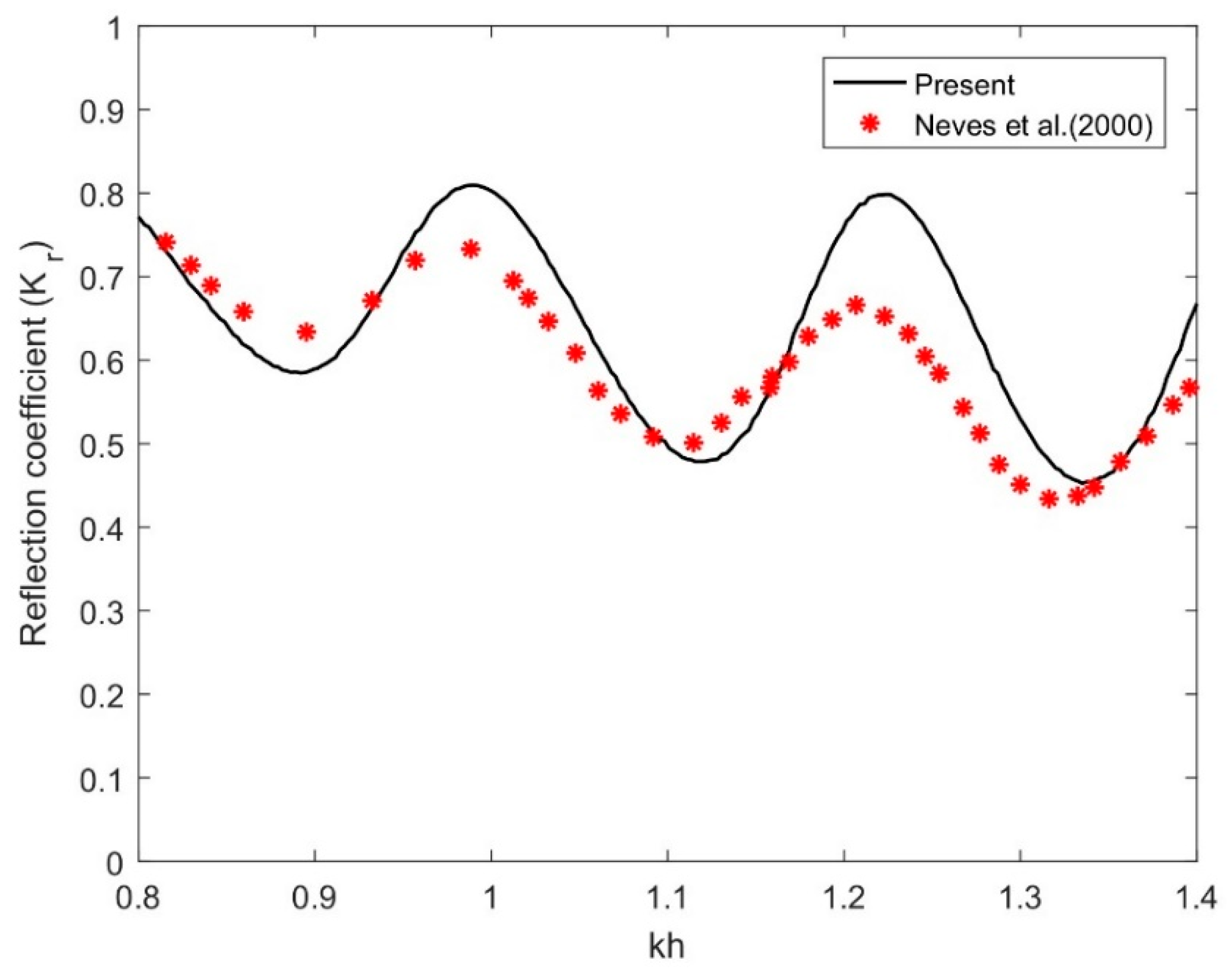
Figure 3 and Figure 4 show the comparisons of reflection coefficient Kr between the present and experimental data as well as analytical results [8] with σ = 0.49, θ = 60 ° , h/a = 0.6, and h / H = 0.25 with flexural rigidity E = 5 × 10 8 GPa , compressive force f c = E I ρ g , and mooring stiffness q = 10 5 Nm 1 versus non-dimensional wavenumber k h . Comparison results indicated that some of the experimental data points and analytical points are agreed well with the present model and others are only agreed in trend, not their values. It is again observed that the trough of the reflection coefficients is almost the same between models, but the crests of Kr in the present result are little far for some non-dimensional wave number. These differences can be explained by the present solution associated with the flexible structure with multi-mode motions and in the presence of compressive force, while these parameters were not included in the model [8]. It is also suspected that the complex wavenumber effects considered in the present model associated with the structural deformations due to the additional features of flexibility with compressive force can play a vital part in the characteristics of the wave phenomena, while these effects were not considered in the model [8]. Therefore, the present model reproduces a higher crest of the reflected wave (which leads to reflection coefficients) that the model [8] cannot reproduce.
From Figure 3 and Figure 4, it is may be concluded that the present reflection coefficient results based on the developed analytical solution are supported by the analytical and experimental dataset [8] in the submerged porous plate model without assuming the flexural rigidity and compressive force.

4.4.2. Effect of Design Parameters on the Hydroelastic Response of a Moored Submerged Horizontal Flexible Plate

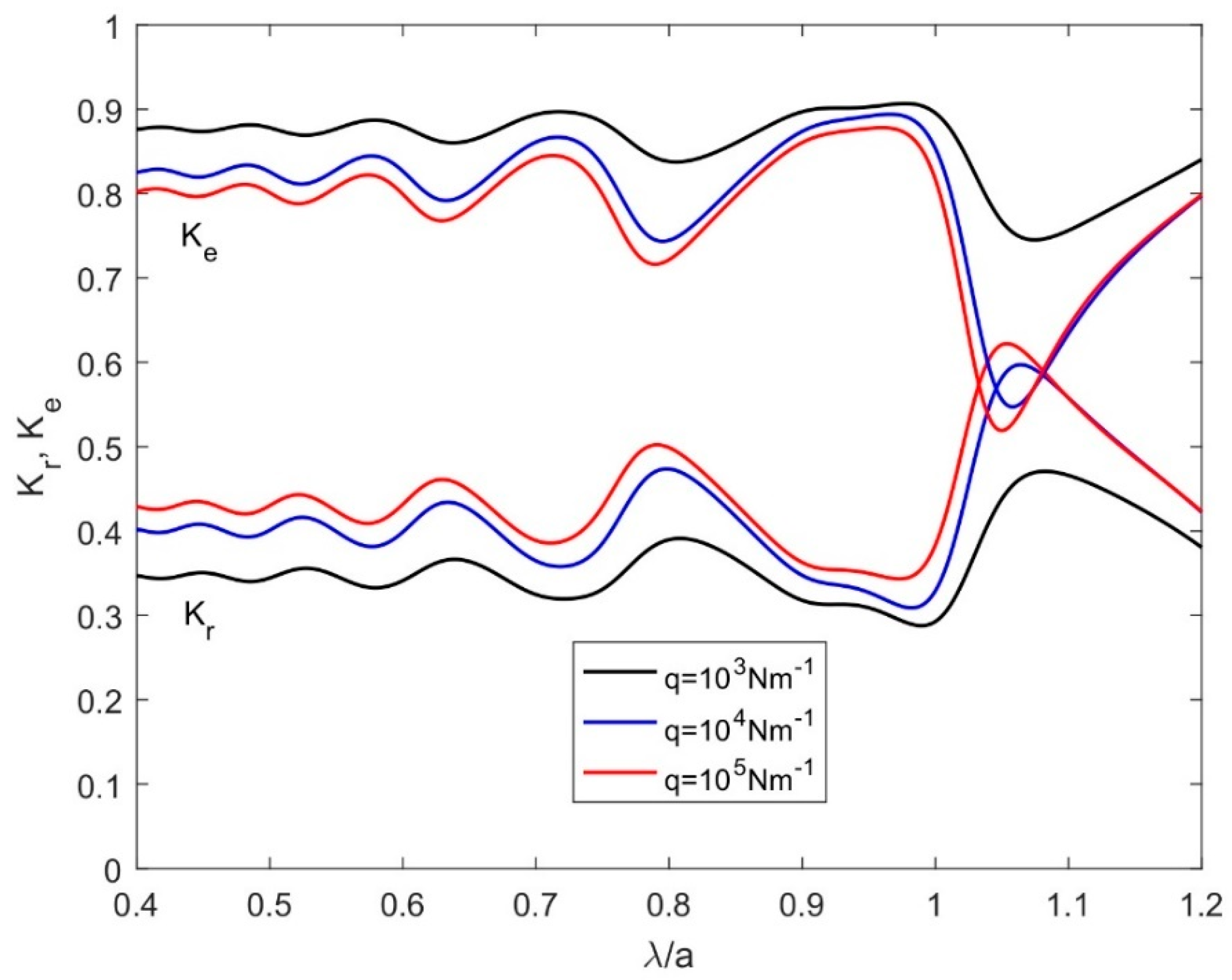
Figure 5 illustrates the variations of K r and K e with various values of mooring stiffness q for θ = 60 ° , E = 5 × 10 8 GPa , f c = E I ρ g , h / H = 0.25 , and σ = 1.0 + 0.5 i against non-dimensional wavelength λ / a . The reflection coefficient K r to be higher as the value of mooring stiffness q increases. Furthermore, the general observations in K r and the reasons are close to [5] in the case of a two-dimensional moored finite submerged porous plate. The dissipation coefficient K e was found to be lower with higher values of mooring stiffness, which is attributed to the structural stiffness. It may be noted that the values of the dissipation coefficients are more than those of reflection coefficients for all values of mooring stiffness. This suggests that the flexible plate dissipates more energy by keeping balance with the mooring lines for a certain value of angle of incidence θ and porous-effect parameter.
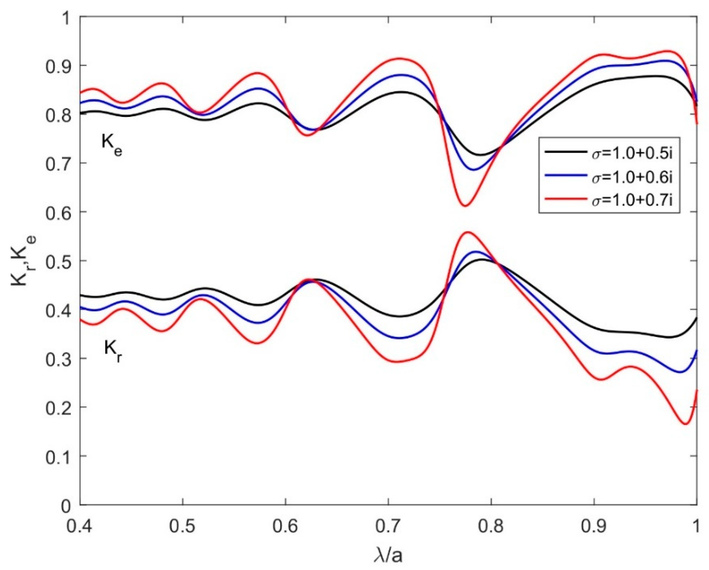
In Figure 6, the variations of K r and K e for various values of σ with θ = 60 ° , E = 5 × 10 8 GPa , f c = E I ρ g , and h / H = 0.25 against λ / a are plotted. For higher values of the porous-effect parameter, the reflection coefficient K r becomes lower and the dissipation coefficient K e increases. This is because the pores over the plate increase, which leads to more wave energy dissipation. Furthermore, for smaller wavelengths, the overall trend of K r and K e are alike as in Figure 5.
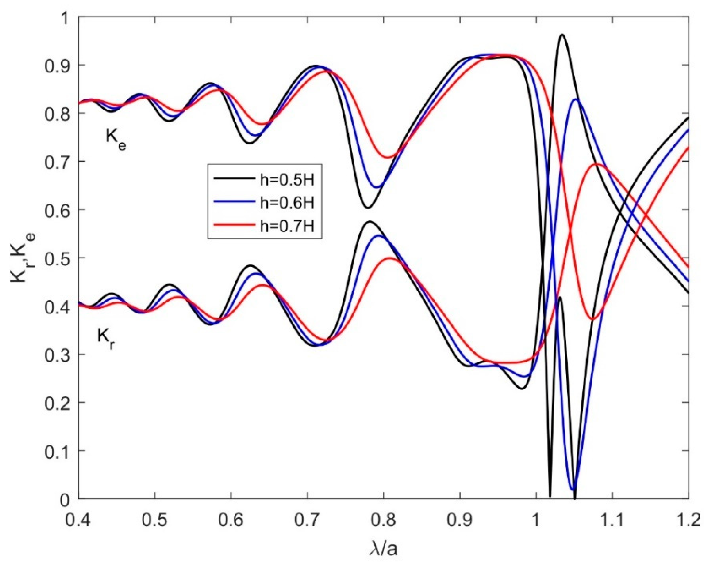
Figure 7 depicts the variations of K r and K e versus non-dimensional wavelength λ / a for various values of submergence depth h / H with θ = 60 ° , E = 5 × 10 8 GPa , f c = E I ρ g , q = 10 5 Nm 1 , and σ = 1.0 + 0.5 i . The results of Figure 7 showed that as h / H increases the values of K r become lower whilst the results in the dissipation coefficients K e are almost alike as in reflection coefficients. This suggests that as the porous plate away from the water surface, the effect of wave energy dissipation lessens.
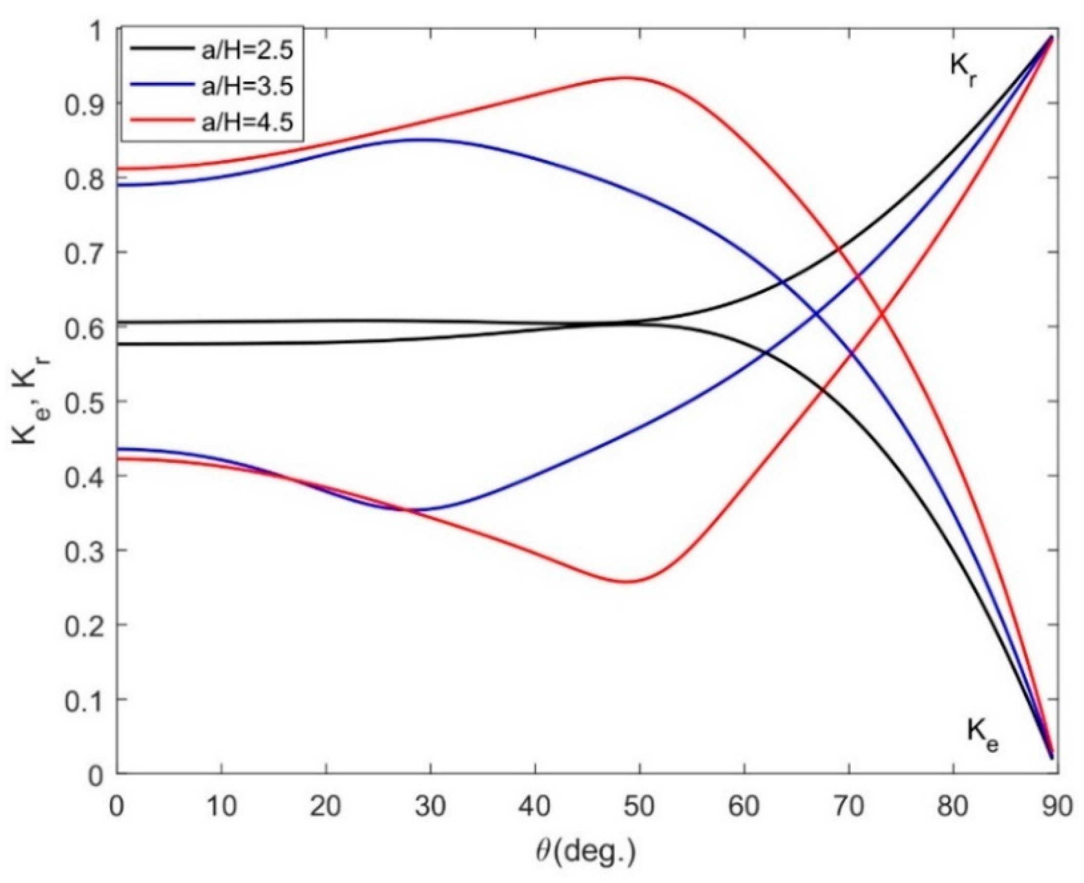
Figure 8 gives the effect of K r and K e on different mooring stiffness q with E = 5 × 10 8 GPa , f c = E I ρ g , h / H = 0.25 , a / H = 2.5 , and σ = 1.0 + 0.5 i against oblique angle θ. In Figure 8, the reflection coefficients K r are to be higher as the values of mooring stiffness increases and the reasons are similar as in Figure 5 whilst the dissipation coefficient K r decreases as the value of q increases (see [2]).
In Figure 9, the effect of K r and K e on different σ are plotted for E = 5 × 10 8 GPa , f c = E I ρ g , h / H = 0.25 , a / H = 2.5 , and q = 10 5 Nm 1 against oblique angle θ. For higher values of q , the K r to be lower and the dissipation coefficients K e become higher. However, the variations of K r and K e for various values of q are negligible for a higher angle of incidence. These observations are similar to [5].
In Figure 10, the variations of K r and K e for various values of h / H against oblique angle are plotted with E = 5 × 10 8 GPa , f c = E I ρ g , a / H = 2.5 , q = 10 5 Nm 1 , and σ = 1.0 + 0.5 i . It is seen that as the submergence depth h / H increases, the value of K r becomes higher and the dissipation coefficient decreases. The reasons are similar as in Figure 7 and the general observations are the same as in [5].
Figure 11 gives that variations K r and K e on different values of non-dimensional structural length a / H for E = 5 × 10 8 GPa , f c = E I ρ g , h / H = 0.25 , σ = 1.0 + 0.5 i , and q = 10 5 Nm 1 against oblique angle θ. For longer structure, K r becomes lower and higher in dissipation coefficients which is due to the largeness of the structural flexibility and pores of the structure that leads a large amount of wave energy dissipated over the flexible plate.
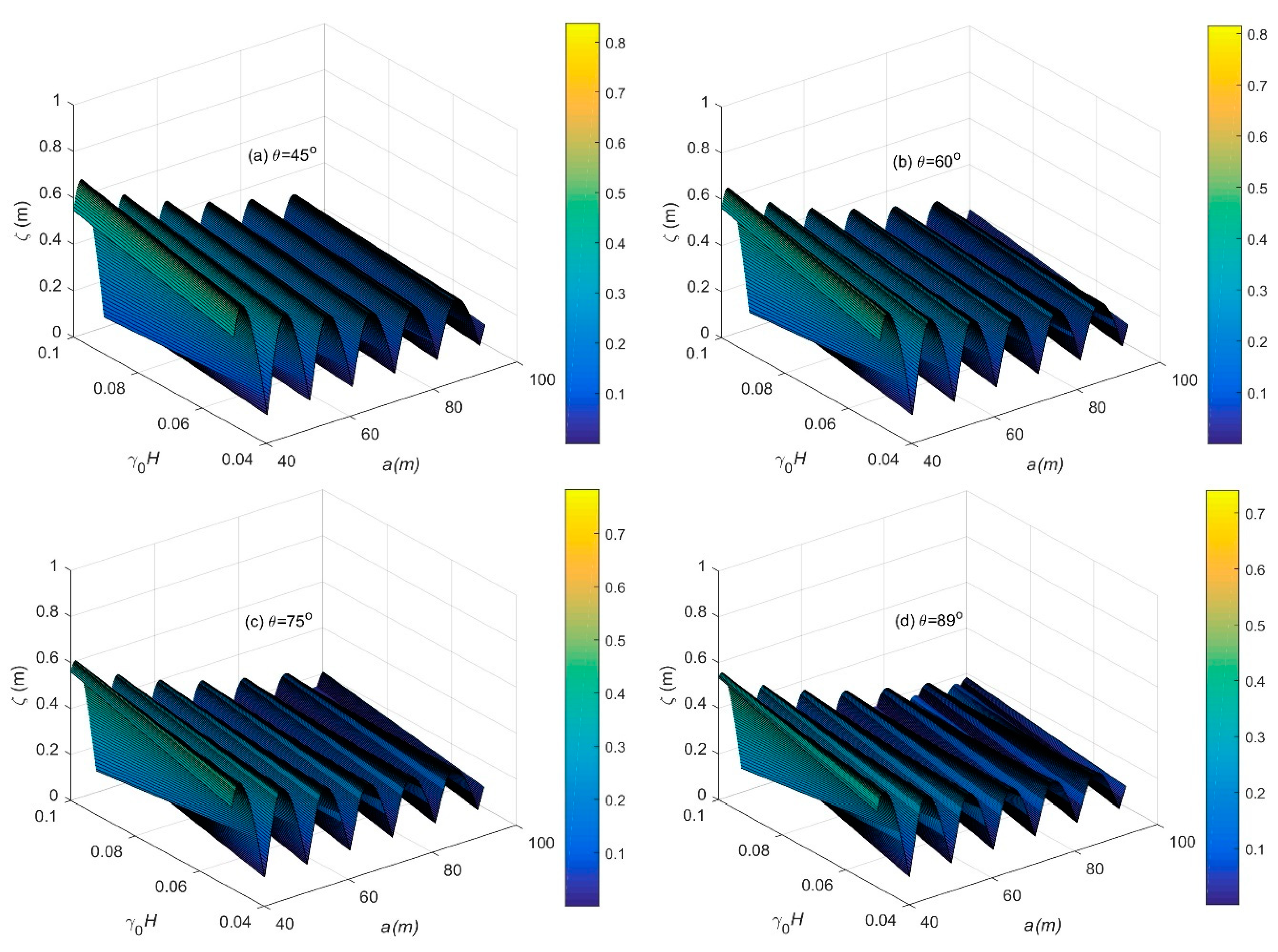
In Figure 12, flexible plate displacements ζ for different oblique angles (a) θ = 45 ° , (b) θ = 60 ° , (c) θ = 75 ° , and (d) θ = 89 ° versus γ 0 H with q = 10 2 Nm 1 , f c = E I ρ g , E = 5 × 10 5 GPa , and h / H = 0.25 are plotted. Figure 12a–d illustrates that the plate deflections are to be lower with higher values of oblique angle θ. A comparison between Figure 12a–c and Figure 12d explains that the number of crests or optima in the plate displacement increases especially in Figure 12d at θ = 89°. This is attributed to the fact that the interaction of waves at the surface mode and waves at the submerged flexural mode which leads to the change of phase which decreases the wave crests and increases the number of the crests in the plate displacements.
Figure 13 shows the displacement ζ of the moored submerged flexible porous plate for different porous-effect parameters (a) σ = 0.2 i , (b) σ = 0.3 i , (c) σ = 0.5 i , and (d) σ = 0.55 i versus γ 0 H and plate length with q = 10 5 Nm 1 , f c = E I ρ g , E = 5 × 10 5 GPa , θ = 60 ° , and h / H = 0.25 . From Figure 13a–d, it is observed that as the values of σ increases the displacements become higher which is seen from their color bars. This is due to the greater amount of wave energy concentrated over the horizontal plate as the pores of the plate increase that leads to a higher wave crest. On the other hand, the number of crests in the plate displacement decreases as the porosity of the plate increases. This indicates that the wave absorption capacity of the flexible porous plate increases when the values of porosity of the plate increase.
It may be mentioned that the numerical computations of the analytical expression were carried out in a desktop machine with Intel® core i7-4790 CPU with a 3.60 GHz processor and 16 GB of RAM. On average, each case was run for roughly 5–7 min (computational time) for different values of N.

5. Conclusions

In this paper, generalized expansion formulae associated with velocity potentials for the aforementioned problem are developed using Green’s function in FD and ID. By utilizing the integral form of Green’s function and identity, the series form of the velocity potentials for the wavemaker problem is derived in FD and ID. The application of the derived expansion formula is illustrated by studying a real problem of a moored flexible plate of finite dimension oblique waves in FD. It has been concluded that:
  • Under oblique waves, the Green’s functions, expansion formulae, and expansion form for the wavemaker problem is derived here in FD and ID which are communicated for the first time.
  • The derived Green’s function can facilitate the analysis of the thin and thick flexible plate, and applications to wavemaker problems over boundary integral equation formulations associated with real physical problems in BEM analysis.
  • The basic limitations of the present approach are (i) relevant boundary conditions must be linear (maybe of higher-order), (ii) structural boundaries must be at constant of co-ordinates (ends of the structure must be at fixed locations), (iii) the coefficients associated with the equations must uncomplicated, and (iv) after all, the solution must be a series of solutions. Therefore, the MEFEM approach can be used for the rectangular and circular shaped flexible plate and membrane type structures.
  • For numerical correctness and convergence of the series solution, in the computation N = 5 is confined.
  • Comparison results show that the present results based on the analytical solution are supported by the published experimental data and as well as analytical results.
  • The analysis of the reflection and the dissipation coefficients indicated that the absorption of wave energy over a flexible plate is remarkable for the suitable value of the oblique angle of the incident wave and mooring stiffness.
  • The study demonstrates that plate displacement reduces with an increase in oblique angle, suitable positing, and appropriate choice of porous-effect parameter.
  • As a result, the present formulation can be further generalized to develop a wave energy converter (WEC)-type attachment for wave energy extraction.

Author Contributions

Conceptualization, S.C.M. and C.G.S.; Methodology, S.C.M.; Writing—original manuscript, S.C.M. and C.G.S. All authors have read and agreed to the published version of the manuscript.

Funding

This work was performed within the project HYDROELASTWEB—Hydroelastic behavior of horizontal flexible floating structures for applications to Floating Breakwaters and Wave Energy Converters, which is funded by the Portuguese Foundation for Science and Technology (Fundação para a Ciência e a Tecnologia—FCT) under contract 031488_770 (PTDC/ECI-EGC/31488/2017). The first author has been contracted as a Researcher by the Portuguese Foundation for Science and Technology (Fundação para a Ciência e Tecnologia-FCT), through scientific employment stimulus, individual support under the contract no. CEECIND/04879/2017. This work contributes to the Strategic Research Plan of the Centre for Marine Technology and Ocean Engineering (CENTEC), which is financed by the Portuguese Foundation for Science and Technology (Fundação para a Ciência e Tecnologia—FCT) under contract UIDB/UIDP/00134/2020.

Conflicts of Interest

The authors declare no conflict of interest.

Abbreviations List

BVPBoundary Value Problem
FDFinite Depth
IDInfinite Depth
MEFEMMatched eigenfunction expansion method
WECWave Energy Converter
BEMBoundary Element Method

Appendix A. Shallow Water Equations

This appendix presents the linearized shallow water equations in a straightforward way based on the assumption of shallow water approximation. The equation of motion takes of the form
( 1 / h ) { ( η / t ) ( ζ / t ) } = U ˜ 2 Φ
and
( 2 η / t 2 ) ( 2 ζ / t 2 ) = g h U ˜ 2 η
where U ˜ 2 being the same as in Equation (1), η ( x , z , t ) and ζ ( x , z , t ) are the wave surface elevation and plate displacement, respectively. Now, the equation of continuity at y = h is given by
( ζ / t ) + i σ ( Φ 2 Φ 1 ) = h 1 U ˜ 2 Φ
Using Equations (4), (A1) and (A2), the shallow water equation in terms of η ( x , z , t ) and ζ ( x , z , t ) is derived as
{ U ˜ 2 ( E I U ˜ 2 + f c ) } [ U ˜ 2 ( ζ / t ) i σ ( / t ) { ( ζ / h 1 ) ξ / h } ] = ρ ( 3 / t 3 ) { ( ζ / h 1 ) ξ / h }
where ξ = ( η ζ ) . Substituting the expressions of η ( x , z , t ) and ζ ( x , z , t ) into Equations (A2) and (A4), one can derive two Equations in terms of sinusoidal wave amplitudes η 0 and ζ 0 as
( ω 2 g h p 2 ) η 0 ω 2 ζ 0 = 0
{ ρ ω 2 i σ ( E I p 4 f c p 2 ) } h 1 η 0 [ { ρ ω 2 i σ ( E I p 4 f c p 2 ) } H p 2 ( E I p 4 f c p 2 ) h h 1 ] ζ 0 = 0
where p 2 = k 2 + φ 2 . Substituting the value η 0 / ζ 0 from Equation (A5) into Equation (A6), the obtained equation will be the shallow water dispersion relation which will be the same as in Equation (14) when p h , p h 1 1 . It should be mentioned that if E I = 0 and f c = T f , then the lessens result will be the same as in [2]. Furthermore, if φ = 0 and both σ = 0 , φ = 0 , then the reduced expression will be the same as in [5,14], respectively.

References

  1. Cho, I.H.; Koh, H.J.; Kim, J.R.; Kim, M.H. Wave scattering by dual submerged horizontal porous plates. Ocean Eng. 2013, 73, 149–158. [Google Scholar] [CrossRef]
  2. Guo, Y.C.; Mohapatra, S.C.; Guedes Soares, C. Wave energy dissipation of a submerged horizontal flexible porous membrane under oblique wave interaction. Appl. Ocean Res. 2020, 94, 101948. [Google Scholar] [CrossRef]
  3. Zheng, S.; Meylan, M.H.; Zhu, G.; Greaves, D.; Iglesias, G. Hydroelastic interaction between water waves and an array of circular floating porous elastic plates. J. Fluid Mech. 2020. [Google Scholar] [CrossRef]
  4. Zheng, S.; Meylan, M.H.; Fan, L.; Greaves, D.; Iglesias, G. Wave scattering by a floating porous elastic plate of arbitrary shape: A semi–analytical study. J. Fluids Struct. 2020, 92, 102827. [Google Scholar] [CrossRef]
  5. Mohapatra, S.C.; Sahoo, T.; Guedes Soares, C. Surface gravity wave interaction with a submerged horizontal flexible porous plate. Appl. Ocean Res. 2018, 78, 61–74. [Google Scholar] [CrossRef]
  6. Li, Z.F.; Wu, G.X.; Shi, Y.Y. Interaction of uniform current with a circular cylinder submerged below an ice sheet. Appl. Ocean Res. 2019, 86, 310–319. [Google Scholar] [CrossRef] [Green Version]
  7. Wu, J.; Wan, Z.; Fang, Y. Wave reflection by a vertical wall with a horizontal submerged porous plate. Ocean Eng. 1998, 25, 767–779. [Google Scholar] [CrossRef]
  8. Neves, M.G.; Losada, I.J.; Losada, M.A. Short-wave and wave group scattering by submerged porous plate. J. Eng. Mech. 2000, 126, 1048–1056. [Google Scholar] [CrossRef]
  9. Liu, Y.; Li, H.J.; Li, Y.C. A new analytical solution for wave scattering by a submerged horizontal porous plate with finite thickness. Ocean Eng. 2012, 42, 83–92. [Google Scholar] [CrossRef]
  10. Evans, D.V.; Peter, M.A. Asymptotic reflection of linear water waves by submerged horizontal porous plates. J. Eng. Math. 2011, 69, 135–154. [Google Scholar] [CrossRef] [Green Version]
  11. Liu, Y.; Li, Y.C.; Teng, B. Wave interaction with a perforated wall breakwater with a submerged horizontal porous plate. Ocean Eng. 2007, 34, 2364–2373. [Google Scholar] [CrossRef]
  12. Liu, Y.; Li, Y. An alternate analytical solution for water-wave motion over a submerged horizontal porous plate. J. Eng. Math. 2011, 69, 385–400. [Google Scholar] [CrossRef]
  13. Cho, I.H.; Kim, M.H. Transmission of oblique incident waves by a submerged horizontal porous plate. Ocean Eng. 2013, 61, 56–65. [Google Scholar] [CrossRef]
  14. Mohapatra, S.C.; Sahoo, T.; Guedes Soares, C. Surface gravity wave interaction with submerged horizontal flexible structures. J. Hydrodyn. Ser. B 2018, 30, 481–498. [Google Scholar] [CrossRef]
  15. Das, D.; Mandal, B.N. Oblique wave scattering by a circular cylinder submerged beneath an ice-cover. Int. J. Eng. Sci. 2006, 44, 166–179. [Google Scholar] [CrossRef]
  16. Sturova, V. Radiation of waves by a cylinder submerged in water with ice floe or polynya. J. Fluid Mech. 2015, 784, 373–395. [Google Scholar] [CrossRef]
  17. Tkacheva, L.A. Oscillations of a cylindrical body submerged in a fluid with ice cover. J. Appl. Mech. Tech. Phys. 2015, 56, 1084–1095. [Google Scholar] [CrossRef]
  18. Guo, Y.C.; Mohapatra, S.C.; Guedes Soares, C. Review of developments in porous membranes and net-type structures for breakwaters and fish cages. Ocean Eng. 2020, 200, 107027. [Google Scholar] [CrossRef]
  19. Losada, I.J.; Silva, R.; Losada, M.A. 3-D non-breaking regular wave interaction with submerged breakwaters. Coast. Eng. 1996, 28, 229–248. [Google Scholar] [CrossRef]
  20. Losada, I.J.; Silva, R.; Losada, M.A. Interaction of non-breaking directional random waves with submerged breakwaters. Coast. Eng. 1996, 28, 249–266. [Google Scholar] [CrossRef]
  21. Losada, I.J.; Petterson, M.D.; Losada, M.A. Harmonic generation past a submerged porous step. Coast. Eng. 1997, 31, 281–304. [Google Scholar] [CrossRef]
  22. Liu, Y.; Li, Y.C.; Teng, B.; Dong, S. Wave motion over a submerged breakwater with an upper horizontal porous plate and a lower horizontal solid plate. Ocean Eng. 2008, 35, 1588–1596. [Google Scholar] [CrossRef]
  23. Cho, I.H.; Kim, M.H. Wave absorbing system using inclined perforated plates. J. Fluid Mech. 2008, 608, 1–20. [Google Scholar] [CrossRef]
  24. Yueh, C.Y.; Chuang, S.H. Wave scattering by a submerged porous plate wave absorber. In Proceedings of the 19th International Offshore and Polar Engineering Conference, Osaka, Japan, 21–26 July 2009. [Google Scholar]
  25. Liu, Y.; Li, H.J. Wave reflection and transmission by porous breakwaters: A new analytical solution. Coast. Eng. 2013, 78, 46–52. [Google Scholar] [CrossRef]
  26. Mohapatra, S.C.; Sahoo, T. Oblique wave diffraction by a flexible floating structure in th epresence of a submerged flexible structure. Geophys. Astrophys. Fluid Dyn. 2014, 108, 615–638. [Google Scholar] [CrossRef]
  27. Mohapatra, S.C.; Ghoshal, R.; Sahoo, T. Effect of compression on wave diffraction by a floating elastic plate. J. Fluids Struct. 2013, 36, 124–135. [Google Scholar] [CrossRef]
  28. Mohapatra, S.C.; Guedes Soares, C. Effect of submerged horizontal flexible membrane on moored floating elastic plate. In Maritime Technology and Engineering 3; Guedes Soares, C., Santos, T.A., Eds.; Taylor & Francis Group: London, UK, 2016; pp. 1181–1188. [Google Scholar]
  29. Mohapatra, S.C.; Guedes Soares, C. Interaction of ocean waves with floating and submerged horizontal flexible structures in three-dimensions. Appl. Ocean Res. 2019, 83, 136–154. [Google Scholar] [CrossRef]
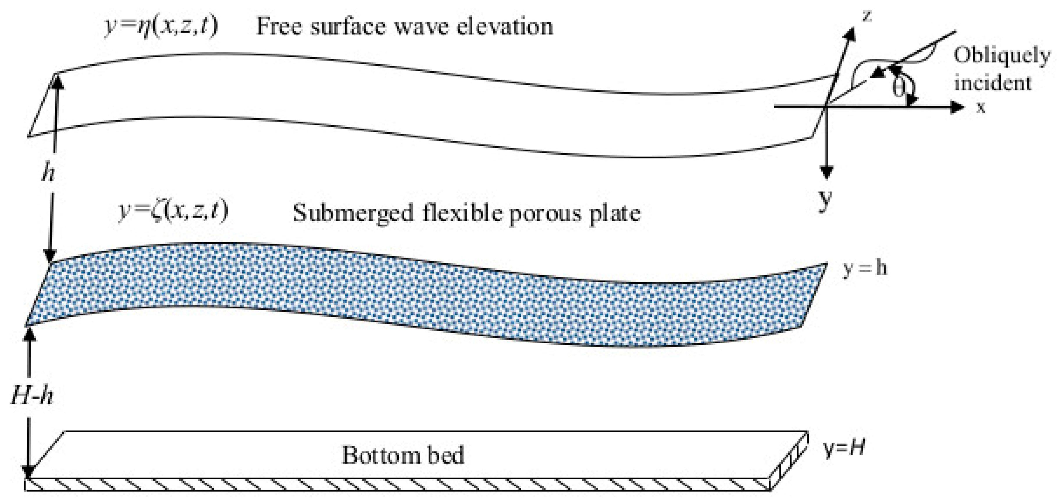
Figure 1. Submerged horizontal porous plate with oblique wave of angle θ.
Jmse 08 00698 g001
Figure 2. Moored submerged horizontally flexible plate with incidence angle θ.
Jmse 08 00698 g002
Figure 3. Reflection coefficients Kr compared with experimental data [8] for σ = 0.49, θ = 60 ° , h/a = 0.6, and h / H = 0.25 with flexural rigidity E = 5 × 10 8 GPa , compressive force f c = E I ρ g , and mooring stiffness q = 10 5 Nm 1 .
Jmse 08 00698 g003
Figure 4. Reflection coefficients Kr compared with analytical results [8] for σ = 0.49, θ = 60 ° , h/a = 0.6, and h / H = 0.25 with flexural rigidity E = 5 × 10 8 GPa , compressive force f c = E I ρ g , and mooring stiffness q = 10 5 Nm 1 .
Jmse 08 00698 g004
Figure 5. Variations of the reflection coefficient K r and the dissipation coefficient K e for different q with θ = 60 ° , E = 5 × 10 8 GPa , f c = E I ρ g , h / H = 0.25 , and σ = 1.0 + 0.5 i .
Jmse 08 00698 g005
Figure 6. Variations of K r and K e for different σ with θ = 60 ° , E = 5 × 10 8 GPa , f c = E I ρ g , h / H = 0.25 , q = 10 5 Nm 1 , and a / H = 2.5 .
Jmse 08 00698 g006
Figure 7. Variations of K r and K e for different submergence depths h / H with θ = 60 ° , E = 5 × 10 8 GPa , f c = E I ρ g , q = 10 5 Nm 1 , and σ = 1.0 + 0.5 i .
Jmse 08 00698 g007
Figure 8. Effect of the reflection coefficient K r and the dissipation coefficient K e on different mooring stiffness q with E = 5 × 10 8 GPa , f c = E I ρ g , h / H = 0.25 , a / H = 2.5 , and σ = 1.0 + 0.5 i .
Jmse 08 00698 g008
Figure 9. Effects of the reflection coefficient K r and the dissipation coefficient K e on different porous-effect parameter σ with E = 5 × 10 8 GPa , f c = E I ρ g , h / H = 0.25 , a / H = 2.5 , and q = 10 5 Nm 1 .
Jmse 08 00698 g009
Figure 10. Variations of K r and K e on different submergence depth h / H with E = 5 × 10 8 GPa , f c = E I ρ g , a / H = 2.5 , q = 10 5 Nm 1 , and σ = 1.0 + 0.5 i .
Jmse 08 00698 g010
Figure 11. Variations of K r and K e for different a / H with E = 5 × 10 8 GPa , f c = E I ρ g , h / H = 0.25 , σ = 1.0 + 0.5 i , σ = 0.5 i , and q = 10 5 Nm 1 .
Jmse 08 00698 g011
Figure 12. Displacement of submerged flexible porous plate ζ versus γ 0 H for (a) θ = 45 ° , (b) θ = 60 ° , (c) θ = 75 ° , and (d) θ = 89 ° with q = 10 5 Nm 1 , f c = E I ρ g , E = 5 × 10 5 GPa , σ = 0.5 i , and h / H = 0.25 .
Jmse 08 00698 g012
Figure 13. Displacement of submerged flexible porous plate ζ for (a) σ = 0.2 i , (b) σ = 0.3 i , (c) σ = 0.5 i , and (d) σ = 0.55 i with q = 10 5 Nm 1 , f c = E I x g , ρ E = 5 × 10 5 GPa , θ = 60 ° , and h / H = 0.25 .
Jmse 08 00698 g013
Table 1. Convergence study of Kr and Ke for various values of the stiffness of mooring lines q , porous-effect parameter σ, and oblique angle θ, with h / H = 0.6 , θ = 60°, q = 102 Nm−1, and wave period T = 5 s.
Parameters N Kr (Reflection Coefficient)Ke (Dissipation Coefficient)
q = 102 Nm−130.37260.8588
50.34670.8774
80.34670.8774
q = 103 Nm−130.37370.8569
50.34700.8761
80.34700.8761
q = 104 Nm−130.43100.8013
50.40280.8245
80.40280.8245
1 + 0.6i30.35190.8738
50.32590.8915
80.32590.8915
1 + 0.8i30.31280.8998
50.28730.9153
80.28730.9153
30°30.40890.8301
50.38390.8498
80.38390.8498
45°30.39100.8446
50.36530.8639
80.36530.8639