Article

Reliability Assurance Dynamic SSC Placement Using Reinforcement Learning

1
School of Control and Computer Engineering, North China Electric Power University, Beijing 102206, China
2
The State Grid Henan Information & Communication Company, Zhengzhou 450052, China
*
Author to whom correspondence should be addressed.
Information 2022, 13(2), 53; https://doi.org/10.3390/info13020053
Submission received: 27 December 2021 / Revised: 17 January 2022 / Accepted: 18 January 2022 / Published: 21 January 2022
(This article belongs to the Topic Big Data and Artificial Intelligence)

Abstract

:
Software-defined networking (SDN) and network function virtualization (NFV) make a network programmable, resulting in a more flexible and agile network. An important and promising application for these two technologies is network security, where they can dynamically chain virtual security functions (VSFs), such as firewalls, intrusion detection systems, and intrusion prevention systems, and thus inspect, monitor, or filter traffic flows in cloud data center networks. In view of the strict delay constraints of security services and the high failure probability of VSFs, we propose the use of a security service chain (SSC) orchestration algorithm that is latency aware with reliability assurance (LARA). This algorithm includes an SSC orchestration module and VSF backup module. We first use a reinforcement learning (RL) based Q-learning algorithm to achieve efficient SSC orchestration and try to reduce the end-to-end delay of services. Then, we measure the importance of the physical nodes carrying the VSF instance and backup VSF according to the node importance of VSF. Extensive simulation results indicate that the LARA algorithm is more effective in reducing delay and ensuring reliability compared with other algorithms.

1. Introduction

For traditional networks, security services are generally implemented by deploying dedicated hardware devices in series or bypassing at the key positions of the network. Dedicated hardware devices are expensive and tightly coupled with the network topology [1]. With the continuous change in network attacks, the disadvantages of this static defense method, such as its poor flexibility, low degree of automation, and low intelligence, are becoming increasingly prominent [2]. In view of this, SDN and NFV technology were created.
SDN is a new technology that separates the data and control planes. The data plane is responsible for data forwarding. The control plane can manage network resources, make configurations more flexible, and dynamically update forwarding rules [3]. NFV uses IT virtualization technology to integrate dedicated network equipment into a generic industry server. It can centrally manage resources and promote resource sharing [4]. The combination of the two technologies provides strong support for exploring new network security service models [5,6]. Network end-to-end security services usually require different types of security service functions and thus, are types of SSC technology based on SDN/NFV.
SSC technology is considered to be a promising and important application field. The SSC is essentially a set of orderly security service functions. It uses NFV technology to virtualize traditional dedicated devices and deploys them on physical nodes. With the help of the centralized management of SDN, traffic is guided to the VSF instance on the physical node in order according to the security service request so as to provide security services for users [7]. The process by which the SSC provides security services can be divided into three phases: chain formation, deployment, and scheduling [8]. The efficient and dynamic deployment of SSC is one of the most challenging issues that must be faced in this field.
SSC technology involves the application of service function chain (SFC) technology in the security field. Much of the existing research in this field focuses on SFC resource allocation for user service requirements in a generic NFV environment [9,10,11,12,13], and very little work is required to embed security services into the cloud data center network. However, the vulnerability of VNF introduces significant challenges to the reliability of SFCs. The factors that lead to VNF failures are complex and diverse. For example, hardware failures associated with processor, memory, storage, and network interface, or software failures associated with host operating systems, hypervisor, virtual machines, and VNF software configuration will cause SFC failures. Although there is some research on SSC, these studies mainly focus on the resource consumption of SSC orchestration [14,15], without considering the low latency and reliability required by security services.
Specifically, the main contributions of this paper can be summarized as follows.
(1)
We take the strict delay constraints of security services and the high failure probability of VSFs into account, and propose the LARA algorithm for an SSC orchestration problem with low latency and high reliability demands.
(2)
We apply AI algorithms to the SSC placement problem and use an RL-based Q-learning algorithm. This speeds up the security service response by reducing the end-to-end delay of the SSC. The end-to-end delay of an SSC defined in this paper includes the VSF processing delay on the substrate node and the transmission delay on the substrate link.
(3)
In the VSF backup phase, we quantify the node importance of VSF and minimize the backup resource overhead on the basis of ensuring the reliability of the SSC.
(4)
We compare the LARA algorithm with three classical algorithms. The simulation results show that the proposed LARA algorithm has a better performance in end-to-end delay and reliability assurance.
The rest of this article is organized as follows. We review related work in Section 1, discuss system models in Section 2, introduce our LARA algorithm in Section 3, conduct experiments and evaluations in Section 4, and finally provide our conclusions in Section 5.

2. Related Work

2.1. Delay-Aware SFC Orchestration

The most important indicator used to measure SSCs’ service quality is the end-to-end delay. In the case of a network attack, the SSC is required to respond quickly and implement security protection so as to minimize the loss. Therefore, in order to ensure the quality of security services, it is necessary to orchestrate the SSC intelligently and efficiently. Since there are few studies on the SSC at present and the SSC is a special form of SFC, we analyzed the existing research on the SFC of delay awareness.
Chua et al. [16] proposed the use of a round-robin scheduling heuristic algorithm for calculating a feasible solution for the resource allocation calculation of the SFC. This solution distributes network traffic between switches on the top of the rack to reduce the use of nodes and minimize the end-to-end delay as much as possible. The designed algorithm is relatively simple and fails to consider the resource constraint conditions for service chain mapping. Taking into account the time-varying nature of the delay parameters of the physical link, Cho et al. [17] designed an online algorithm that can complete the transmission and processing of SFC traffic within the delay threshold. Additionally, Liu et al. [18] constructed the selection of the best deployment location as a 0–1 planning problem, iteratively determined the location of each middleware based on a greedy selection strategy, and used the simulated annealing algorithm to improve the solution within the allowable time. This efficiency of this method depends on neighbor production, temperature management, etc.
Although many achievements have been made in the research of delay-aware SFC scheduling, there are still deficiencies in the research of resource intelligent scheduling in dynamic scenarios. Therefore, it is necessary to use artificial intelligence methods to improve the mapping effect of service chains.

2.2. Reliability Assurance SFC Orchestration

The reliability of the virtual network function is much lower than that of hardware, and any network function failure in the SFC will lead to the failure of the whole chain and service failure. Therefore, studying the SSC orchestration mechanism of reliability assurance is of great significance to the normal operation of security services. The current virtual network function (VNF) backup methods in the literature include dedicated protection backup and shared protection backup [19]. Dedicated backup is used to allocate dedicated physical resources for the VNF to be backed up, while the backup resources are not shared with other VNFs. The backup node will consume the same resources as the main VNF node, meaning that this solution is relatively inefficient. In shared backup, multiple VNFs can share backup resources, which reduces the resource occupation of the backup and makes it more efficient.
Hmaity et al. [20] proposed a redundant backup method, which ensures the availability of services in the event of a single point of failure by backing up the entire service chain. Casazza et al. [21] designed a heuristic strategy based on the use of a greedy algorithm for VNF backup. This strategy can reduce the computational overhead. Wang et al. [22] used the average time between failures and the average available time of the VNF to measure the reliability of the VNF, determine the system backup priority, and back up the most important and second most important VNFs. Hmaity et al. [23] aimed to solve the reliability problem of single-link and single-node failures, weighing the contradiction between delay demand and resource cost as the optimization goal, and proposed the use of three redundant protection strategies and corresponding ILP models to obtain an optimal strategy.
In summary, the existing research on SFC orchestration has the following deficiencies:
  • Deficiencies in intelligent resource scheduling in dynamic scenarios;
  • At present, there is little research on SSC, and there is no joint consideration of the impact of end-to-end delay and reliability on the quality of security services.
In this work, we take the strict delay constraints of security services and the high failure probability of VSFs into account and propose the LARA algorithm for an SSC orchestration problem with low latency and high reliability demands. In the SSC mapping phase, we apply AI algorithms to the SSC placement problem, and use the RL-based Q-learning algorithm. It speeds up the security service response by reducing the end-to-end delay of SSC. In the VSF backup phase, we quantify the node importance of VSF and minimize the backup resource overhead on the basis of ensuring the reliability of the SSC.

3. System Model

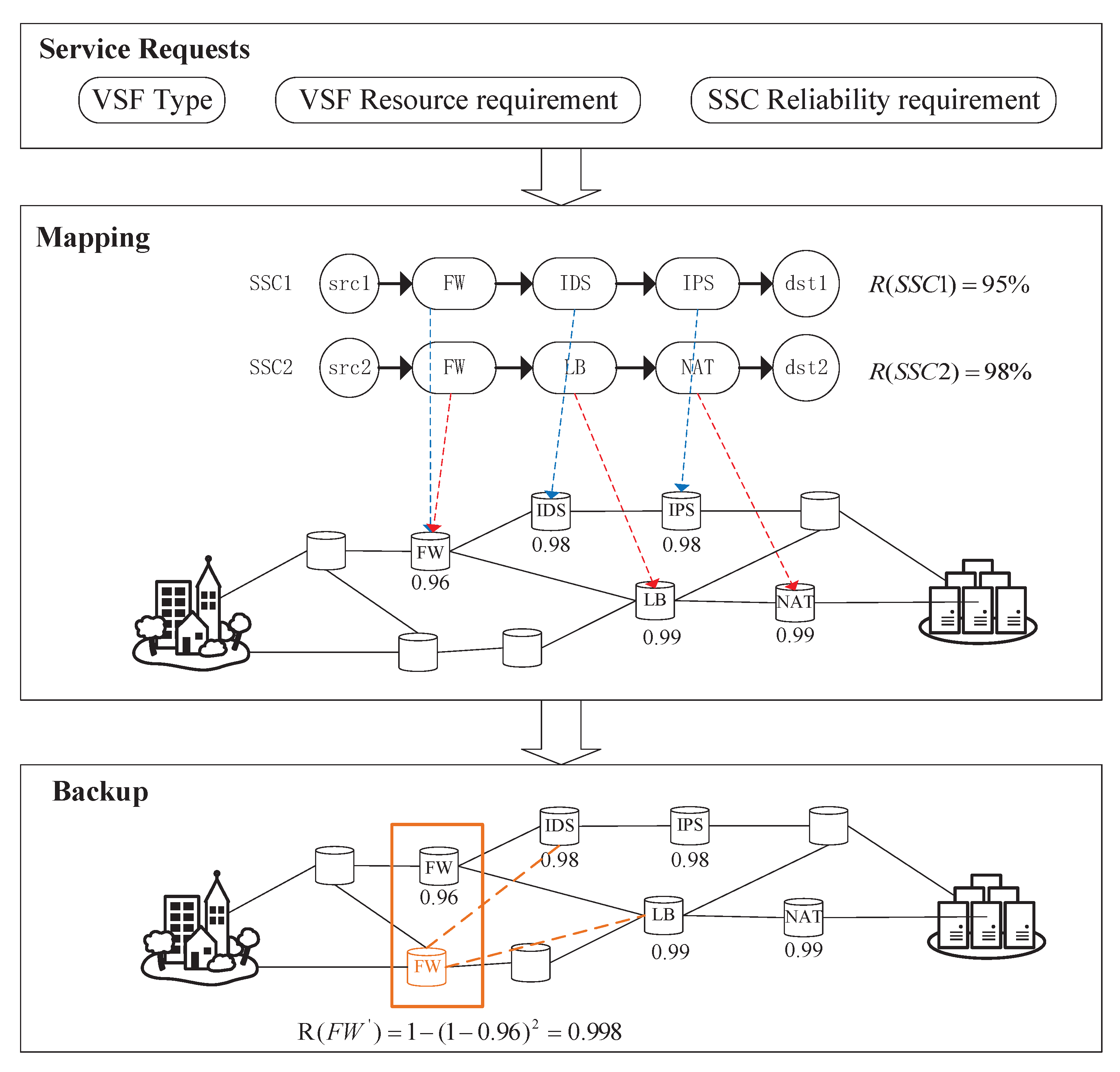
3.1. Problem Description

Figure 1 is a schematic diagram of SSC orchestration for reliability assurance. The SSC requests constructed by users will include VSF type, VSF resource requirement, and SSC reliability requirement. When the system receives the SSC requests, it starts mapping. As shown in Figure 1, the reliability requirements of SSC1 and SSC2 are 95% and 98%, respectively, while the reliability of FW, IDS, and IPS in SSC1 are 0.96, 0.98, and 0.98, respectively. After the orchestration is completed, the reliability of SSC1 is 0.96 × 0.98 × 0.98 = 94.1%; since it does not meet the reliability requirements of SSC1 (95%), the backup phase is started. SSC1 and SSC2 share the physical node carrying the FW instance. Backing up this node can improve the reliability of SSC1 and SSC2 at the same time. After the FW is backed up, the reliability can be increased to R ( F W ) = 1 ( 1 0.96 ) 2 = 0.998 . At this time, the reliability of SSC1 is increased to 0.998 × 0.98 × 0.98 = 95.8%, which meets the reliability requirements of SSC1. Then, the backup node is linked to the SSCs.

3.2. Network Model

3.2.1. Substrate Network

A substrate network is modeled as a weighted undirected graph G s = ( N , E ) (the notation s denotes substrate) in which a substrate node set is represented by N = { n 1 , n 2 , , n X } (the notation X denotes the total number of substrate nodes) and a substrate link set is represented by E = { e i , j | n i , n j N } . Each substrate node n i N , the notation { i c , i m } denotes the available CPU resources and storage resources of the node n i . Additionally, the notation b i , j denotes the available bandwidth resources between node n i and n j .

3.2.2. SSC Request

Let SSC = { S 1 , S 2 , , S c } represent the set of SSC requests in the network. Each SSC request consists of multiple VSFs connected in a specific order. The VSF set is represented by S c = { f 1 c , f 2 c , , f z c } ( z = l e n g t h ( S c ) ) . The notation ω c denotes the reliability requirement of S c . The link between the substrate nodes carrying adjacent VSFs in the SSC is represented by l i ( i + 1 ) c = ( n i c , n i + 1 c ) , while the notation b i ( i + 1 ) c denotes the bandwidth resource requirement of l i ( i + 1 ) c . In the cloud security environment, the VSF may be provided by different vendors, meaning that the reliability of the VSF is different. The notation e r r ( t ) denotes the failure probability of the VSF of type t.

3.3. Modeling

3.3.1. SSC Orchestration

In Table 1, we begin with some necessary notations.
Objective:
Max o b j = R ( S c ) D s u m = k [ 1 , Z ] r ( f k c ) n i N f k c S c A f k c i · D k P + e i , j E l u , v L A l u , v c i , j · D u , v L
Reliability constraints:
r ( f k c ) = A f k c n × ( 1 e r r ( f k c ) ) × t ( A f k c n = 1 )
Equation (1) maximizes the ratio of SSC reliability and delay. The premise for SSC to provide reliable security services is that all security functions in the service chain can operate normally. Therefore, the reliability of S c is k [ 1 , Z ] r ( f k c ) , f k c S c . The total delay includes the VSF processing delay on the substrate node ( n i N f k c S c A f k c i · D k p ) and the transmission delay on the substrate link ( e i , j E l u , v L A l u , v c i , j · D u , v L ). Equation (2) calculates the reliability of VSF f k c , and its value is related to the deployment location and the number of backups.

3.3.2. VSF Backup

Objective:
Min b a c k u p cos t = n i N f k c S c B f k c × ( ( c s c ( n i ) + m s c ( n i ) ) + ( l i p r e · b p r e + l i p o s t · b i ) )
Reliability constraints:
R ( S c ) ω c
R ( S c ) = k [ 1 , Z ] r ( f k c ) = k [ 1 , Z ] A f k c i × B f k c × 1 e r r ( f k c ) C f k c
Placement constraints:
A f k c i + A f k c i 1
Equation (3) minimizes the total resource consumption of the backup. The total backup cost includes the node resource cost and the link resource cost. The cost of node resources is the sum of the CPU resources c s c ( n i ) and storage resources consumed m s c ( n i ) when the VSF is deployed on the node. The cost of link resources is the bandwidth resources consumed by the backup link when the backup VSF is connected to the SSC to which the original VSF belongs. Equation (4) guarantees that for each SSC, the reliability requirements ω c will be met after backup. Equation (5) calculates the SSC S c ’s reliability after backup; the value of R ( S c ) is related to the deployment location of f k c in the orchestration phase and the number of backups C f k c in the backup phase. Equation (6) ensures that the backup VSF is not deployed on the same substrate node as the original VSF to avoid simultaneous failure when the substrate node fails.

4. Algorithm Description

4.1. Algorithm Introduction

This section proposes a SSC orchestration algorithm with a low latency and reliability assurance. The algorithm includes an SSC orchestration module and VSF backup module. The flow chart of the algorithm is shown in Figure 2.
Firstly, we input the substrate network G s = ( N , E ) and the SSC request set SSC = ( S 1 , S 2 , , S c ) . Secondly, we call the SSC orchestration module, perform SSC mapping based on the Q-learning algorithm, and output the result set O = ( O 1 , O 2 , , O c ) . Thirdly, we place the SSC whose reliability does not meet the requirements in set ω S S C . Finally, we call the VSF backup module to process the SSC in set ω S S C until the reliability of all SSCs is satisfied and the algorithm ends.

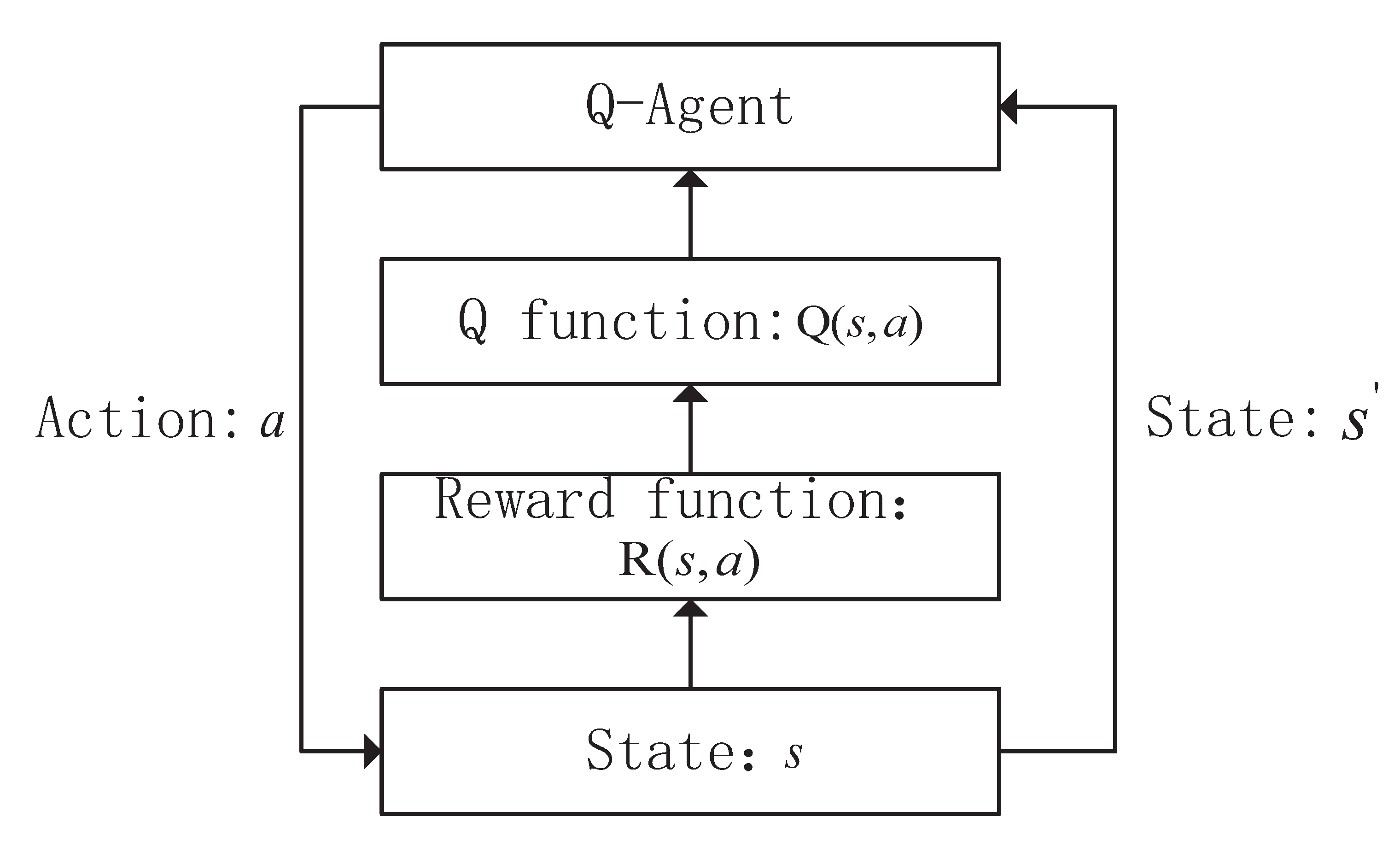
4.2. SSC Mapping Based on Q-Learning Algorithm

4.2.1. Q-Learning Model

Existing studies usually use linear programming techniques to orchestrate the service chain [7]. However, in actual scenarios, the physical network topology is often large in scale and the linear programming method takes a long time to solve the optimal solution for the orchestration and deployment of the dynamically reached SSC [24]. In order to achieve efficient SSC orchestration, this paper applies RL technology and proposes an SSC orchestration method based on the Q-learning algorithm.
The Q-learning algorithm model is shown in Figure 3. The Q-learning algorithm usually solves complex decision optimization problems with less prior knowledge [25]. The agent Q agent first senses the environment state selects an action a, and executes it according to the Q function on the basis of the current state s. When moving to the next state s , the agent calculates the reward function R ( s , a ) and updates the Q function Q ( s , a ) based on the environmental feedback, then selects the next action based on the new Q value and the current environmental state and iteratively proceeds until the optimal strategy is obtained [26].
We define the environment state set, the action set, and the reward function as follows:
A.
Environment state set
The state set is the set of information that the Q agent receives from the environment to take an action that will return a given reward in the long run. The environment state set can be represented by the available resources of the substrate nodes and the available bandwidth of the substrate links at present. Assuming that the CPU and memory resources required by different types of VSFs can be simulated by the sum of several normal distributions, these resources are randomly sampled at different time points to represent the resource consumption status of the substrate nodes. The state set is composed of three components, as defined by Equation (7).
s t a t e = { { 1 c , 2 c , , X c } , { 1 m , 2 m , , X m } , { b i , j } }
where X represents the number of substrate nodes in the network; X c is the current CPU resource status of node X; X m is the current memory resource status of node X; and b i , j is the current bandwidth resource status of the substrate link e i , j .
B.
Action set
The action set is a vector that defines a unique action that the Q agent can take at a given time t. In this paper, the action is the SSC placement decision for each VSF. There are X nodes in the substrate network and each action corresponds to a node; thus, there are X actions in the action set. Equation 8 shows the action set used in this study.
action { 1 , 2 , , X }
In each effective decision, only one VSF should be mapped in a time step, and then the agent should observe the state transition in the state space. Once the current VSF mapping is completed, the next VSF mapping will continue.
C.
Reward function
The reward is a signal that the Q agent receives from the environment after taking an action in a specific state. Based on the reward value, the agent learns the best policy to follow during training. The SSC’s delay is used as a measure of the reward function, including the sum of the VSF processing delay on the substrate node and the transmission delay on the substrate link. We assume that the substrate path between VSFs follows the shortest path first protocol. Equation (9) shows the calculation of the total delay. The reward is calculated as Equation (10). Equation (11) shows the cumulative reward, where λ is the discount factor.
Delay = n i N f k c S c A f k c i · D k P + e i , j E l u , v L A l u , v c i , j · D u , v L
r = 1 / ( Delay + 1 )
R t = t = 1 γ k r t + k + 1
Assuming that the current system state is s and the selected action is a, the selected action needs to satisfy Equation (12). Based on the current state s, we make a decision in ε g r e e d y manner—that is, under a small probability ε , the agent will randomly choose one of all legal actions, while under the probability of 1 ε , the agent will choose the largest action according to Equation (12) so as to avoid being stuck in a state local optimum. After executing the action, the system will enter the next state s . At the same time, feedback r ( s , a ) is obtained according to Equation (10). After this, the Q matrix needs to be updated according to Equation (13).
Q ( s , a ) = max a { Q ( s , a ) }
Q ( s , a ) = Q ( s , a ) + α [ r ( s , a ) + γ max a · Q ( s , a ) Q ( s , a ) ]

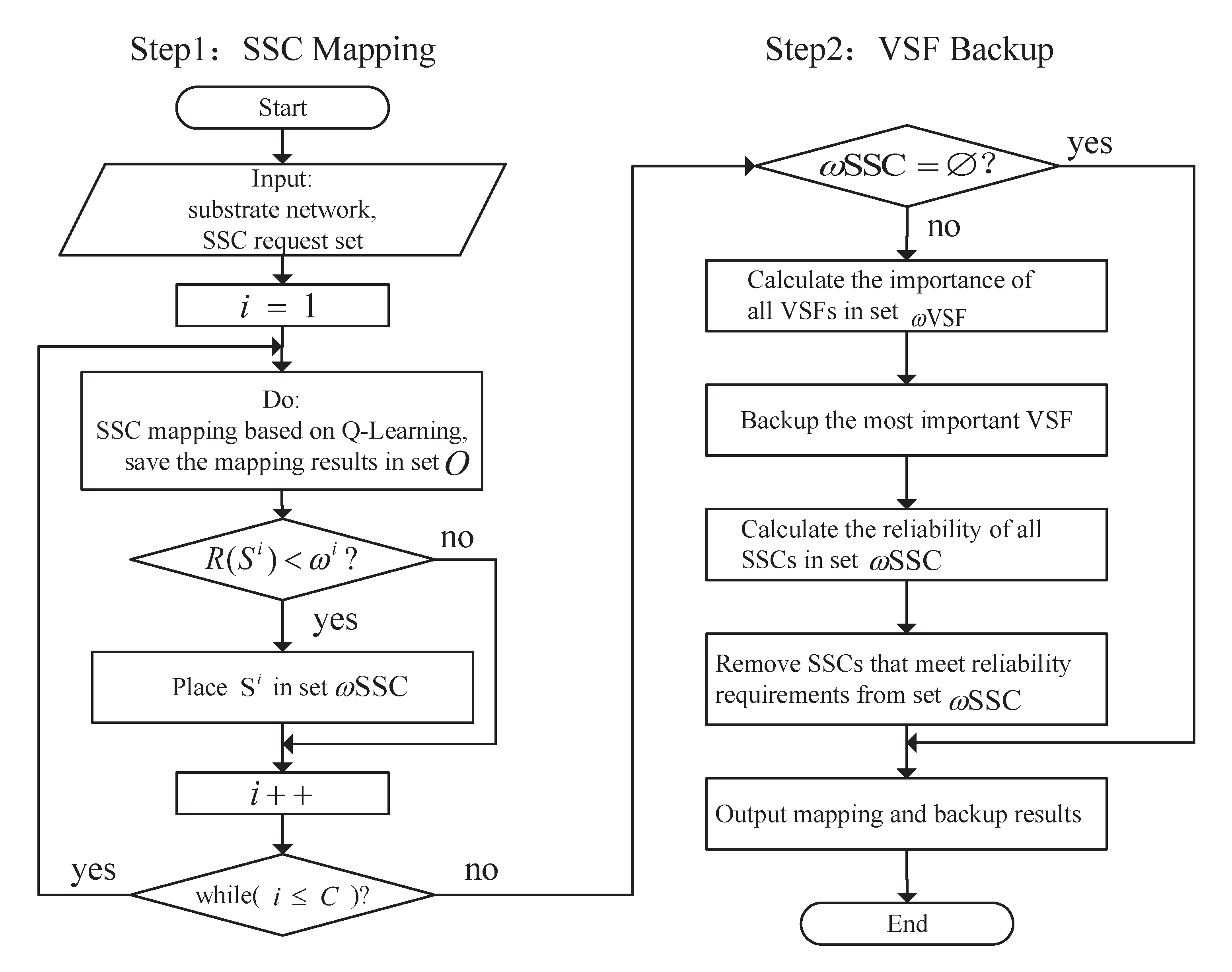
4.2.2. Algorithm Procedure

The whole procedure of the SSC mapping is as shown in Algorithm 1 and the whole procedure of Q-table training is as shown in Algorithm 2.
Algorithm 1: Q-Learning Algorithm for SSC mapping
Input: Substrate network graph G s = ( N , E ) ,
SSC request SSC = { S 1 , S 2 , , S c } .
Output: Orchestration result set O = { O 1 , O 2 , , O c } .
01: Initialize the learning factor α and discount factor λ ;
02: for each request S c S S C , do
03:   if the available substrate network resources meet the needs of S c , then
04:      select a substrate node as the starting point of S c randomly
           and define the current state s = s 0 .
05:      while VSF( f k c S c ), do
06:         deploy f k c on the substrate node in the current state s.
07:         if using the ε g r e e d y strategy to select the next action,
08:            select action a from the action set randomly.
09:         else
10:            select action a according to Equation (12).
11:         end if
12:         execute action a to obtain the next state s .
13:         update the Q table using Equation (13).
14:          s = s .
15:      end while
16:   else
17:      refuse request S c .
18:   end if
19:   update O.
20: end for
21: return O.
Algorithm 2: Q-table training
Input: Substrate network graph G s = ( N , E ) ,
SSC request SSC = { S 1 , S 2 , , S c } .
Output:Q-table.
01: Initialize the learning factor α and discount factor λ ;
02: Initialize Q ( s , a ) = 0 , s s t a t e , a a c t i o n ;
03: for each episode,do
04:   while  S c S S C , do
05:      use Algorithm 1 to orchestrate S c .
06:   end while
07:   update Q-table
08:   restore the substrate network state.
09: end for
10: return Q-table.

4.3. VSF Backup

4.3.1. Node Importance of VSF

This section measures the importance of the physical nodes carrying the VSF instance and backup VSF with a higher importance until the reliability of all SSCs is satisfied. After backing up a VSF, we define the improvement of the SSC reliability as follows:
S P f k c c = R ( S c ) / ω c , R ( S c ) < ω c 1 , o t h e r s
where R ( S c ) is the reliability of S c after backing up the VSF f k c , and S P f k c c is the ratio of R ( S c ) to its target reliability ω c . It can be seen from Equation (14) that if the reliability of S c is satisfied by backing up the VSF f k c , the value of R ( S c ) is 1; otherwise, it is less than 1.
We use M o N f k c to represent the node importance of the VSF f k c ; this can be calculated using Equation (15).
M o N f k c = e c [ 1 , C ] S P f k c c 1 e ( ( c s c ( n i ) + m s c ( n i ) ) + ( l i p r e · b p r e + l i p o s t · b i ) ) + 1
The numerator is the increase in the reliability of all SSCs in set ω S S C after backup; the denominator is the backup resource overhead. When the reliability of all SSCs in set ω S S C is satisfied, the numerator of M o N f k c reaches the maximum value of 1.

4.3.2. Algorithm Procedure

The whole procedure of the VSF backup is as shown in Algorithm 3. Firstly, we calculate the reliability of all SSCs in the result set O = { O 1 , O 2 , , O c } . If SSC O c does not meet reliability requirement ω c , we will put O c in set ω S S C and put all the VSF f k c that makes up SSC O c into set ω V S F . Then we calculate the node importance of all VSFs in set ω V S F and backup VSF with the largest M o N f k c value. After backup VSF, we recalculate the reliability of all SSCs in set ω V S F . If SSC O c meets reliability requirement ω c , we will delete the SSC O c and all the VSF f k c that makes up SSC O c from set ω S S C and set ω V S F , respectively. Finally, we judge whether set ω S S C is an empty set. If ω S S C , we will repeat the above steps; otherwise it means that the reliability of all SSCs is met and the algorithm ends.
Algorithm 3: VSF backup based on node importance
Input: Orchestration result set O = { O 1 , O 2 , , O c } .
Output: VSF backup results.
01: for each SSC O c O , do
02:   calculate the reliability of O c .
03:   if  R ( O c ) ω c , then
04:      put O c in ω S S C ,
           put all the f k c that makes up O c into ω V S F
05:   end if
06: end for
07: while  ω S S C , do
08:   backup f k c with the largest M o N f k c value
09:   for each SSC S c ω S S C , do
10:      calculate the reliability of S c
11:      if  R ( S c ) ω c , then
12:         delete S c from ω S S C
13:      end if
14:   end for
15: end while
16: return VSF backup results.

5. Evaluation

5.1. Simulation Setup

This section uses Python to build the environment for simulation, which includes four modules: a substrate network building module, an SSC request generation module, an SSC mapping module based on the Q-learning algorithm, and a VSF backup module.
We use the Brite topology generator to generate a network topology with 1000 substrate nodes and several links. The CPU resources, storage resources, and link bandwidth resources of substrate nodes are randomly distributed in [40, 90]. The number of VSFs contained in each SSC is randomly distributed in [2, 4]. The VSF processing delay on the substrate node is randomly distributed in [0.2, 0.5] and the transmission delay on the substrate link is randomly distributed in [0.1, 0.4]. According to the service level consensus of Google applications, the reliability requirements of each SSC in the simulation experiment are selected from this set: [95%, 98%, 99%, 99.5%, 99.9%] [27]. The arrival of the SSC requests follows a Poisson process with a constant arrival rate λ . The lifetime of SSC requests follows an exponential function with rate 1 / μ , where μ is the average lifetime.

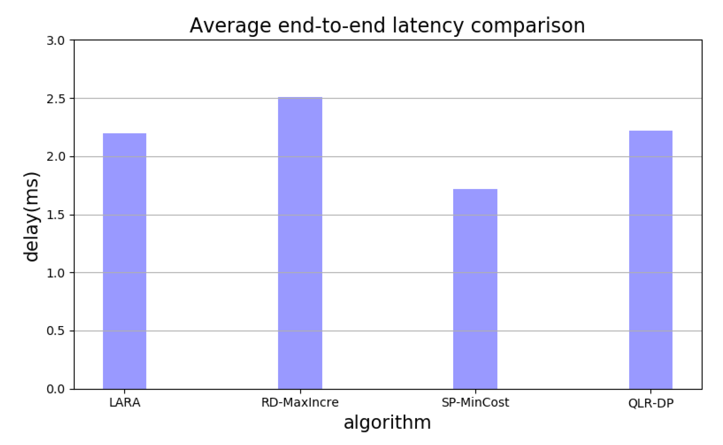
5.2. Results and Discussion

According to the method described in Section 3.2.2, we initialize the model. The simulation and experimental parameters are summarized in Table 2.
After every 60 learning rounds of the agent, the greedy coefficient e decreases by 0.1. After 300 learning rounds, the agent will completely adopt the greedy strategy. The overall training process takes 38.49 s, and the convergence process is shown in Figure 4. In Figure 4, the horizontal axis represents the number of learning rounds of the agent, and the vertical axis represents the average time steps, when each learning round reaches the minimum end-to-end delay of SSCs.
To further demonstrate the effectiveness of the proposed LARA algorithm, we compare our proposed algorithm with three other algorithms. The details are as follows.
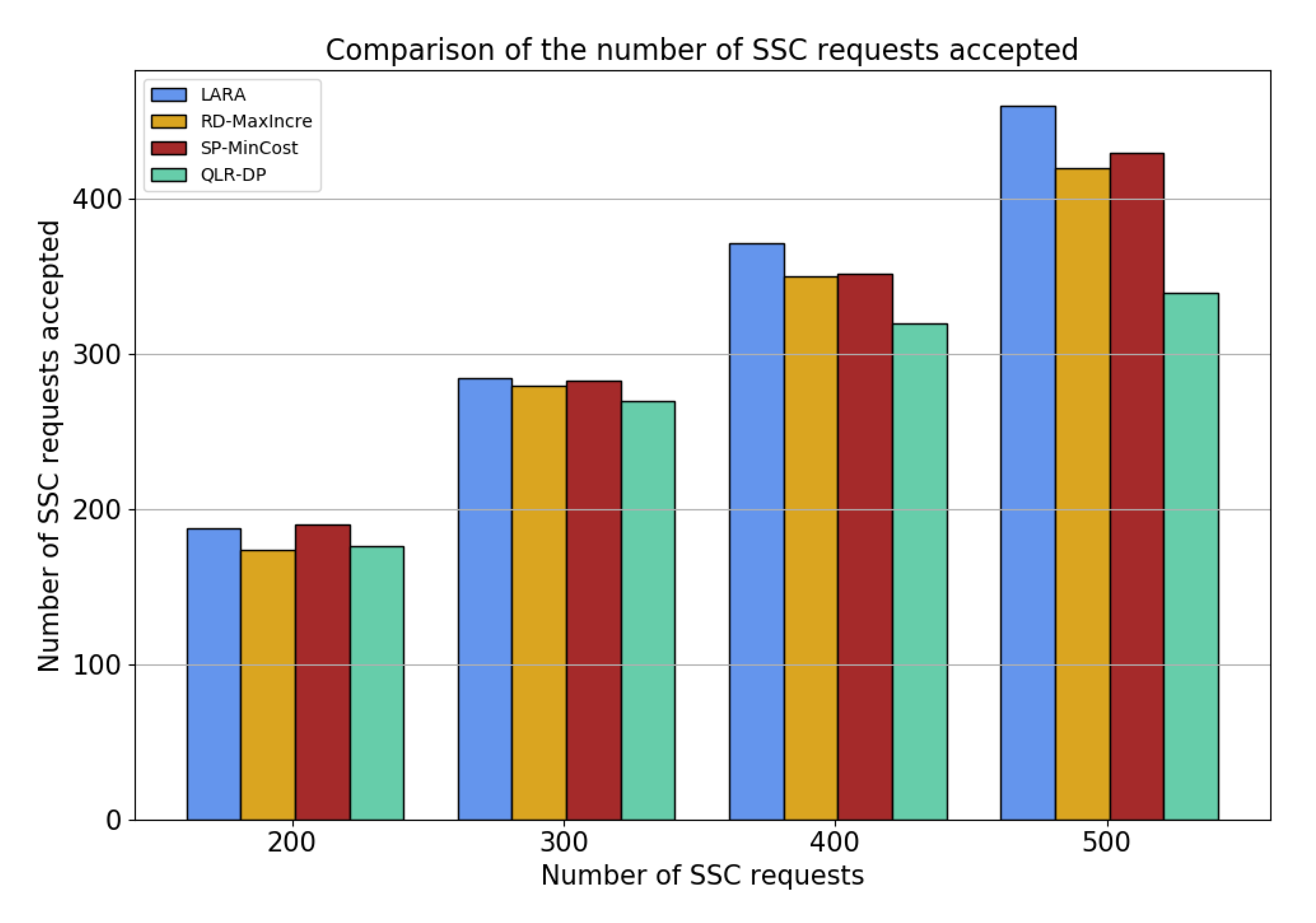
  • RD-MaxIncre: The orchestration step randomly selects substrate nodes to place the VSF. In the backup step, each iteration selects the VSF with the lowest reliability on the SSC in the model for backup so as to achieve the goal of maximum SSC reliability increment and finally heuristically solve the redundant backup scheme.
  • SP-MinCost: The orchestration step adopts the short path algorithm based on the greedy algorithm to directly calculate the shortest path between user endpoints as the basic path for data flow forwarding, then deploys VSF on the substrate node of the path. In the backup step, each round of iteration selects the VSF with the smallest physical resource demand on the SSC in the model for backup so as to achieve the goal of minimizing the backup cost used in each round, before finally heuristically solving the redundant backup scheme.
  • QLR-DP: The orchestration step adopts SSC mapping based on the Q-learning algorithm proposed in this paper. The backup step adopts a dedicated backup, and the VSF with the lowest reliability on each SSC is backed up by multiple SSCs regardless of the sharing of the VSF.
The obtained simulation results and the corresponding analysis are as follows.
(1)
METRIC1: average end-to-end latency.
In this experiment, we simulated 300 SSC requests and deployed them using four algorithms. Figure 5 shows the average end-to-end latency of the SSCs. The total delay of an SSC includes the sum of the VSFs’ processing delay on the substrate nodes and the transmission delay on the substrate links. Generally, we can observe in Figure 5 that the SP-MinCost algorithm has the shortest average end-to-end latency (1.72 ms), while the RD-MaxIncre algorithm has the longest (2.51 ms). The reason for this is that the SP-MinCost algorithm forwards the data flow through the shortest path between the substrate endpoints. However, network resources are limited. The SP-MinCost algorithm will cause the SSC requests to be centrally deployed on a few shortest paths, making it is easy to lead to link congestion and reduce service performance. The LARA algorithm and QLR-DP algorithm both adopt the Q-learning algorithm in the orchestration step, which is as close to the minimum delay as possible in the process of searching for the optimal solution. VSFs are dynamically deployed to near-optimal nodes and obtain a good effect.
(2)
METRIC2: resource consumption.
This experiment compares the average number of backup VSFs for a single SSC and the total backup overhead when backing up with different algorithms under different reliability requirements of the SSC. In this experiment, we simulated 300 SSC requests and the reliability requirements took the following five target values: 95%, 98%, 99%, 99.5%, and 99.9%.
In Figure 6, the abscissa is the reliability requirement and the ordinate is the average number of backup VSF for a single SSC. Figure 6 compares the backup performance of different algorithms for a single SSC. With the increase in the reliability requirements, the number of VSFs needed for a single SSC backup increases gradually for all four algorithms. As shown in Figure 6, under the same reliability requirement condition, the average number of backup VSFs for a single SSC needed by the QLR-DP algorithm becomes much larger than that of the other three algorithms. The reason for this is that the VSF backup of the QLR-DP algorithm is based on a single SSC, ignoring the situation where a single VSF can be shared by multiple SSCs, meaning that the reliability improvement of the backup shared VSF on other SSCS is not taken into account. Among the other three algorithms, the incremental number of backup VSF of the RD-MaxIncre algorithm is the most obvious with an improvement in the reliability requirements. This is because, after the improvement of the reliability requirements, the efficiency of the RD-MaxIncre algorithm in improving the reliability requirements gradually decreases and the algorithm convergence speed is slow.
Figure 7 compares the total backup cost of different algorithms; the abscissa is the reliability requirement and the ordinate is the total backup cost. It is easy to see that the backup cost of all algorithms increases with the increase in the reliability requirements. However, under the same reliability requirement, the total backup cost of the LARA algorithm is the lowest. Although the SP-MinCost algorithm selects the VSF resource requirement for every backup, the reliability increase brought about by these backup VSFs may not be large, which will cause more VSFs to be backed up and consume more substrate resources. Although the RD-MaxIncre algorithm selects the least reliable VSF for backup every time, the substrate resource consumption caused by these VSFs may not be the smallest.
(3)
METRIC3: request acceptance rate.
The reliability requirements of security services may not be met due to the limitation of substrate resources. In this experiment, the SSC reliability requirements are set at 98%, and the security service acceptance of the four algorithms is simulated in the case of 200, 300, 400, and 500 SSCs so as to measure the security service quality.
Figure 8 shows the number of SSC request acceptances of the four algorithms, and Figure 9 shows the SSC request acceptance rate of the four algorithms. The abscissa of Figure 8 and Figure 9 indicate the number of service requests: the ordinate of Figure 8 indicates the number of SSCs that are successfully deployed and meet reliability requirements, and the ordinate of Figure 9 indicates the acceptance rate of SSC requests. It can be seen that the experimental results of the LARA, RD-Maxincre, and SP-Mincost algorithms are similar, while the request acceptance rate of the QLR-DP algorithm is lower. The reason for this is that the first three algorithms all use shared backup in the backup step. As the number of SSC requests increases, the number of SSCs accepted also increases gradually. This is because the substrate resources are gradually used in full, meeting the reliability requirements of more SSCs and meaning that more SSCs are accepted. When the number of SSC requests is the same, LARA’s acceptance rate is always higher than 90%. However, the lowest acceptance rate of the QLR-DP algorithm is 68% when the number of SSCs is 500, while the highest rate is 90% when the number of service requests is 300. This is because the QLR-DP algorithm uses dedicated backup, occupying a large number of physical nodes and resulting in insufficient underlying resources, which ultimately means that the SSC reliability cannot be met, leading to it being rejected in large numbers.

6. Conclusions

Considering the dynamic nature of cloud data center networks, determining the mapping and backup of VSFs to ensure the quality of security services is a challenging problem, particularly without violating the security resource utilization constraints and security service requirements.
In view of the strict delay constraints of security services and the high failure probability for VSFs, this paper proposes an SSC orchestration algorithm that is latency aware with reliability assurance. Firstly, we use an RL-based Q-learning algorithm to select the appropriate VSF placement, realize efficient SSC orchestration, reduce end-to-end delay, and ensure the quality of the service. Then, we measure the importance of the physical nodes carrying the VSF instance and backup VSF with a higher importance to minimize the cost of backup resources on the basis of ensuring the reliability of the SSC. Finally, we compare three classical algorithms. The simulation results show that the proposed LARA algorithm has better performance in end-to-end delay and reliability assurance. We are still exploring how to combine our proposed LARA algorithm with some machine-learning-based approaches (e.g., GNN [28,29], MLP [30]), which can forecast the future trends of link/node load and traffic variations ahead of time, and thus improve the efficacy of the SSC resource allocation algorithm.

Author Contributions

Conceptualization, W.L. and Y.J.; methodology, W.L. and Y.J.; software, Y.J., Q.F. and H.W.; validation, Y.J., Q.F. and H.W.; investigation, F.D., F.G. and Y.J.; resources, F.D., F.G. and X.Z.; data curation, F.D., F.G. and X.Z.; writing—original draft preparation, Y.J.; writing—review and editing, W.L., X.Z., F.D., F.G., Q.F. and H.W.; visualization, Y.J.; supervision, W.L. and X.Z.; project administration, W.L.; funding acquisition, X.Z. and F.D. All authors have read and agreed to the published version of the manuscript.

Funding

This work was financially supported by the science and technology project of State Grid Henan Electric Power Company: “Research and application of key technologies of adaptive protection for State Grid Cloud Security” (Grand No. SGHAXT00YJJS2100034).

Institutional Review Board Statement

Not applicable.

Informed Consent Statement

Not applicable.

Data Availability Statement

Not applicable.

Conflicts of Interest

The authors declare no conflict of interest.

Abbreviations

The following abbreviations are used in this manuscript:
VSFVirtual Security Function
SSCSecurity Service Chain
VNFVirtual Network Function
SFCService Function Chain
RLReinforcement Learning

References

  1. Luizelli, M.C.; Bays, L.R.; Buriol, L.S.; Barcellos, M.P.; Gaspary, L.P. Piecing together the NFV provisioning puzzle: Efficient placement and chaining of virtual network functions. In Proceedings of the 2015 IFIP/IEEE International Symposium on Integrated Network Management (IM), Ottawa, ON, Canada, 11–15 May 2015; pp. 98–106. [Google Scholar]
  2. Feng, B.; Zhou, H.; Li, G.; Zhang, Y.; Sood, K.; Yu, S. Enabling Machine Learning with Service Function Chaining for Security Enhancement at 5G Edges. IEEE Netw. 2021, 35, 196–201. [Google Scholar] [CrossRef]
  3. Nguyen, T.N. The Challenges in SDN/ML Based Network Security. In Proceedings of the 2018 2nd Cyber Security in Networking Conference (CSNet), Paris, France, 24–26 October 2018; pp. 1–9. [Google Scholar]
  4. Park, Y.; Kengalahalli, N.V.; Chang, S. Distributed Security Network Functions against Botnet Attacks in Software-defined Networks. In Proceedings of the IEEE Conference on Network Function Virtualization and Software Defined Networks (NFV-SDN), Verona, Italy, 27–29 November 2018; pp. 1–7. [Google Scholar]
  5. Zhang, J.; Wang, Z.; Ma, N.; Huang, T.; Liu, Y. Enabling Efficient Service Function Chaining by Integrating NFV and SDN: Architecture, Challenges and Opportunities. IEEE Netw. 2018, 32, 152–159. [Google Scholar] [CrossRef]
  6. Farris, I.; Taleb, T.; Khettab, Y.; Song, J. A Survey on Emerging SDN and NFV Security Mechanisms for IoT Systems. IEEE Commun. Surv. Tutor. 2019, 21, 812–837. [Google Scholar] [CrossRef]
  7. Doriguzzi-Corin, R.; Scott-Hayward, S.; Siracusa, D.; Savi, M.; Salvadori, E. Dynamic and Application-Aware Provisioning of Chained Virtual Security Network Functions. IEEE Trans. Netw. Serv. Manag. 2020, 17, 294–307. [Google Scholar] [CrossRef]
  8. Menouer, T.; Khedimi, A.; Cérin, C.; Chahbar, M. Scheduling Service Function Chains with Dependencies in the Cloud. In Proceedings of the 2020 IEEE 9th International Conference on Cloud Networking (CloudNet), Piscataway, NJ, USA, 9–11 November 2020; pp. 1–3. [Google Scholar]
  9. Xu, Y.; Kafle, V.P. Optimal Service Function Chain Placement Modeling for Minimizing Setup and Operation Cost. In Proceedings of the 2018 IEEE 7th International Conference on Cloud Networking (CloudNet), Tokyo, Japan, 22–24 October 2018; pp. 1–3. [Google Scholar]
  10. Kim, S.I.; Kim, H.S. Method for VNF Placement for Service Function Chaining optimized in the NFV Environment. In Proceedings of the 2019 Eleventh International Conference on Ubiquitous and Future Networks (ICUFN), Zagreb, Croatia, 2–5 July 2019; pp. 721–724. [Google Scholar]
  11. Wang, Z.; Zhao, Z.; Shu, C.; Min, G.; Han, Y.; Jiang, Y. Orchestrating Service Function Chains with Joint Resource Optimization in NFV Networks. In Proceedings of the IEEE International Conference on Parallel & Distributed Processing with Applications, Big Data & Cloud Computing, Sustainable Computing & Communications, Social Computing & Networking (ISPA/BDCloud/SocialCom/SustainCom), Xiamen, China, 16–18 December 2019; pp. 1115–1122. [Google Scholar]
  12. Guo, H.; Wang, Y.; Li, Z.; Qiu, Z.; An, H.; Yu, P.; Yuan, N. Cost-aware Placement and Chaining of Service Function Chain with VNF Instance Sharing. In Proceedings of the NOMS 2020–2020 IEEE/IFIP Network Operations and Management Symposium, Budapest, Hungary, 20–24 April 2020; pp. 1–8. [Google Scholar]
  13. Khatiri, A.; Mirjalily, G. Resource Balanced Service Chaining in NFV-enabled Inter-Datacenter Elastic Optical Networks. In Proceedings of the 2020 12th International Conference on Knowledge and Smart Technology (KST), Pattaya, Thailand, 29 January–1 February 2020; pp. 168–171. [Google Scholar]
  14. Qiao, W.; Liu, Y.; Xi, L.; Li, X.; Li, Z.; Zhao, D.; Lu, Y. A Novel Method for Resource Efficient Security Service Chain Embedding Oriented to Cloud Datacenter Networks. IEEE Access 2021, 9, 77307–77324. [Google Scholar] [CrossRef]
  15. Dwiardhika, D.; Tachibana, T. Virtual Network Embedding Based on Security Level with VNF Placement. Secur. Commun. Netw. 2019, 2019, 5640134. [Google Scholar] [CrossRef] [Green Version]
  16. Chua, F.C.; Ward, J.; Zhang, Y.; Sharma, P.; Huberman, B.A. Stringer: Balancing Latency and Resource Usage in Service Function Chain Provisioning. IEEE Internet Comput. 2016, 20, 22–31. [Google Scholar] [CrossRef] [Green Version]
  17. Cho, D.; Taheri, J.; Zomaya, A.Y.; Wang, L. Virtual Network Function Placement: Towards Minimizing Network Latency and Lead Time. In Proceedings of the IEEE International Conference on Cloud Computing Technology and Science (CloudCom), Hong Kong, China, 11–14 December 2017; pp. 90–97. [Google Scholar]
  18. Liu, J.; Li, Y.; Zhang, Y.; Su, L.; Jin, D. Improve Service Chaining Performance with Optimized Middlebox Placement. IEEE Trans. Serv. Comput. 2017, 10, 560–573. [Google Scholar] [CrossRef]
  19. Hmaity, A.; Savi, M.; Musumeci, F.; Tornatore, M.; Pattavina, A. Virtual Network Function placement for resilient Service Chain provisioning. In Proceedings of the 2016 8th International Workshop on Resilient Networks Design and Modeling (RNDM), Halmstad, Sweden, 13–15 September 2016; pp. 245–252. [Google Scholar]
  20. Casazza, M.; Fouilhoux, P.; Bouet, M.; Secci, S. Securing virtual network function placement with high availability guarantees. In Proceedings of the 2017 IFIP Networking Conference (IFIP Networking) and Workshops, Stockholm, Sweden, 12–16 June 2017; pp. 1–7. [Google Scholar]
  21. Wang, C.; Tang, H.; You, W.; Niu, B. Method for virtual network function backup based on backup-cost importance. Appl. Res. Comput. 2019, 36, 3. [Google Scholar]
  22. Hmaity, A.; Savi, M.; Musumeci, F.; Tornatore, M. Protection strategies for virtual network functions placement and service chains provisioning. Networks 2017, 70, 373–387. [Google Scholar] [CrossRef]
  23. Lee, D.; Yoo, J.H.; Hong, W.K. Q-learning based Service Function Chaining using VNF Resource-aware Reward Model. In Proceedings of the 2020 21st Asia-Pacific Network Operations and Management Symposium (APNOMS), Daegu, Korea, 22–25 September 2020; pp. 279–282. [Google Scholar]
  24. Dai, M.; Su, Z.; Xu, Q.; Chen, W. A Q-Learning Based Scheme to Securely Cache Content in Edge-Enabled Heterogeneous Networks. IEEE Access 2019, 7, 163898–163911. [Google Scholar] [CrossRef]
  25. Alnagar, S.I.; Salhab, A.M.; Zummo, S.A. Q-Learning-Based Power Allocation for Secure Wireless Communication in UAV-Aided Relay Network. IEEE Access 2021, 9, 33169–33180. [Google Scholar] [CrossRef]
  26. Iqbal, M.U.; Ansari, E.A.; Akhtar, S. Interference Mitigation in HetNets to Improve the QoS Using Q-Learning. IEEE Access 2019, 9, 32405–32424. [Google Scholar] [CrossRef]
  27. Google Company. Google Apps Service Level Agreement[OL]. Available online: http://www.google.com/apps/intl/en/terms/sla.html (accessed on 10 November 2021).
  28. Liu, Y.; Lu, Y.; Li, X.; Yao, Z.; Zhao, D. On Dynamic Service Function Chain Reconfiguration in IoT Networks. IEEE Internet Things J. 2020, 7, 10969–10984. [Google Scholar] [CrossRef]
  29. Che, X.; Kang, W.; Deng, B.; Yang, K.; Li, J. A SDN routing performance prediction model based on graph neural network. Chin. J. Electron. 2021, 49, 484–491. [Google Scholar]
  30. Subramanya, T.; Harutyunyan, D.; Riggio, R. Machine learning-driven service function chain placement and scaling in MEC-enabled 5G networks. Comput. Netw. 2020, 166, 1–16. [Google Scholar] [CrossRef]
Figure 1. Reliability assurance SSC orchestration.
Information 13 00053 g001
Figure 2. Algorithm flow chart.
Information 13 00053 g002
Figure 3. Q learning algorithm model.
Information 13 00053 g003
Figure 4. Algorithm convergence process.
Information 13 00053 g004
Figure 5. Average end-to-end latency comparison.
Information 13 00053 g005
Figure 6. Comparison of the average number of VSF backups for a single SSC.
Information 13 00053 g006
Figure 7. Total backup cost comparison.
Information 13 00053 g007
Figure 8. Comparison of the number of accepted requests.
Information 13 00053 g008
Figure 9. Request acceptance rate comparison.
Information 13 00053 g009
Table 1. Notations.
Table 1. Notations.
NotationsDefinitions
D k P The processing time of the VSF f k c on the substrate node n i N
D i , j L The transmission delay on the substrate path e i , j
R ( S c ) The reliability of SSC S c
D s u m The sum of D k P and D i , j L
r ( f k c ) The reliability of VSF f k c
e r r ( f k c ) The failure probability of f k c
R ( S c ) The reliability of SSC S c after backup
r ( f k c ) The reliability of VSF f k c
c s c ( n i ) The CPU resource consumption of the substrate node after backup
m s c ( n i ) The memory resource consumption of the substrate node after backup
l i p r e The length of the link between the backup VSF and the previous VSF of the original VSF, that is, the number of hops between physical nodes
l i p o s t The length of the link between the backup VSF and the post VSF of the original VSF—that is, the number of hops between physical nodes
b p r e The outflow bandwidth of the previous VSF
b i The outflow bandwidth of the backup VSF
A f k c i A given Boolean variable.It is 1 if a request r c ’s requested VSF f k c is embedded on the substrate node n i N ; and 0 otherwise
A l u , v c i , j A given Boolean variable. It is 1 if the link l u , v c between two adjacent security functions on the SSC passes through the substrate link e i , j and 0 otherwise
B f k c A given Boolean variable. It is 1 if VSF f k c s backed up and 0 otherwise
Table 2. Simulation and experimental parameters.
ParametersValueDefinitions
α 0.01Learning rate
λ 0.9Discounting factor
ε 0.5Greedy rate
Publisher’s Note: MDPI stays neutral with regard to jurisdictional claims in published maps and institutional affiliations.

