Article

The Spherical Retractable Bubble Space: An Egocentric Graph Visualization throughout a Retractable Visualization Space

Lab-STICC, UMR CNRS 6285, IMT Atlantique, F-29238 Brest, France
*
Author to whom correspondence should be addressed.
Information 2023, 14(10), 531; https://doi.org/10.3390/info14100531
Submission received: 28 July 2023 / Revised: 18 September 2023 / Accepted: 26 September 2023 / Published: 28 September 2023
(This article belongs to the Special Issue Big Data Visualization and Virtual Reality)

Abstract

:
In this paper, we present a new egocentric metaphor for graph visualization that consists in positioning a graph between two concentric spheres of different radii. It improves the expansion of nodes in space, contrary to 3D spatialization algorithms. The edge drawing is optimized by pushing all the edges into the area delimited by our two concentric spheres so that a user can move freely without being encumbered by edges. Our new metaphor also makes it possible to reduce the display angles in order to have a global view of the graph without leaving the egocentricity.

1. Introduction

An essential task in graph representation is to determine an appropriate geometric arrangement of nodes and edges. Several criteria, such as minimization of edge crossings, homogeneity of edge lengths, and rational distribution of nodes, are used to evaluate the quality of graph representation. The most commonly used methods to represent a graph are force-directed algorithms [1,2,3]. Among these algorithms, we can mention the Fruchterman–Reingold algorithm [1], the Kamada–Kawai algorithm [2], the ForceAtlas2 [4], and the Fast Multipole Multilevel Method (FM 3 ) [5]. The Fruchterman–Reingold algorithm’s objective is to minimize energy based on spring and electrostatic forces. It scales well with large graphs, balancing between attraction and repulsion, which is crucial for convergence. However, it may not handle dense graphs effectively, and it is sensitive to parameters. The Kamada–Kawai algorithm’s objective is to minimize the dissimilarity between actual and desired distances. It is better suited for well-connected graphs and produces more even layouts. However, it is computationally more intensive and may not scale well for large graphs. The ForceAtlas2 handles large graphs well by balancing attraction, repulsion, and gravity forces, but it is sensitive to parameter tuning. It is also computationally intensive for very large graphs. The FM 3  employs a nearest-neighbor search to compute forces between nodes [6]. It, however, requires careful parameter tuning. Overall, the presented force-directed algorithms are not always suitable for graphs containing several thousand nodes and edges [7].
Other algorithms have been proposed in order to improve the representation of graphs in terms of quality and algorithmic efficiency, especially for large graphs. Some of these algorithms are based on a variant of the MDS dimension reduction methods [7,8] and aim at minimizing stress. In these approaches, the goal of stress minimization is to determine the position of nodes so that the Euclidean distance between two nodes approximates their theoretical distance, i.e., the distance of the shortest path between these nodes. However, such distance-based approaches tend to cluster nodes for graphs with small diameters (the largest distance between two nodes in a graph [9]), especially graphs that represent real-world data.
However, all these methods may be less practical for large graphs due to the lack of display space. One can notice the presence of many node and edge occlusions. Some methods [10,11] have been proposed to reduce the occlusion by clustering edges, while others have proposed to exploit 3D to distribute nodes well and to improve the perception of connectivity between nodes [12,13]. Methods exploiting 3D are limited when combined with a conventional environment (2D display), as depth cues in 3D can make understanding a large graph more complex [14]. Some works have suggested that immersion in the data can mitigate this complexity and make depth a viable channel for encoding data [15,16]. Thus, several methods for graph visualization in immersive environments have been proposed [17,18,19]. Most of these methods used an exocentric approach in which a user is outside the representation of a graph [20] to provide an overview of the graph, but some other works suggest that an egocentric approach may be useful for graph visualization [17]. An egocentric visualization of a graph involves placing a user, for example, a graph analyst, inside a graph. Other work argues that it can also increase user engagement and reduce the symptoms of cybersickness that can be observed with an exocentric approach [20,21]. However, a study by Yang et al. [22] showed that exploring maps from an egocentric perspective resulted in poorer performance than any other representation in an immersive environment.
In order to exploit the potential of immersive 3D and enhance graph exploration, we propose a new egocentric visualization metaphor with a retractable space where a user can flexibly switch from an egocentric detailed view to an overview of the graph while remaining in an egocentric mode. However, we have not yet been able to conduct experiments to validate our approach through performance evaluation and a case study with users. In this paper, we first present work on egocentric graph visualization, and then we present our egocentric approach and its advantages and limitations.

2. The State of the Art of Egocentric Visualization

Adapting visualization to new modalities, such as immersive environments, may require new ways of representing and interacting with data [23]. Several works have therefore explored ways to interactively manipulate, navigate, and represent graphs in virtual reality. Kwon et al. [17,18] introduced an egocentric approach in which a graph is laid out on a sphere so that all nodes in the graph are equally visible to the user (see Figure 1 and Figure 2). Edges are bundled to reduce node occlusion. They then compared the performance of their method with classical 2D visualization through a user study (Figure 3) [18]. Interactions are made using the mouse, and evaluation tasks included finding common neighbors to two given nodes, finding a node that has the greatest degree, finding a path between two nodes, and recalling the position of certain nodes. The results of their evaluation showed that participants achieved better results with fewer interactions using spherical visualization than using 2D visualization, particularly for more difficult tasks and large graphs.
To improve graph exploration in an immersive environment, Sorger et al. proposed two egocentric visualizations (Ego-highlight and Ego-bubble) in which a user can take the place of a node in order to analyze its connectivity (see Figure 4). In the Ego-highlight approach, the user can take the place of a node and identify the neighboring nodes that are automatically highlighted. The edges connecting this node to its neighbors are removed from the user’s view to reduce visual clutter. However, we can note that occlusions and some nodes can be very far from the user because of the force-directed algorithm used. The Ego-bubble approach is an extension of the Ego-highlight approach. To further mitigate occlusions in the user’s local view, direct neighbor nodes are moved to be evenly distributed around the user. Edges passing close to the user are clipped to avoid view obstructions. Sorger et al. [21] expected that exploring a graph using egocentric visualization might lead to a trade-off that affects several factors, such as visual search efficiency, navigation, spatial orientation, and cybersickness. Thus, they then carried out an experimental study to quantify these trade-offs, as well as to assess the advantages and limitations of egocentricity for graph exploration in immersive environments. The aim of their evaluation was to compare the effectiveness and efficiency of certain graph analysis tasks between classical visualization in an immersive environment and their methods. Conventional visualization is the result of a force algorithm, and a user can move closer to a node to analyze its connectivity. However, he or she may be hindered by edges and occlusions may occur. The evaluation was based on graph analysis tasks such as finding a neighbor node, finding common neighbor nodes, estimating the degree of a given node (counting the number of edges), and finding a path between two nodes. The evaluation results confirm their basic hypothesis that egocentric graph visualizations are more effective than conventional immersive visualization. Sorger et al. [21] argue that visual search is clearly facilitated by a decluttered egocentric visualization. As far as egocentric visualization is concerned, classic immersive visualization achieved the highest average scores. Thus, the results of their evaluation show that egocentric visualization can significantly increase visual search efficiency. These results also suggest that egocentricity can reduce symptoms of cybersickness compared with traditional immersive visualizations.
However, to get a global view of a graph, one will have to leave the egocentric mode proposed by Sorger et al, i.e., one has to move away from the graph. Some nodes will appear very distant, and therefore, it will be difficult to observe their connectivity. Thus, the egocentric approach proposed by Kwon et al. [17] seems more practical for an overall view of a graph. Indeed, with the Ego-highlight and Ego-bubble approaches, highlighting a node’s neighbors is only possible if a user takes the node’s place, whereas a graph analyst might be interested in identifying a node’s neighbors without necessarily getting close to it. In the Ego-bubble approach, edges passing close to the user are cut to avoid view obstructions. However, this can confuse a graph analyst in identifying certain connectivities if they are cut off. A node’s direct neighbors are positioned equidistant from the user in the Ego-bubble approach. However, this could cause the user to lose orientation by shifting node positions, even though Sorger et al. [21] have proposed to animate this shift when the user moves to another node.
In conclusion, the egocentric approaches of Sorger et al. [21] allow a graph analyst to study the connectivity of a node by taking its place in the graph. However, these approaches are impractical for getting an overview of the graph. Moreover, they do not improve the result of the node spatialization algorithm. For example, if the force-directed algorithm used provides a result where some nodes appear clustered, that result would be used as is. As a result, a graph analyst might have difficulty identifying certain connectivities. Thus, improving spatialization would improve the perception of connectivity between nodes. In a traditional immersive approach, a user becoming entangled in nodes and edges may cause discomfort during visualization. It could also cause or increase cybersickness. Clipping edges near the user can affect the understanding of some connectivity. Therefore, it may be useful to represent edges differently instead of clipping them.

3. The Spherical Retractable Bubble Space Metaphor

According to our analysis of the state of the art, our egocentric metaphor aims to improve the result of a node spatialization algorithm and the representation of edges. It also aims to provide an overall view of the graph.
Indeed, the evaluation results of the egocentric approaches proposed by Sorger et al. [21] show that egocentric visualization and well-suited interaction design can provide significant benefits in immersive graph exploration; this is why we propose the Spherical Retractable Bubble Space Metaphor, which is an egocentric graph visualization throughout a retractable visualization space.

3.1. The Spherical Bubble Space Concept

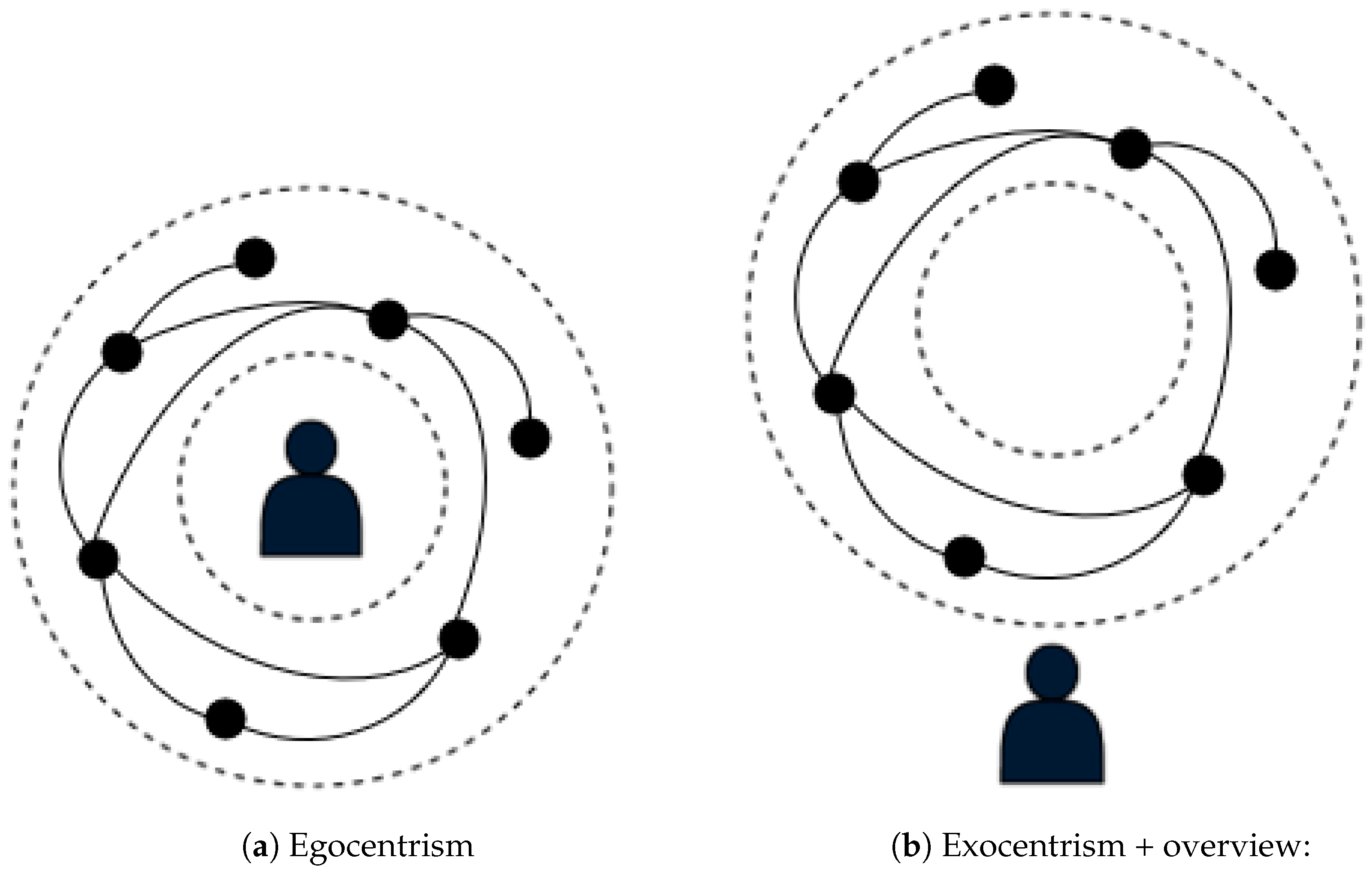
Thus, in order to improve spatialization and avoid a user getting entangled in nodes and edges, we create an empty area in its close surroundings. This empty area is a sphere with a minimum radius  r i n t  of 2.5 m so that the sphere completely envelops the user in immersion. Note that the user has the possibility to leave this zone (see Figure 5b). We then position the nodes (result of a 3D spatialization algorithm) between the user’s zone and another sphere of radius  r e x t > r i n t . The minimum value of  r e x t  is by default equal to  2 × r i n t , and its maximum value depends on the number of nodes in the graph. The maximum value of  r i n t  is defined as a function of the current value of  r e x t . Equation (1) illustrates how we compute the position of a node i between the spheres:
P i = d i · P i | | P i | |
where:
P i  is the position of node i using a 3D spatialization algorithm;
P i  is the position of node i between the spheres;
d i = r i n t + | | P i | | d m a x · ( r e x t r i n t )  is the new distance between a node i and the center, and  d m a x  is the distance between a most distant node and the center.
To improve the edge drawing, we do not let any edge cross the empty space of the user (the inner sphere). To achieve this, we push the edges into the area delimited by our two concentric spheres (Figure 5a). We first segmented the edges into a number of points; we then applied the same principle as for the nodes to push them between the spheres. Thus, the user can move freely in their space without being encumbered by edges.
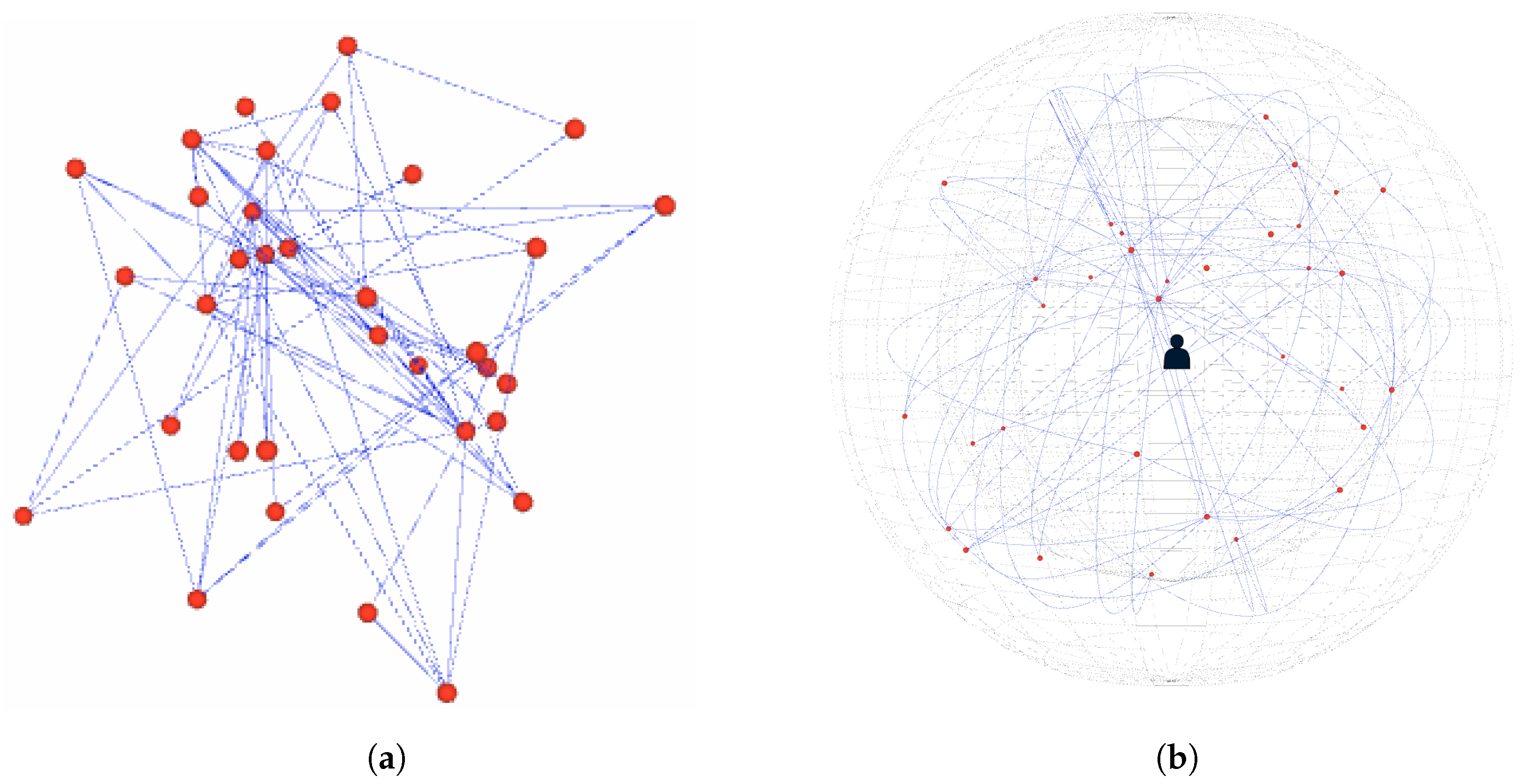
Figure 6a,b show a 3D visualization of the graph of the dataset “Karate Club” (34 nodes and 78 edges) with a spatialization of the nodes carried out, respectively, by Fruchterman and Reingold’s algorithm [1] and by our egocentric metaphor. The result in Figure 6b shows a good expansion of the nodes with our method compared with the result of Fruchterman and Reingold’s algorithm (Figure 6a).

3.2. Contraction of the Spherical Bubble Space

With the egocentric approaches of Sorger et al. [21], the user may lose the perception of some nodes and their connectivity. It is the same for a traditional immersive method. Having a detailed view alone cannot enable a user to identify interesting areas in a graph. Thus, it may be useful to combine an overview of a graph with an egocentric view to allow an analyst to switch from one view to the other. However, this introduces several new challenges about how to display nodes that are behind a user or outside their field of view.
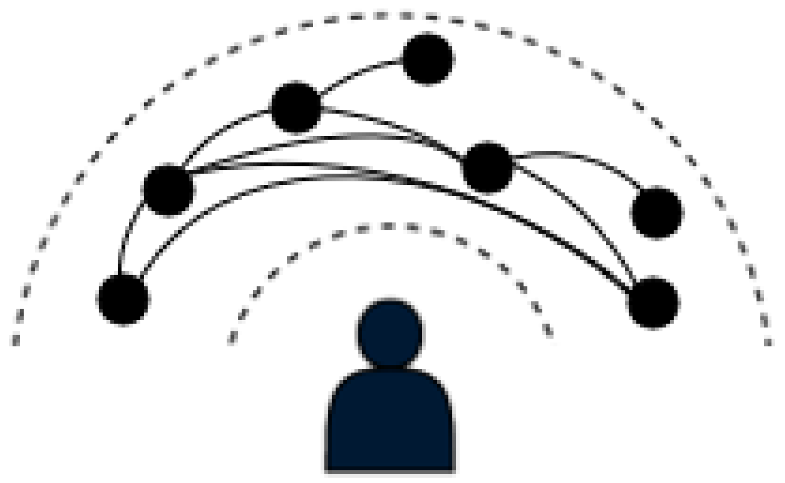
This is why we propose a possibility to retract the graph display space along the vertical and horizontal axes (see Figure 7) while remaining egocentric. It can be considered as a kind of flexible extension of the 360° cylindrical view proposed by the Pano through-the-lens technique [25], based on a dynamic spherical reduction in the space rather than on a predetermined portion of cylinder.
The retraction of the graph display space is related to the orientation of the camera. So, we first retrieve the direction (forward vector) in which the user (camera) is looking. We then retrieve the right vector of the camera’s view. The right vector corresponds to the x-axis in world space. We finally take the cross-product of the forward and right vectors. This cross-product gives us the vector pointing upwards relative to the camera’s orientation.
Below, we describe the various steps that are relevant to our proposed method of projecting the position of the nodes onto the retracted surface. As previously mentioned, the projection is influenced by two planes along the vertical and horizontal axes. The projection of a vector  u  onto a plane can be calculated as follows:
P r o j P l a n e ( u ) = u u · n | | n | | 2 · n
where  n  is the plane normal vector.
  • Projection onto the first plane defined by the vertical axis:
    • We first project the direction of the camera onto the plane. According to the Equation (2),  u  corresponds to the forward vector of the camera and  n  corresponds to the vector pointing upwards relative to the camera’s orientation.
    • We then find the initial position’s projection within the plane. In the above Equation (2),  u  corresponds to  P i , the initial position of the node i and  n  is the upwards vector relative to the camera’s orientation.
    • We calculate the signed angle between the projected direction and the projected initial position around the vertical axis. We then scale it based on the current horizontal axis slider value (see Equation (3)).
      θ y = θ y · h 180
      where  θ y = a c o s ( D c · P i y | | D c | | · | | P i y | | )  is the signed angle between the projected direction  D c  and the projected initial position  P i y  of the node i, and  h ( 0 h 180 )  is the current value of the horizontal axis slider.
    • We then update the projected initial position by applying the calculated angle-based rotations to it (see Equation (4)).
      P i y = R θ y · R θ y · P i
      where  R θ y  and  R θ y  are, respectively, the rotation by  θ y  and  θ y  about  y -axis.
    • We finally normalize the projected initial position to lie on the retracted surface (see Equation (5)). Let  P i  be the normalized position.
      P i = | | P i | | · P i y | | P i y | |
  • Projection onto the second plane defined by the horizontal axis:
    • We project the normalized position from the Equation (5) onto the second plane defined by the right vector of the camera’s view. As previously mentioned, the right vector corresponds to the  x -axis in world space. Let  P i x  be the result of the projected position. In the Equation (2),  u  corresponds to  P i  and  n  corresponds to the right vector of the camera’s view.
    • We then calculate the signed angle between the projected direction (at item 1) and  P i x  around the horizontal axis. We scale it based on the current vertical axis slider value (see Equation (6)).
      θ x = θ x · v 180
      where  θ x = a c o s ( D c · P i x | | D c | | · | | P i x | | )  is the signed angle between the projected direction  D c  and  P i x  (see Equation (5)), and  v ( 0 v 180 )  is the current value of the vertical axis slider.
    • We update the final projected position by applying the determined angle-based rotations to it (see Equation (7)) and finally normalize it to lie on the retracted surface (see Equation (8)). Let  P i x  be the result of the applied rotations, and  P i  be the final position of the node i on the retracted surface.
      P i x = R θ x · R θ x · P i
      where  R θ x  and  R θ x  are, respectively, the rotation by  θ x  and  θ x  about  x -axis.
      P i = | | P i | | · P i x | | P i x | |
Using a slider to control the horizontal axis and a slider to control the vertical axis, an analyst can retract the display space of a graph horizontally and/or vertically to be able to obtain an overall view of the graph without changing its structure. This can also be performed using many other interaction methods. This type of egocentric graph visualization provides perceptual advantages that allow an analyst to understand the graph structure more quickly than with an exocentric visualization.
Figure 8 illustrates some inside view aspects of the retraction of the display space of the karate club graph.

3.3. Discussion

Visual clutter is still a crucial problem of some graph visualization techniques, and therefore, many improvements on graph visualization continue to be presented [26], such as immersive techniques.
However, some work has shown that virtual environments have drawbacks, such as cybersickness [27,28]. But evaluation results of the egocentric metaphor proposed by Sorger et al. [21] suggest that egocentricity has the potential to overcome some of the inherent drawbacks of virtual environments (e.g., visual clutter and cybersickness).
In our egocentric approach, the user becomes the center of attention within a 3D space enclosed by spheres. Therefore, placing the user at the center of a sphere makes it possible for them to have a user-centric view of the graph. This means that the user is not merely an observer but an active participant in the exploration of the graph.
Our egocentric approach therefore helps improve graph exploration, since the user has free space around them. Placing the user inside a sphere creates an engaging experience that leads to a deeper understanding of the graph’s structure. Shrinking the edges between the area delimited by our two concentric spheres also improves the visibility of connectivity between graph nodes. The user therefore gains a better sense of spatial relationships between nodes. Our retractable space approach makes it possible for an analyst to switch between a detailed and an overview view of the graph. This approach is useful for identifying dense areas of the graph in global mode and then understanding the connectivity between nodes in a given area. Moreover, navigating within the spheres can be more intuitive than traditional 2D graph visualizations, as the user can move their head or body to explore different parts of the graph.
However, switching from a detailed view to an overview by shrinking the graph display space can lead to edge occlusions. An edge grouping algorithm can then be an alternative to reduce this visual clutter and improve the readability of the graph.

4. Conclusions

Our egocentric graph visualization metaphor makes it possible to improve the visibility of nodes’ connectivity in a graph, as it places the user inside the graph in a safe bubble without any nodes or any edges. It also enables the user to have a global view of the graph by retracing the graph display space along the vertical and horizontal axes. Overall, our egocentric method has the potential to provide deeper insights and enhance the understanding of graphs, particularly for complex network structures.
However, we have not conducted any experimentation yet to compare our proposal with other existing approaches in terms of performance. In addition, its effectiveness may vary depending on the user’s familiarity with immersive technologies. Nevertheless, as the evaluation results of the egocentric approach proposed by Sorger et al. show that an egocentric visualization and an adapted interaction design can bring significant advantages in immersive graph exploration, our Spherical Retractable Bubble Space can be an improvement for graph exploration.
In the future, we can also make it possible to move the inner personal sphere of the user inside the global sphere to obtain yet more different points of view on the global graph visualization, and as our users will have to cope with a limited physical space for their movements. We will first consider that this inner sphere is similar to the stage of the IIVC model [29] in order to convey this stage in the virtual immersive environment dedicated to the whole graph visualization. This will be performed by coupling our Spherical Retractable Bubble Space Metaphor with other VR navigation metaphors, such as the “Bubble” technique [30] or the “Magic Barrier Tape” technique [31], which are both navigation techniques dedicated to navigation within limited physical workspaces.

Author Contributions

P.K. is the main contributor of the software development of the system, he contributed also to the design of the system. T.D. and L.B. proposed the concept of retractable space and contributed to the design of the system. All authors have read and agreed to the published version of the manuscript.

Funding

This work has been funded by a grant from Brittany region, France, and this work was also supported by French government funding managed by the National Research Agency under the Investments for the Future program (PIA) grant ANR-21-ESRE-0030 (CONTINUUM). We also gratefully acknowledge the support of the NVIDIA Corporation with the donation of the Titan Xp GPU used for this research.

Data Availability Statement

To validate our system we used the Karate Club dataset available at http://vlado.fmf.uni-lj.si/pub/networks/data/Ucinet/UciData.htm#zachary [24].

Acknowledgments

We want to thank Raphaël Caby and Thalie Borderon who contributed to a preliminary implementation of the system during their undergraduate internship.

Conflicts of Interest

The authors declare no conflict of interest. The funders had no role in the design of the system, nor in the writing of the paper, nor in the decision to publish the results.

References

  1. Fruchterman, T.M.J.; Reingold, E.M. Graph drawing by force-directed placement. Software Pract. Exp. 1991, 21, 1129–1164. [Google Scholar] [CrossRef]
  2. Kamada, T.; Kawai, S. An algorithm for drawing general undirected graphs. Inf. Process. Lett. 1989, 31, 7–15. [Google Scholar] [CrossRef]
  3. Walshaw, C. A Multilevel Algorithm for Force-Directed Graph Drawing. J. Graph Algorithms Appl. 2003, 7, 253–285. [Google Scholar] [CrossRef]
  4. Jacomy, M.; Venturini, T.; Heymann, S.; Bastian, M. ForceAtlas2, a Continuous Graph Layout Algorithm for Handy Network Visualization Designed for the Gephi Software. PLoS ONE 2014, 9, e98679. [Google Scholar] [CrossRef] [PubMed]
  5. Hachul, S.; Jünger, M. Large-Graph Layout with The Fast Multipole Multilevel Method; Universität zu Köln: Cologne, Germany, 2005. [Google Scholar]
  6. Zellmann, S.; Weier, M.; Wald, I. Accelerating Force-Directed Graph Drawing with RT Cores. In Proceedings of the 2020 IEEE Visualization Conference (VIS), Salt Lake City, UT, USA, 25–30 October 2020; pp. 96–100. [Google Scholar] [CrossRef]
  7. Brandes, U.; Pich, C. An experimental study on distance-based graph drawing. In Proceedings of the Graph Drawing; Number 5417 in Lecture Notes in Computer Science; Tollis, I.G., Patrignani, M., Eds.; Springer: Berlin/Heidelberg, Germany, 2009; pp. 218–229. [Google Scholar] [CrossRef]
  8. Brandes, U.; Pich, C. Eigensolver Methods for Progressive Multidimensional Scaling of Large Data. In Proceedings of the Graph Drawing, 14th International Symposium, GD 2006, Karlsruhe, Germany, 18–20 September 2006; Revised Papers, Lecture Notes in Computer Science; Kaufmann, M., Wagner, D., Eds.; Springer: Berlin/Heidelberg, Germany, 2006; Volume 4372, pp. 42–53. [Google Scholar] [CrossRef]
  9. Erdos, P.; Pach, J.; Pollack, R.; Tuza, Z. Radius, diameter, and minimum degree. J. Comb. Theory Ser. B 1989, 47, 73–79. [Google Scholar] [CrossRef]
  10. Ersoy, O.; Hurter, C.; Paulovich, F.; Cantareiro, G.; Telea, A. Skeleton-Based Edge Bundling for Graph Visualization. IEEE Trans. Vis. Comput. Graph. 2011, 17, 2364–2373. [Google Scholar] [CrossRef] [PubMed]
  11. Hurter, C.; Ersoy, O.; Telea, A. Graph Bundling by Kernel Density Estimation. Comput. Graph. Forum 2012, 31, 865–874. [Google Scholar] [CrossRef]
  12. Ware, C.; Mitchell, P. Visualizing OctGraphs in Three Dimensions. ACM Trans. Appl. Percept. 2008, 5, 1279642. [Google Scholar] [CrossRef]
  13. Lu, J.; Si, Y.W. Clustering-based force-directed algorithms for 3D graph visualization. J. Supercomput. 2020, 76, 1–62. [Google Scholar] [CrossRef]
  14. Zacks, J.; Levy, E.; Tversky, B.; Schiano, D. Reading Bar Graphs: Effects of Extraneous Depth Cues and Graphical Context. J. Exp. Psychol. Appl. 1998, 4, 119–138. [Google Scholar] [CrossRef]
  15. Greffard, N.; Picarougne, F.; Kuntz, P. Beyond the classical monoscopic 3D in graph analytics: An experimental study of the impact of stereoscopy. In Proceedings of the 2014 IEEE VIS International Workshop on 3DVis (3DVis), Paris, France, 9 November 2014; pp. 19–24. [Google Scholar] [CrossRef]
  16. Cliquet, G.; Perreira, M.; Picarougne, F.; Prié, Y.; Vigier, T. Towards HMD-based Immersive Analytics. In Proceedings of the Immersive Analytics Workshop of IEEE VIS 2017, Phoenix, AZ, USA, 1 October 2017. [Google Scholar]
  17. Kwon, O.H.; Muelder, C.; Lee, K.; Ma, K.L. Spherical layout and rendering methods for immersive graph visualization. In Proceedings of the 2015 IEEE Pacific Visualization Symposium (PacificVis), Hangzhou, China, 14–17 April 2015; pp. 63–67. [Google Scholar] [CrossRef]
  18. Kwon, O.H.; Muelder, C.; Lee, K.; Ma, K.L. A Study of Layout, Rendering, and Interaction Methods for Immersive Graph Visualization. IEEE Trans. Vis. Comput. Graph. 2016, 22, 1802–1815. [Google Scholar] [CrossRef] [PubMed]
  19. Brisson, L.; Duval, T.; Sahl, R. Visualisation Immersive de Graphes en 3D pour explorer des graphes de communautés. EGC-VIF 2018, 1, 01759070. [Google Scholar]
  20. Marriott, K.; Chen, J.; Hlawatsch, M.; Itoh, T.; Nacenta, M.A.; Reina, G.; Stuerzlinger, W. Immersive Analytics: Time to Reconsider the Value of 3D for Information Visualisation. In Immersive Analytics; Springer: Berlin/Heidelberg, Germany, 2018; pp. 25–55. [Google Scholar] [CrossRef]
  21. Sorger, J.; Arleo, A.; Kán, P.; Knecht, W.; Waldner, M. Egocentric Network Exploration for Immersive Analytics. Comput. Graph. Forum 2021, 40, 241–252. [Google Scholar] [CrossRef]
  22. Yang, Y.; Jenny, B.; Dwyer, T.; Marriott, K.; Chen, H.; Cordeil, M. Maps and Globes in Virtual Reality. Comput. Graph. Forum 2018, 37, 427–438. [Google Scholar] [CrossRef]
  23. Sadana, R.; Setlur, V.; Stasko, J. Redefining a Contribution for Immersive Visualization Research. In Proceedings of the 2016 ACM Companion on Interactive Surfaces and Spaces, Association for Computing Machinery, 2016, ISS’16 Companion, Niagara Falls, ON, Canada, 6–9 November; 2016; pp. 41–45. [Google Scholar] [CrossRef]
  24. Zachary, W.W. An Information Flow Model for Conflict and Fission in Small Groups. J. Anthropol. Res. 1977, 33, 452–473. [Google Scholar] [CrossRef]
  25. Clergeaud, D.; Guitton, P. Pano: Design and evaluation of a 360° through-the-lens technique. In Proceedings of the 2017 IEEE Symposium on 3D User Interfaces (3DUI), Los Angeles, CA, USA, 18–19 March 2017; pp. 2–11. [Google Scholar] [CrossRef]
  26. Sassa, H.; Itoh, T.; Yoshida, M. 3D Visualization of Network Including Nodes with Labels. In Proceedings of the 23rd International Conference Information Visualisation (IV), Paris, France, 2–5 July 2019; pp. 19–24. [Google Scholar] [CrossRef]
  27. So, R.H.Y.; Ho, A.; Lo, W.T. A Metric to Quantify Virtual Scene Movement for the Study of Cybersickness: Definition, Implementation, and Verification. Presence Teleoperators Virtual Environ. 2001, 10, 193–215. [Google Scholar] [CrossRef]
  28. So, R.H.Y.; Lo, W.T.; Ho, A.T.K. Effects of Navigation Speed on Motion Sickness Caused by an Immersive Virtual Environment. Hum. Factors 2001, 43, 452–461. [Google Scholar] [CrossRef] [PubMed]
  29. Fleury, C.; Chauffaut, A.; Duval, T.; Gouranton, V.; Arnaldi, B. A Generic Model for Embedding Users’ Physical Workspaces into Multi-Scale Collaborative Virtual Environments. In Proceedings of the ICAT 2010 20th International Conference on Artificial Reality and Telexistence, Adelaide, Australia, 1–3 December 2010. [Google Scholar]
  30. Dominjon, L.; Lecuyer, A.; Burkhardt, J.M.; Andrade-Barroso, G.; Richir, S. The “Bubble” technique: Interacting with large virtual environments using haptic devices with limited workspace. In Proceedings of the First Joint Eurohaptics Conference and Symposium on Haptic Interfaces for Virtual Environment and Teleoperator Systems. World Haptics Conference, Pisa, Italy, 18–20 March 2005; pp. 639–640. [Google Scholar] [CrossRef]
  31. Cirio, G.; Marchal, M.; Regia-Corte, T.; Lécuyer, A. The Magic Barrier Tape: A Novel Metaphor for Infinite Navigation in Virtual Worlds with a Restricted Walking Workspace. In Proceedings of the 16th ACM Symposium on Virtual Reality Software and Technology; Association for Computing Machinery, New York, NY, USA, 18–20 November 2009; pp. 155–162. [Google Scholar] [CrossRef]
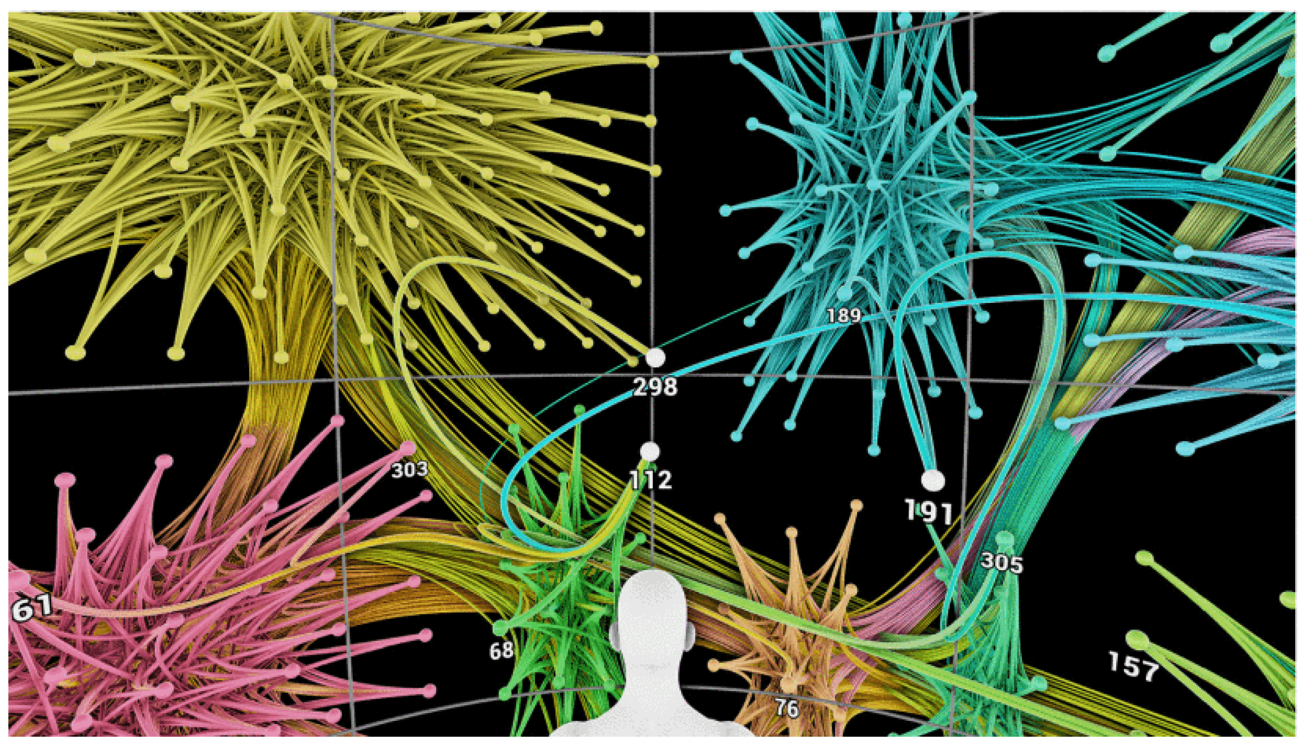
Figure 1. Spherical visualizations of graphs (image is from Kwon et al. [18], © 2016, IEEE).
Information 14 00531 g001
Figure 2. Spherical graph visualizations (image is from Kwon et al. [17], © 2015, IEEE). When a user selects a node, this node and its neighboring nodes are brought closer to the user.
Information 14 00531 g002
Figure 3. In this 2D visualization, the entire graph may be visible, but it is difficult to discern the connectivity of certain nodes. In the immersive environment, only a small section of the graph is visible at any given time, but the structure is more tangible (image is from Kwon et al. [17], © 2015, IEEE).
Information 14 00531 g003
Figure 4. Immersive exploration of the node’s neighbors: (a) Classic: the user inspects the UI46 node up close. (b) Ego-highlight: the user takes the position of the UI46 node, with direct neighbors highlighted in yellow. (c) Ego-bubble: direct neighbors are positioned equidistant from the user. (Images taken from Sorger et al. [21]).
Information 14 00531 g004
Figure 5. (a) The user is placed at the center of the inner sphere and some edges are projected out. (b) Global view of the graph by moving out of the spheres, but some nodes will appear far from the user.
Information 14 00531 g005
Figure 6. Visualization of the karate club graph (34 nodes (red dots) and 78 edges (blue lines)) [24]: (a) visualization using Fruchterman and Reingold’s algorithm; (b) our egocentric metaphor where the graph is positioned between two concentric spheres.
Information 14 00531 g006
Figure 7. Overview: a user can retract the graph display space in order to have a global view while remaining egocentric.
Information 14 00531 g007
Figure 8. Retraction of the Spherical Bubble Space (from inside view of the user): V = angle along the vertical axis and H = angle along the horizontal axis. Red dots are the nodes of the graph and blue lines are the links between nodes.
Information 14 00531 g008
Disclaimer/Publisher’s Note: The statements, opinions and data contained in all publications are solely those of the individual author(s) and contributor(s) and not of MDPI and/or the editor(s). MDPI and/or the editor(s) disclaim responsibility for any injury to people or property resulting from any ideas, methods, instructions or products referred to in the content.