

Deep-Learning-Based Multitask Ultrasound Beamforming


Abstract
:1. Introduction
- Receiving echo of the generated ultrasonic wave;
- Applying time of flight correction to the received signal;
- Beamforming the time-aligned signal’s array;
- Applying log compression;
- Image post-processing.
2. Related Work
- Scalability: given enough task-specific data, one has to train only a small portion of their complete architecture—the fully connected AdaIN layer parameters;
- Performance: during inference, the AdaIN parameters can be pre-computed, and hence only a single forward pass of the U-Net network is required to generate task-specific output.
3. Existing Beamformers
3.1. Plane Wave Ultrasound Imaging
3.2. Ultrasound Image Formation Pipeline
4. Multi-Task Learning
4.1. Proposed Architecture
4.2. Task Adaptive Output
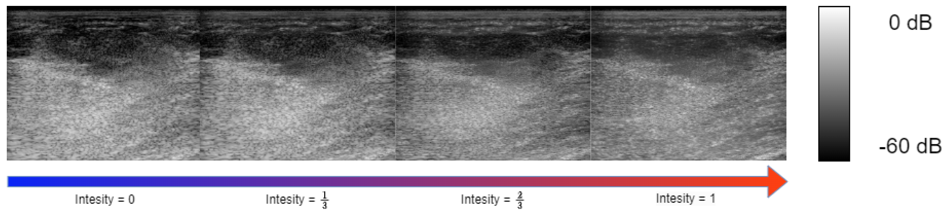
4.3. Controlling Task Intensity
5. Experimental Setup
5.1. Training and Evaluation Data
5.2. Target Samples Generation
- Base task: Multi-angle reconstruction from single-angle acquisition. The reconstruction of multi-angle acquisition from a single-angle acquisition yields a notable increase in performance. This is attributed to the faster sensor data acquisition from a single angle compared to a multi-angle acquisition setup. Furthermore, the beamforming algorithm benefits from increased efficiency as the dimensionality of the input signal is reduced. Both the multi-angle and single-acquisition samples are generated using DAS. For the single-angle acquisition samples, the target IQ tensor is beamformed with only a single center angle of 0°.
- Speckle noise denoising: In most commercial ultrasound devices, there is an image denoising algorithm as post-processing to the traditional beamforming after the conventional steps of envelope detection and log compression. Integrating the image-denoising step into the beamformer leads to further performance improvements. We generated our ground-truth samples for speckle noise reduction by applying [2], a variation of the Bayesian non-local-means image denoising algorithm, to the multi-angle DAS image formation pipeline output.
- Sub-sampled channel data reconstruction: Training the beamformer to reconstruct the IQ tensor from subsampled RF data in the channel axis introduces both performance and cost improvements, as it allows the usage of ultrasound probes with fewer transducer elements. Specifically, we applied a deterministic sub-sampling to our input IQ samples; we zeroed out all the transducer element recordings at even indexes, feeding our model with only sensor reading from odd transducer element indexes.
5.3. Evaluation Metrics
- Local image quality metrics: The challenge organizers chose a predefined region of interest (ROI) within the target images to evaluate local image quality. Those ROIs include lesions and point targets to evaluate denoising, contrast, and resolution. The final scoring of local image quality is a combination of the following metrics:where , , and represent the mean, standard deviation, and the histogram of ROI i. Additionally, full width at half maximum (FWHM) was calculated to measure the resolution of point targets.
- Global image quality metrics: Global image quality metrics are used to evaluate the global beamformed image quality compared to ground-truth in terms of and losses, peak signal-to-noise ratio (PSNR) and normalized cross-correlation ().where x is the envelope of the beamformed reconstruction and y is the corresponding ground-truth envelope.
5.4. Training Strategy
- Base task: First, we train the neural network for our base task; we used AdamW optimizer [36], with a learning rate of , and . The network is trained for 50 epochs with a step learning rate scheduler reducing the learning rate by a factor of 0.8 every 10 epochs. The batch size was set to 32. Each time-of-flight corrected RF acquisition sample is split into square patches with a width and height of 16 pixels, resulting in a total of 52,889 training samples and 13,070 validation samples. To further increase the data variety, custom data augmentations are used:
- (a)
- Row flipping: both the output and input IQ patch rows are flipped (mirrored);
- (b)
- Column flipping: both the output and input IQ patch columns are flipped (mirrored).
Each augmentation has been applied randomly with a probability of 30%. - Sub-tasks: After training for the base task, we chose the best-performing weights on the validation set, and then we trained only the convolution scale and bias parameters on each sub-task. The learning rate was set to , and , and the network convolution normalization parameters were trained for 20 epochs for each task. All the model training and experiment code was performed with the Pytorch [37] framework.
6. Results
6.1. Image Targets
6.2. Multi-Task Results
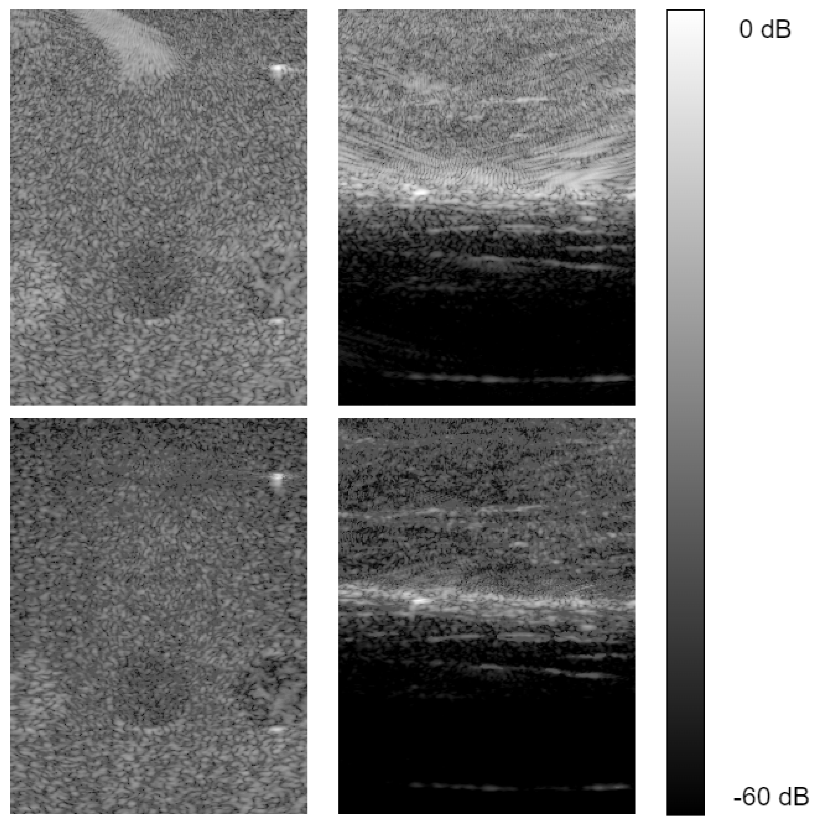
- Sub-sampling: We sub-sampled the input IQ cube at the channel dimension at a rate of , leaving only the elements at odd indexes. All other elements were removed (input data set to 0). We used the same test as in Section 5.4 and Section 6.1, evaluating local and global image quality compared to sub-sampled single-angle DAS. From Table 3, we notice our sub-sampled reconstruction model generates competitive global image target results relative to [14]. Also, our model suppresses the performance of single-angle sub-sampled reconstruction by a significant margin. Examining the local image quality evaluation scores in Table 2, our model still performs better than sub-sampled single-angle DAS reconstruction; however, it suffers from low contrast compared to other fully sampled reconstructions.
- Speckle noise reduction: To evaluate speckle noise reduction, we tested both global and local image quality metrics as described in (8)–(15). Our neural network speckle reduced image is compared against the speckle denoising algorithm in [2] applied to multi-angle (ground-truth) and single-angle reconstruction. Inspecting the local image quality metrics, from our results reported in Table 4, we see our model out-performs the speckle reduced single-angle DAS in every measurement except for contrast. The global image quality test results in Table 5 indicate our model outperforms the speckle denoised single-angle DAS generated image regarding global image quality metrics by a significant amount. In comparison to the ground-truth multi-angle DAS with speckle reduction, our reconstruction show an inferior contrast; however, it remains on par or better in other matrices, specifically gCNR and SpeckleSNR.
7. Discussion
8. Conclusions
Author Contributions
Funding
Data Availability Statement
Conflicts of Interest
Abbreviations
| DAS | Delay and sum |
| MVDR | Minimum variance distortionless response |
| CNN | Convolutional neural network |
| IQ | In-phase, Quadrature |
References
- Karthikeyan, S.; Manikandan, T.; Nandalal, V.; Mazher Iqbal, J.; Babu, J.J. A Survey on Despeckling Filters for Speckle Noise Removal in Ultrasound Images. In Proceedings of the 2019 3rd International conference on Electronics, Communication and Aerospace Technology (ICECA), Coimbatore, India, 12–14 June 2019; pp. 605–609. [Google Scholar] [CrossRef]
- Coupe, P.; Hellier, P.; Kervrann, C.; Barillot, C. Nonlocal means-based speckle filtering for ultrasound images. IEEE Trans. Image Process. 2009, 18, 2221–2229. [Google Scholar] [CrossRef] [PubMed]
- Sagheer, S.V.M.; George, S.N. Denoising of medical ultrasound images based on non-local similarity: A low-rank approach. In Proceedings of the TENCON 2017—2017 IEEE Region 10 Conference, Penang, Malaysia, 5–8 November 2017; pp. 176–181. [Google Scholar] [CrossRef]
- Lan, Y.; Zhang, X. Real-Time Ultrasound Image Despeckling Using Mixed-Attention Mechanism Based Residual UNet. IEEE Access 2020, 8, 195327–195340. [Google Scholar] [CrossRef]
- Dietrichson, F.; Smistad, E.; Ostvik, A.; Lovstakken, L. Ultrasound Speckle Reduction Using Generative Adversial Networks. In Proceedings of the 2018 IEEE International Ultrasonics Symposium, (IUS), Kobe, Japan, 22–25 October 2018; pp. 1–4. [Google Scholar] [CrossRef]
- Khor, H.G.; Ning, G.; Zhang, X.; Liao, H. Ultrasound Speckle Reduction Using Wavelet-Based Generative Adversarial Network. IEEE J. Biomed. Health Inform. 2022, 26, 3080–3091. [Google Scholar] [CrossRef] [PubMed]
- Lee, H.; Lee, M.H.; Youn, S.; Lee, K.; Lew, H.M.; Hwang, J.Y. Speckle Reduction via Deep Content-Aware Image Prior for Precise Breast Tumor Segmentation in an Ultrasound Image. IEEE Trans. Ultrason. Ferroelectr. Freq. Control 2022, 69, 2638–2650. [Google Scholar] [CrossRef]
- Mozaffarzadeh, M.; Mahloojifar, A.; Periyasamy, V.; Pramanik, M.; Orooji, M. Eigenspace-Based Minimum Variance Combined With Delay Multiply and Sum Beamformer: Application to Linear-Array Photoacoustic Imaging. IEEE J. Sel. Top. Quantum Electron. 2019, 25, 1–8. [Google Scholar] [CrossRef]
- Alzubaidi, L.; Bai, J.; Al-Sabaawi, A.; Santamaría, J.; Albahri, A.S.; Al-dabbagh, B.S.N.; Fadhel, M.A.; Manoufali, M.; Zhang, J.; Al-Timemy, A.H.; et al. A survey on deep learning tools dealing with data scarcity: Definitions, challenges, solutions, tips, and applications. J. Big Data 2023, 10, 46. [Google Scholar] [CrossRef]
- Alammar, Z.; Alzubaidi, L.; Zhang, J.; Li, Y.; Lafta, W.; Gu, Y. Deep Transfer Learning with Enhanced Feature Fusion for Detection of Abnormalities in X-ray Images. Cancers 2023, 15, 4007. [Google Scholar] [CrossRef] [PubMed]
- Chen, C.; Zhou, K.; Wang, Z.; Xiao, R. Generative Consistency for Semi-Supervised Cerebrovascular Segmentation From TOF-MRA. IEEE Trans. Med. Imaging 2023, 42, 346–353. [Google Scholar] [CrossRef] [PubMed]
- SORENSON, T. A method of establishing groups of equal amplitude in plant sociology based on similarity of species content, and its application to analysis of vegetation on Danish commons. Kong Dan Vidensk. Selsk. Biol. Skr. 1948, 5, 1–5. [Google Scholar]
- Luijten, B.; Cohen, R.; de Bruijn, F.J.; Schmeitz, H.A.W.; Mischi, M.; Eldar, Y.C.; van Sloun, R.J.G. Adaptive Ultrasound Beamforming Using Deep Learning. IEEE Trans. Med. Imaging 2020, 39, 3967–3978. [Google Scholar] [CrossRef] [PubMed]
- Goudarzi, S.; Asif, A.; Rivaz, H. Ultrasound Beamforming using MobileNetV2. In Proceedings of the 2020 IEEE International Ultrasonics Symposium (IUS), Las Vegas, NV, USA, 7–11 September 2020; pp. 1–4. [Google Scholar] [CrossRef]
- Sandler, M.; Howard, A.; Zhu, M.; Zhmoginov, A.; Chen, L.C. MobileNetV2: Inverted Residuals and Linear Bottlenecks. In Proceedings of the 2018 IEEE/CVF Conference on Computer Vision and Pattern Recognition, Salt Lake City, UT, USA, 18–23 June 2018; pp. 4510–4520. [Google Scholar] [CrossRef]
- Rothlübbers, S.; Strohm, H.; Eickel, K.; Jenne, J.; Kuhlen, V.; Sinden, D.; Günther, M. Improving Image Quality of Single Plane Wave Ultrasound via Deep Learning Based Channel Compounding. In Proceedings of the 2020 IEEE International Ultrasonics Symposium (IUS), Las Vegas, NV, USA, 7–11 September 2020; pp. 1–4. [Google Scholar] [CrossRef]
- Liebgott, H.; Rodriguez-Molares, A.; Cervenansky, F.; Jensen, J.; Bernard, O. Plane-Wave Imaging Challenge in Medical Ultrasound. In Proceedings of the 2016 IEEE International Ultrasonics Symposium (IUS), Tours, France, 18–21 September 2016; pp. 1–4. [Google Scholar] [CrossRef]
- Wang, Z.; Simoncelli, E.; Bovik, A. Multiscale structural similarity for image quality assessment. In Proceedings of the Thrity-Seventh Asilomar Conference on Signals, Systems & Computers, Pacific Grove, CA, USA, 9–12 November 2003; Volume 2, pp. 1398–1402. [Google Scholar] [CrossRef]
- Bhatt, M.; Nair, A.A.; Kempski, K.M.; Lediju Bell, M.A. Multi-task learning for ultrasound image formation and segmentation directly from raw in vivo data. In Proceedings of the 2020 IEEE International Ultrasonics Symposium (IUS), Las Vegas, NV, USA, 7–11 September 2020; pp. 1–4. [Google Scholar] [CrossRef]
- Ronneberger, O.; Fischer, P.; Brox, T. U-Net: Convolutional Networks for Biomedical Image Segmentation. In Proceedings of the Medical Image Computing and Computer-Assisted Intervention—MICCAI 2015; Navab, N., Hornegger, J., Wells, W.M., Frangi, A.F., Eds.; Springer International Publishing: Cham, Switzerland, 2015; pp. 234–241. [Google Scholar]
- Khan, S.; Huh, J.; Ye, J.C. Switchable Deep Beamformer For Ultrasound Imaging Using Adain. In Proceedings of the 2021 IEEE 18th International Symposium on Biomedical Imaging (ISBI), Nice, France, 13–16 April 2021; pp. 677–680. [Google Scholar] [CrossRef]
- Huang, X.; Belongie, S. Arbitrary Style Transfer in Real-time with Adaptive Instance Normalization. In Proceedings of the IEEE International Conference on Computer Vision (ICCV), Venice, Italy, 22–29 October 2017. [Google Scholar]
- Bell, M.A.L.; Huang, J.; Hyun, D.; Eldar, Y.C.; van Sloun, R.; Mischi, M. Challenge on Ultrasound Beamforming with Deep Learning (CUBDL). In Proceedings of the 2020 IEEE International Ultrasonics Symposium (IUS), Las Vegas, NV, USA, 7–11 September 2020; pp. 1–5. [Google Scholar] [CrossRef]
- Capon, J. High-resolution frequency-wavenumber spectrum analysis. Proc. IEEE 1969, 57, 1408–1418. [Google Scholar] [CrossRef]
- Mehdizadeh, S.; Austeng, A.; Johansen, T.F.; Holm, S. Eigenspace Based Minimum Variance Beamforming Applied to Ultrasound Imaging of Acoustically Hard Tissues. IEEE Trans. Med. Imaging 2012, 31, 1912–1921. [Google Scholar] [CrossRef] [PubMed]
- Matrone, G.; Savoia, A.S.; Caliano, G.; Magenes, G. The Delay Multiply and Sum Beamforming Algorithm in Ultrasound B-Mode Medical Imaging. IEEE Trans. Med. Imaging 2015, 34, 940–949. [Google Scholar] [CrossRef] [PubMed]
- Matrone, G.; Ramalli, A.; Savoia, A.S.; Tortoli, P.; Magenes, G. Improved resolution and crosstalk rejection in Multi-Line Transmit ultrasound imaging using Delay Multiply and Sum beamforming. In Proceedings of the 2016 IEEE International Ultrasonics Symposium (IUS), Tours, France, 18–21 September 2016; pp. 1–4. [Google Scholar] [CrossRef]
- Hendrycks, D.; Gimpel, K. Gaussian Error Linear Units (GELUs). arXiv 2020, arXiv:1606.08415. [Google Scholar]
- Hyun, D.; Wiacek, A.; Goudarzi, S.; Rothlübbers, S.; Asif, A.; Eickel, K.; Eldar, Y.C.; Huang, J.; Mischi, M.; Rivaz, H.; et al. Deep Learning for Ultrasound Image Formation: CUBDL Evaluation Framework and Open Datasets. IEEE Trans. Ultrason. Ferroelectr. Freq. Control 2021, 68, 3466–3483. [Google Scholar] [CrossRef] [PubMed]
- Wiacek, A.; Rindal, O.M.H.; Falomo, E.; Myers, K.; Fabrega-Foster, K.; Harvey, S.; Lediju Bell, M.A. Robust Short-Lag Spatial Coherence Imaging of Breast Ultrasound Data: Initial Clinical Results. IEEE Trans. Ultrason. Ferroelectr. Freq. Control 2019, 66, 527–540. [Google Scholar] [CrossRef] [PubMed]
- Li, Z.; Wiacek, A.; Bell, M.A.L. Beamforming with deep learning from single plane wave RF data. In Proceedings of the 2020 IEEE International Ultrasonics Symposium (IUS), Las Vegas, NV, USA, 7–11 September 2020; pp. 1–4. [Google Scholar] [CrossRef]
- Rindal, O.M.H.; Aakhus, S.; Holm, S.; Austeng, A. Hypothesis of Improved Visualization of Microstructures in the Interventricular Septum with Ultrasound and Adaptive Beamforming. Ultrasound Med. Biol. 2017, 43, 2494–2499. [Google Scholar] [CrossRef] [PubMed]
- Zhang, X.; Li, J.; He, Q.; Zhang, H.; Luo, J. High-Quality Reconstruction of Plane-Wave Imaging Using Generative Adversarial Network. In Proceedings of the 2018 IEEE International Ultrasonics Symposium (IUS), Kobe, Japan, 22–25 October 2018; pp. 1–4. [Google Scholar] [CrossRef]
- Rodriguez-Molares, A.; Rindal, O.M.H.; D’hooge, J.; Måsøy, S.E.; Austeng, A.; Lediju Bell, M.A.; Torp, H. The Generalized Contrast-to-Noise Ratio: A Formal Definition for Lesion Detectability. IEEE Trans. Ultrason. Ferroelectr. Freq. Control 2020, 67, 745–759. [Google Scholar] [CrossRef] [PubMed]
- Rindal, O.M.H.; Austeng, A.; Fatemi, A.; Rodriguez-Molares, A. The Effect of Dynamic Range Alterations in the Estimation of Contrast. IEEE Trans. Ultrason. Ferroelectr. Freq. Control 2019, 66, 1198–1208. [Google Scholar] [CrossRef] [PubMed]
- Loshchilov, I.; Hutter, F. Fixing Weight Decay Regularization in Adam. arXiv 2017, arXiv:1711.05101. [Google Scholar]
- Paszke, A.; Gross, S.; Chintala, S.; Chanan, G.; Yang, E.; DeVito, Z.; Lin, Z.; Desmaison, A.; Antiga, L.; Lerer, A. Automatic Differentiation in PyTorch. 2017. Available online: https://openreview.net/pdf?id=BJJsrmfCZ (accessed on 26 August 2023).


| Layer Type | Input Shape | Output Shape |
|---|---|---|
| ConvBlock | ||
| Max pooling | ||
| ConvBlock | ||
| max pooling | ||
| ConvBlock | ||
| max pooling | ||
| ConvBlock | ||
| ConvBlock | ||
| ConvBlock |
| Model | Contrast dB | Speckle CNR | gCNR | x Fwhm | z Fwhm | |
|---|---|---|---|---|---|---|
| Goudarzi et al. [14] | −13.77 | 1.345 | 0.814 | 1.827 | 0.0003 | 0.0004 |
| Single Plane | −10.5 | 1.05 | 0.674 | 1.85 | 0.0004 | 0.0004 |
| Ours | −15.84 | 1.632 | 0.88 | 2.299 | 0.0005 | 0.0003 |
| Ours— Sub Sampled | −5.07 | 1.083 | 0.62 | 1.94 | 0.0006 | 0.0003 |
| Single Plane— Sub Sampled | −4.95 | 0.542 | 0.394 | 1.842 | 0.0004 | 0.0004 |
| Ground-Truth—Multi-Plane | −24.70 | 1.53 | 0.946 | 1.806 | 0.0004 | 0.0003 |
| Model | PSNR | |||||
|---|---|---|---|---|---|---|
| Goudarzi et al. [14] | 0.03 | 0.42 | 0.05 | 0.56 | 29.10 | 0.91 |
| Single Plane | 0.03 | 0.39 | 0.042 | 0.53 | 30.36 | 0.93 |
| Ours | 0.029 | 0.36 | 0.0408 | 0.49 | 30.4 | 0.93 |
| Ours— Sub Sampled | 0.035 | 0.41 | 0.0504 | 0.55 | 28.52 | 0.9 |
| Single Plane— Sub Sampled | 0.0433 | 0.525 | 0.059 | 0.7 | 27.43 | 0.86 |
| Model | Contrast dB | Speckle CNR | gCNR | Speckle SNR |
|---|---|---|---|---|
| Single-Angle + speckle reduction | −10.5 | 1.05 | 0.674 | 1.85 |
| Ours: speckle reduction | −10.07 | 1.673 | 0.885 | 3.17 |
| Multi-Angle + speckle reduction (ground-truth) | −25.6 | 2.423 | 0.98 | 2.713 |
| Model | PSNR | |||
|---|---|---|---|---|
| Single Plane + speckle reduction | 0.57 | 1.07 | 24.8 | 0.593 |
| Ours-speckle reduction | 0.3 | 0.41 | 29.01 | 0.92 |
Disclaimer/Publisher’s Note: The statements, opinions and data contained in all publications are solely those of the individual author(s) and contributor(s) and not of MDPI and/or the editor(s). MDPI and/or the editor(s) disclaim responsibility for any injury to people or property resulting from any ideas, methods, instructions or products referred to in the content. |
© 2023 by the authors. Licensee MDPI, Basel, Switzerland. This article is an open access article distributed under the terms and conditions of the Creative Commons Attribution (CC BY) license (https://creativecommons.org/licenses/by/4.0/).
Share and Cite
Dahan, E.; Cohen, I. Deep-Learning-Based Multitask Ultrasound Beamforming. Information 2023, 14, 582. https://doi.org/10.3390/info14100582
Dahan E, Cohen I. Deep-Learning-Based Multitask Ultrasound Beamforming. Information. 2023; 14(10):582. https://doi.org/10.3390/info14100582
Chicago/Turabian StyleDahan, Elay, and Israel Cohen. 2023. "Deep-Learning-Based Multitask Ultrasound Beamforming" Information 14, no. 10: 582. https://doi.org/10.3390/info14100582
APA StyleDahan, E., & Cohen, I. (2023). Deep-Learning-Based Multitask Ultrasound Beamforming. Information, 14(10), 582. https://doi.org/10.3390/info14100582