Article

Multi-Beam STAR MIMO Using Differential Arrays

by
Yinyi Zhao
1,
Satheesh Bojja Venkatakrishnan
1,*,
Constantinos L. Zekios
1,
Soumyajit Mandal
2 and
Arjuna Madanayake
1,*
1
Department of Electrical and Computer Engineering, Florida International University, Miami, FL 33174, USA
2
Instrumentation Division, Brookhaven National Laboratory, Upton, NY 11973, USA
*
Authors to whom correspondence should be addressed.
Information 2025, 16(4), 321; https://doi.org/10.3390/info16040321
Submission received: 11 March 2025 / Revised: 13 April 2025 / Accepted: 14 April 2025 / Published: 18 April 2025
(This article belongs to the Special Issue Advances in Telecommunication Networks and Wireless Technology)

Abstract

:
As we are witnessing the surge of ongoing wireless communication systems, simultaneous transmit and receive (STAR) schemes are proving to be advantageous due to the doubling of spectral efficiency. However, for the successful realization of STAR, we need to overcome a major bottleneck in suppressing the self-interference from the transmitter onto the colocated receiver. Currently, mitigating this interference requires complex hardware and advanced algorithms when employing an array for applications such as multiple input, multiple output (MIMO), and beamforming. This interference can arise from both near-field and far-field coupling in a MIMO beamforming system. Consequently, this paper presents a unique STAR approach that provides an average isolation of 40 dB between Tx and Rx ports across all elements of the MIMO beamforming system. The proposed approach can be extended to large antenna arrays.

1. Introduction

Spectrum remains a precious commodity, with costs reaching billions of dollars for band licensing. The primary limitation of sub-6 GHz spectra is their overuse, leading to capacity constraints due to the high demand for wireless services [1,2]. Although smaller bandwidths were adequate in the past, the future of commercial and government applications requires much higher data rates, multiple beams, and increased transmit/receive gains. Furthermore, sub-6 GHz bands have historically enabled reliable communications but are susceptible to jamming signals [3,4,5]. Therefore, it is crucial to manage spectral resources effectively. In this paper, we expand and improve upon earlier works [6,7,8,9,10] to account for medium-range interference in the MIMO channel.
One approach to improving spectral efficiency is simultaneous transmit and receive (STAR) via in-band full-duplex (IBFD) communication [11]. This is quite different from existing time-duplexing (TD) or frequency duplexing (FD) approaches. In TD, we transmit and receive the signals using the same frequency band but at different time slots. On the other hand, FD transmits (uplink) and receives (downlink) at the same time but uses different frequency bands for uplink and downlink [12,13]. Both approaches use spectral and temporal resources suboptimally. STAR or IBFD can theoretically double the spectrum efficiency using the same frequency band at the same time slot [14]. The adoption of STAR, which has the IBFD property, allows new types of communication protocols, joint communication and sensing, and electronic warfare systems for dual-use [14,15,16,17,18,19].
Multiple input multiple output (MIMO) wireless systems are well known for achieving up to an N-fold increase in system capacity compared to single antenna radios. In fact, massive MIMO is the dominant technology for future wireless networks as it allows linear scaling with the number of independent channels in the MIMO-based radio frequency (RF) access system [20,21]. The ability to combine massive MIMO with IBFD-STAR communications can open up a lot of new possibilities for future wireless networks aimed at 6G/NextG deployments. For example, IBFD-STAR with MIMO can allow joint communication and sensing, increase capacity, and allow higher resilience to electromagnetic cyber-attacks as potential applications [18,22,23]. Figure 1 depicts an overview of the STAR MIMO scheme that utilizes beamformers, such as the Butler matrix, which is directly connected to the self-interference cancellation (SIC) network in the analog part of a multi-beam transceiver.
One major bottleneck associated with the successful realization of STAR is the coupling of high-power Tx signal onto collocated Rx antennas [24,25]. The leaked signals could be as high as 100 dB or more than the desired Rx signal. Consequently, we need to employ SIC approaches that can provide as high as 100 dB or more cancellation of the coupled signals [25]. This cancellation is achieved through multiple stages across antennas, RF stages, analog baseband, and digital stages [26,27,28,29,30,31,32,33].
However, the cancellation of self-interference in an antenna array becomes extremely challenging due to the increased number of elements. There are very limited studies on and instances of the realization of IBFD-STAR with MIMO arrays [10,34,35,36,37,38,39,40]. Most approaches suffer from either increased hardware demands or require complex algorithms to achieve self-interference cancellation [35,36,38,39,41,42]. In addition, the cancellation algorithms do not provide the desired SIC when the array scans.
To address the above shortfalls, in this article, we present a unique solution that employs a twin array that provides an average cancellation of 40 dB across the entire array antenna as shown in Figure 2. The proposed approach combines STAR with MIMO, and multi-beam beamforming with passive microwave circuits, for the first time in the literature. Section 4.1 will elaborate on the twin-array analytical model in Figure 2.
One further advantage of this approach is the fact that no additional hardware or reconfiguration is needed to maintain the desired SIC of 40 dB as the array antenna starts scanning (i.e., when beamforming) or when it is configured as a MIMO system. In other words, the proposed twin array approach guarantees the expected 40 dB SIC irrespective of the configuration of the antenna array.

2. Review of the Current MIMO Beamforming System

Current research on improving isolation in microstrip-based MIMO beamforming systems emulates two main approaches as follows: (i) integrating additional RF components into the system [43,44,45,46], and (ii) optimizing the design of antenna array structures [47,48,49,50,51].
The work in [47] presents a full-duplex 2 × 2 MIMO system that achieves an average isolation of 50 dB. In [48], the authors demonstrate a maximum isolation of 25 dB by using the concept of neutralization lines. In contrast, the authors in [43] apply analog adaptive filters to improve the total signal interference (SI) below −40 dB. Changes in antenna designs were explored in [49] to achieve an isolation of 34.6 dB on a dual-functional MIMO antenna array. The same group proposed an alternative MIMO system using slot antennas in [50], achieving a maximum isolation of 30 dB for their design. The authors in [44] proposed an in-band full-duplex (IBFD) beamformer utilizing a Butler matrix and a 4 × 4 MIMO array, achieving an average isolation of 38 dB for 5G communications. In [45], a coplanar waveguide (CPW)-fed ultra-wide bandwidth (UWB) MIMO system operating from 5 to 9 GHz was proposed based on the microstrip technology. A coplanar stripline (CPS)-fed UWB MIMO array system was proposed that achieves an average isolation of 25 dB for the 4 to 12 GHz frequency range [46]. An electromagnetic band gap (EBG) structure-based dual-layer dual-patch unit (DLDP-EBG) was used to improve the isolation for the MIMO system from 5 to 6.4 GHz, achieving an average isolation of 35 dB [51]. In [52], the authors applied the common mode and differential mode combined with microstrip couplers and combiners to achieve a 38 dB isolation from 3.3 to 3.8 GHz. To better improve the isolation performance, an active circuit was applied in work [53] to achieve another 20 dB isolation at 2.4 GHz based on the passive circuit.
Although the aforementioned works have made significant contributions to MIMO-STAR, they have the following drawbacks: (i) cancellation performance deteriorates as the array begins scanning, (ii) they are limited by narrow-band cancellation capabilities, and (iii) they require complex antenna array structure designs. Table 1 provides a comparison of the state-of-the-art MIMO beamforming system performances alongside our proposed system. Meanwhile, to better evaluate the trade-off between system isolation and bandwidth, we introduce a new normalized figure of merit (FOM), as follows:
M 1 = I B 100 F c
where I is the average isolation in linear scale, B is the bandwidth in GHz, and F c is the center frequency in GHz. For the consideration of easier comparison, M 1 is normalized by dividing it by 100.

3. Twin-Array SIC Solution

3.1. Twin-Array Approaches

The main challenge of the IBFD-STAR system for MIMO lies in the mutual coupling between all antennas within the MIMO wireless system. This includes both near-field coupling and far-field coupling through reflections in the environment. Typically, near-field electromagnetic coupling between antennas is significantly stronger than far-field coupling effects, perhaps by tens of dB. What that entails is that one has to mitigate the coupling effects in the near-field before addressing far-field coupling effects, as the near-field coupling is highly dominant. Furthermore, the near-field coupling causes strong near-field self-interference that is highly frequency-dependent and also depends on the geometry of the antenna. Circulator approaches do not always help with this issue, as the circulator-based STAR is fundamentally a single antenna approach [54]. There are a few high-isolation antenna approaches that can be employed for MIMO applications [55]. However, with these realizations, the SIC degrades as the arrays start scanning. In other words, the high SIC is valid only for specific operational modes or configurations.
Consequently, in this twin-array approach, we present an IBFD technique for MIMO arrays that provides a constant SIC independent of the operational modes. With this approach, we create an exact replica of the same Tx-Rx array to model the coupling between elements, even when scanning. Twin arrays are highly effective in canceling 30–40 dB of near-field coupling, which is dominant for MIMO-STAR. The problem is far-field coupling, which occurs when transmitted signals are scattered and reflected back to the receiver array, and it is highly influenced by the surrounding environment. Depending on obstructions, scattering, reflections, and other channel effects, the far-field self-interference is typically much smaller (30–60 dB lower) than near-field mutual coupling, and hence, it can be canceled out at subsequent stages.

3.2. Past Work on Twin Arrays

Past realizations of the twin-pair antenna canceler consider only a single Tx and single Rx [56]. This was later expanded to support multiple antennas, where the twin-array is placed inside a shielded RF chamber with absorbing walls [6]. Thereafter, the shielded RF chamber was replaced with an open array facing the rear of the main array [7]. In previous works, the twin-array SIC approaches were aimed towards the cancellation of near-field coupling across a wide band of operation across arrays with a large number of elements. In this new work, we propose a twin-array solution that not only cancels IBFD self-interference in the near-field but also allows for a significant reduction of far-field reflections by combining near-field cancellation with far-field beamforming within the twin-array architecture.

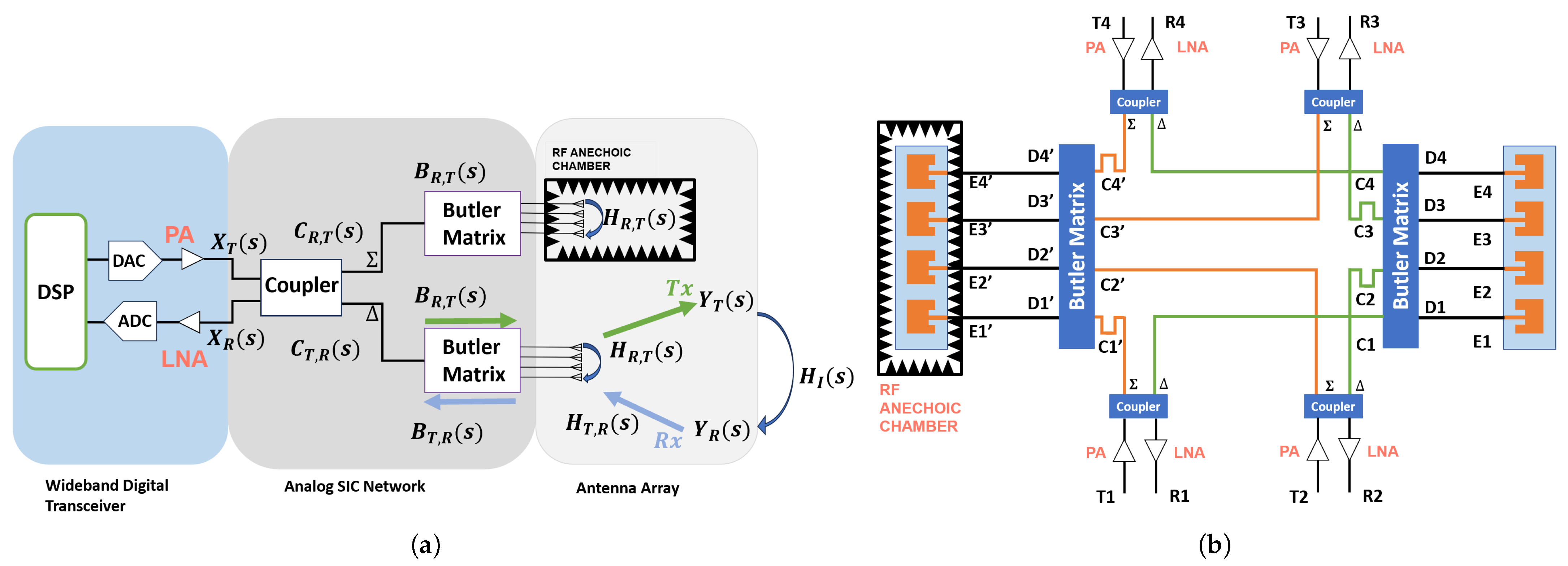
4. Proposed Twin Butler-Matrix Arrays

This section describes our proposed twin-array model for the STAR-MIMO beamformer. As shown in Figure 2, we combine a passive multi-beam beamformer matrix realized in passive microwave circuits with the twin-array concept.

4.1. Twin-Array Analytical Model

Let the transmit signal for N elements be represented by an N-point vector X T ( s ) and the forward beamforming matrix function of a Butler network for transmit signals is B R , T ( s ) , where port T = [ T 1 , T 2 , , T n ] T denotes the transmitting (Tx) port and port R = [ R 1 , R 2 , , R n ] T denotes the receiving (Rx) port. Following the power amplifier (PA), the forward (transmit) 180° coupler matrix function is C T , R ( s ) , and the reverse (receive) 180° coupler matrix function is C R , T ( s ) . Likewise, the reverse beamforming matrix function of a Butler matrix for received signals is B T , R ( s ) . The forward mutual coupling function of the aperture is H R , T ( s ) , and the reverse mutual coupling function of the aperture is H T , R ( s ) . The Butler matrix beamformer function for the Tx-mode, denoted as Y T ( s ) , can then be expressed as follows:
Y T ( s ) = H R , T ( s ) C R , T ( s ) B R , T ( s ) X T ( s )
where Y T ( s ) is the outgoing transmit signal across N-elements. For the Rx-mode, the incident received signal vector is denoted as Y R ( s ) . Next, we modify the above model to include self-interference.
In the presence of self-interference, the combined signal X R ( s ) at the receivers consists of the linear combination of the actual (desired) received signal plus the scattered and reflected component of the Tx signal, yielding the following:
X R ( s ) = H T , R ( s ) C T , R ( s ) B T , R ( s ) ( Y R ( s ) + Y T ( s ) )
The above expression is a combination of the near-field self-interference represented using Y T ( s ) and the desired received signal represented using Y R ( s ) .
Similarly, the received signals at the low-noise amplifier (LNA) input are the total combined scattering parameters including the Butler matrix and the aperture with mutual coupling effects, as seen by the incident Rx signals. Here we assume 50-ohm ports, allowing S-parameter matrices to be cascaded for modeling microwave systems without the need to apply multi-port ABCD parameter theory, which would otherwise complicate the mathematical model.
We combine the aperture coupling with Butler matrix beamforming to describe the total system using a single set of multi-port S-parameter functions. We note that the received signals Y R ( s ) consist of the following two components: (a) the desired far-field transmitter signal X S ( s ) , and (b) any external interference which includes reflected components of the transmitted signal, Y T ( s ) , due to environmental scattering. As shown in Figure 2, we can model the incident received signals as follows:
Y R ( s ) = X S ( s ) + H I ( s ) Y T ( s )
where X S ( s ) is the signal of interest, and H I ( s ) is the far-field self-interference channel matrix. H I ( s ) Y T ( s ) in (4) includes the far-field coupling interference of Y T ( s ) . The received signal at the LNA input, just from the actively receiving antenna arrays can then be represented as,
X R ( s ) = P T , R ( s ) Y R ( s ) + P T , R ( s ) Y T ( s )
where P T , R ( s ) = H T , R ( s ) C T , R ( s ) B T , R ( s ) .
Let the twin-array have corresponding S-parameter matrices P T , R ( s ) = P T , R ( s ) + Δ T , R ( s ) and P R , T ( s ) = P R , T ( s ) + Δ R , T ( s ) , where Δ T , R ( s ) and Δ R , T ( s ) are small-value error matrices which become null matrices for an electrically identical pair of arrays. Likewise, P R , T ( s ) = H R , T ( s ) C R , T ( s ) B R , T ( s ) . According to Figure 2, the received signal can be modeled by the following:
X R ( s ) = P T , R ( s ) Y R ( s ) + P T , R ( s ) Y T ( s ) P T , R ( s ) Y T ( s )
which implies that near-field self-interference perfectly cancels when Δ T , R ( s ) = 0 . Assuming for a moment that perfectly identical arrays are available, we are left with the received signal vector X R ( s ) = P T , R ( s ) [ X S ( s ) + H I ( s ) Y T ( s ) ] . In cases where the antenna arrays are not identical or the communication channel is significantly impacted by external conditions, such as extreme weather or a highly scattering environment, near-field self-interference may not be fully canceled. A brief discussion of these effects is provided in Section 4.2.
The received far-field self-interference from nearby scatterers is simply P T , R ( s ) H I ( s ) Y T ( s ) . The Butler matrix beamformer realizes discrete Fourier transform (DFT) like spatial beams. Therefore P T , R ( s ) imposes DFT receive beamforming, while P R , T ( s ) imposes DFT transmit beamforming on the Rx and Tx components. Far-field self-interference undergoes both transmit and receive beamforming, together with the scattering channel H I ( s ) . Therefore, unless H I ( s ) represents a retro-reflective surface that reflects the signal along the same direction of incidence, the received self-interference would be heavily attenuated due to the directional selectivity of the transmit and receive beams. On the other hand, the far-field received signal benefits from directional enhancement due to receive-mode DFT beamforming.
Thus, the only component at the input of the LNA after this process is P T , R ( s ) X S ( s ) . This leads to an improved signal-to-noise-and-interference ratio (SINR) through passive beamforming in the Butler matrix, as long as the correct beam port is selected for the specific far-field signal of interest.

4.2. Radiowave Propagation

As discussed earlier, when the antenna arrays are not identical or the communication channel is significantly influenced by external factors, such as severe weather conditions (e.g., heavy rain or snowfall) or highly scattering environments, the near-field self-interference may not be fully canceled. This occurs because the near-field mutual coupling function H T , R ( S ) deviates from the nominal coupling function H T , R ( S ) expected for a symmetric twin-array configuration. Such mismatches can lead to partial degradation in the system’s self-interference suppression performance.
To fully assess the impact of these scenarios, a comprehensive radiowave propagation analysis is necessary. This type of analysis would provide valuable insights into how environmental effects and complex propagation conditions influence system behavior. However, conducting such an evaluation requires a rigorous methodology, including extensive Monte Carlo simulations and statistical assessments based on well-established, yet intricate, propagation channel models [57,58]. These models must incorporate a wide range of variables, such as multipath scattering, signal attenuation, and atmospheric variability, which can vary significantly depending on frequency band and deployment context.
Accurately capturing the influence of multi-scattering phenomena and other transient conditions also demands validation against empirical or semi-empirical data [59,60,61]. This level of fidelity entails substantial computational effort and is beyond the intended scope of the current study. Nonetheless, we recognize the importance of this analysis and identify it as a key direction for future research.

5. Antenna Array Aperture and Butler-Matrix Beams Design

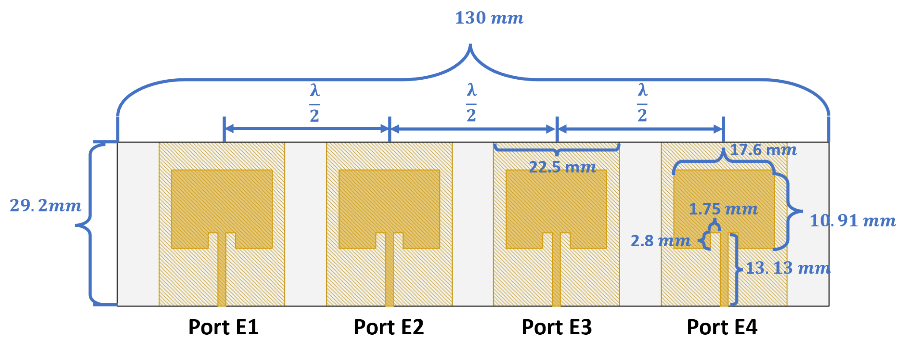
5.1. Design of a Single Patch Antenna Array

To demonstrate our approach, we design a four-element microstrip rectangular patch antenna array at 5.2 GHz (see Figure 2). Our antenna array, as well as our Butler matrix, are designed on FR4 boards with a dielectric constant of ϵ r = 4.4 and thickness of t = 0.72 mm. For a N-element array, the array factor (AF) reads as follows [62]:
A F = n = 0 N e j ( n 1 ) ψ
A four-element rectangular microstrip patch antenna is designed and shown in Figure 3 with element spacing of half wavelength at the designed center frequency of 5.2 GHz.

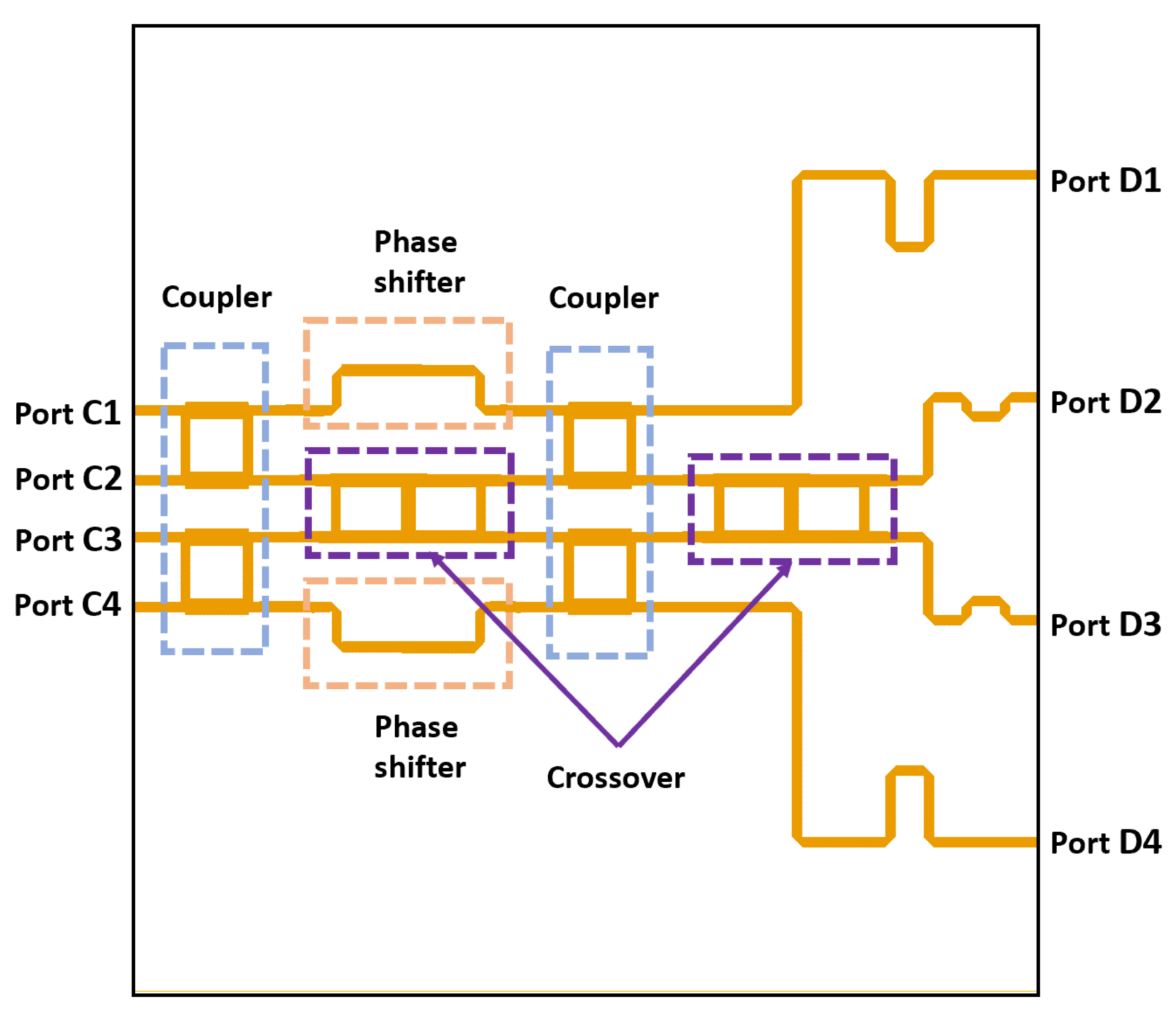
5.2. Design of Butler Matrix Network

To achieve switched-beam functionality in our antenna array, a MIMO beamforming network is required. For this, we utilize a linear, passive feeding beamforming network [63]. Among the various passive microstrip beamforming technologies, such as the Butler matrix [63], microstrip lens [64], Blass matrix [65], and Nolen matrix [66], we selected the Butler matrix for its advantage in easy fabrication and precise control over output beam phases. The Butler matrix is a passive beamformer with an equal number of inputs and outputs [63], making it ideal for our proposed STAR system. Additionally, it performs a spatial fast Fourier transform, generating N orthogonal beams [63]. The conventional Butler matrix consists of couplers, crossovers, and phase shifters. Figure 4 shows the designed microstrip-based 4 × 4 Butler matrix structure, while Table 2 lists the phase differences between outputs for various excitations. As it can be seen, the Butler matrix is a passive beamformer that has the same number of inputs and ouputs [67]. Meanwhile, the Butler matrix performs a spatial fast Fourier transform and provides N orthogonal beams [63].

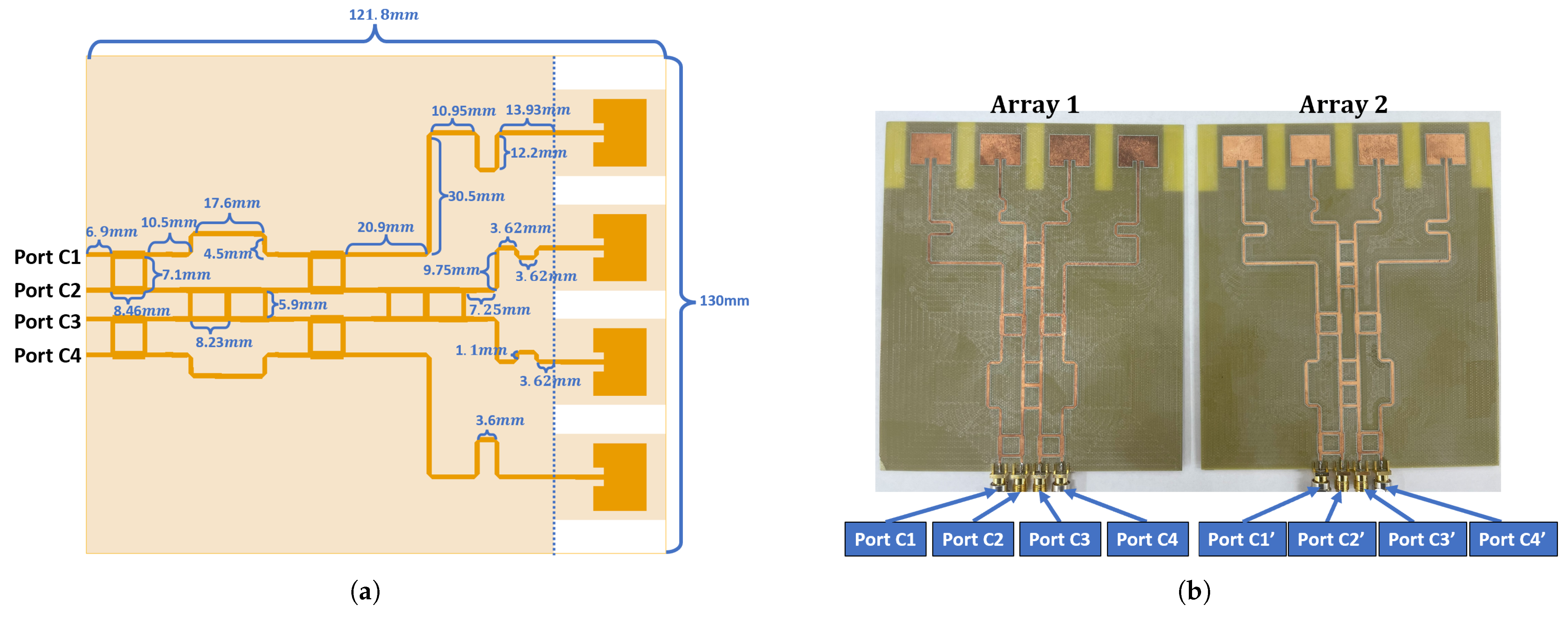
5.3. Design of an Integrated Antenna Array with a Butler Matrix
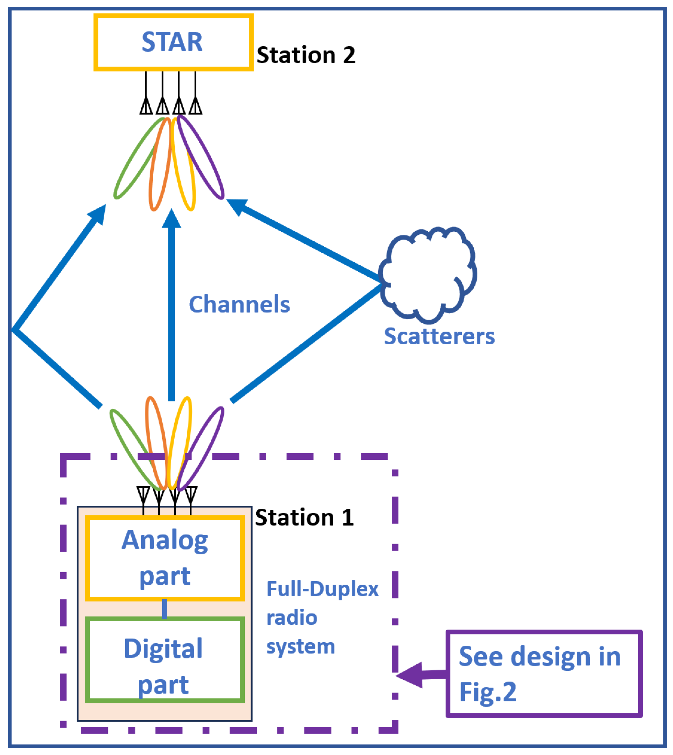
By combining the designed antenna array with our Butler matrix, we obtain an integrated microstrip-based antenna array with a beamformer. Figure 5a shows the design of the integrated 4 × 4 antenna array. Notably, the Butler matrix is designed to operate at 5.2 GHz. Figure 5b presents the fabricated twin array of the passive beamforming system. The passive beamforming circuit is fabricated on an FR4 board with a thickness of h = 0.72 mm and an overall size of 121.8 × 130 mm2.
The measured and simulated radiation patterns of the antenna array systems are shown in Figure 6. Ports C1 and C4 in Figure 5a demonstrate better side-lobe control at ϕ = 90 compared to the other two ports, while the side lobes for beams excited at ports C2 and C3 slightly degraded. The slight variations between the two are attributed to fabrication imperfections and the compact size of the antenna array.
Figure 7 presents the simulated and measured S parameters of the two antenna array systems shown in Figure 5. Minor discrepancies between the measured and simulated results are observed, primarily due to fabrication tolerances. Notably, the designed Butler matrix achieves an average isolation of approximately −25 dB between different ports without additional optimization.

6. MIMO STAR System

In the previous section, we proposed the mathematical model of the twin Butler matrix array. In this section, we present the fabrication and measurement of the full-duplex (FD) MIMO STAR system incorporating the Butler matrix.
The proposed full-duplex MIMO STAR system is shown in Figure 8. It includes 180 couplers, which represent four inputs and outputs, as well as two Butler matrices integrated with rectangular microstrip patch antennas. The Butler matrix and antenna array on the left, placed in the RF anechoic chamber, function as a reference array to provide a copy of the interference signal; this has a 180 phase difference from the interference signal received by the right antenna array.
The four Tx ports in Figure 8 are labeled T1 through T4, while the four Rx ports are labeled R1 through R4. Figure 8b shows the connections of the proposed system. Instead of using SMA connectors to connect the Butler matrix and the couplers, coaxial cables were used. To facilitate easier measurements, the four couplers were separated into individual components.

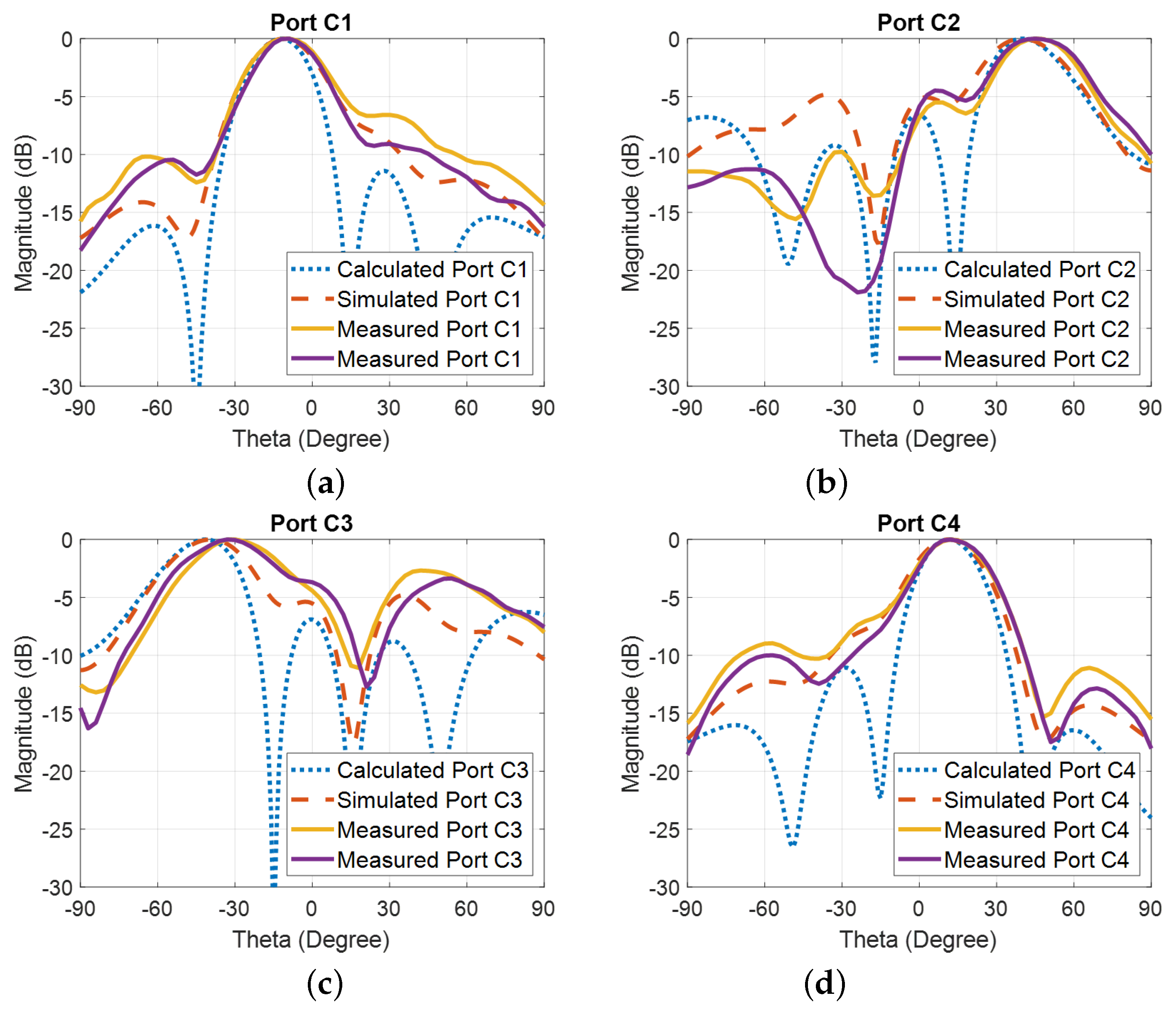
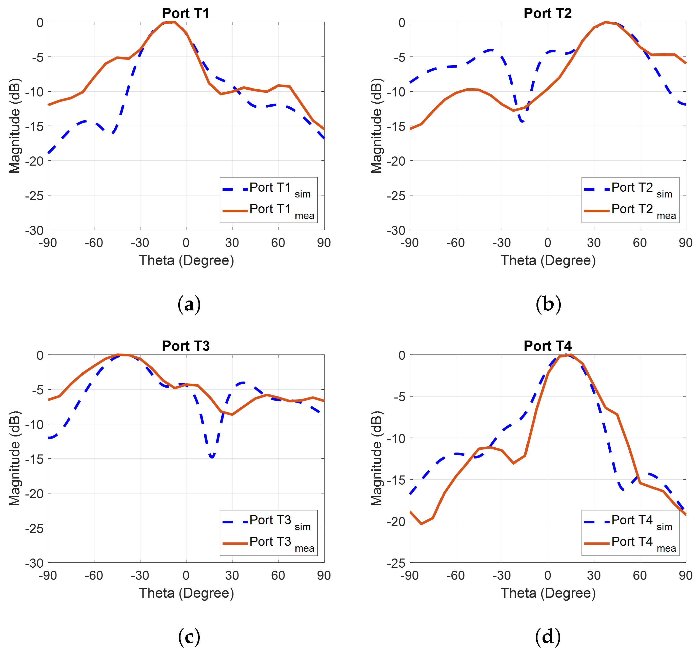
6.1. Radiated Beam-Measured Results

The normalized beams of the proposed STAR system shown in Figure 8 are measured and presented in Figure 9. When compared with the beams of the single beamformer in Figure 6, the proposed system maintains a similar beam shape. However, since side-lobe optimization was not applied during the system design, the beams for ports T2 and T3 exhibit suboptimal performance compared to the other two ports. Side-lobe optimization will be addressed in a future work.

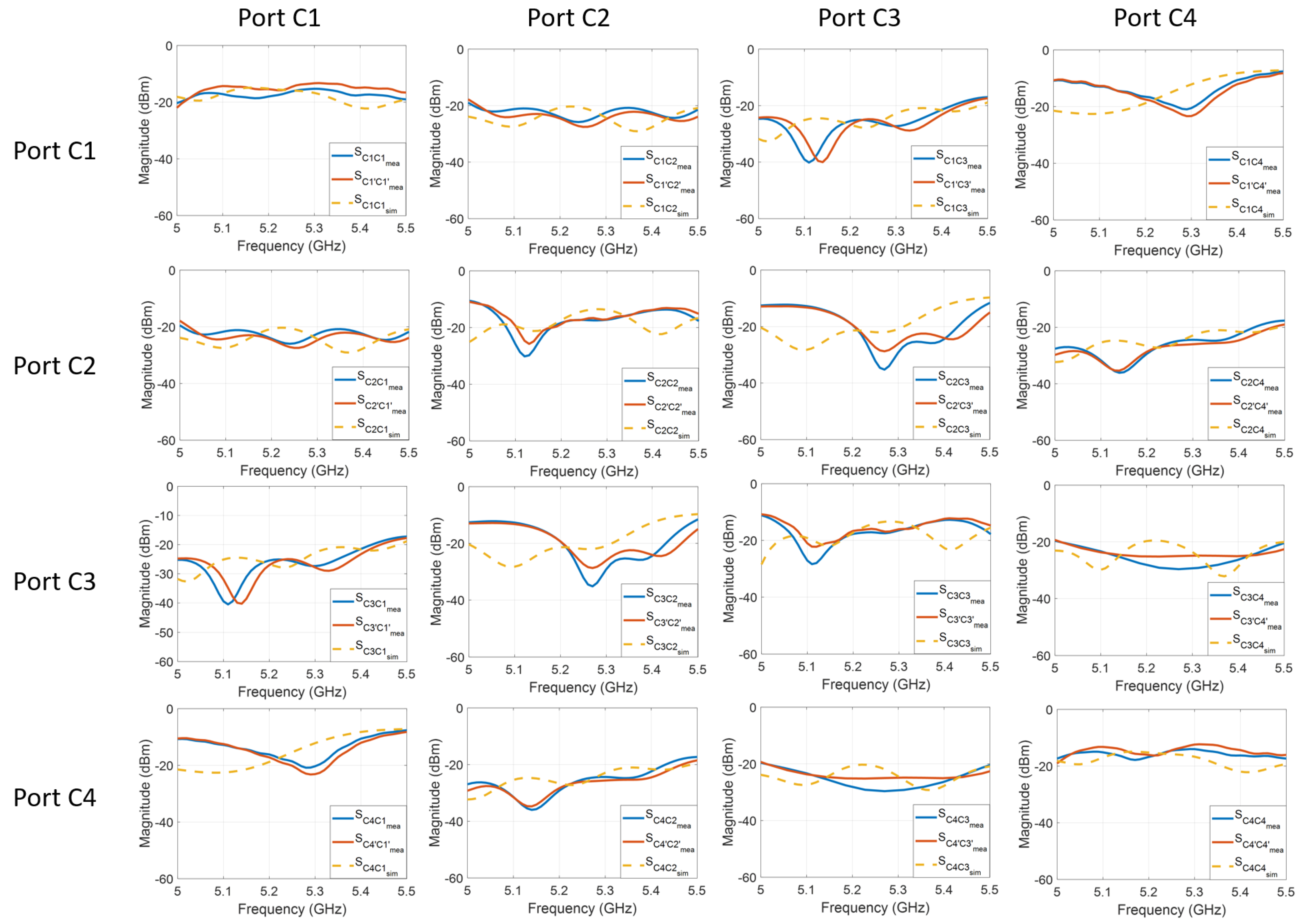
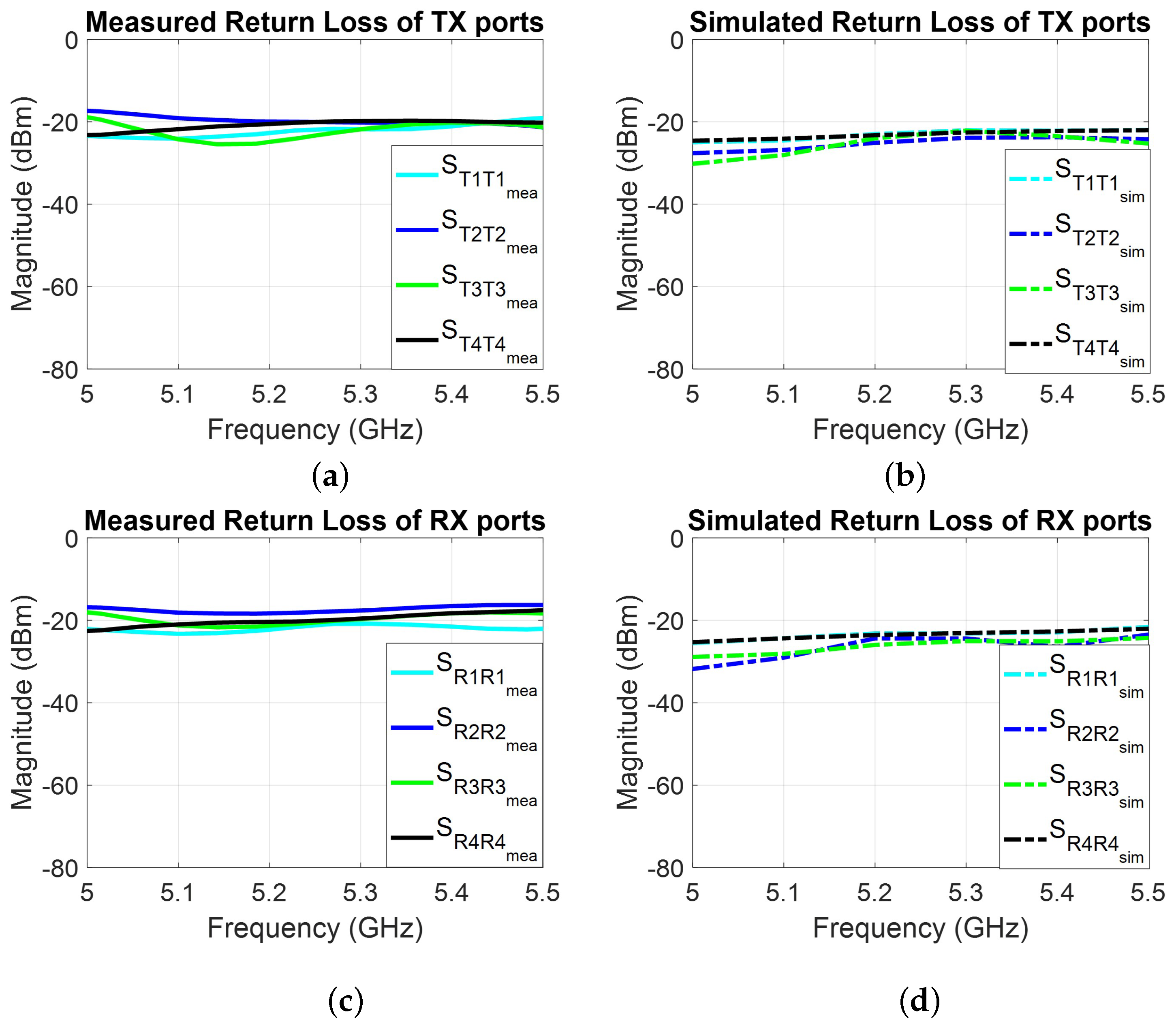
6.2. Measured System Return Loss

Figure 10a presents the measured return losses for the Tx ports (T1 to T4), while Figure 10c shows the measured return losses for the Rx ports (R1 to R4). For comparison, the corresponding simulated results for the Tx and Rx ports are displayed in Figure 10b and Figure 10d, respectively. The fabricated FD system demonstrates good agreement with the simulations. The return loss for all ports is approximately −20 dB across the 5.0 to 5.5 GHz frequency range. Notably, the return loss performance of the proposed system is influenced by the performance of the coupler ports. With further improvements in the coupler design, the system’s return loss is expected to improve.

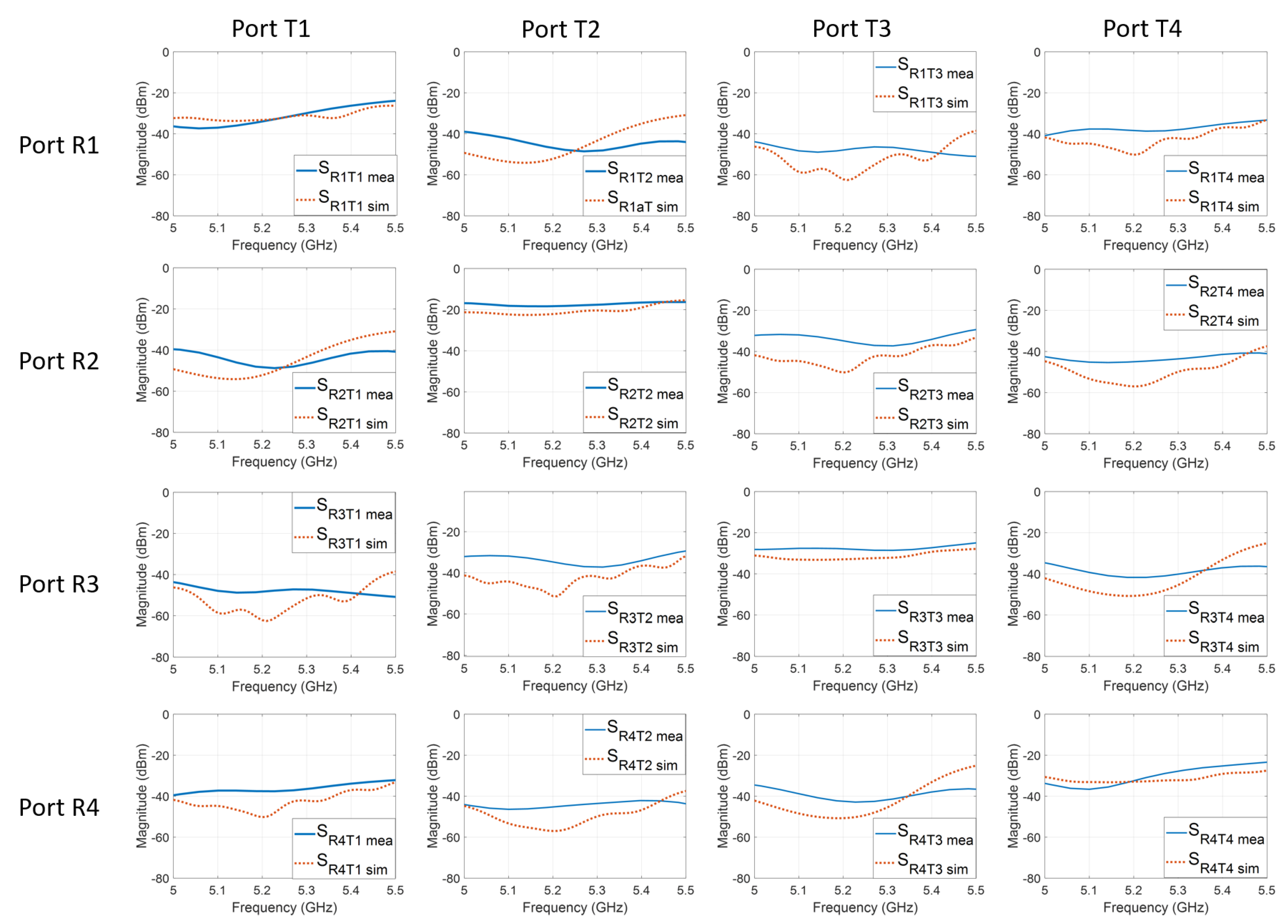
6.3. Designed Ports’ Isolation-Measured Results

The measured coupling between the ports of the proposed system, compared to the simulated results, is shown in Figure 11. The diagonal entries in Figure 11 represent the self-isolation of the system when connected to a single coupler. Compared with ports T2 and T3, the self-isolation for ports T1 and T4 are better, since there is no optimal side-lobe control for port T2 and port T3, as shown in Figure 6.
The off-diagonal entries show the coupling between different transmitter (row) and receiver (column) ports. The measured couplings between transmitter and receiver ports achieve isolation levels below −40 dB at the target frequency of 5.2 GHz, with an average isolation of −40 dB across the 5 to 5.5 GHz frequency range. The simulated system performance is marked in red-dashed lines in Figure 11, while the measured system performance is marked in blue. Although the measured isolation is lower than the simulation results, likely due to the use of a long cable during measurement for improved accuracy, the application of the proposed twin-Butler structure still results in an isolation improvement of over 20 dB between the different Rx and Tx ports.

7. Conclusions

This article presented a unique microstrip technology-based twin-array STAR approach with low complexity suitable for MIMO beamforming systems. By applying such an approach, the MIMO system achieves ∼40 dB isolation between Tx and Rx ports across all elements, without the use of any sophisticated algorithm. Meanwhile, system redundancy is reduced by only applying simple printed microstrip circuits. The proposed approach also addresses the near-field coupling issue between antenna elements in an array, which can significantly affect isolation performance in multi-element antenna array MIMO systems. Consequently, near-field mutual coupling can be controlled, and the system SIC can then be improved. Although the proposed system requires an additional antenna array and beamformer, which may effectively double the system cost, it can still reduce the overall expenses associated with complex system design and the enhancement of system SIC, which could be significantly more expensive than the additional components. Another advantage of our proposed system is the ability to maintain the desired SIC of 40 dB while the antenna array steers its beams. Compared to other existing MIMO systems, our system maintains a strong figure of merit performance, taking into account both the isolation and percentage bandwidth.

Author Contributions

Conceptualization, Y.Z., S.B.V., C.L.Z. and A.M.; methodology, Y.Z., S.B.V., C.L.Z., S.M. and A.M.; validation, Y.Z., S.B.V., C.L.Z., S.M. and A.M.; formal analysis, Y.Z., S.B.V. and A.M.; investigation, Y.Z., S.B.V., C.L.Z., S.M. and A.M.; writing—original draft, Y.Z., S.B.V., C.L.Z. and A.M.; writing—review & editing, Y.Z., S.B.V., C.L.Z., S.M. and A.M.; supervision, S.B.V., C.L.Z., S.M. and A.M.; project administration, S.B.V. and A.M.; funding acquisition, S.B.V. and A.M. All authors have read and agreed to the published version of the manuscript.

Funding

This research was funded by the NSF under the grant 2104879.

Institutional Review Board Statement

Not applicable.

Informed Consent Statement

Not applicable.

Data Availability Statement

The original contributions presented in this study are included in the article. Further inquiries can be directed to the corresponding author.

Acknowledgments

The authors would like to thank the FIU RFcom lab, TAC lab, and RAND lab for their continued support in the fabrication and validation of the prototype. Special thanks are also extended to Wupeng Yin for her contributions to formatting the manuscript.

Conflicts of Interest

The authors declare no conflicts of interest.

References

  1. John, D.M.; Vincent, S.; Pathan, S.; Kumar, P.; Ali, T. Flexible Antennas for a Sub-6 GHz 5G Band: A Comprehensive Review. Sensors 2022, 22, 7615. [Google Scholar] [CrossRef] [PubMed]
  2. Yao, G.; Hashemi, M.; Singh, R.; Shroff, N.B. Delay-Optimal Scheduling for Integrated mmWave – Sub-6 GHz Systems With Markovian Blockage Model. IEEE Trans. Mob. Comput. 2023, 22, 5124–5139. [Google Scholar] [CrossRef]
  3. Pirayesh, H.; Zeng, H. Jamming Attacks and Anti-Jamming Strategies in Wireless Networks: A Comprehensive Survey. IEEE Commun. Surv. Tutor. 2022, 24, 767–809. [Google Scholar] [CrossRef]
  4. Smida, B.; Sabharwal, A.; Fodor, G.; Alexandropoulos, G.C.; Suraweera, H.A.; Chae, C.B. Full-Duplex Wireless for 6G: Progress Brings New Opportunities and Challenges. IEEE J. Sel. Areas Commun. 2023, 41, 2729–2750. [Google Scholar] [CrossRef]
  5. Skokowski, P.; Kelner, J.M.; Malon, K.; Maślanka, K.; Birutis, A.; Vazquez, M.A.; Saha, S.; Low, W.; Czapiewska, A.; Magiera, J.; et al. Jamming and Jamming Mitigation for Selected 5G Military Scenarios. Procedia Comput. Sci. 2022, 205, 258–267. [Google Scholar] [CrossRef]
  6. Zhao, H.; De Silva, U.; Pulipati, S.; Venkatakrishnan, S.B.; Bhardwaj, S.; Volakis, J.L.; Mandal, S.; Madanayake, A. A Broadband Multistage Self-Interference Canceller for Full-Duplex MIMO Radios. IEEE Trans. Microw. Theory Tech. 2021, 69, 2253–2266. [Google Scholar] [CrossRef]
  7. Dehghanzadeh, P.; Madanayake, A.; Zhao, H.; Venkatakrishnan, S.B.; Mandal, S. A Multiport Self-Interference Canceller for Wideband SIMO/MIMO-STAR Full-Duplex Arrays. IEEE Trans. Microw. Theory Tech. 2023, 72, 2640–2654. [Google Scholar] [CrossRef]
  8. Bojja Venkatakrishnan, S.; Papantonis, D.K.; Akhiyat, A.A.; Alwan, E.A.; Volakis, J.L. Experimental Validation of On-Site Coding Digital Beamformer With Ultra-Wideband Antenna Arrays. IEEE Trans. Microw. Theory Tech. 2017, 65, 4408–4417. [Google Scholar] [CrossRef]
  9. Venkatakrishnan, S.B.; Hovsepian, A.; Johnson, A.D.; Nakatani, T.; Alwan, E.A.; Volakis, J.L. Techniques for Achieving High Isolation in RF Domain for Simultaneous Transmit and Receive. IEEE Open J. Antennas Propag. 2020, 1, 358–367. [Google Scholar] [CrossRef]
  10. Bojja Venkatakrishnan, S.; Alwan, E.A.; Volakis, J.L. Wideband RF Self-Interference Cancellation Circuit for Phased Array Simultaneous Transmit and Receive Systems. IEEE Access 2018, 6, 3425–3432. [Google Scholar] [CrossRef]
  11. Foschini, G.; Golden, G.; Valenzuela, R.; Wolniansky, P. Simplified Processing for High Spectral Efficiency Wireless Communication Employing Multi-Element Arrays. IEEE J. Sel. Areas Commun. 1999, 17, 1841–1852. [Google Scholar] [CrossRef]
  12. Mohammadi, M.; Suraweera, H.A.; Krikidis, I.; Tellambura, C. Full-Duplex Radio for Uplink/Downlink Transmission with Spatial Randomness. In Proceedings of the 2015 IEEE International Conference on Communications (ICC), London, UK, 8–12 June 2015; pp. 1908–1913. [Google Scholar] [CrossRef]
  13. Yonis, A.; Abdullah, M.F.L.; Ghanim, M. LTE-FDD and LTE-TDD for cellular communications. In Proceedings of the Progress in Electromagnetics Research Symposium Proceedings, Kuala Lumpur, Malaysia, 27–30 March 2012. [Google Scholar]
  14. Kolodziej, K.E. In-Band Full-Duplex Wireless Systems Handbook; Artech House: Norwood, MA, USA, 2021. [Google Scholar]
  15. Rahman, M.A.; Rahman, M.M.; Alim, M.A. Design and Performance Analysis of an In-Band Full-Duplex MAC Protocol for Ad Hoc Networks. Telecom 2023, 4, 100–117. [Google Scholar] [CrossRef]
  16. Songzuo, L.; Iqbal, B.; Khan, I.U.; Ahmed, N.; Qiao, G.; Zhou, F. Full Duplex Physical and MAC layer-based Underwater Wireless Communication Systems and Protocols: Opportunities, challenges, and Future Directions. J. Mar. Sci. Eng. 2021, 9, 468. [Google Scholar] [CrossRef]
  17. Singh, K.; Wang, P.C.; Biswas, S.; Singh, S.K.; Mumtaz, S.; Li, C.P. Joint Active and Passive Beamforming Design for RIS-aided IBFD IoT communications: QoS and Power Efficiency Considerations. IEEE Trans. Consum. Electron. 2022, 69, 170–182. [Google Scholar] [CrossRef]
  18. Hassani, S.A.; Guevara, A.; Parashar, K.; Bourdoux, A.; van Liempd, B.; Pollin, S. An In-band Full-Duplex Transceiver for Simultaneous Communication and Environmental Sensing. In Proceedings of the 2018 52nd Asilomar Conference on Signals, Systems, and Computers, Pacific Grove, CA, USA, 28–31 October 2018; pp. 1389–1394. [Google Scholar]
  19. Cox, C.H.; Ackerman, E.I. Photonics for Simultaneous Transmit and Receive. In Proceedings of the 2011 IEEE MTT-S International Microwave Symposium, Baltimore, MD, USA, 5–10 June 2011; pp. 1–4. [Google Scholar] [CrossRef]
  20. Raghavan, V.; Sayeed, A.M. Sublinear Capacity Scaling Laws for Sparse MIMO Channels. IEEE Trans. Inf. Theory 2010, 57, 345–364. [Google Scholar] [CrossRef]
  21. Sohrabi, F.; Yu, W. Hybrid Digital and Analog Beamforming Design for Large-Scale MIMO systems. In Proceedings of the 2015 IEEE International Conference on Acoustics, Speech and Signal Processing (ICASSP), South Brisbane, QLD, Australia, 19–24 April 2015; pp. 2929–2933. [Google Scholar]
  22. Zhao, Y.; Venkatakrishnan, S.B.; Zekios, C.L.; Mandal, S.; Madanayake, A. Differential Arrays for Butler Multi-Beam STAR. In Proceedings of the 2024 International Applied Computational Electromagnetics Society Symposium (ACES), Orlando, FL, USA, 19–22 May 2024; pp. 1–2. [Google Scholar]
  23. Buinevich, M.; Vladyko, A. Forecasting Issues of Wireless Communication Networks’ cyber Resilience for an Intelligent Transportation System: An overview of cyber Attacks. Information 2019, 10, 27. [Google Scholar] [CrossRef]
  24. Bojja Venkatakrishnan, S. Simultaneous Transmit/Receive Multi-Functional Ultra-Wideband Transceiver with Reduced Hardware. Ph.D. Thesis, The Ohio State University, Columbus, OH, USA, 2017. [Google Scholar]
  25. Venkatakrishnan, S.B.; Hovsepian, A.; Volakis, J.L. Antenna Agnostic Feed Cancellation STAR System for Improved Cancellation. URSI Radio Sci. Bull. 2020, 2020, 46–53. [Google Scholar] [CrossRef]
  26. Bharadia, D.; Katti, S. Full Duplex MIMO Radios. In Proceedings of the 11th USENIX Symposium on Networked Systems Design and Implementation (NSDI 14), Seattle, WA, USA, 2–4 April 2014; pp. 359–372. [Google Scholar]
  27. Khaledian, S.; Farzami, F.; Smida, B.; Erricolo, D. Inherent Self-Interference Cancellation for In-Band Full-Duplex Single-Antenna Systems. IEEE Trans. Microw. Theory Tech. 2018, 66, 2842–2850. [Google Scholar] [CrossRef]
  28. Scherer, K.L.; Watt, S.J.; Alwan, E.A.; Akhiyat, A.A.; Dupaix, B.; Khalil, W.; Volakis, J.L. Simultaneous Transmit and Receive System Architecture with Four Stages of Cancellation. In Proceedings of the 2015 IEEE International Symposium on Antennas and Propagation & USNC/URSI National Radio Science Meeting, Vancouver, BC, Canada, 19–24 July 2015; pp. 520–521. [Google Scholar]
  29. Khojastepour, M.A.; Sundaresan, K.; Rangarajan, S.; Zhang, X.; Barghi, S. The Case for Antenna Cancellation for Scalable Full-Duplex Wireless Communications. In Proceedings of the 10th ACM Workshop on Hot Topics in Networks, Cambridge, MA, USA, 14–15 November 2011; pp. 1–6. [Google Scholar]
  30. Martin, K.; Psychogiou, D. Enhanced In-Band Self-Interference Suppression by Combining Bandpass Filter-Based RF Cancellers and Dual-Polarized Antennas. In Proceedings of the 2024 IEEE/MTT-S International Microwave Symposium—IMS 2024, Washington, DC, USA, 16–21 June 2024; pp. 741–744. [Google Scholar] [CrossRef]
  31. Elzayat, A.M.; Kouki, A.B. Tx/Rx Isolation Enhancement Based on a Novel Balanced Duplexer Architecture. In Proceedings of the 2011 IEEE MTT-S International Microwave Symposium, Baltimore, MD, USA, 5–10 June 2011; pp. 1–4. [Google Scholar] [CrossRef]
  32. Lin, J.Y.; Wong, S.W.; Yang, Y. Filtering In-Band Full-Duplex Slot Antenna Based on TM120 and TM210 Dual-Mode Resonators. In Proceedings of the 2021 IEEE MTT-S International Microwave Filter Workshop (IMFW), Perugia, Italy, 17–19 November 2021; pp. 249–251. [Google Scholar] [CrossRef]
  33. Schwartz, Y.; Cohen, E. An Ultra-Compact Wideband Tunable Autotransformer-Based Electrical-Balanced Duplexer Achieving 30 dB Isolation Across the 46–70 GHz Frequency Range. In Proceedings of the 2024 IEEE/MTT-S International Microwave Symposium—IMS 2024, Washington, DC, USA, 16–21 June 2024; pp. 446–449. [Google Scholar] [CrossRef]
  34. Cryan, M.; Hall, P.; Tsang, S.; Sha, J. Integrated Active Antenna with Full Duplex Operation. IEEE Trans. Microw. Theory Tech. 1997, 45, 1742–1748. [Google Scholar] [CrossRef]
  35. Dastjerdi, M.B.; Reiskarimian, N.; Chen, T.; Zussman, G.; Krishnaswamy, H. Full Duplex Circulator-Receiver Phased Array Employing Self-Interference Cancellation via Beamforming. In Proceedings of the 2018 IEEE Radio Frequency Integrated Circuits Symposium (RFIC), Philadelphia, PA, USA, 10–12 June 2018; pp. 108–111. [Google Scholar] [CrossRef]
  36. Shi, C.; Pan, W.; Shao, S. RF Wideband Self-Interference Cancellation for Full Duplex Phased Array Communication Systems. In Proceedings of the ICC 2022—IEEE International Conference on Communications, Seoul, Republic of Korea, 16–20 May 2022; pp. 1094–1099. [Google Scholar] [CrossRef]
  37. Roberts, I.P.; Jain, H.B.; Vishwanath, S. Equipping Millimeter-Wave Full-Duplex with Analog Self-Interference Cancellation. In Proceedings of the 2020 IEEE International Conference on Communications Workshops (ICC Workshops), Dublin, Ireland, 7–11 June 2020; pp. 1–6. [Google Scholar] [CrossRef]
  38. Masmoudi, A.; Le-Ngoc, T. Self-Interference Cancellation for Full-Duplex MIMO Transceivers. In Proceedings of the 2015 IEEE Wireless Communications and Networking Conference (WCNC), New Orleans, LA, USA, 9–12 March 2015; pp. 141–146. [Google Scholar] [CrossRef]
  39. Dastjerdi, M.B.; Chen, T.; Reiskarimian, N.; Zussman, G.; Krishnaswamy, H. Self-Interference Cancellation via Beamforming in an Integrated Full Duplex Circulator-Receiver Phased Array. In Proceedings of the 2018 International Conference on Signal Processing and Communications (SPCOM), Bangalore, India, 16–19 July 2018; pp. 437–441. [Google Scholar] [CrossRef]
  40. Park, K.; Myeong, J.; Rebeiz, G.M.; Min, B.W. A 28-GHz Full-Duplex Phased Array Front-End Using Two Cross-Polarized Arrays and a Canceller. IEEE Trans. Microw. Theory Tech. 2021, 69, 1127–1135. [Google Scholar] [CrossRef]
  41. Wegener, A.T. Broadband Near-Field Filters for Simultaneous Transmit and Receive in a Small Two-Dimensional Array. In Proceedings of the 2014 IEEE MTT-S International Microwave Symposium (IMS2014), Tampa, FL, USA, 1–6 June 2014; pp. 1–3. [Google Scholar] [CrossRef]
  42. Lin, J.Y.; Yang, Y.; Wong, S.W.; Chen, R.S. In-Band Full-Duplex Filtering Antenna Arrays Using High-Order Mode Cavity Resonators. IEEE Trans. Microw. Theory Tech. 2023, 71, 1630–1639. [Google Scholar] [CrossRef]
  43. Le, A.T.; Huang, X.; Guo, Y.J. Analog Self-Interference Cancellation in Dual-Polarization Full-Duplex MIMO Systems. IEEE Commun. Lett. 2021, 25, 3075–3079. [Google Scholar] [CrossRef]
  44. Lee, C.; Khattak, M.K.; Kahng, S. Wideband 5G Beamforming Printed Array Clutched by LTE-A 4 × 4-multiple-input–multiple-output antennas with High Isolation. IET Microwaves Antennas Propag. 2018, 12, 1407–1413. [Google Scholar] [CrossRef]
  45. Kiani, S.H.; Savci, H.S.; Munir, M.E.; Sedik, A.; Mostafa, H. An Ultra-Wide Band MIMO Antenna System with Enhanced Isolation for Microwave Imaging Applications. Micromachines 2023, 14, 1732. [Google Scholar] [CrossRef] [PubMed]
  46. Roshna, T.K.; Deepak, U.; Sajitha, V.R.; Vasudevan, K.; Mohanan, P. A Compact UWB MIMO Antenna with Reflector to Enhance Isolation. IEEE Trans. Antennas Propag. 2015, 63, 1873–1877. [Google Scholar] [CrossRef]
  47. Tsakalaki, E.; Foroozanfard, E.; de Carvalho, E.; Pedersen, G.F. A 2-order MIMO full-duplex antenna system. In Proceedings of the The 8th European Conference on Antennas and Propagation (EuCAP 2014), The Hague, The Netherlands, 6–11 April 2014; pp. 2546–2550. [Google Scholar] [CrossRef]
  48. Li, M.; Jiang, L.; Yeung, K.L. A General and Systematic Method to Design Neutralization Lines for Isolation Enhancement in MIMO Antenna Arrays. IEEE Trans. Veh. Technol. 2020, 69, 6242–6253. [Google Scholar] [CrossRef]
  49. Zou, H.; Li, Y.; Xu, B.; Chen, Y.; Jin, H.; Yang, G.; Luo, Y. Dual-Functional MIMO Antenna Array With High Isolation for 5G/WLAN Applications in Smartphones. IEEE Access 2019, 7, 167470–167480. [Google Scholar] [CrossRef]
  50. Li, Y.; Sim, C.Y.D.; Luo, Y.; Yang, G. High-Isolation 3.5 GHz Eight-Antenna MIMO Array Using Balanced Open-Slot Antenna Element for 5G Smartphones. IEEE Trans. Antennas Propag. 2019, 67, 3820–3830. [Google Scholar] [CrossRef]
  51. Sokunbi, O.; Attia, H. Dual-layer Dual-patch EBG Structure for Isolation Enhancement and Correlation Reduction in MIMO Antenna Arrays. Prog. Electromagn. Res. C 2020, 100, 233–245. [Google Scholar] [CrossRef]
  52. Chen, Y.N.; Ding, C.; Liu, Y.; Guo, Y.J. A Four-Port Shared-Aperture In-Band Full-Duplex Antenna Array Based on Modes Combination Method. In Proceedings of the 2024 IEEE International Conference on Computational Electromagnetics (ICCEM), Nanjing, China, 15–17 April 2024; pp. 1–3. [Google Scholar] [CrossRef]
  53. Sepanek, R.; Hickle, M.; Stuenkel, M. In-Band Full-Duplex Self-Interference Canceller Augmented with Bandstop-Configured Resonators. In Proceedings of the 2020 IEEE/MTT-S International Microwave Symposium (IMS), Los Angeles, CA, USA, 4–6 August 2020; pp. 1199–1202. [Google Scholar] [CrossRef]
  54. Nagulu, A.; Mekkawy, A.; Tymchenko, M.; Sounas, D.; Alù, A.; Krishnaswamy, H. Ultra-Wideband Switched-Capacitor Delays and circulators—Theory and Implementation. IEEE J.-Solid State Circuits 2021, 56, 1412–1424. [Google Scholar] [CrossRef]
  55. Malathi, A.C.J.; Thiripurasundari, D. Review on Isolation Techniques in MIMO Antenna systems. Indian J. Sci. Technol. 2016, 9, 1–10. [Google Scholar]
  56. Silva, U.D.; Pulipati, S.; Venkatakrishnan, S.B.; Bhardwaj, S.; Madanayake, A. A Passive STAR Microwave Circuit for 1-3 GHz Self-Interference Cancellation. In Proceedings of the 2020 IEEE 63rd International Midwest Symposium on Circuits and Systems (MWSCAS), Springfield, MA, USA, 9–12 August 2020; pp. 105–108. [Google Scholar] [CrossRef]
  57. Jonsson, J.C.; Smith, G.B.; Niklasson, G.A. Experimental and Monte Carlo analysis of isotropic multiple Mie scattering. Opt. Commun. 2004, 240, 9–17. [Google Scholar] [CrossRef]
  58. Zhensen, W.; Yi, Y.; Lihong, C. Monte Carlo simulation for millimeter wave propagation and scattering in rain medium. Int. J. Infrared Millim. Waves 1992, 13, 981–994. [Google Scholar] [CrossRef]
  59. Isabona, J.; Imoize, A.L.; Ojo, S.; Lee, C.C.; Li, C.T. Atmospheric Propagation Modelling for Terrestrial Radio Frequency Communication Links in a Tropical Wet and Dry Savanna Climate. Information 2022, 13, 141. [Google Scholar] [CrossRef]
  60. Kotake, H.; Abe, Y.; Kolev, D.R.; Saito, Y.; Takahashi, Y.; Fuse, T.; Satoh, Y.; Itahashi, T.; Yamakawa, S.; Tsuji, H.; et al. Experimental analysis of atmospheric channel model with misalignment fading for GEO satellite-to-ground optical link using “LUCAS” onboard optical data relay satellite. Opt. Express 2023, 31, 21351–21366. [Google Scholar] [CrossRef]
  61. Jiang, S.; Wang, W.; Miao, Y.; Fan, W.; Molisch, A.F. A Survey of Dense Multipath and Its Impact on Wireless Systems. IEEE Open J. Antennas Propag. 2022, 3, 435–460. [Google Scholar] [CrossRef]
  62. Balanis, C.A. Antenna Theory: Analysis and Design; John Wiley & Sons: Hoboken, NJ, USA, 2016. [Google Scholar]
  63. Balanis, C.; Ioannides, P. Introduction to smart antennas. Synth. Lect. Antennas 2007, 5, 1–179. [Google Scholar] [CrossRef]
  64. Vashist, S.; Soni, M.; Singhal, P. A review on the Development of Rotman Lens Antenna. Chin. J. Eng. 2014, 2014, 385385. [Google Scholar] [CrossRef]
  65. Mosca, S.; Bilotti, F.; Toscano, A.; Vegni, L. A Novel Design Method for Blass matrix Beam-Forming Networks. IEEE Trans. Antennas Propag. 2002, 50, 225–232. [Google Scholar] [CrossRef]
  66. Fonseca, N.J.G. Printed S-Band 4 × 4 Nolen Matrix for Multiple Beam Antenna Applications. IEEE Trans. Antennas Propag. 2009, 57, 1673–1678. [Google Scholar] [CrossRef]
  67. Comitangelo, R.; Minervini, D.; Piovano, B. Beam Forming Networks of Optimum Size and Compactness for Multibeam Antennas at 900 MHz. In Proceedings of the IEEE Antennas and Propagation Society International Symposium 1997. Digest, Montreal, QC, Canada, 13–18 July 1997; Volume 4, pp. 2127–2130. [Google Scholar] [CrossRef]
Figure 1. Overview of the STAR MIMO radio system.
Information 16 00321 g001
Figure 2. Proposed full-duplex system: (a) Proposed N-element FD system diagram block. (b) Designed four-element linear antenna array FD system.
Information 16 00321 g002
Figure 3. Schematic of the designed 4-element patch antenna array (port width = 1.4 mm).
Information 16 00321 g003
Figure 4. Schematic of the designed 4 × 4 microstrip Butler matrix.
Information 16 00321 g004
Figure 5. Design of the Butler matrix integrated with the antenna array: (a) Schematic of the EM design. (b) Fabricated prototype.
Information 16 00321 g005
Figure 6. Normalized measured and simulated results of the two Butler matrix array systems of Figure 5 (at ϕ = 90 , f = 5.2 GHz).
Information 16 00321 g006
Figure 7. Measured S parameters for the two designs shown in Figure 5.
Information 16 00321 g007
Figure 8. Layout of our proposed full-duplex MIMO system: (a) Layout in simulation. (b) Fabricated system.
Information 16 00321 g008
Figure 9. Normalized simulated and measured realized gain (at ϕ = 90 , f = 5.2 GHz) of the complete system shown in Figure 8.
Information 16 00321 g009
Figure 10. Normalized simulated and measured realized gain (at ϕ = 90 , f = 5.2 GHz) of the complete system shown in Figure 8.
Information 16 00321 g010
Figure 11. Measured FD system isolation in Figure 8.
Information 16 00321 g011
Table 1. Comparison table of state-of-the-art MIMO beamforming systems.
ReferenceTechnologyConnection TypeAverage Isolation (dB)Center Frequency (GHz)Bandwidth (GHz)Metric M 1 *
[47]MicrostripDiscrete502.580.013.88
[48]MicrostripDiscrete252.40.20.26
[43]MicrostripIntegrated402.40.041.67
[49]MicrostripDiscrete34.63.50.21.65
[50]MicrostripDiscrete203.50.20.06
[44]MicrostripIntegrated382.50.37.57
[45]CPW-fed MicrostripIntegrated25741.80
[51]EBG MicrostripIntegrated355.81.47.63
[46]CPS-fed StriplineIntegrated25783.61
[30]MicrostripDiscrete502.40.028.33
[33]TSMC 65 nm CMOSIntegrated3060193.17
[41]MicrostripIntegrated303.450.10.3
[27]MicrostripIntegrated402.450.0652.61
[34]MicrostripIntegrated454.040.021.57
[40]MicrostripDiscrete45280.55.65
[52]MicrostripDiscrete383.50.59.01
This workMicrostripDiscrete405.20.59.62
* Metric M 1 is defined in Equation (1).
Table 2. Output ports phase of the designed Butler matrix.
Port NamePort C1Port C2Port C3Port C4
Port D1135°45°75°
Port D290°180°−60°50°
Port D345°−45°165°95°
Port D490°30°130°
Phase Difference−45°135°−135°45°
Disclaimer/Publisher’s Note: The statements, opinions and data contained in all publications are solely those of the individual author(s) and contributor(s) and not of MDPI and/or the editor(s). MDPI and/or the editor(s) disclaim responsibility for any injury to people or property resulting from any ideas, methods, instructions or products referred to in the content.

