Abstract
The demand for communicating large amounts of data in real-time has raised new challenges with implementing high-speed communication paths for high definition video and sensory data. It requires the implementation of high speed data paths based on hardware. Implementation difficulties have to be addressed by applying new techniques based on data-oriented algorithms. This paper focuses on a solution for this problem by applying a lossless data compression mechanism on the communication data path. The new lossless data compression mechanism, called LCA-DLT, provides dynamic histogram management for symbol lookup tables used in the compression and the decompression operations. When the histogram memory is fully used, the management algorithm needs to find the least used entries and invalidate these entries. The invalidation operations cause the blocking of the compression and the decompression data stream. This paper proposes novel techniques to eliminate blocking by introducing a dynamic invalidation mechanism, which allows achievement of a high throughput data compression.
1. Introduction
High-speed data communication paths in computing systems are necessary to achieve higher performance. In particular, the size of multimedia data is getting larger and larger relative to the communication resources due to the development of high definition video streams and systems requiring sensory data from complex body movements or large sensor networks. The required bandwidth has recently reached on the order of tens of GHz in the printed circuit board or via copper or optical wires. These high-speed communication data busses in the future will reach much higher speeds until they reach a technical limitation for implementation. To achieve such demands, we are trying to parallelize the data path to multiple connections such as 256 bits in a processor bus, 16 lanes in the PCI bus and multiple wires in the network. However, these technological trials are not radical solutions due to electrical walls such as crosstalks and refractions.
In order to overcome the future implementation limitation, we focus on employing a data compression mechanism on the high-speed data path. There are two ways for data compression in the path. One is the software-based compression in which a compression algorithm is implemented on the lower layer in the communication path. Although we had previously implemented it on the device driver level of the ethernet, it has become just an overhead that impedes communication [1]. Therefore, we need to provide a compression mechanism on the communication path based on hardware implementation. For this, the hardware must provide low latency and stream-based compression/decompression data flow.
Conventional data compression algorithms, such as Huffman encoding [2] and LZW [3,4] perform data encoding creating a symbol lookup table. Frequent data patterns are replaced by the compressed symbol in the table. However, when we consider hardware-based implementation, we face the following difficulties: (1) unpredictable processing time for compression/decompression because the data length is not deterministic; (2) unpredictable required memory resources during compression because the number of entries in the symbol lookup table needed to count the frequency of data patterns is not deterministic and (3) blocking decompression being performed until the compression process is finished. The LZ-family of compression algorithms has become a de facto universal coding method because they are well-known and widely used in the market. However, it is not easy to implement these algorithms fully in hardware. For example, the LZ algorithm needs to replace data patterns and also needs to frequently insert/delete variable length data patterns in the lookup table. These operations inevitably require a large amount of memory for hardware implementation. Therefore, its major implementations based on hardware such as [5] must handle a small chunk of data. These problems interrupt continuous compression making it difficult to perform streaming data propagation in the communication path. Therefore, it is necessary to investigate new compression algorithms.
We have proposed a novel stream-based data compression mechanism called LCA-DLT [6]. It overcomes the problems found with implementing conventional data compression mechanisms. It provides stream-based lossless compression by generating an adaptive histogram for the symbol lookup table implemented in a fixed size memory. The histogram information is hidden in the compressed data and the decompressor reproduces the original data by using the information. This mechanism ideally does not block the compression operations. However, the histogram management actually needs to invalidate table entry(ies) to find space for the new compression pattern. The LCA-DLT finds the least used entries in the table and invalidates them. During the operations, the compression and the decompression operations are blocked, which degrades the throughput of compression and decompression. Moreover, the invalidation operation is applied to all the entries. Therefore, even if the symbol patterns appear locally in the time and space of the data stream, the probability of symbol appearance can not be predicted well. This paper proposes an optimized histogram management scheme for applying lazy compression mechanisms.
This paper is organized as follows. The next section will describe the background and definitions regarding conventional data compression algorithms. We will discuss the needs of compression on the high-speed communication path and related work in Section 3. Section 4 will propose management techniques in the scope of the LCA-DLT. Section 5 will evaluate the performance of the proposed mechanisms. Finally, Section 6 will conclude the paper.
2. Backgrounds and Definitions
2.1. Data Compression Techniques
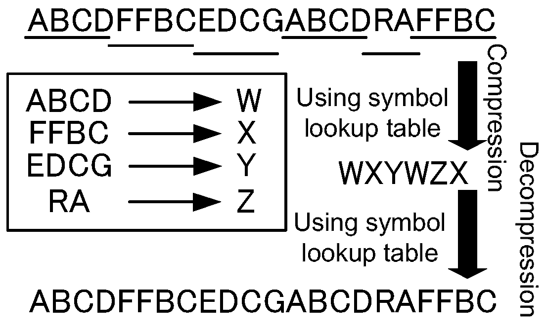
Data compression is mainly performed by replacing frequent data patterns with a compact representation. Algorithms using this replacement approach are called dictionary-based compression. Well-known dictionary data compression algorithms, such as LZW (Lempel-Ziv-Welch) [3,4], perform the steps shown in Figure 1. When a data stream is input into the compressor, it finds the longest frequent patterns and registers those to a symbol lookup table. Here, the unit of the data stream is designated a symbol. In this figure, the symbol translation pattern “ABCD→W” is registered into the symbol lookup table at the beginning. When the pattern is replaced by a symbol that never appears in the stream, the pattern is compressed. Therefore, we use “W” for the compressed symbol for the pattern. While processing the rest of the data stream until the end of the stream, the compressed data stream becomes the compressed one, as shown in the middle of the figure, and then a symbol lookup table is completely generated. The decompressor side decodes the compressed data stream using the lookup table with the same relation between compressed symbol and the original pattern. Therefore, the decompressor needs to receive the lookup table data and translates the compressed data stream to the original one by using it.

Figure 1.
The conventional compression algorithm.
Assume that the data compression algorithm above is applied to a communication data path that needs to send a data stream from one computing platform to another. The compressor must scatter the data stream into several chunks of data. The scattered data is needed to reduce the latency because the lookup table has to be synchronized at every chunk compression. This means that the decompressor must stall in an idle position during the compression process. Because the serialization of the communication degrades the performance, the compression and the decompression must be pipelined based on a fine grain data unit. However, it is impossible to implement the data pipeline due to it being unavoidable to receive the lookup table on the decompressor side. Thus, we need to develop a new compression algorithm without exchanging the table between compressor and decompressor.
2.2. Stream-Based Data Compression on Hardware
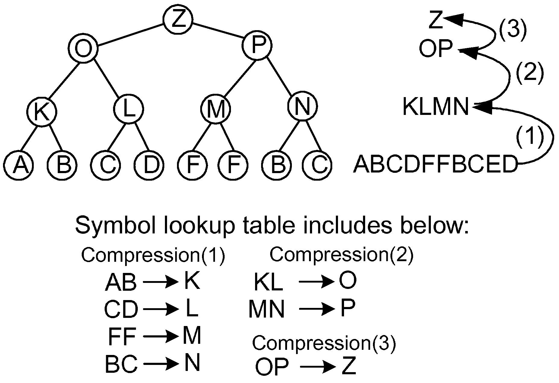
In addition to the problems pointed out before, when we consider the implementation of conventional compression algorithms in hardware, we have two major problems. One is the unpredictable memory usage for the symbol lookup table because the length and the number of frequent patterns depend on the entropy of the input data. The other is the inflexibility of the hardware implementation because the compression operations are atomic regarding the search operations for the longest symbol patterns. In order to overcome these problems, a method called LCA (Lowest Common Ancestor) [7] was adopted for hardware implementation, for which the expression of the input data forms a binary tree as shown in Figure 2. The tree in the figure shows a compression mechanism where each node becomes a compressed symbol of the leaves.
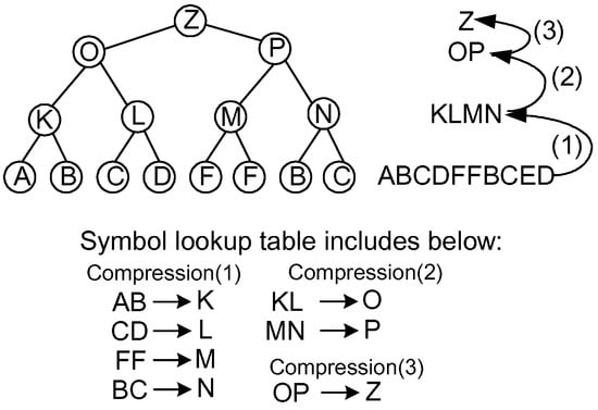
Figure 2.
An example of a succinct data structure using a binary tree.
Inspired by the LCA concept, we have developed a new compression algorithm called LCA-DLT. In the LCA-DLT, a symbol lookup table is prepared for the compression and the decompression. The table has any number N of entries and the i-th entry includes a pair of the original symbols (, ), a compressed symbol , and a frequent counter . The compressor side uses the following rules: (1) reading two symbols (, ) from the input data stream and if the symbols match and in a table entry , after incrementing up the , it outputs as the compressed data; (2) if the symbols do not match any entry in the table, it outputs (, ) and registers an entry where is the index number of the entry; and (3) if all entries in the table are used, all where are decremented until any count(s) become zero and the corresponding entries are deleted from the table.
On the decompressor side, assuming a compressed data S, the steps are the same as the compressor, but the symbol matching is performed based on for each entry. If the compressed symbol matches to in a table entry, it outputs (, ); if not, it reads another symbol from the compressed data stream and outputs a pair of (S, ) and then the pair is registered in the table. When the table entry is full, the same operation is performed as on the compressor side. These operations provide a recoverable histogram on a limited number of lookup table entries.
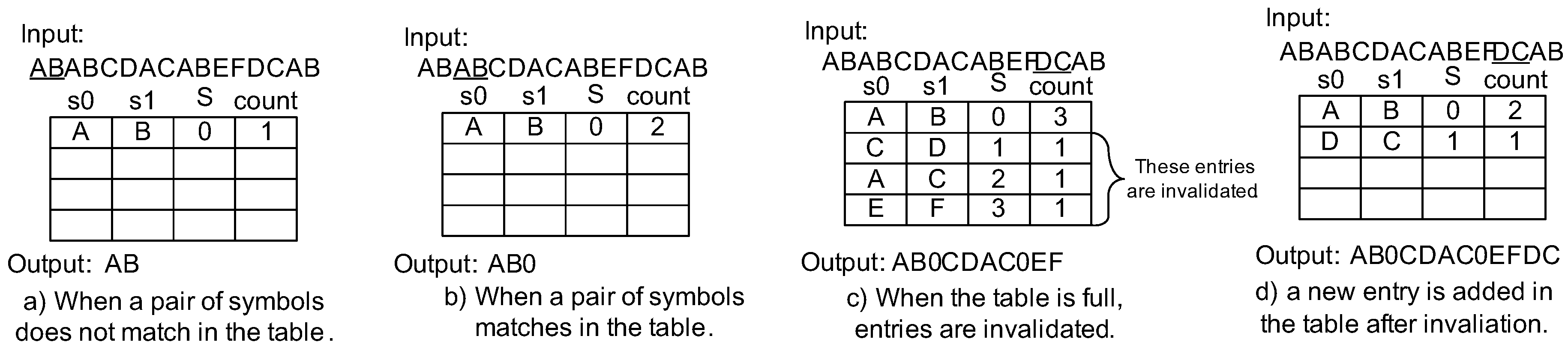
Let us see the example of compression and decompression operations depicted in Figure 3 and Figure 4. Assuming that the input data stream for the compressor is “ABABCDACABEFDCAB”, the compressor first reads the first two symbols “AB” and tries to match them with the table (Figure 3a). However, it fails to match them and registers “A” and “B” as the and in the table. Here, the compressed symbol is assigned in the entry, with index “0”. Thus, a rule AB→0 is made. The is initially set to 1. When the compressor reads a pair of symbols (again “AB”), it finds a match in the table. Figure 3b translates “AB” to “0”. Subsequently the equivalent operations are performed. If the table becomes full (Figure 3c), the compressor decrements (s) of all entries until any s become zero. Here, three entries are invalidated from the table in the figure. The compressor will register a new entry in place of the invalidated entry corresponding to the smallest index of the table. Figure 3d shows that the compressor added a new entry after the invalidation. Finally, the original input data is compressed to “AB0CDAC0EFDC0”.

Figure 3.
Compression example of LCA-DLT.
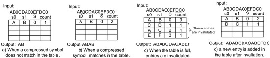
Figure 4.
Decompression example of LCA-DLT.
On the other hand, the decompressor can start working as soon as a symbol is output from the compressor. The decompressor reads the symbol and tries find a match in the table. In Figure 4a, the decompressor reads “A” first. However, it does not match to any compressed symbol in the table (the table is empty). Then, it reads another symbol “B” and registers a new table entry and makes a rule AB→0. The output is “AB”. The decompressor reads the next symbol “0” (Figure 3b). It matches the table entry. Therefore, the decompressor translates it to “AB”. After the subsequent decompression operations, when the table becomes full, the decompressor decrements the (s) in a manner simmilar to the compressor (Figure 3c). The invalidated entries are the same as in the compressor. Therefore, the compressed symbols are consistently translated to the original symbols. Finally, the compressed data is translated by the decompressor and output as “ABABCDACABEFDCAB”, the same as the input data in the compressor.
As we can see in the example, the LCA-DLT performs compression/decompression without exchanging the symbol lookup table. Moreover, those operations are performed without buffering in pipeline manner.
When the compressor supports 8 bit data input, it must support any 8 bit data to compress and translate it to compressed symbols. Here, we need to pay attention to the compressed symbol that must be unused in the input data stream. However, it is impossible to define unused symbols, since any concatenation of eight bits can be input into the compressor. Therefore, the compressor adds the compression mark bit (CMark) that indicates if the symbol is compressed or not. Combining the compressor and the decompressor in a module and cascading the modules as illustrated in Figure 5, we can compress long symbol patterns corresponding to 2, 4, 8 and 16 symbols respectively, when the number of modules increases to four. If the input data at the first compressor is 8 bit long, the output compressed data becomes 12 bits after four modules due to the CMark bits.

Figure 5.
Cascading compressor/decompressor modules.
The LCA-DLT has several good features which support implementations in hardware. It has flexibility for achieving a tradeoff between the compression ratio and the hardware resources required. In terms of the compression speed, the LCA-DLT performs compression and the decompression in pipeline. If the compressed data is represented with a fewer number of bits than the original, the communication data path between the compressor and the decompressor virtually transfers more than the physical peak performance.
However, the compression and the decompression mechanism stop during the invalidation operations according to the algorithm above. This imposes stall cycles in which data is transferred to the decompressor. Even if the compression ratio is good and the compressed data size is significantly smaller than the original, the stall cycles disturb data transfer to the decompressor side. The number of total clock cycles required may become more than the number required for transferring the original data. Thus, the overall performance depends on the stall cycles during the invalidation operations. Moreover, the compression ratio is significantly affected by the invalidation. To achieve the best compression ratio, the smallest probable entries that would not appear in the near future should be deleted. However, the LCA-DLT deletes all the candidate entries. Thus, the compression ratio is affected by the invalidation process mentioned above. If the data flow does not stop during the invalidation, the stall will be eliminated. Moreover, if a part of the invalidation entries is removed, the compression ratio would become higher.
On the other hand, in terms of computing complexity at the compression/decompression, the main overhead is computing cost for table search operations. It costs , where N is the number of entries in the table. Even if the implementation increases the clock speed, it is an unavoidable computing cost. Therefore, it is necessary to improve the algorithm decreasing the cost up to , where C is a constant delay. Therefore, in this paper, we consider a lazy compression method that does not stop the data flow. In order to easily understand the explanation in the following sections, we call the algorithm presented before the full search method because it deletes all the candidate table entries at invalidation.
3. Related Works
Data compression algorithms have been investigated in the last three decades. The recent advanced research applies an encryption mechanism that embeds additional information into image data and implements a lossless compression/decompression mechanism [8,9]. The most important lossless compression algorithm is LZW, which is simple and effective. An optimized LZW algorithm is used, for example, in Linux kernel compression, and is used for speed up of the compression operation. We can also find in the market gz, bzip2, rar, lzh and so on for lossless compression. However, when we try to implement a compressor into hardware, we inevitably face the problems referred to before. The important research on data compression is how to manage the symbol lookup table in a limited memory space. In the machine learning field, we can find well-known algorithms, such as the lossy counting [10]. The algorithm creates a histogram in a limited number of entries using a linear list data structure and counts the frequency of data patterns. The space saving [11] improves the memory usage of the lossy counting. However, these algorithms use operations based on pointers and are implemented in software. For the data stream of k different symbols, an attractive algorithm for frequency counting has been proposed where the top- frequent items are exactly counted within space [12] for any constant . However, this also provides a software solution.
The main compression task performed in LZ77 and LZ78 is to compute the longest matches between the registered patterns in the lookup table and the data to be processed. It returns indices of the lookup table. The indices are used in the decompression task by the opposite lookup operations. The decompression task can be quickly processed because the lookup operations simply perform integer indexing for data array of the table. The speed does not depend on the size of dictionary. However, the longest match during the compression needs associate memory (i.e., hash memory). To improve the compression ratio, the associate memory needs to be managed in a dynamic way. This is not scalable in terms of memory size and also becomes a disadvantage to increasing the size of the sliding dictionary that is the typical advantage of the LZ algorithm to increase the compression ratio. For example, gzip allocates several Kbytes for the sliding memory. However, in order to implement compact hardware, it is hard to prepare such a memory size in Kbyte order. For example, several previous research results such as Ref. [13,14] solved the problem regarding the longest matching by parallelizing the operations. However, it is not possible to extend the size of the sliding dictionary because the number of start indices increases related to the length of the symbols. The technique in the research limits the memory size to 32 symbols. However, our approach uses a byte-pair encoding technique that compresses a symbol pair into a single symbol. Although it limits the compression availability by the fixed-to-fixed encoding, it addresses the memory resource problem and is available to be implemented on a small amount of hardware resource that guarantees treating a large amount of data streams based on the grammar compression with universal coding. Our technique uses a symbol pair as the key in the associate memory. Therefore, the longest matching operation is simply performed without the memory size limitation for a lookup table. Moreover, in the aspect of performance, the conventional compression methods based on lookup table are not considered to achieve stable throughput due to the eager management of the table. Our lazy approach will achieve stable I/O performance during compression/decompression by skipping the lookup operations, and the lazy mechanism also maintains consistency of compressed data among encoding and decoding operations.
In addition to the lookup table approaches in the previous research, various hardware implementations of lossless data compression techniques have been investigated in this decade. A well-known approach is arithmetic coding (here in short, AC) [15] that widely compresses multimedia data such as JPEG2000 and H.264 video coding [16,17,18,19]. Hardware implementations are proposed such as [20,21] to accelerate the computing speed. The implementations proposed state-of-the-art techniques for performance improvements. However, those never guarantee I/O throughput of the compression/decompression module because those inevitably need a lookup table mechanism to decide the value domains and must decide the encoded values from the original data symbols without lazily suspending or skipping the compression operations. In this paper, the lazy compression technique will guarantee the I/O throughput with skipping the lookup table operations. The performance capability of I/O helps a high-speed communication path that can not stall the I/O cycles such as transferring sensor data for machinery application without buffering memory.
Various lossless compression methods mainly targeted to hardware implementation have also been investigated in the field of processor architecture. Researchers focused on performance improvements of memory I/O using data compression methods, focusing on virtually increasing I/O bandwidth and size of space. This approach has improved program execution performance on the processor. Initially, they looked into the main memory using the software LZ-based compression method [22]. Similarly, IBM (North Castle Armonk, NY, USA) has released a memory system called MXT [23], based on hardware implementation using the adaptive LZ-based compression. It reduces the memory usage than the actual data size. However, the recent research trend shifts to the cache memory level (mainly, data transfers between L1 and L2 caches). For example, the FPC [24] compresses the cache line using a fixed lookup table that specifies rules to replace the original data to encoded patterns. The compression mechanism works based on a data word. Therefore, it does not consider the frequency among cache lines. The BDI [25] improves the FPC’s approach, adopting multiple base data values at the compression for a cache line. The base values help to reduce the number of bits of compressed data due to reducing the one of offset (delta) values. It provided a better compression ratio than the FPC. Although these techniques were targeted to full hardware implementation, the compression target was the intermediate data that were produced or consumed by running a program on the processor. Therefore, most data patterns include zeros in the cache line. Thus, previous research does not consider the frequency among multiple cache lines, and the algorithms also do not fit to the normal data such as multimedia data. On the other hand, the C-Pack [26] improved the performance of the compression rate better than the one of the BDI. It combines the approach of the FPC and a lookup table mechanism. The lookup table is created dynamically. However it must specify a fixed number of cache lines to be compressed because the physical size of the lookup table buffer does not grow dynamically. Therefore, it never enabled handling the data stream. Additionally the AC-based approach was also investigated. The [27] performs Huffman encoding in cache memory hardware. It achieves a good compression ratio. However, it does not improve the program execution much due to inevitably increasing the number of cycles to encode/decode the Huffman codewords. On the other hand, the lazy management approach proposed in this paper provides a promised I/O throughput at the compression/decompression.
Regarding the lazy compression algorithm, recently Google’s (Mountain View, CA, USA) snappy is a typical algorithm that skips compression operation if the compressing data pattern is not registered in the symbol lookup table (in snappy, it is actually implemented by a linear list). The snappy achieves variable compression speed between 30 MB/s and 250 MB/s. The algorithm is hard to implement in hardware. Therefore, the speed achieved depends on the CPU processing power.
Comparing the conventional and the latest compression algorithms with the LCA-DLT, if the lazy compression mechanism is equipped in the LCA-DLT algorithm data transfer, throughput is directly related to the compression ratio. Therefore, the throughput does not depend on the input data pattern (i.e., data’s entropy of the input data). Finally, we can realize a new compression mechanism that provides scalable compression.
4. Dynamic Histogram Management in Stream-Based Lossless Data Compression
We propose two new techniques called dynamic invalidation and lazy compression, and then we combine those to the full search LCA-DLT algorithm. The former technique extends the probability to find unused entries in the lookup table and improve the compression ratio. The latter one is an optimization technique for dynamic invalidation to eliminate stalls during the invalidate operation in the lookup table to find insert points at new symbol pair registration. Let us explain those techniques.
4.1. Dynamic Invalidation for Symbol Lookup Table Management
With dynamic invalidation for a symbol lookup table management technique, we prepare a remove pointer and an insertion pointer. Initially, the remove pointer points to any entry of the symbol lookup table. The is decremented when the pointer comes to the table index i. If the becomes zero after the decrement, the entry is removed from the table. The pointer is moved to the next table index after any table search operation. On the other hand, the insertion pointer initially points also to any empty entry in the symbol lookup table. If the entry is used, the pointer moves to an unused entry. If the table is fully used, the pointer points any entry, and then if an entry is removed, the pointer points to the empty entry. Using these two pointers, we can expect that the entries occupied in the symbol lookup table are moderately removed. This means that the future possibility for symbol appearance is kept in the table, and then better compression ratio is expected.
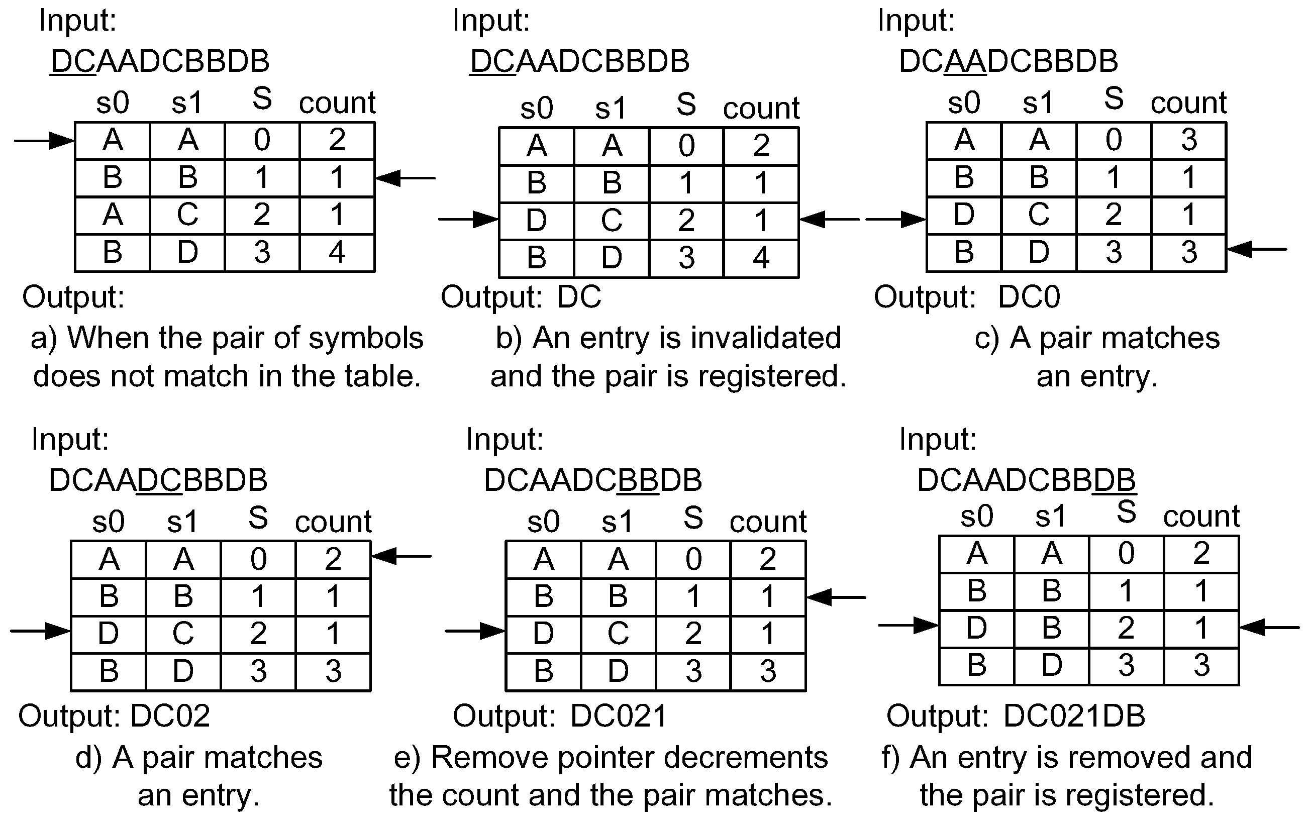
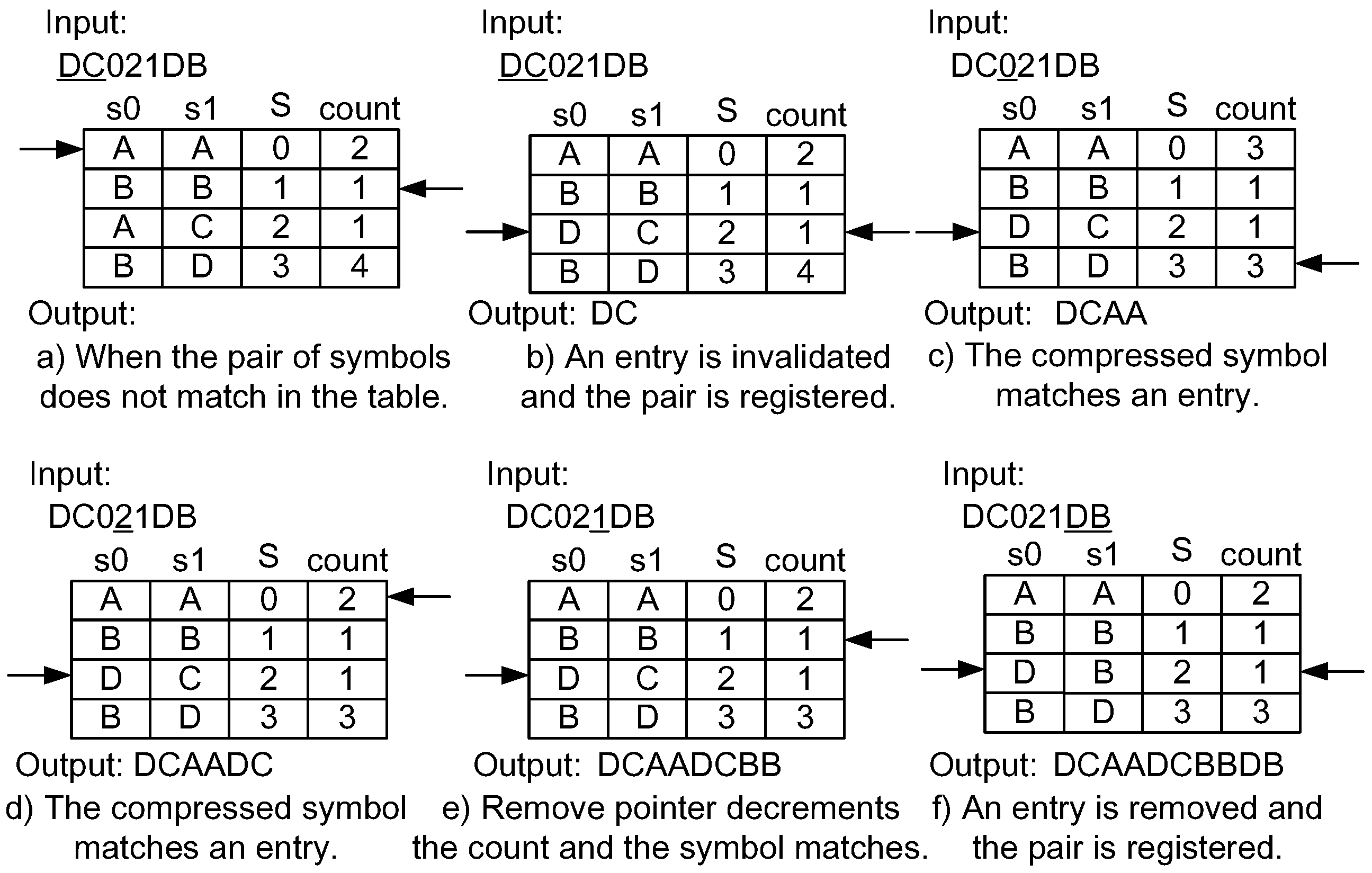
Figure 6 shows an example of the application of invalidation mechanism for compression. We assume that “DCAADCBBDB” is input into the compressor and the remove pointer starts on the second entry of the table. First, ”DC” does not match any entry in the table (Figure 6a). The compressor waits until any empty entry appears. The remove pointer is moved to the next entry and the count value is decremented. In Figure 6b, the count value of the third entry becomes zero, and then the entry is removed. The insertion pointer is moved to point to the empty entry. The new entry for “DC” is registered to where the insertion pointer is pointing. Now, the “DC” is output. During these operations, the input and the output of the compressor stall. When the input symbol pair matches an entry, it is compressed, as shown in Figure 6c,d, that the remove pointer is moved and the count value is decremented. If the entry that matches the input symbol pair corresponds to the one pointed out by the remove pointer, the count value does not change, as shown in Figure 6e. Finally, after the initially inserted “DC” is removed due to the count value, the entry is used as a new one. Because it was not found in the table, “DB” is output. Thus, the compressed data stream becomes “DC012DB”.
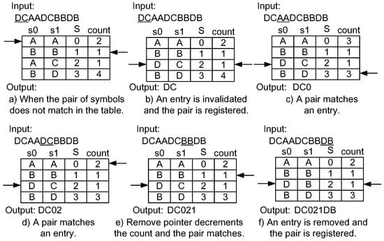
Figure 6.
Example of a compression mechanism using the dynamic invalidation.
Figure 7 shows the steps of the decompression mechanism using dynamic invalidation. The input compressed data stream is the one generated by the compression in Figure 6. The insertion and the remove pointers begin from the same entries where the compressor is initially defined. Although the target is the compressed data, the steps are equivalent to the ones performed on the compressor side. In Figure 7a,b, the I/O of the decompressor stall. When matching the compressed symbol in an entry, the decompressor outputs the corresponding symbol pair such as Figure 7c,d. Again, a stall occurs during the invalidation of an entry as shown in Figure 7e,f. Finally, the original data stream is decoded.

Figure 7.
Example of a decompression mechanism using the dynamic invalidation.
According to the compression and the decompression examples explained above, the dynamic invalidation provides moderate deletion of unused entries by decrementing the count values one after the other. As long as possible, if we keep the table entries fully occupied, the compression ratio is expected to become better than the full search method because the probability for matching entries becomes higher than the one of the full search.
4.2. Lazy Compression
Another optimization technique is the lazy compression. This technique ignores compression using the symbol lookup table when the symbol lookup table is full. During the invalidation and the registration of an entry in the table, the compressor passes through the input data symbols to the output. Therefore, the lazy compression technique never stalls and continuously outputs the data to the decompressor side. However, the compression ratio will become worse due to the pass-through operation without any compression effort.
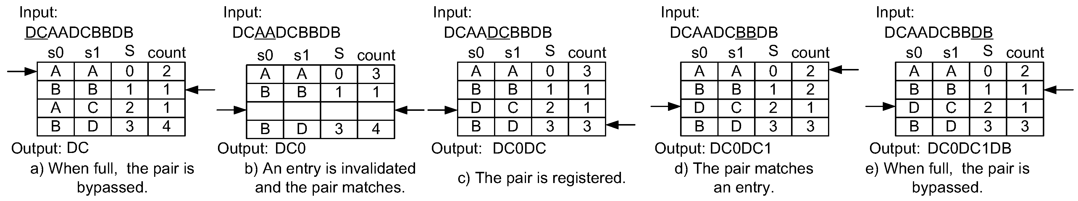
Figure 8 shows the compression example of the lazy compression technique applied to the LCA-DLT with the dynamic invalidation. The input data stream is the same as in the example of the dynamic invalidation. First, the “DC” does not match any entry in the table. Here, the lazy compression just passes through the symbol pair without registering the pair into the table. Therefore, no stalling occurs such as in Figure 8a,e. When the symbol pair matches an entry, it compresses the pair to the corresponding symbol as shown in Figure 8b,d. If there exist empty entry(ies) in the table when the input symbol pair does not match any entry, it is registered to the empty entry and is also passed through to the output like Figure 8c. The output from the compressor becomes “DC0DC1DB”, which is larger in size than “DC021DB” in the case of eager compression.
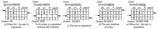
Figure 8.
Example of a compression mechanism using the lazy compression technique.
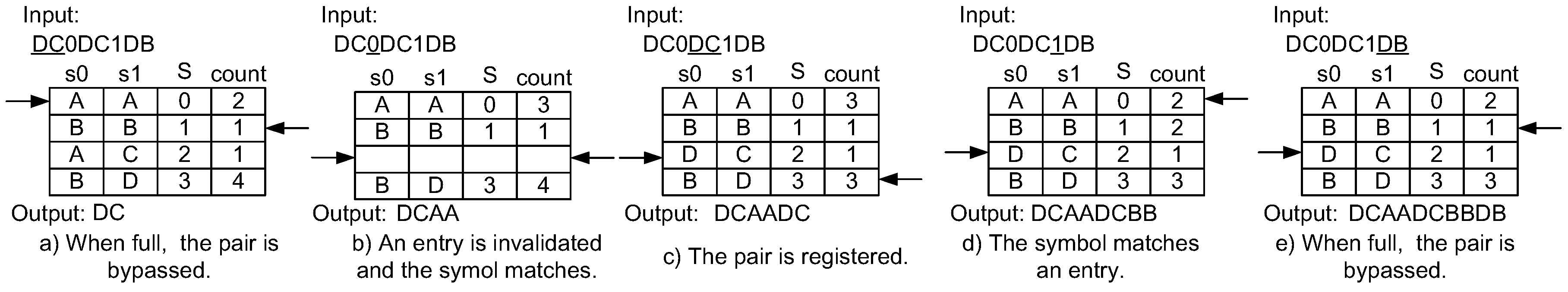
The decompression works in a manner simmilar to the compression, as illustrated in Figure 9. First, “D” is not included in the domain of the indices of the table. It means that the input is the original data pair, and, since the CMark bit is actually added to the compressed data, it is easy to know if the data is in the domain of the indices. The compressor does not register the pair and passes through “DC” to the output as shown in Figure 9a,e without any stall. If the compressed data is in the domain of the table, the decompressor translates the original symbol pair such as in Figure 9b,d. When the symbol is not included in the domain of the indices of the table, and if empty entry(ies) exist, the input symbol pair is registered.
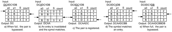
Figure 9.
Example of a decompression mechanism using the lazy compression technique.
Thus, the lazy compression does not stall at all, but the compression ratio becomes worse. Therefore, it is suitable for a communication data path that does not allow the data flow to stop. As we can see in the compression and the decompression examples applying the lazy compression technique, the compressor and the decompressor never stop the data flow. The bypass mechanism keeps the data bandwidth promised in the compressor input interface. If the compression ratio is good, the communication data path achieves higher throughput than the physical medium. However, we need to evaluate the effect of the bypass operation during the table invalidation operations.
4.3. Implementation
The implementation of the dynamic invalidation needs a set of round-robin decrement logic for managing the remove pointer. Both the compressor and the decompressor have similar logic. The lazy compression just needs to introduce the bypass connection to the output without registering the entry to the table.
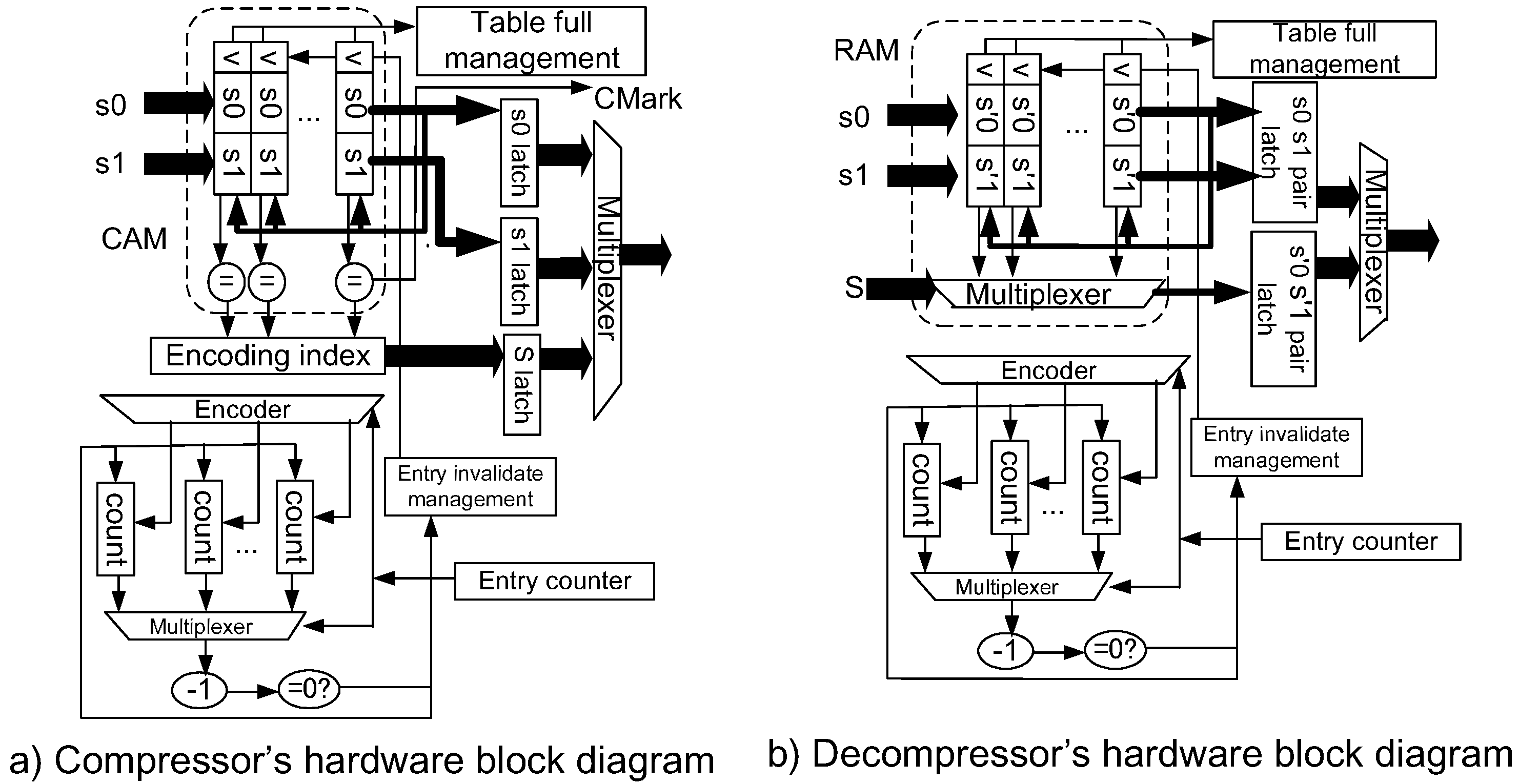
Figure 10a shows the organization of the compressor. The symbol pair matching logic is implemented by a CAM (content addressable memory). However, when we target implementations using FPGA (Field Programmable Gate Array), we inevitably need to implement the CAM logic by registering latches. Therefore, the total size of the logic becomes larger. For the counter logic management, we can apply the counters to the block RAM in the FPGA, and thus less hardware is required. The decompressor is depicted in Figure 10b. The symbol lookup is performed by simply reading the data in a RAM. When the RAM is implemented on the block RAM macro of an FPGA, less hardware is required to implement the decompressor.
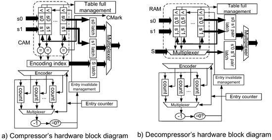
Figure 10.
Implementation of LCA-DLT with the dynamic invalidation.
Dynamic invalidation and the lazy compression techniques are powerful solutions, which are expected to improve the compression ratio and to achieve higher throughput, without stalling the data pipeline, than the full search method. Due to the simple implementations of the compressor and the decompressor, the LCA-DLT works as a very compact and useful hardware-based lossless compression accelerator to improve the efficiency of the communication data path effectively.
5. Performance Evaluation
Let us evaluate the static and dynamic performances of LCA-DLT applying the dynamic invalidation and the lazy compression. The static one will provide the compression ratios using a software emulator. The dynamic one shows the performance of real hardware implementation. We compare the performance with the one of the full search version. Although the LCA-DLT handles a continuous data stream, in order to evaluate a quantitative situation, we used several patterns of 10 Mbyte benchmark data (for transferring at eight bits without compression takes 10,485,760 clock cycles) of the text collection listed in [28]: Linux source code, MIDI pitch values, protein sequences, gene DNA sequences, English texts and XML.
5.1. Effect on the Compression Ratio
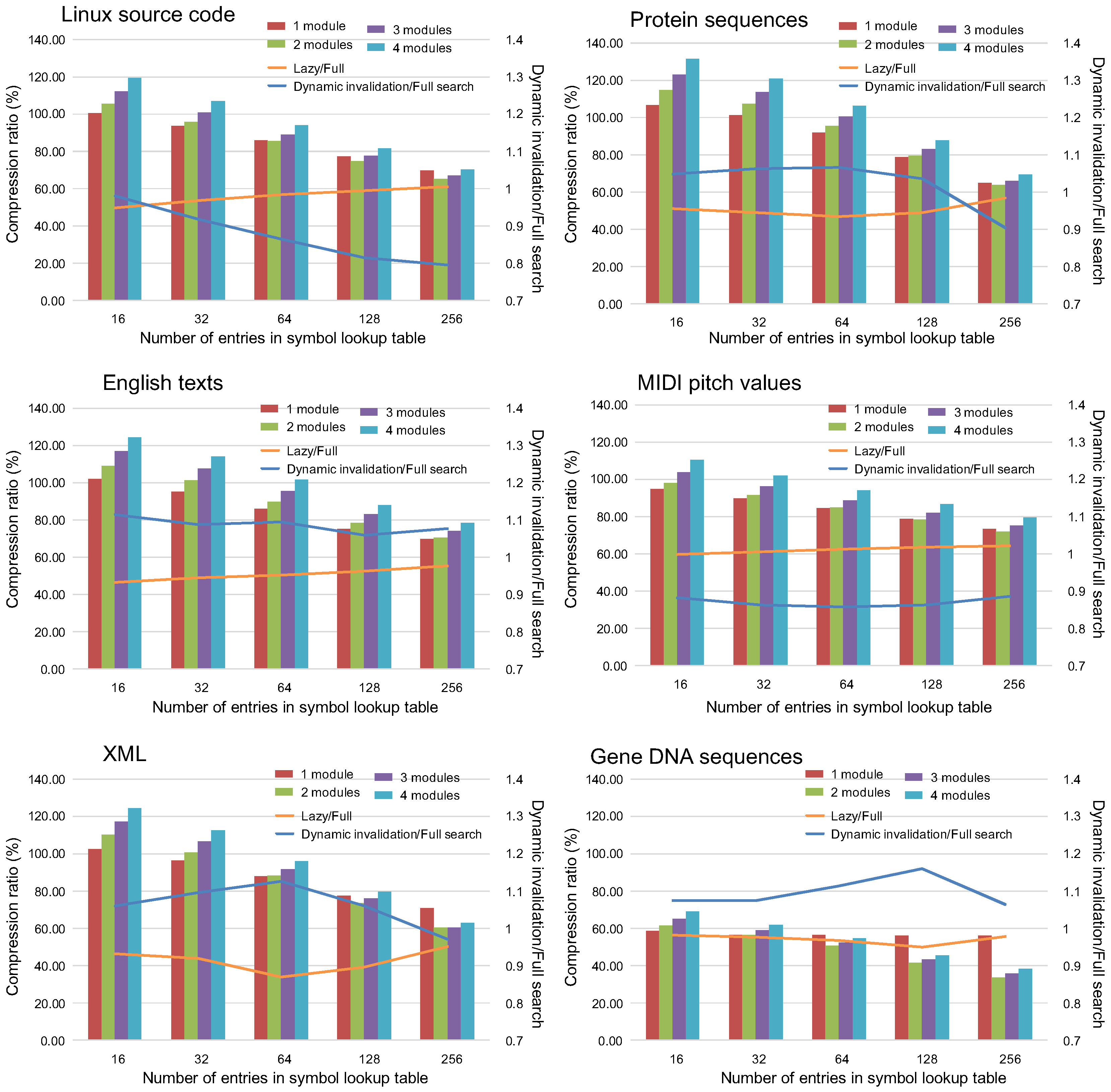
Graphs in Figure 11 show the compression ratios when the dynamic invalidation and the lazy compression mechanism are applied to the LCA-DLT. the bars shown are the compression ratio defined as the compressed data sizes divided by the size of the original data. Additionally, the ratios where the compressed data size with the lazy compression technique are divided by the full search method are shown as the orange lines. Similarly, the ones where the data sizes with the dynamic invalidation method divided by the full search one are depicted in the blue lines. The compressor with four LCA-DLT modules is applied to the experiments for the results depicted as the lines. When the ratios lines are less than 1, it means that the proposed method is effective against the full search method.
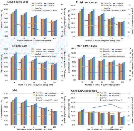
Figure 11.
Compression ratios of LCA-DLT with the dynamic invalidation and with the full search method.
Regarding the compression ratios when both of the proposed techniques are applied, the ratios become better as the number of table entries increases. Although the lazy compression ignores the input symbol pair if it fails to match to any entry, the data compression is effectively applied to the data.
Focusing on the orange lines in the graphs, almost all results show better performance than the full search method. Therefore, we confirmed that the lazy compression does not disturb the compression, although it does not compress the input data when the data pair does not match entries of the symbol lookup table.
The dynamic invalidation disturbs the compression, resulting in both better and worse compression ratios than the full search method, although we were expecting that the moderate invalidation for the table entries always brings better performance. We found that the dynamic invalidation technique works in the cases when the entropy of the input data stream is high. For example, the case of DNA shows bad compression performance because the number of combinations of the existing data patters in the data stream is only 16. However, in worse cases, the degradations observed from the graphs are less than 10%. Therefore, we can conclude that the dynamic invalidation produces reasonable results if we consider the hardware performance that we will see in the next evaluation.
In total, both of the proposed mechanisms provide more effective compression ratios than the full search method. Those mechanisms work well if the randomness of the data is high (i.e., the data entropy is high).
5.2. Dynamic Hardware Performance
We have measured the stall clock cycles to compare the dynamic performance of hardware implementation with the proposed techniques. We used the Xilinx (San Jose, CA, USA) Artix7 FPGA XC7A200T-1FBG676C. The full search method works at 100 MHz in this device [6]. On the other hand, the implementation with both proposed mechanisms works at 130 MHz because the implementation was simplified by the lazy management of the symbol lookup table.
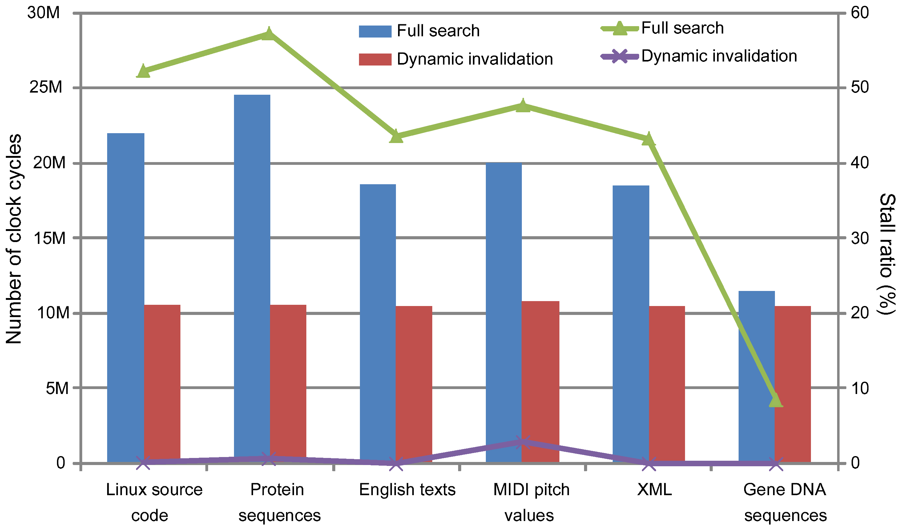
Figure 12 shows the stall cycles in the bars and the stall ratios against the total clock cycles in the lines when we applied the dynamic invalidation and the full search techniques, respectively. The graph shows that the dynamic invalidation mechanism is fully effective in reducing the number of stall cycles. Therefore, even when the compression ratio is not better than the full search method, as we have seen in the previous evaluation regarding the compression ratio, the total throughput of the data stream becomes much better than the full search method. The degradation of the throughput is about 30% in the case of the full search. However, it is less than 3% in the case of the dynamic invalidation.
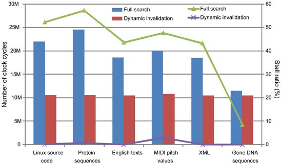
Figure 12.
Stall cycles and the ratios of LCA-DLT with/without the dynamic invalidation and the lazy compression mechanism.
Regarding the lazy compression, we did not show the stall ratios in the graph because there is no stall cycle at all. This means that the compression delay is the number of clock cycles for input data streams. The number of clock cycles is equal to the number of bytes of the input data (i.e., 10 M cycles) because the experiments here use an eight-bit data width of the first LCA-DLT compression module. Finally, we combine the lazy compression with the dynamic invalidation, and thus the LCA-DLT is improved to provide a better compression ratio and the fastest compression speed.
5.3. Application Example Using Image Data
Finally, we have performed an application example using image data. Recently, lossless compression has been focused on medical applications [29,30] due to increasing resolution of sensing technologies such as 10 T fMRI. In the publishing industry, image quality and printing speed is quickly increasing due to improving mechanical control. Here, we show a result obtained by compressing a CMYK image data with LCA-DLT with dynamic invalidation and lazy compression. We applied an image data N1 from the CMYK standard color image data of ISO 12640: 1997 with a single compression module of LCA-DLT. The number of original data bits of each CMYK image is 41,998,144. Table 1 shows the number of bits after compression and its compression ratio of the experimental evaluation based on the hardware implementation.

Table 1.
Compression performance for applying CMYK image data.
First, we have input each piece of image data of CMYK to the compression module directly (called direct) in Table 1. Although the K element of the image was compressed to 76%, others were reduced by only less than 10%. Before the compression, we have preprocessed the original data with a diff operation between pixels. The diff pixel data was calculated by , where . The result is shown as diff in Table 1. The compression ratio was improved up to 15% in any of the CMYK data. As shown in this application example, to utilize the LCA-DLT performance efficiently, preprocessing the original data is needed before input. It depends on the data type. In the case of the image data, the entropy was controlled before the input. It is simple to implement the diff algorithm above into the hardware, and it improved the compression ratio.
6. Conclusions
This paper proposed two new mechanisms for lossless compression targeting hardware experimental implementations. We proposed the dynamic lazy mechanisms and applied them to the LCA-DLT. According to the evaluation, the revised LCA-DLT works perfectly in the aspects of the compression and the performance. In the future, we will apply the hardware compressor and decompressor to quick communication data paths in order to evaluate the effective performance of the compressor.
Acknowledgments
We would like to thank Leonel Sousa at INESC-ID, Lisbon, Portugal for proofreading this paper in the review process. This work was partially supported by JSPS KAKENHI Grant Number 15H02674, 26280088 and JST CREST.
Author Contributions
Koichi Marumo and Shinichi Yamagiwa have written the paper, and provided the main ideas and implementation details on the hardware as well as in the algorithm; Ryota Morita has designed the experiments for the compression ratios using the benchmark data sets; and Hiroshi Sakamoto has contributed with the fundamental theory of the compression. All authors have read and approved the final manuscript.
Conflicts of Interest
The authors declare no conflict of interest.
References
- Yamagiwa, S.; Aoki, K.; Wada, K. Performance Enhancement of Inter-Cluster Communication with Software-based Data Compression in Link Layer. In Proceedings of the International Conference on Parallel and Distributed Computing Systems (PDCS 2005), Phoenix, AZ, USA, 14–16 November 2005; pp. 325–332.
- Vitter, J.S. Design and Analysis of Dynamic Huffman Codes. J. ACM 1987, 34, 825–845. [Google Scholar] [CrossRef]
- Ziv, J.; Lempel, A. A universal algorithm for sequential data compression. IEEE Trans. Inf. Theory 1977, 23, 337–343. [Google Scholar] [CrossRef]
- Ziv, J.; Lempel, A. Compression of individual sequences via variable-rate coding. IEEE Trans. Inf. Theory 1978, 24, 530–536. [Google Scholar] [CrossRef]
- Leavlin, E.J.; Singh, D.A.A.G. Hardware Implementation of LZMA Data Compression Algorithm. Int. J. Appl. Inf. Syst. 2013, 5, 51–56. [Google Scholar]
- Yamagiwa, S.; Marumo, K.; Sakamoto, H. Stream-based Lossless Data Compression Hardware using Adaptive Frequency Table Management. In Big Data Benchmarks, Performance Optimization, and Emerging Hardware; Lecture Note in Computer Science; Springer: Berlin/Heidelberg, Germany, 2015. [Google Scholar]
- Maruyama, S.; Sakamoto, H.; Takeda, M. An Online Algorithm for Lightweight Grammar-Based Compression. Algorithms 2012, 5, 214–235. [Google Scholar] [CrossRef]
- Qin, C.; Chang, C.C.; Chiu, Y.P. A Novel Joint Data-Hiding and Compression Scheme Based on SMVQ and Image Inpainting. IEEE Trans. Image Process. 2014, 23, 969–978. [Google Scholar]
- Qin, C.; Chang, C.C.; Chen, Y.C. Efficient reversible data hiding for VQ-compressed images based on index mapping mechanism. Signal Process. 2013, 93, 2687–2695. [Google Scholar] [CrossRef]
- Manku, G.S.; Motwani, R. Approximate Frequency Counts over Data Streams. In Proceedings of the 28th International Conference on Very Large Data Bases, Hong Kong, China, 20–23 August 2002; pp. 346–357.
- Metwally, A.; Agrawal, D.; Abbadi, A.E. An Integrated Efficient Solution for Computing Frequent and Top-k Elements in Data Streams. ACM Trans. Database Syst. 2006, 31, 1095–1133. [Google Scholar] [CrossRef]
- Karp, R.M.; Shenker, S.; Papadimitriou, C.H. A Simple Algorithm for Finding Frequent Elements in Streams and Bags. ACM Trans. Database Syst. 2003, 28, 51–55. [Google Scholar] [CrossRef]
- Fowers, J.; Kim, J.-Y.; Burger, D.; Hauck, S. A Scalable High-Bandwidth Architecture for Lossless Compression on FPGAs. In Proceedings of the 23rd IEEE International Symposium on Field-Programmable Custom Computing Machines, Vancouver, BC, Canada, 2–6 May 2015.
- Kim, J.Y.; Hauck, S.; Burger, D. A Scalable Multi-engine Xpress9 Compressor with Asynchronous Data Transfer. In Proceedings of the IEEE 22nd Annual International Symposium on Field-Programmable Custom Computing Machines (FCCM), Boston, MA, USA, 11–13 May 2014; pp. 161–164.
- Langdon, G.; Rissanen, J. Compression of Black-White Images with Arithmetic Coding. IEEE Trans. Commun. 1981, 29, 858–867. [Google Scholar] [CrossRef]
- Schwarz, H.; Marpe, D.; Wiegand, T. Overview of the Scalable Video Coding Extension of the H.264/AVC Standard. IEEE Trans. Circuits Syst. Video Technol. 2007, 17, 1103–1120. [Google Scholar] [CrossRef]
- Osorio, R.R.; Bruguera, J.D. Arithmetic coding architecture for H.264/AVC CABAC compression system. In Proceedings of the Euromicro Symposium on Digital System Design (DSD 2004), Rennes, France, 31 August–3 September 2004; pp. 62–69.
- Chuang, T.D.; Chen, Y.J.; Chen, Y.H.; Chien, S.Y.; Chen, L.G. Architecture Design of Fine Grain Quality Scalable Encoder with CABAC for H.264/AVC Scalable Extension. J. Signal Process. Syst. 2010, 60, 363–375. [Google Scholar] [CrossRef]
- Lo, C.C.; Tsai, S.T.; Shieh, M.D. Reconfigurable architecture for entropy decoding and inverse transform in H.264. IEEE Trans. Consum. Electron. 2010, 56, 1670–1676. [Google Scholar] [CrossRef]
- Pande, A.; Zambreno, J.; Mohapatra, P. Hardware Architecture for Simultaneous Arithmetic Coding and Encryption. In Proceedings of the International Conference on Engineering of Reconfigurable Systems and Algorithms (ERSA), Las Vegas, NV, USA, 18–21 July 2011.
- Mitchell, J.L.; Pennebaker, W.B. Optimal hardware and software arithmetic coding procedures for the Q-Coder. IBM J. Res. Dev. 1988, 32, 727–736. [Google Scholar] [CrossRef]
- Zukowski, M.; Heman, S.; Nes, N.; Boncz, P. Super-Scalar RAM-CPU Cache Compression. In Proceedings of the 22nd International Conference on Data Engineering, Atlanta, GA, USA, 3–8 April 2006; p. 59.
- Tremaine, R.B.; Franaszek, P.A.; Robinson, J.T.; Schulz, C.O.; Smith, T.B.; Wazlowski, M.; Bland, P.M. IBM Memory Expansion Technology (MXT). IBM J. Res. Dev. 2001, 45, 271–285. [Google Scholar] [CrossRef]
- Alameldeen, A.R.; Wood, D.A. Adaptive Cache Compression for High-Performance Processors. In Proceedings of the 31st Annual International Symposium on Computer Architecture, München, Germany, 19–23 June 2004; p. 212.
- Pekhimenko, G.; Seshadri, V.; Mutlu, O.; Gibbons, P.B.; Kozuch, M.A.; Mowry, T.C. Base-delta-immediate Compression: Practical Data Compression for On-chip Caches. In Proceedings of the 21st International Conference on Parallel Architectures and Compilation Techniques, Minneapolis, MN, USA, 19–23 September 2012; pp. 377–388.
- Chen, X.; Yang, L.; Dick, R.P.; Shang, L.; Lekatsas, H. C-Pack: A High-Performance Microprocessor Cache Compression Algorithm. IEEE Trans. Very Large Scale Integr. Syst. 2010, 18, 1196–1208. [Google Scholar] [CrossRef]
- Arelakis, A.; Stenstrom, P. SC2: A Statistical Compression Cache Scheme. In Proceeding of the 41st Annual International Symposium on Computer Architecuture, Minneapolis, MN, USA, 14–18 June 2014; pp. 145–156.
- The Prologue. Available online: http://pizzachili.dcc.uchile.cl/ (accessed on 30 September 2016).
- Sanchez, V.; Nasiopoulos, P.; Abugharbieh, R. Efficient Lossless Compression of 4-D Medical Images Based on the Advanced Video Coding Scheme. IEEE Trans. Inf. Technol. Biomed. 2008, 12, 442–446. [Google Scholar] [CrossRef] [PubMed]
- Wu, D.; Tan, D.M.; Baird, M.; DeCampo, J.; White, C.; Wu, H.R. Perceptually lossless medical image coding. IEEE Trans. Med. Imaging 2006, 25, 335–344. [Google Scholar] [CrossRef] [PubMed]


© 2016 by the authors; licensee MDPI, Basel, Switzerland. This article is an open access article distributed under the terms and conditions of the Creative Commons Attribution (CC-BY) license (http://creativecommons.org/licenses/by/4.0/).