An RTT-Aware Virtual Machine Placement Method

Abstract
:1. Introduction
2. Related Works
3. Dynamic VM Placement
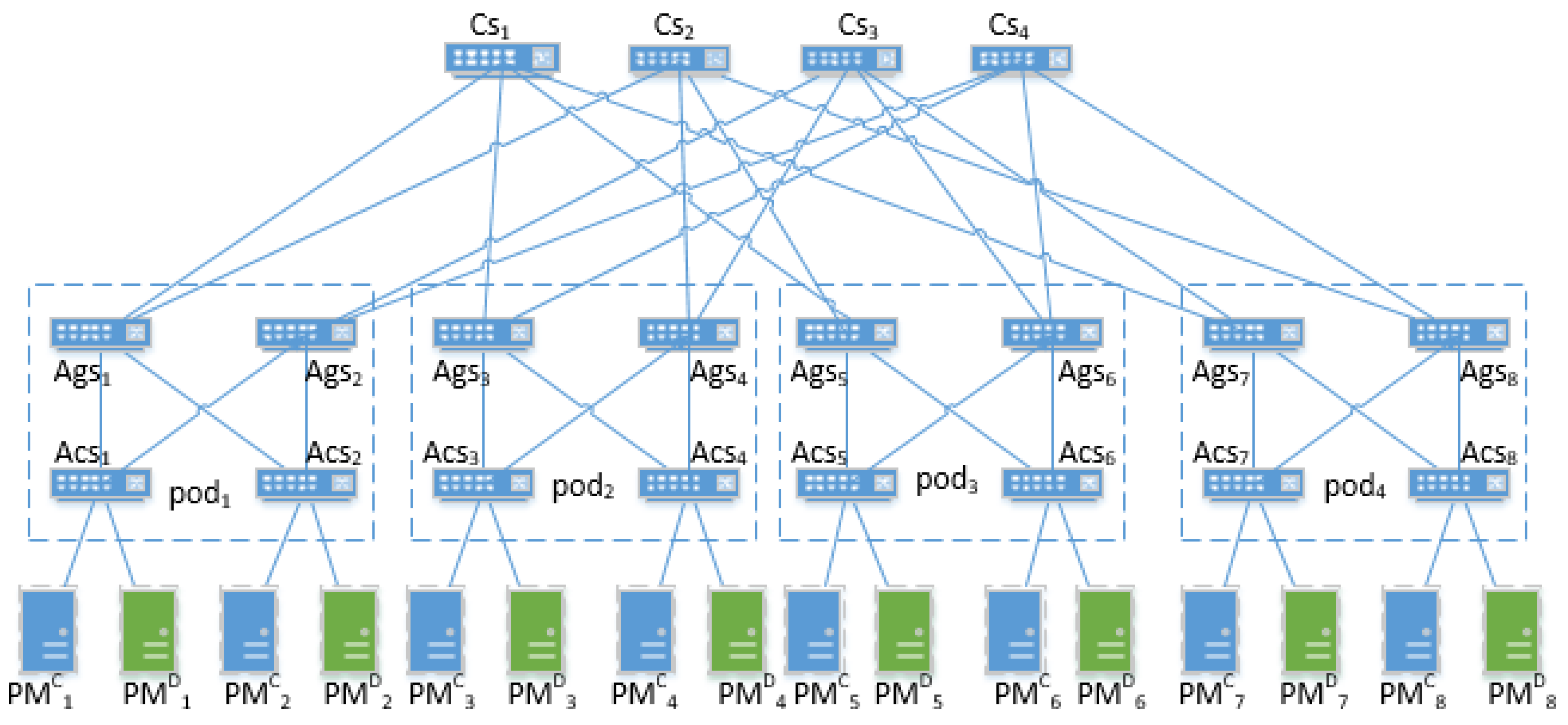
3.1. Proposed Architecture
- User Request: we suppose that smart devices exploit cloud resources by request-response. Smart devices’ requests require the cloud center to deploy VMs for providing appropriate service.
- Load Balancer: the load balancer could redirect the incoming requests to candidate switches according to the number of requests.
- Physical Machine: physical machines are an important part of the cloud, which provide a runtime environment for virtual machines. The physical machines are connected by fat-tree network structure.
- Dynamic Allocation of VM: this part runs the scheduling algorithms that allocate the VM dynamically for different requests to minimize the average RTT.
3.2. Problem Formulation
4. Algorithms
| Algorithm 1 RTT-Aware VM placement algorithm (RTTVMPA) |
| 1. Begin |
| 2. Initial = 0, = 0, , |
| 3. Get list of s as |
| 4. Get list of s as |
| 5. Get the RTT Matrix and |
| 6. For each core switch () do: step:7—22 |
| 7. For each in do: do: step:8 |
| 8. Sort in ascending order by |
| 9. For each in do: do: step:10 |
| 10. Sort in ascending order by |
| 11. Get requests set belonging to |
| 12. Get the number of requests in , , |
| 13. For each request in do: step:14–22 |
| 14. Get the th in |
| 15. Get the th in |
| 16. |
| 17. If is , |
| 18. If is , |
| 19. |
| 20. If is , |
| 21. If is , |
| 22. Calculate according to Equation (9) |
| 23. Calculate the according to Equation (10) |
| Algorithm 2 VM sharing algorithm (VMSA) |
| Input: , |
| Out: |
| 1. |
| 2. If is on , then get state < , , > |
| 3. If |
| 4. |
| 5. Share current |
| 6. |
| 7. End if |
| 8. End if |
| Algorithm 3 VM establishing algorithm (VMEA) |
| Input: , |
| Out: |
| 1. |
| 2. If according to Equation (1) or Equation (2) |
| 3. Establish on current and set state < , , > |
| 4. |
| 5. |
| 6. End if |
| Algorithm 4 VM rescheduling algorithm (VMRA) |
| Input: and s that serve the requests connected to the abnormal core switch previous |
| 1 For each , in , s |
| 2. Get requests set that served by and that served by |
| 3. Get the index of l to satisfy |
| 4. Get the index of m to satisfy |
| 5. Reschedule the to |
| 6. Reschedule the to |
| 7. End for |
5. Experiments
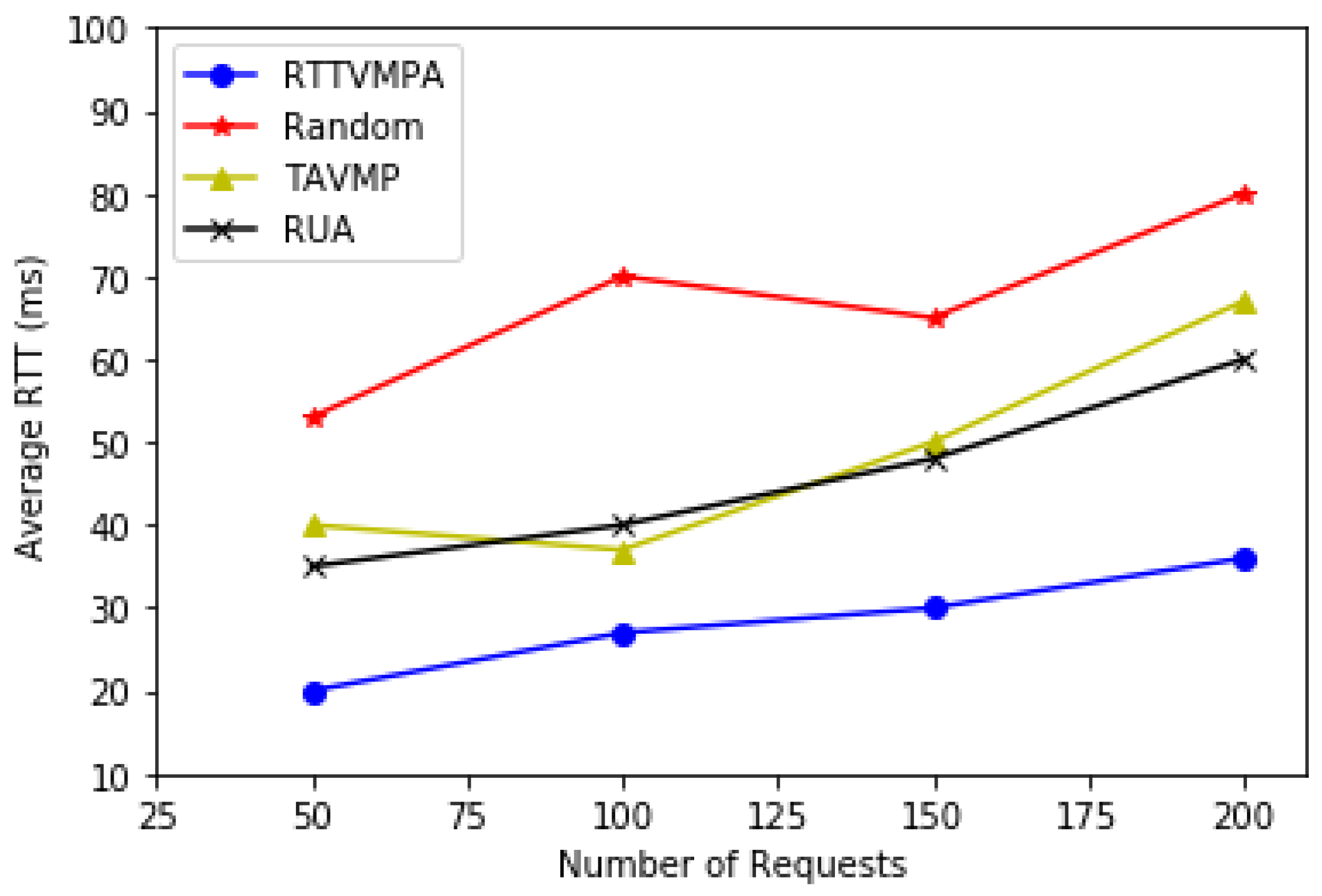
- Random placement: VMs are first placed on the available PMs that have free space for these VMs but the latency for requests is not considered.
- Traffic-aware VM placement (TAVMP) algorithm [23]: TAVMP puts frequently communicating VMs into the same PMs to decrease the traffic between VMs. Such as and that serve one request should be place in the same pod according to TAVMP.
- Remaining utilization-aware (RUA) algorithm [19]: RUA intends to place VMs on less PMs to improve resource utilization. Moreover, RUA could avoid placing VMs that have a large resource requests on the same PMs for reducing resource competition between VMs. Therefore, it can decrease the probability of PMs overloading and keep PMs’ status relatively stable.
6. Conclusions
Acknowledgments
Author Contributions
Conflicts of Interest
References
- Santamaria, A.F.; Serianni, A.; Raimondo, P.; De Rango, F.; Froio, M. Smart wearable device for health monitoring in the Internet of Things (IoT) domain. In Proceedings of the Summer Computer Simulation Conference, Montreal, QC, Canada, 24–27 July 2016; p. 36. [Google Scholar]
- Majeed, A. Internet of things (IoT): A verification framework. In Proceedings of the Computing and Communication Workshop and Conference, Las Vegas, NV, USA, 9–11 January 2017; pp. 1–3. [Google Scholar]
- Perumal, T.; Datta, S.K.; Bonnet, C. IoT device management framework for smart home scenarios. In Proceedings of the 2015 IEEE 4th Global Conference on Consumer Electronics (GCCE), Osaka, Japan, 27–30 October 2015. [Google Scholar]
- Dinh, H.T.; Lee, C.; Niyato, D.; Wang, P. A survey of mobile cloud computing: Architecture, applications and approaches. Wirel. Commun. Mob. Comput. 2013, 13, 1587–1611. [Google Scholar] [CrossRef]
- Gai, K.; Qiu, M.; Zhao, H.; Tao, L.; Zong, Z. Dynamic energy-aware cloudlet-based mobile cloud computing model for green computing. J. Netw. Comput. Appl. 2016, 59, 46–54. [Google Scholar] [CrossRef]
- Morabito, R.; Beijar, N. Enabling data processing at the network edge through lightweight virtualization technologies. In Proceedings of the IEEE International Conference on Sensing, Communication and Networking, London, UK, 27–30 June 2016. [Google Scholar]
- Muller, A.; Wilson, S. Virtualization with Vmware Esx Server; Syngress Publishing: Rockland, MA, USA, 2005. [Google Scholar]
- Lamourine, M. Openstack. Login Mag. USENIX SAGE 2014, 39, 17–20. [Google Scholar]
- Shiva, P.S.M.; Venkatesh, R.R.; Rolia, J.; Islam, M. Virtual Machine Placement. U.S. Patent 9,407,514, 2 August 2016. [Google Scholar]
- Kim, D.; Lee, J. End-to-end one-way delay estimation using one-way delay variation and round-trip time. In Proceedings of the Fourth International Conference on Heterogeneous Networking for Quality, Reliability, Security and Robustness & Workshops, Vancouver, BC, Canada, 14–17 August 2007; pp. 1–8. [Google Scholar]
- Leiserson, C.E. Fat-trees: Universal networks for hardware-efficient supercomputing. IEEE Trans. Comput. 2012, C-34, 892–901. [Google Scholar] [CrossRef]
- Usmani, Z.; Singh, S. A survey of virtual machine placement techniques in a cloud data center. Procedia Comput. Sci. 2016, 78, 491–498. [Google Scholar] [CrossRef]
- Zhan, Z.H.; Liu, X.F.; Gong, Y.J.; Zhang, J.; Chung, S.H.; Li, Y. Cloud computing resource scheduling and a survey of its evolutionary approaches. ACM Comput. Surv. 2015, 47, 1–33. [Google Scholar] [CrossRef]
- Pacini, E.; Mateos, C.; Garino, C.G. Distributed job scheduling based on swarm intelligence: A survey. Comput. Electr. Eng. 2014, 40, 252–269. [Google Scholar] [CrossRef]
- Luan, T.H.; Gao, L.; Li, Z.; Xiang, Y.; Sun, L. Fog computing: Focusing on mobile users at the edge. arXiv 2015, arXiv:1502.01815. [Google Scholar]
- Satyanarayanan, M.; Bahl, P.; Cáceres, R.; Davies, N. The case for vm-based cloudlets in mobile computing. IEEE Pervasive Comput. 2009, 8, 14–23. [Google Scholar] [CrossRef]
- Hirsch, M.; Rodriguez, J.M.; Zunino, A.; Mateos, C. Battery-aware centralized schedulers for CPU-bound jobs in mobile Grids. Pervasive Mob. Comput. 2016, 29, 73–94. [Google Scholar] [CrossRef]
- Fu, X.; Zhou, C. Virtual machine selection and placement for dynamic consolidation in cloud computing environment. Front. Comput. Sci. 2015, 9, 322–330. [Google Scholar] [CrossRef]
- Han, G.; Que, W.; Jia, G.; Shu, L. An efficient virtual machine consolidation scheme for multimedia cloud computing. Sensors 2016, 16, 246. [Google Scholar] [CrossRef] [PubMed]
- Luo, G.; Qian, Z.; Dong, M.; Ota, K.; Lu, S. Network-aware re-scheduling: Towards improving network performance of virtual machines in a data center. In Proceedings of the International Conference on Algorithms and Architectures for Parallel Processing, Dalian, China, 24–27 August 2014; pp. 255–269. [Google Scholar]
- Pan, L.; Wang, D. A cross-entropy-based admission control optimization approach for heterogeneous virtual machine placement in public clouds. Entropy 2016, 18, 95. [Google Scholar] [CrossRef]
- Meng, X.; Pappas, V.; Zhang, L. Improving the scalability of data center networks with traffic-aware virtual machine placement. In Proceedings of the 2010 IEEE Conference on Computer Communications (INFOCOM), San Diego, CA, USA, 15–19 March 2010; pp. 1–9. [Google Scholar]
- Yapicioglu, T.; Oktug, S. A traffic-aware virtual machine placement method for cloud data centers. In Proceedings of the IEEE/ACM International Conference on Utility and Cloud Computing, London, UK, 8–11 December 2014; pp. 299–301. [Google Scholar]
- Ilkhechi, A.R.; Korpeoglu, I. Network-Aware Virtual Machine Placement in Cloud Data Centers with Multiple Traffic-Intensive Components; Elsevier North-Holland, Inc.: Duivendrecht, The Netherlands, 2015; pp. 508–527. [Google Scholar]
- Cohen, R.; Lewin-Eytan, L.; Naor, J.; Raz, D. Almost optimal virtual machine placement for traffic intense data centers. In Proceedings of the 2013 IEEE Conference on Computer Communications (INFOCOM), Turin, Italy, 14–19 April 2013; Volume 12, pp. 355–359. [Google Scholar]
- Al-Fares, M.; Loukissas, A.; Vahdat, A. A scalable, commodity data center network architecture. ACM Sigcomm Comput. Commun. Rev. 2008, 38, 63–74. [Google Scholar] [CrossRef]
- Pedersen, J.M.; Tahir Riaz, M.; Dubalski, B.; Ledzinski, D.; Júnior, J.C.; Patel, A. Using latency as a QoS indicator for global cloud computing services. Concurr. Comput. Pract. Exp. 2014, 25, 2488–2500. [Google Scholar] [CrossRef]
- Lim, J.B.; Yu, H.C.; Gil, J.M.; Lim, J.B.; Yu, H.C.; Gil, J.M. An efficient and energy-aware cloud consolidation algorithm for multimedia big data applications. Symmetry 2017, 9, 184. [Google Scholar] [CrossRef]
- Tang, Y.; Hu, Y.; Zhang, L. A classification-based virtual machine placement algorithm in mobile cloud computing. KSII Trans. Internet Inf. Syst. 2016, 10, 1998–2014. [Google Scholar]
- Keller, M.; Karl, H. Response time-optimized distributed cloud resource allocation. In Proceedings of the 2014 ACM SIGCOMM Workshop on Distributed Cloud Computing, Chicago, IL, USA, 17–22 August 2016; pp. 47–52. [Google Scholar]
- Calheiros, R.N.; Ranjan, R.; Beloglazov, A.; Rose, C.A.F.D.; Buyya, R. Cloudsim: A toolkit for modeling and simulation of cloud computing environments and evaluation of resource provisioning algorithms. Softw. Pract. Exp. 2011, 41, 23–50. [Google Scholar] [CrossRef]
- Long, W.; Lan, Y.; Xia, Q. Using cloudsim to model and simulate cloud computing environment. In Proceedings of the International Conference on Computational Intelligence and Security, Mount Emei, China, 14–15 December 2013; pp. 323–328. [Google Scholar]


| Basic Parameters | Values |
|---|---|
| CPU:2cores×2 1.2 GHz, 6 GB | |
| CPU:2cores×2 1.8 GHz, 8 GB | |
| CPU:1cores 1 GHz, 1 GB | |
| CPU:1cores 1 GHz, 2 GB | |
| Types of | 10 |
| Types of | 10 |
| Number of requests that a VM serves | 4 |
| Methods | Average RTT | Fluctuation of Average RTT |
|---|---|---|
| A_RTTVMPA | Lower | Smooth |
| A_RTTVMPA_VMRA | Higher | Unsmooth |
© 2017 by the authors. Licensee MDPI, Basel, Switzerland. This article is an open access article distributed under the terms and conditions of the Creative Commons Attribution (CC BY) license (http://creativecommons.org/licenses/by/4.0/).
Share and Cite
Quan, L.; Wang, Z.; Ren, F. An RTT-Aware Virtual Machine Placement Method. Information 2018, 9, 4. https://doi.org/10.3390/info9010004
Quan L, Wang Z, Ren F. An RTT-Aware Virtual Machine Placement Method. Information. 2018; 9(1):4. https://doi.org/10.3390/info9010004
Chicago/Turabian StyleQuan, Li, Zhiliang Wang, and Fuji Ren. 2018. "An RTT-Aware Virtual Machine Placement Method" Information 9, no. 1: 4. https://doi.org/10.3390/info9010004
APA StyleQuan, L., Wang, Z., & Ren, F. (2018). An RTT-Aware Virtual Machine Placement Method. Information, 9(1), 4. https://doi.org/10.3390/info9010004