
Computational Modelling and Simulation of Scaffolds for Bone Tissue Engineering


Abstract
:1. Introduction
- How do a scaffold’s architecture and morphological parameters affect its equivalent mechanical properties and permeability?
- How do the scaffolds behave under different loading conditions and different fluid flow conditions while transporting materials such as nutrients and waste materials? How do their equivalent mechanical properties and flow properties vary in such scenarios?
- What kind of material models can be applied for FEM-based structural analysis of scaffolds, and what kind of fluid flow models can be utilised for CFD-based permeability analysis of scaffolds?
2. Computational Modelling of Mechanical Behaviour and Permeability of Scaffolds
2.1. Design of Scaffolds
2.1.1. Essentials of Scaffolds
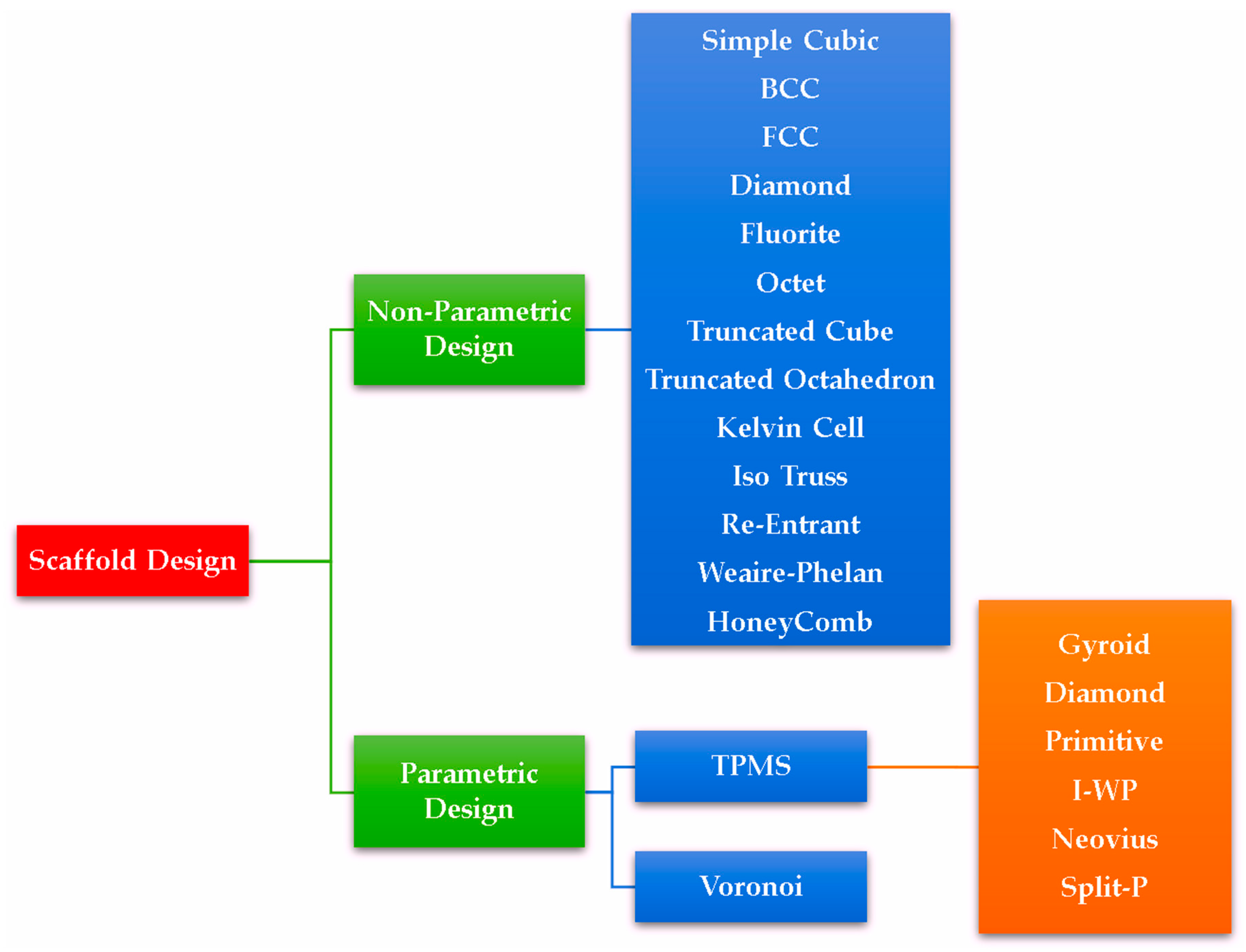
2.1.2. Types of Designs
2.1.3. Influence of Morphological Parameters on Mechanical Behaviour and Permeability
2.2. Simulation of Mechanical Behaviour of BTE Scaffolds
FEM for Prediction of Mechanical Properties

| Model | Predicted Mechanical Properties | Material * | Remarks |
|---|---|---|---|
| Linear isotropic elastic model | Young’s modulus (2D and 3D compressive responses) | PCL | Relationship between compressive modulus and porosities of uniform and gradient diamond pored scaffolds for tissue-engineered meniscus applications [100] |
| BISO model | Effective plastic strain | Twinning-induced plasticity steel | Evaluation of morphological properties on quasi-static behaviour of hallow walled lattice structures under compressive loading [101] |
| Linear isotropic Reuss model | Equivalent Young’s modulus, compression Stiffness | PCL-ACP | Prediction of compressive stiffness of non-parametric scaffolds under linear compressive loading for BTE applications [102] |
| Multilinear isotropic, elastoplastic model | von Mises stress, equivalent plastic strain distributions | Ti6Al4V | Prediction of elastoplastic nature of Split-P TPMS scaffolds for cortical and trabecular bone applications [92] |
| Non-linear elastoplastic model | Plastic deformation | 316L SS | Evaluating the influence of gradient properties of TPMS and circular loading scaffolds on their elastoplastic properties under static compressive loading [103] |
| Raghava–Hill Plasticity Model | Compressive stiffness and strength | Ti-42Nb alloy | Evaluation of effects of unit cells of gyroid and I-WP-based bone scaffolds on their mechanical properties under quasi-static compression [104] |
| Bilinear plasticity model with isotropic hardening (Li–Guo–Shim Model) | Plastic deformation | SS316 Stainless Steel | Prediction of plastic behaviour of Voronoi-based honeycomb scaffolds [105] |
| One term Ogden hyper elastic model | Effective compressive modulus, shear modulus | AG hydrogels | Prediction of non-linear mechanical properties of mesostructure-based hydrogel scaffolds using inverse FE simulations for TE applications [106] |
| 5-term Mooney–Rivlin and 2-term Ogden models | Stress relaxation | AG hydrogels | Evaluation of the hyper-viscoelastic response of hydrogels in compression and tension loading for human articular cartilage [107] |
| 5-term Mooney–Rivlin model, Prony series relaxation model and Generalised Maxwell Model (GMM) | Tensile strength and storage modulus | PLA | Prediction of elastic and viscoelastic behaviours of dog bone-shaped structures under tensile loading [108] |
| Burgers and Maxwell viscoelastic models | Linear viscoelastic behaviour (creep and recovery) | Polypropylene | Prediction of viscoelastic deformation at different pressure levels [109] |
| Riemann–Liouville-based fractional viscoelastic model | Viscoelastic (creep recovery and cyclic response) deformations | POM | Development of a non-linear multiaxial viscoelastic model to evaluate time-dependent responses of isotropic materials under small deformation gradients [110] |
| Maxwell, Kelvin, and Burger models | Storage and loss moduli | PLA | Prediction of time-dependent viscoelastic behaviour of orthotropic viscoelastic materials [111] |
| Mori–Tanaka model | Effective elastic moduli (Young’s modulus) and Poisson’s ratio | Acrylic-based photopolymers | Prediction of mechanical properties of mix-materials composites based foams with different porosities [112] |
| Crushable foam plasticity model | Elastic modulus under quasi-static compression | VeroClear | Prediction of damage behaviour of polymer bone scaffolds with cubic and hexagonal architecture [113] |
| Johnson–Cook (JC) damage deformation model | Compressive stress distribution | Ti6Al4V-PCL | Performance evaluation of failure and mechanical strength mechanisms of interpenetrating phase composites (IPCs) under compressive loading for orthopaedic implants [114] |
| Arruda–Boyce (AB) Model | Compressive uniaxial modulus and strength | PA-12 | Prediction of viscoelastic behaviour of polymeric gyroid scaffolds of sheet network architecture with non-identical relative densities [115] |
2.3. Simulation of Permeability of BTE Scaffolds
Need for Permeability Simulation
- (i)
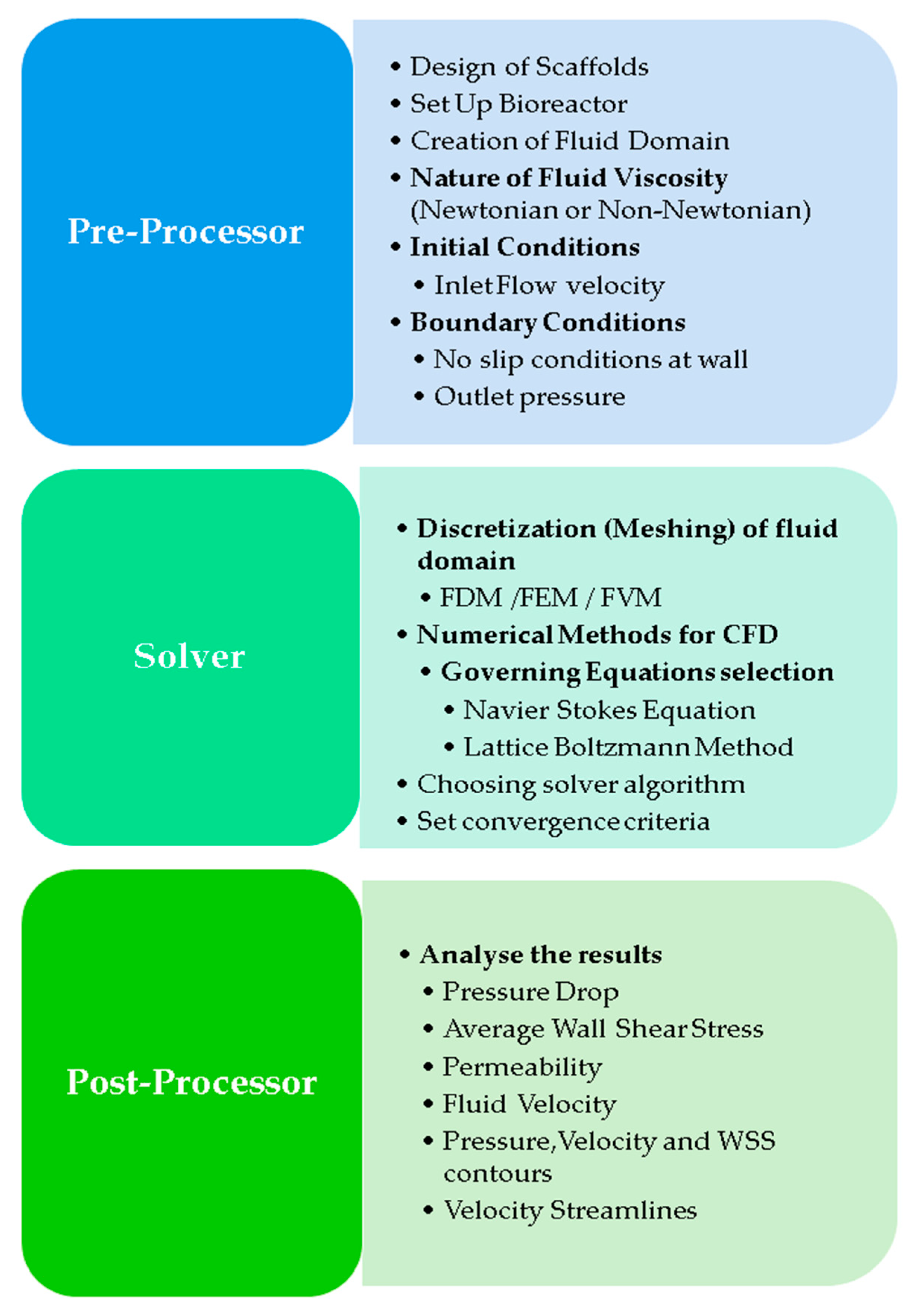
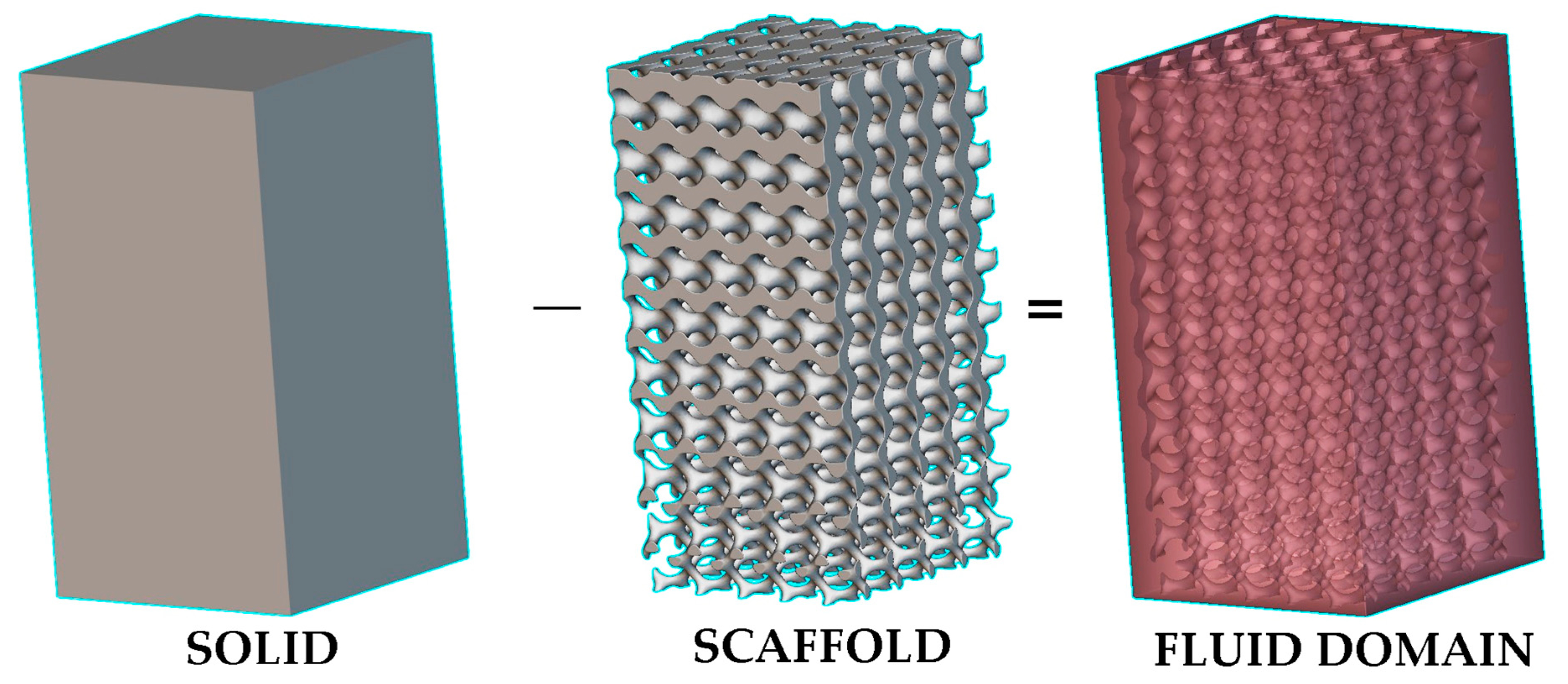
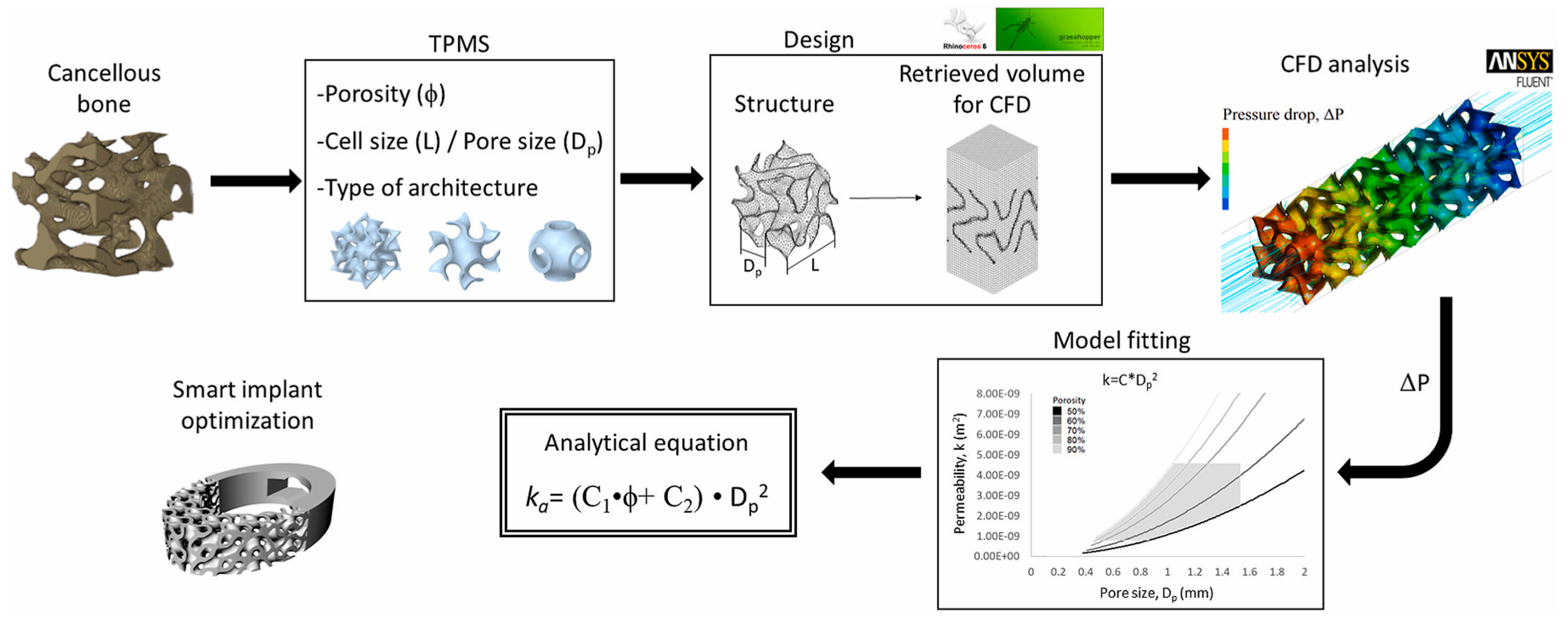
- Preprocessing: This initial phase involves designing the scaffold geometry and setting up the bioreactor geometry. Then, the fluid domain or volume is extracted using Boolean differentiation of scaffold geometry with the bioreactor geometry (Figure 14). The flow of either Newtonian or non-Newtonian fluids must be represented in terms of boundary conditions, including the inlet flow velocity, the outlet pressure, and the viscosity of the given fluid. These boundary conditions describe the given fluid’s interaction with the scaffold’s surface [139,140].
- (ii)
- Solver: This module focuses on applying numerical methods within CFD to solve the governing equations, such as the Navier–Stokes (NS) equations [141] for continuous flow modelling or the Lattice Boltzmann Method (LBM) for discrete flow modelling [142]. Traditionally, finite difference methods (FDM) using grids for the discretisation of a given geometry were applied to solve the governing equations, but they were inefficient for complex geometries [143]. The methods of FEM and the finite volume method (FVM) have since gained popularity in CFD simulations for complex and curved geometries. In FEM, geometry is divided into more minor finite elements, primarily using mesh nodes. At the same time, FVM discretises the problem into small control volumes centred around mesh points, focusing on the conservation of physical quantities across each volume [144]. FEM is highly versatile and is particularly effective for problems involving complex geometries and irregular shapes. However, it becomes very computationally expensive for models with a large number of elements. Comparatively, FVM is often considered more efficient for problems involving fluid dynamics and heat transfer, mainly because it directly applies the conservation laws of mass, momentum, and energy over control volumes [145]. This type makes it naturally suited for the analysis of flow problems and can lead to more accurate results in these cases with less computational effort.
- (iii)
- Post Processing: After the CFD simulation, a post-processing module is used to analyse the results, including the velocity streamlines, the average WSS, and pressure and velocity contours. This analysis provides insights into how a scaffold’s architecture affects fluid flow, offering valuable information about permeability, fluid velocity, and WSS [146,147].
| Model | Predicted Fluid and Other Properties | Fluid Material * | Remarks |
|---|---|---|---|
| Steady-state Laminar fluid flow model | Permeability and WSS | Blood (Density: 1050 kg/m3, viscosity: 0.004 kg/(m.s), inlet velocity: 0.3 mL/min) | Evaluation of the influence of morphological parameters of uniform and graded Schwartz-Primitive scaffolds on their permeability properties for trabecular bone applications [159] |
| Pressure drops, permeability, and WSS | Blood (Viscosity: 3.2 × 10⁻³ Pa.s, density: 1060 kg/m3, inlet velocity: 1 mm/s) | Evaluation of fluid transport properties of Tra-PLA/PDA/COS@EU scaffolds for trabecular bone repair [116] | |
| Laminar fluid flow model with Wang–Tarbell formula for permeability | WSS, flow rate, permeability, and mass flow | α-MEM (Density: 1000 kg/m3, viscosity: 1.45 × 10⁻³ Pa.s, inlet velocity: 1 mm/s) | Prediction of hydrodynamic responses for osteogenesis inside titanium alloy-based TPMS and Voronoi scaffolds [160] |
| Incompressible Laminar Newtonian fluid model and Discrete phase model (DPM) | Permeability, FSS, and distribution of stem cells | Blood (Density: 1060 kg/cm3, viscosity: 0.003 kg/m/s) MSCs (Diameter: 12.7 µm, and density: 1140 kg(m3) | Prediction of fluid shear stress on Voronoi scaffold surface, MSCs attachment on the scaffold and mechano-regulation osteoblast differentiation (MrOD) [161] |
| Incompressible Newtonian fluid model and Machine Learning (ML) | Permeability, pressure drop and specific surface area | Body Fluid (Density: 1056 kg/m3, viscosity: 0.0045 Pa.s) | Prediction of WSS using support vector machines and eXtreme Gradient Boosting ML models to minimise the computational cost of CFD simulations [162] |
| Power law models for incompressible non-Newtonian fluid | Permeability and WSS | Blood (Density: 1050 kg/m3, minimum and maximum dynamic viscosities: 0.001 and 0.708 kg/m/s, consistency index: 0.017 kg.sn−2/m, power law exponent: 0.708) | Prediction of transport properties inside open cell Neovius TPMS scaffolds for BTE [163] |
| Carreau–Yasuda non-Newtonian flow model and DPM | Pressure drops, specific surface area, and cell seeding efficiency | Blood (Density: 1050 kg/m3, inlet velocity: 0.1 mm/s, lower and upper viscosities: 0.25 and 0.0035 Pa.s) MSCs (density: 1130 kg/m3, diameter: 10 µm and initial cell number: 3600) | Influence of pore size of TPMS scaffolds on cell seeding [164] |
| FEM-based CFD model with Brinkmann equation for shear stress in scaffold medium | Flow velocity and shear stress | Culture medium (Inlet flow rate: 2 mL/min) | Development of CFD models for evaluation of perfusion bioreactor systems to predict flow parameters of β-Tricalcium phosphate scaffolds in BTE [165] |
| RANS K-Turbulence model and Transport of diluted specimen model | Shear stress, flow distribution and glucose diffusion | Water (Mass inflow: 1.5 g/min), Glucose in tissues (Diffusion coefficient: 6 × 10⁻¹⁰ m2/s, elimination rate: −1.157 + 10−4 mol/(m3.s)) | Prediction of shear stress and nutrient distribution into tissues in a perfusion bioreactor [166] |
| SST K-ω Turbulence Model | Pressure drops, Flow velocity distribution and WSS | DMEM (Density: 1 g/cm3, dynamic viscosity: 1.45 mPa.s, inlet velocity: 0.1, 1 to 10 mm/s, Thermal conductivity: 91 W/(mK), Specific Heat: 1050 J/(kg K), Electrical resistivity: 6.20 × 10⁻⁸ Ω m) | Prediction of permeability of Magnesium-based trabecular bone implants [167] |
| Vertex hydrodynamics (VH) model | Elastic energy (Cell distribution), Total/specific number of cells, intracellular pressure, and normalised shear stress | Water | Simulation of tissue growth at FGS in perfusion bioreactors [168] |
| LBM-based mesoscopic model | Cell attachment rate and seeding efficiency | MSCs (Stiffness: 50 to 150 µN, bond strength: 0.025 to 0.125 pN/nm, Binding force: 10 to 50 pN) | Simulation of MSCs seeding on uniform pore scaffold to evaluate cell deformation and attachment [169] |
| Two-relaxation time (TRT) LBM with Michaelis–Menten-like kinetic model | Fluid flow and oxygen transport | α-MEM (Density: 993 kg/m3, viscosity: 10−3 Pa.s, inlet velocity: 1.47 mm/s, oxygen diffusion coefficient: 3 × 10⁻⁹ m2/s) | Prediction of oxygen consumption to the cells (MC3T3E1 Preosteoblasts) for optimal in vitro BTE methods of polysaccharide hydrogel scaffolds [170] |
3. Conclusions
Supplementary Materials
Author Contributions
Funding
Data Availability Statement
Acknowledgments
Conflicts of Interest
References
- Martin Bruce, R.; Burr David, B.; Sharkey, N.A.; Fyhrie David, P. Skeletal Tissue Mechanics, 2nd ed.; Springer: Berlin/Heidelberg, Germany, 2015. [Google Scholar] [CrossRef]
- Heimes, D.; Pabst, A.; Becker, P.; Hartmann, A.; Kloss, F.; Tunkel, J.; Smeets, R.; Kämmerer, P.W. Comparison of Morbidity-Related Parameters between Autologous and Allogeneic Bone Grafts for Alveolar Ridge Augmentation from Patients’ Perspective—A Questionnaire-Based Cohort Study. Clin. Implant. Dent. Relat. Res. 2024, 26, 170–182. [Google Scholar] [CrossRef]
- Wu, Y.; Ji, Y.; Lyu, Z. 3D Printing Technology and Its Combination with Nanotechnology in Bone Tissue Engineering. Biomed. Eng. Lett. 2024, 1–14. [Google Scholar] [CrossRef]
- Gou, Y.; Huang, Y.; Luo, W.; Li, Y.; Zhao, P.; Zhong, J.; Dong, X.; Guo, M.; Li, A.; Hao, A.; et al. Adipose-Derived Mesenchymal Stem Cells (MSCs) Are a Superior Cell Source for Bone Tissue Engineering. Bioact. Mater. 2024, 34, 51–63. [Google Scholar] [CrossRef]
- Zhang, J.; Suttapreyasri, S.; Leethanakul, C.; Samruajbenjakun, B. Fabrication of Vascularized Tissue-Engineered Bone Models Using Triaxial Bioprinting. J. Biomed. Mater. Res. A 2024, 1–14. [Google Scholar] [CrossRef]
- Liu, T.; Wang, Y.; Kuang, T. Oriented Porous Polymer Scaffolds in Tissue Engineering: A Comprehensive Review of Preparation Strategies and Applications. Macromol. Mater. Eng. 2024, 309, 2300246. [Google Scholar] [CrossRef]
- Xu, Y.; Zhang, S.; Ding, W.; Du, H.; Li, M.; Li, Z.; Chen, M. Additively-Manufactured Gradient Porous Bio-Scaffolds: Permeability, Cytocompatibility and Mechanical Properties. Compos. Struct. 2024, 336, 118021. [Google Scholar] [CrossRef]
- Mostajeran, H.; Baheiraei, N.; Bagheri, H. Effects of Cerium-Doped Bioactive Glass Incorporation on an Alginate/Gelatin Scaffold for Bone Tissue Engineering: In Vitro Characterizations. Int. J. Biol. Macromol. 2024, 255, 128094. [Google Scholar] [CrossRef]
- Abdollahi, F.; Saghatchi, M.; Paryab, A.; Malek Khachatourian, A.; Stephens, E.D.; Toprak, M.S.; Badv, M. Angiogenesis in Bone Tissue Engineering via Ceramic Scaffolds: A Review of Concepts and Recent Advancements. Biomater. Adv. 2024, 159, 213828. [Google Scholar] [CrossRef]
- Zhang, T.; Li, J.; Wang, Y.; Han, W.; Wei, Y.; Hu, Y.; Liang, Z.; Lian, X.; Huang, D. Hydroxyapatite/Polyurethane Scaffolds for Bone Tissue Engineering. Tissue Eng. Part. B Rev. 2024, 30, 60–73. [Google Scholar] [CrossRef]
- Han, X.; Saiding, Q.; Cai, X.; Xiao, Y.; Wang, P.; Cai, Z.; Gong, X.; Gong, W.; Zhang, X.; Cui, W. Intelligent Vascularized 3D/4D/5D/6D-Printed Tissue Scaffolds. Nano-Micro Lett. 2023, 15, 239. [Google Scholar] [CrossRef]
- Qi, J.; Yu, T.; Hu, B.; Wu, H.; Ouyang, H. Current Biomaterial-Based Bone Tissue Engineering and Translational Medicine. Int. J. Mol. Sci. 2021, 22, 10233. [Google Scholar] [CrossRef]
- Laubach, M.; Suresh, S.; Herath, B.; Wille, M.L.; Delbrück, H.; Alabdulrahman, H.; Hutmacher, D.W.; Hildebrand, F. Clinical Translation of a Patient-Specific Scaffold-Guided Bone Regeneration Concept in Four Cases with Large Long Bone Defects. J. Orthop. Translat. 2022, 34, 73–84. [Google Scholar] [CrossRef]
- D’Andrea, L.; Gastaldi, D.; Baino, F.; Verné, E.; Schwentenwein, M.; Örlygsson, G.; Vena, P. Computational Models for the Simulation of the Elastic and Fracture Properties of Highly Porous 3D-Printed Hydroxyapatite Scaffolds. Int. J. Numer. Method. Biomed. Eng. 2024, 40, e3795. [Google Scholar] [CrossRef]
- Wang, M.; Jiang, G.; Yang, H.; Jin, X. Computational Models of Bone Fracture Healing and Applications: A Review. Biomed. Tech. 2024. [Google Scholar] [CrossRef]
- Drakoulas, G.; Gortsas, T.; Polyzos, E.; Tsinopoulos, S.; Pyl, L.; Polyzos, D. An Explainable Machine Learning-Based Probabilistic Framework for the Design of Scaffolds in Bone Tissue Engineering. Biomech. Model. Mechanobiol. 2024, 2024, 1–26. [Google Scholar] [CrossRef]
- Kallivokas, S.V.; Kontaxis, L.C.; Psarras, S.; Roumpi, M.; Ntousi, O.; Kakkos, I.; Deligianni, D.; Matsopoulos, G.K.; Fotiadis, D.I.; Kostopoulos, V. A Combined Computational and Experimental Analysis of PLA and PCL Hybrid Nanocomposites 3D Printed Scaffolds for Bone Regeneration. Biomedicines 2024, 12, 261. [Google Scholar] [CrossRef]
- Huo, L.; Li, Q.; Jiang, L.; Jiang, H.; Zhao, J.; Yang, K.; Dong, Q.; Shao, Y.; Chu, C.; Xue, F.; et al. Porous Mg–Zn–Ca Scaffolds for Bone Repair: A Study on Microstructure, Mechanical Properties and in Vitro Degradation Behavior. J. Mater. Sci. Mater. Med. 2024, 35, 1–8. [Google Scholar] [CrossRef]
- Li, Z.; Chen, Z.; Chen, X.; Zhao, R. Design and Evaluation of TPMS-Inspired 3D-Printed Scaffolds for Bone Tissue Engineering: Enabling Tailored Mechanical and Mass Transport Properties. Compos. Struct. 2024, 327, 117638. [Google Scholar] [CrossRef]
- Khoshgoftar, M.J.; Ansari, H. Design and Analysis of Unit Cell Geometry to Improve Mechanical Properties and Surface-to-Volume Ratio of Used Scaffold in Treating Damaged Bone Tissue. Adv. Eng. Mater. 2024, 26, 2301600. [Google Scholar] [CrossRef]
- Peng, X.; Li, S.; He, D.; Li, J.; Qu, S.; Jin, Z. Expanding the Mechanical and Mass-Transport Combination for Bone Scaffolds: Through Stretched Structure. Compos. Struct. 2024, 329, 117783. [Google Scholar] [CrossRef]
- Bowlin, G.L.; Lee, M.-C.; Pan, C.-T.; Chen, W.-F.; Lin, M.-C.; Shiue, Y.-L. Design, Manufacture, and Characterization of a Critical-Sized Gradient Porosity Dual-Material Tibial Defect Scaffold. Bioengineering 2024, 11, 308. [Google Scholar] [CrossRef]
- Luo, Y.; Kim, J. Achieving the Ideal Balance between Biological and Mechanical Requirements in Composite Bone Scaffolds through a Voxel-Based Approach. Biomech. Model. Mechanobiol. 2024, 1–14. [Google Scholar] [CrossRef] [PubMed]
- Acar, A.A.; Daskalakis, E.; Bartolo, P.; Weightman, A.; Cooper, G.; Blunn, G.; Koc, B. Customized Scaffolds for Large Bone Defects Using 3D-Printed Modular Blocks from 2D-Medical Images. Biodes Manuf. 2024, 7, 74–87. [Google Scholar] [CrossRef]
- Zou, Z.; Cheong, V.S.; Fromme, P. Bone Remodelling Prediction Using Mechanical Stimulus with Bone Connectivity Theory in Porous Implants. J. Mech. Behav. Biomed. Mater. 2024, 153, 106463. [Google Scholar] [CrossRef] [PubMed]
- Shalimov, A.; Tashkinov, M.; Silberschmidt, V.V. Failure of Trabecular Bone: XFEM Modelling of Multiple Crack Growth. Theor. Appl. Fract. Mech. 2024, 130, 104338. [Google Scholar] [CrossRef]
- Zhao, Y.; Wu, Q.; Zhou, H.; Zhao, C.; Wu, L. Investigation on Mechanical Properties of Ti-6Al-4 V Multilayer Micro-Lattice Biomaterials under Dynamic Compression Loading. J. Alloys Compd. 2024, 977, 173419. [Google Scholar] [CrossRef]
- Mao, R.; Lai, Y.; Li, D.; Huang, Y.; Wang, L.; Luo, F.; Chen, Y.; Lu, J.; Ge, X.; Liu, Y.; et al. Flow Channel Performance in 3D Printed Hydroxyapatite Scaffolds to Improve Metabolism and Tissue Ingrowth in Flat Bone Repair. Compos. B Eng. 2023, 259, 110727. [Google Scholar] [CrossRef]
- Drakoulas, G.; Gortsas, T.; Tsinopoulos, S.; Polyzos, D. A Numerical Study on the Early-Stage Performance of 3D Composite PLA/316L Scaffolds in Tissue Engineering. In Advances in Computational Mechanics and Applications; Springer: Berlin/Heidelberg, Germany, 2024; pp. 28–44. [Google Scholar] [CrossRef]
- Tajvar, S.; Hadjizadeh, A.; Samandari, S.S. Scaffold Degradation in Bone Tissue Engineering: An Overview. Int. Biodeterior. Biodegrad. 2023, 180, 105599. [Google Scholar] [CrossRef]
- Sestito, J.M.; Harris, T.A.L.; Wang, Y. Structural Descriptor and Surrogate Modeling for Design of Biodegradable Scaffolds. J. Mech. Behav. Biomed. Mater. 2024, 152, 106415. [Google Scholar] [CrossRef]
- Asbai-Ghoudan, R.; Nasello, G.; Pérez, M.Á.; Verbruggen, S.W.; Ruiz de Galarreta, S.; Rodriguez-Florez, N. In Silico Assessment of the Bone Regeneration Potential of Complex Porous Scaffolds. Comput. Biol. Med. 2023, 165, 107381. [Google Scholar] [CrossRef]
- Alshammari, A.; Alabdah, F.; Wang, W.; Cooper, G. Virtual Design of 3D-Printed Bone Tissue Engineered Scaffold Shape Using Mechanobiological Modeling: Relationship of Scaffold Pore Architecture to Bone Tissue Formation. Polymers 2023, 15, 3918. [Google Scholar] [CrossRef] [PubMed]
- Boaretti, D.; Marques, F.C.; Ledoux, C.; Singh, A.; Kendall, J.J.; Wehrle, E.; Kuhn, G.A.; Bansod, Y.D.; Schulte, F.A.; Müller, R. Trabecular Bone Remodeling in the Aging Mouse: A Micro-Multiphysics Agent-Based in Silico Model Using Single-Cell Mechanomics. Front. Bioeng. Biotechnol. 2023, 11, 1091294. [Google Scholar] [CrossRef] [PubMed]
- Rosa, N.; Pouca, M.V.; Torres, P.M.C.; Olhero, S.M.; Jorge, R.N.; Parente, M. Influence of Structural Features in the Performance of Bioceramic-Based Composite Scaffolds for Bone Engineering Applications: A Prediction Study. J. Manuf. Process. 2023, 90, 391–405. [Google Scholar] [CrossRef]
- Beheshtizadeh, N.; Farzin, A.; Rezvantalab, S.; Pazhouhnia, Z.; Lotfibakhshaiesh, N.; Ai, J.; Noori, A.; Azami, M. 3D Printing of Complicated GelMA-Coated Alginate/Tri-Calcium Silicate Scaffold for Accelerated Bone Regeneration. Int. J. Biol. Macromol. 2023, 229, 636–653. [Google Scholar] [CrossRef] [PubMed]
- Liu, J.; Wang, K.; Wang, R.; Yin, Z.; Zhou, X.; Xu, A.; Zhang, X.; Li, Y.; Wang, R.; Zhang, S.; et al. Effect of Lattice Type on Biomechanical and Osseointegration Properties of 3D-Printed Porous Ti6Al4V Scaffolds. Int. J. Bioprinting 2024, 10, 1698. [Google Scholar] [CrossRef]
- Mashhadi Keshtiban, M.; Taghvaei, H.; Noroozi, R.; Eskandari, V.; Arif, Z.U.; Bodaghi, M.; Bardania, H.; Hadi, A. Biological and Mechanical Response of Graphene Oxide Surface-Treated Polylactic Acid 3D-Printed Bone Scaffolds: Experimental and Numerical Approaches. Adv. Eng. Mater. 2024, 26, 2301260. [Google Scholar] [CrossRef]
- Velasco, M.A.; Narváez-Tovar, C.A.; Garzón-Alvarado, D.A. Review Article Design, Materials, and Mechanobiology of Biodegradable Scaffolds for Bone Tissue Engineering. BioMed. Res. Int. 2015, 2015, 1–21. [Google Scholar] [CrossRef] [PubMed]
- Al-Allaq, A.A.; Kashan, J.S.; Abdul-Kareem, F.M. In Vivo Investigations of Polymers in Bone Tissue Engineering: A Review Study. Int. J. Polym. Mater. Polym. Biomater. 2024, 1–16. [Google Scholar] [CrossRef]
- Katebifar, S.; Arul, M.; Abdulmalik, S.; Yu, X.; Alderete, J.F.; Kumbar, S.G. Novel High-Strength Polyester Composite Scaffolds for Bone Regeneration. Polym. Adv. Technol. 2023, 34, 3770–3791. [Google Scholar] [CrossRef]
- Paltanea, G.; Manescu, V.; Antoniac, I.; Antoniac, A.; Nemoianu, I.V.; Robu, A.; Dura, H. A Review of Biomimetic and Biodegradable Magnetic Scaffolds for Bone Tissue Engineering and Oncology. Int. J. Mol. Sci. 2023, 24, 4312. [Google Scholar] [CrossRef]
- Schulze, F.; Lang, A.; Schoon, J.; Wassilew, G.I.; Reichert, J. Scaffold Guided Bone Regeneration for the Treatment of Large Segmental Defects in Long Bones. Biomedicines 2023, 11, 325. [Google Scholar] [CrossRef] [PubMed]
- Ataollahi, S. A Review on Additive Manufacturing of Lattice Structures in Tissue Engineering. Bioprinting 2023, 35, e00304. [Google Scholar] [CrossRef]
- Liu, K.; Zhou, Q.; Zhang, X.; Ma, L.; Xu, B.; He, R. Morphologies, Mechanical and in Vitro Behaviors of DLP-Based 3D Printed HA Scaffolds with Different Structural Configurations. RSC Adv. 2023, 13, 20830–20838. [Google Scholar] [CrossRef] [PubMed]
- Pasini, C.; Pandini, S.; Ramorino, G.; Sartore, L. Tailoring the Properties of Composite Scaffolds with a 3D-Printed Lattice Core and a Bioactive Hydrogel Shell for Tissue Engineering. J. Mech. Behav. Biomed. Mater. 2024, 150, 106305. [Google Scholar] [CrossRef] [PubMed]
- Ali, D. The Behaviour of Scaffolds for Bone under Torsional Loading with Different Architectures: A Numerical Analysis. In 2020 Medical Technologies Congress (TIPTEKNO), Anatalya, Turkey; IEEE: New York, NY, USA, 2020; pp. 1–3. [Google Scholar] [CrossRef]
- Karri, C.P.; Kambagowni, V. Finite Element Analysis Approach for Optimal Design and Mechanical Performance Prediction of Additive Manufactured Sandwich Lattice Structures. J. Inst. Eng. (India) Ser. D, 2024; 1–16. [Google Scholar] [CrossRef]
- Roohani, I.; Entezari, A.; Zreiqat, H. Liquid Crystal Display Technique (LCD) for High Resolution 3D Printing of Triply Periodic Minimal Surface Lattices Bioceramics. Addit. Manuf. 2023, 74, 103720. [Google Scholar] [CrossRef]
- Talebi, S.; Sadighi, M. Simulation of Compression Behavior of Porous Structure Based on Different Space-Filling Unit Cells under Quasi-Static Loading. Mech. Based Des. Struct. Mach. 2023, 51, 2535–2549. [Google Scholar] [CrossRef]
- Li, L.; Wang, P.; Liang, H.; Jin, J.; Zhang, Y.; Shi, J.; Zhang, Y.; He, S.; Mao, H.; Xue, B.; et al. Design of a Haversian System-like Gradient Porous Scaffold Based on Triply Periodic Minimal Surfaces for Promoting Bone Regeneration. J. Adv. Res. 2023, 54, 89–104. [Google Scholar] [CrossRef] [PubMed]
- Araya, M.; Jaskari, M.; Rautio, T.; Guillén, T.; Järvenpää, A. Assessing the Compressive and Tensile Properties of TPMS-Gyroid and Stochastic Ti64 Lattice Structures: A Study on Laser Powder Bed Fusion Manufacturing for Biomedical Implants. J. Sci. Adv. Mater. Devices 2024, 9, 100663. [Google Scholar] [CrossRef]
- Vaiani, L.; Uva, A.E.; Boccaccio, A. Structural and Topological Design of Conformal Bilayered Scaffolds for Bone Tissue Engineering. Thin-Walled Struct. 2023, 192, 111209. [Google Scholar] [CrossRef]
- Song, J.; Li, L.; Fang, L.; Zhang, E.; Zhang, Y.; Zhang, Z.; Vangari, P.; Huang, Y.; Tian, F.; Zhao, Y.; et al. Advanced Strategies of Scaffolds Design for Bone Regeneration. BMEMat 2023, 1, e12046. [Google Scholar] [CrossRef]
- Zhang, H.; Wang, M.; Wu, R.; Guo, J.; Sun, A.; Li, Z.; Ye, R.; Xu, G.; Cheng, Y. From Materials to Clinical Use: Advances in 3D-Printed Scaffolds for Cartilage Tissue Engineering. Phys. Chem. Chem. Phys. 2023, 25, 24244–24263. [Google Scholar] [CrossRef]
- Vigil, J.; Lewis, K.; Norris, N.; Karakoç, A.; Becker, T.A. Design, Fabrication, and Characterisation of 3D-Printed Multiphase Scaffolds Based on Triply Periodic Minimal Surfaces. Adv. Polym. Technol. 2024, 2024, 1–7. [Google Scholar] [CrossRef]
- Gao, T.; Liu, K.; Wang, X.; Wei, K.; Wang, Z. Multi-Level Mechanism of Biomimetic TPMS Hybridizations with Tailorable Global Homogeneity and Heterogeneity. Extreme Mech. Lett. 2024, 68, 102136. [Google Scholar] [CrossRef]
- Zhou, Y.; Isaksson, P.; Persson, C. An Improved Trabecular Bone Model Based on Voronoi Tessellation. J. Mech. Behav. Biomed. Mater. 2023, 148, 106172. [Google Scholar] [CrossRef]
- Liu, B.; Wei, X.; Cao, W.; Lu, P.; Wang, X. A Novel Method to Design Gradient Porous Structures with Conformal Density. Thin-Walled Struct. 2024, 197, 111623. [Google Scholar] [CrossRef]
- Al-Ketan, O.; Lee, D.-W.; Abu Al-Rub, R.K. Mechanical Properties of Additively-Manufactured Sheet-Based Gyroidal Stochastic Cellular Materials. Addit. Manuf. 2021, 48, 102418. [Google Scholar] [CrossRef]
- Vafaeefar, M.; Moerman, K.M.; Vaughan, T.J. Experimental and Computational Analysis of Energy Absorption Characteristics of Three Biomimetic Lattice Structures under Compression. J. Mech. Behav. Biomed. Mater. 2024, 151, 106328. [Google Scholar] [CrossRef]
- He, L.; Zhao, M.; Cheung, J.P.Y.; Zhang, T.; Ren, X. Gaussian Random Field-Based Characterization and Reconstruction of Cancellous Bone Microstructure Considering the Constraint of Correlation Structure. J. Mech. Behav. Biomed. Mater. 2024, 152, 106443. [Google Scholar] [CrossRef]
- Deng, W.; Kumar, S.; Vallone, A.; Kochmann, D.M.; Greer, J.R. AI-Enabled Materials Design of Non-Periodic 3D Architectures With Predictable Direction-Dependent Elastic Properties. Adv. Mater. 2024, 2308149. [Google Scholar] [CrossRef]
- Alsheghri, A.; Reznikov, N.; Piché, N.; McKee, M.D.; Tamimi, F.; Song, J. Optimization of 3D Network Topology for Bioinspired Design of Stiff and Lightweight Bone-like Structures. Mater. Sci. Eng. C 2021, 123, 112010. [Google Scholar] [CrossRef]
- Rajaraman, S.; Rakshit, S. Multiscale Topology Optimization of Pelvic Bone for Combined Walking and Running Gait Cycles. Comput. Methods Biomech. Biomed. Eng. 2023, 1–17. [Google Scholar] [CrossRef]
- Pugliese, R.; Graziosi, S. Biomimetic Scaffolds Using Triply Periodic Minimal Surface-Based Porous Structures for Biomedical Applications. SLAS Technol. 2023, 28, 165–182. [Google Scholar] [CrossRef]
- Li, Z.; Chen, Z.; Chen, X.; Zhao, R. Multi-Objective Optimization for Designing Porous Scaffolds with Controllable Mechanics and Permeability: A Case Study on Triply Periodic Minimal Surface Scaffolds. Compos. Struct. 2024, 333, 117923. [Google Scholar] [CrossRef]
- Pemmada, R.; Telang, V.S.; Tandon, P.; Thomas, V. Patient-Specific Mechanical Analysis of PCL Periodontal Membrane: Modeling and Simulation. J. Mech. Behav. Biomed. Mater. 2024, 151, 106397. [Google Scholar] [CrossRef]
- Vaquette, C.; Carluccio, D.; Batstone, M.; Ivanovski, S. Workflow for Fabricating 3D-Printed Resorbable Personalized Porous Scaffolds for Orofacial Bone Regeneration. Methods Mol. Biol. 2023, 2588, 485–492. [Google Scholar] [CrossRef]
- Li, Y.; Li, J.; Jiang, S.; Zhong, C.; Zhao, C.; Jiao, Y.; Shen, J.; Chen, H.; Ye, M.; Zhou, J.; et al. The Design of Strut/TPMS-Based Pore Geometries in Bioceramic Scaffolds Guiding Osteogenesis and Angiogenesis in Bone Regeneration. Mater. Today Bio. 2023, 20, 100667. [Google Scholar] [CrossRef]
- Wang, C.; Liu, J.; Min, S.; Liu, Y.; Liu, B.; Hu, Y.; Wang, Z.; Mao, F.; Wang, C.; Ma, X.; et al. The Effect of Pore Size on the Mechanical Properties, Biodegradation and Osteogenic Effects of Additively Manufactured Magnesium Scaffolds after High Temperature Oxidation: An in Vitro and in Vivo Study. Bioact. Mater. 2023, 28, 537–548. [Google Scholar] [CrossRef]
- Eivazzadeh-Keihan, R.; Sadat, Z.; Lalebeigi, F.; Naderi, N.; Panahi, L.; Ganjali, F.; Mahdian, S.; Saadatidizaji, Z.; Mahdavi, M.; Chidar, E.; et al. Effects of Mechanical Properties of Carbon-Based Nanocomposites on Scaffolds for Tissue Engineering Applications: A Comprehensive Review. Nanoscale Adv. 2024, 6, 337–366. [Google Scholar] [CrossRef]
- Naghavi, S.A.; Tamaddon, M.; Marghoub, A.; Wang, K.; Bahrami Babam-Iri, B.; Hazeli, K.; Xu, W.; Lu, X.; Sun, C.; Wang, L.; et al. Mechanical Characterisation and Numerical Modelling of TPMS-Based Gyroid and Diamond Ti6Al4V Scaffolds for Bone Implants: An Integrated Approach for Translational Consideration. Bioengineering 2022, 2022, 504. [Google Scholar] [CrossRef]
- Papazoglou, D.P.; Neidhard-Doll, A.T.; Pinnell, M.F.; Erdahl, D.S.; Osborn, T.H. Compression and Tensile Testing of L-PBF Ti-6Al-4V Lattice Structures with Biomimetic Porosities and Strut Geometries for Orthopedic Implants. Metals 2024, 14, 232. [Google Scholar] [CrossRef]
- Zhang, S.; Vijayavenkataraman, S.; Lu, W.F.; Fuh, J.Y.H. A Review on the Use of Computational Methods to Characterise, Design, and Optimise Tissue Engineering Scaffolds, with a Potential in 3D Printing Fabrication. J. Biomed. Mater. Res. B Appl. Biomater. 2019, 107, 1329–1351. [Google Scholar] [CrossRef]
- Liu, B.; Liu, J.; Wang, C.; Wang, Z.; Min, S.; Wang, C.; Zheng, Y.; Wen, P.; Tian, Y. High Temperature Oxidation Treated 3D Printed Anatomical WE43 Alloy Scaffolds for Repairing Periarticular Bone Defects: In Vitro and in Vivo Studies. Bioact. Mater. 2024, 32, 177–189. [Google Scholar] [CrossRef]
- Shirzad, M.; Bodaghi, M.; Oh, D.; Yi, M.; Nam, S.Y. Design and Optimization of Bioinspired Auxetic Structure for Biomedical Applications. Eur. J. Mech. A/Solids 2024, 103, 105139. [Google Scholar] [CrossRef]
- Kong, D.; Wang, Q.; Huang, J.; Zhang, Z.; Wang, X.; Han, Q.; Shi, Y. A Biomimetic Structural Material with Adjustable Mechanical Property for Bone Tissue Engineering. Adv. Funct. Mater. 2024, 34, 2305412. [Google Scholar] [CrossRef]
- Sorgente, T.; Biasotti, S.; Manzini, G.; Spagnuolo, M. A Survey of Indicators for Mesh Quality Assessment. Comput. Graph. Forum. 2023, 42, 461–483. [Google Scholar] [CrossRef]
- Liu, Y.; Xu, W.; Liu, S.; Liu, Z.; Yan, Z.; Yu, A.; Liu, B.; Xu, J.; Lu, X.; Liu, Y.; et al. Effects of Elastic Modulus of Porous Implants on Success Rate of Implant Surgery – An in Vivo Study Using Miniature Swine Model. Mater. Des. 2024, 239, 112819. [Google Scholar] [CrossRef]
- Kalsi, S.; Singh, J.; Sharma, N.K. Evaluation of Mechanical Properties of Anatomically Designed Scaffolds to Repair the Femur Bone Using FEM. Mater. Today Proc. 2023. [Google Scholar] [CrossRef]
- Imran, R.; Al Rashid, A.; Koç, M. Review on Computational Modeling for the Property, Process, Product and Performance (PPPP) Characteristics of Additively Manufactured Porous Magnesium Implants. Bioprinting 2022, 28, e00236. [Google Scholar] [CrossRef]
- Maconachie, T.; Leary, M.; Lozanovski, B.; Zhang, X.; Qian, M.; Faruque, O.; Brandt, M. SLM Lattice Structures: Properties, Performance, Applications and Challenges. Mater. Des. 2019, 183, 108137. [Google Scholar] [CrossRef]
- Musthafa, H.-S.N.; Walker, J.; Rahman, T.; Bjørkum, A.; Mustafa, K.; Velauthapillai, D. In-Silico Prediction of Mechanical Behaviour of Uniform Gyroid Scaffolds Affected by Its Design Parameters for Bone Tissue Engineering Applications. Computation 2023, 11, 181. [Google Scholar] [CrossRef]
- Roldán, E.; Reeves, N.D.; Cooper, G.; Andrews, K. 2D and 3D PVA Electrospun Scaffold Evaluation for Ligament Implant Replacement: A Mechanical Testing, Modelling and Experimental Biomechanics Approach. Materialia 2024, 33, 102042. [Google Scholar] [CrossRef]
- de Ullola, J.L.; González, J.E.; Beltrán, A.M.; Avés, E.P.; Rodríguez-Guerra, J.; Torres, Y. Biomechanical Behavior of Customized Scaffolds: A Three-Dimensional Finite Element Analysis. Mater. Des. 2022, 223, 111173. [Google Scholar] [CrossRef]
- Zhang, B.; Guo, L.; Chen, H.; Ventikos, Y.; Narayan, R.J.; Huang, J. Finite Element Evaluations of the Mechanical Properties of Polycaprolactone/Hydroxyapatite Scaffolds by Direct Ink Writing: Effects of Pore Geometry. J. Mech. Behav. Biomed. Mater. 2020, 104, 103665. [Google Scholar] [CrossRef]
- Jiang, W.Z.; Teng, X.C.; Ni, X.H.; Zhang, X.G.; Cheng, X.; Jiang, W.; Han, D.; Zhang, Y.; Ren, X. An Improved Re-Entrant Honeycomb with Programmable Densification and Multistage Energy-Absorbing Performance. Eng. Struct. 2024, 301, 117318. [Google Scholar] [CrossRef]
- Adibeig, M.R.; Saeimi-Sadigh, M.-A.; Vakili-Tahami, F.; Karimani, M.R.; Marami, G. Quasi-Static Simulation and Fatigue Life Estimation of Fused Filament Fabrication of Polylactic Acid Specimens Using Finite Element Method. J. Manuf. Process. 2023, 106, 202–213. [Google Scholar] [CrossRef]
- Cantaboni, F.; Battini, D.; Hauber, K.Z.; Ginestra, P.S.; Tocci, M.; Avanzini, A.; Ceretti, E.; Pola, A. Mechanical and Microstructural Characterization of Ti6Al4V Lattice Structures with and without Solid Shell Manufactured via Electron Beam Powder Bed Fusion. Int. J. Adv. Manuf. Technol. 2024, 131, 1289–1301. [Google Scholar] [CrossRef]
- Böker, A.; De Santis, R.; Harish, A.; Alsaleh, N.A.; Ahmadein, M.; Elfar, A.A.; Djuansjah, J.; Hassanin, H.; El-Sayed, M.A.; Essa, K.; et al. Designing Lightweight 3D-Printable Bioinspired Structures for Enhanced Compression and Energy Absorption Properties. Polymers 2024, 16, 729. [Google Scholar] [CrossRef]
- Rezapourian, M.; Jasiuk, I.; Saarna, M.; Hussainova, I. Selective Laser Melted Ti6Al4V Split-P TPMS Lattices for Bone Tissue Engineering. Int. J. Mech. Sci. 2023, 251, 108353. [Google Scholar] [CrossRef]
- Verma, R.; Kumar, J.; Singh, N.K.; Rai, S.K.; Saxena , K.K.; Xu, J. Design and Analysis of Biomedical Scaffolds Using TPMS-Based Porous Structures Inspired from Additive Manufacturing. Coatings 2022, 12, 839. [Google Scholar] [CrossRef]
- Vance, A.; Bari, K.; Arjunan, A. Compressive Performance of an Arbitrary Stiffness Matched Anatomical Ti64 Implant Manufactured Using Direct Metal Laser Sintering. Mater. Des. 2018, 160, 1281–1294. [Google Scholar] [CrossRef]
- Huang, X.; Lou, Y.; Duan, Y.; Liu, H.; Tian, J.; Shen, Y.; Wei, X. Biomaterial Scaffolds in Maxillofacial Bone Tissue Engineering: A Review of Recent Advances. Bioact. Mater. 2024, 33, 129–156. [Google Scholar] [CrossRef]
- Costantino, D.; Gaudio, L.; Di, S.; Baiguera, S.; Górnicki, T.; Lambrinow, J.; Golkar-Narenji, A.; Data, K.; Domagała, D.; Niebora, J.; et al. Biomimetic Scaffolds—A Novel Approach to Three Dimensional Cell Culture Techniques for Potential Implementation in Tissue Engineering. Nanomaterials 2024, 14, 531. [Google Scholar] [CrossRef]
- Galadima, Y.K.; Oterkus, S.; Oterkus, E.; Amin, I.; El-Aassar, A.H.; Shawky, H. Modelling of Viscoelastic Materials Using Non-Ordinary State-Based Peridynamics. Eng. Comput. 2024, 40, 527–540. [Google Scholar] [CrossRef]
- Raj, G.B.; Saludheen, A.; Arumugham-Achari, A.K.; George, N.; Chacko, T. Simulations for Mechanical Properties of Polymer Composites: Investigations into Suitability of Numerical Models for TPU-CNT with Mooney–Rivlin (N = 1) and Friction. Mech. Time Depend. Mater. 2023, 27, 705–726. [Google Scholar] [CrossRef]
- Koushik, T.M.; Miller, C.M.; Antunes, E. Bone Tissue Engineering Scaffolds: Function of Multi-Material Hierarchically Structured Scaffolds. Adv. Healthc. Mater. 2023, 12, 2202766. [Google Scholar] [CrossRef]
- Du, M.; Liu, K.; Lai, H.; Qian, J.; Ai, L.; Zhang, J.; Yin, J.; Jiang, D. Functional Meniscus Reconstruction with Biological and Biomechanical Heterogeneities through Topological Self-Induction of Stem Cells. Bioact. Mater. 2024, 36, 358–375. [Google Scholar] [CrossRef]
- Zhang, Q.; Li, B.; Zhou, S.; Luo, M.; Han, F.; Chai, C.; Wang, J.; Yang, X. Superior Energy Absorption Characteristics of Additively-Manufactured Hollow-Walled Lattices. Int. J. Mech. Sci. 2024, 264, 108834. [Google Scholar] [CrossRef]
- Liu, J.; Roque, R.; Barbosa, G.F.; Malavolta, A.T. Compression Stiffness Evaluation of Polycaprolactone-Amorphous Calcium Phosphate 3D-Designed Scaffolds Oriented by Finite Element Analysis. J. Appl. Polym. Sci. 2021, 138, 51245. [Google Scholar] [CrossRef]
- Cheng, F.; Zhao, Q.; Mao, Z.; Wang, F. Mechanical Response of Gradient Lattice Structures Based on Topology Optimization. Adv. Eng. Mater. 2024, 2301887. [Google Scholar] [CrossRef]
- Günther, F.; Pilz, S.; Hirsch, F.; Wagner, M.; Kästner, M.; Gebert, A.; Zimmermann, M. Experimental and Numerical Characterization of Imperfect Additively Manufactured Lattices Based on Triply Periodic Minimal Surfaces. Mater. Des. 2023, 233, 112197. [Google Scholar] [CrossRef]
- Ding, Y.; Wang, S.; Sun, Z.; Shim, V.P.W. Density-Graded Voronoi Honeycombs – A Local Transversely Isotropic Description. Int. J. Solids Struct. 2023, 285, 112555. [Google Scholar] [CrossRef]
- Soufivand, A.A.; Budday, S. Predicting the Hyperelastic Properties of Alginate-Gelatin Hydrogels and 3D Bioprinted Mesostructures. Sci. Rep. 2023, 13, 21858. [Google Scholar] [CrossRef]
- Weizel, A.; Distler, T.; Detsch, R.; Boccaccini, A.R.; Seitz, H.; Budday, S. Time-Dependent Hyper-Viscoelastic Parameter Identification of Human Articular Cartilage and Substitute Materials. J. Mech. Behav. Biomed. Mater. 2023, 138, 105618. [Google Scholar] [CrossRef]
- Issabayeva, Z.; Shishkovsky, I. Prediction of The Mechanical Behavior of Polylactic Acid Parts with Shape Memory Effect Fabricated by FDM. Polymers 2023, 15, 1162. [Google Scholar] [CrossRef]
- Gebrehiwot, S.Z.; Espinosa-Leal, L. Characterising the Linear Viscoelastic Behaviour of an Injection Moulding Grade Polypropylene Polymer. Mech. Time Depend. Mater. 2022, 26, 791–814. [Google Scholar] [CrossRef]
- Muliana, A. A Fractional Model of Non-linear Multiaxial Viscoelastic Behaviors. Mech. Time Depend. Mater. 2023, 27, 1187–1207. [Google Scholar] [CrossRef]
- Anoop, M.S.; Senthil, P.; Sooraj, V.S. An Investigation on Viscoelastic Characteristics of 3D-Printed FDM Components Using RVE Numerical Analysis. J. Braz. Soc. Mech. Sci. Eng. 2021, 43, 38. [Google Scholar] [CrossRef]
- Kornfellner, E.; Königshofer, M.; Krainz, L.; Krause, A.; Unger, E.; Moscato, F. Measured and Simulated Mechanical Properties of Additively Manufactured Matrix-Inclusion Multimaterials Fabricated by Material Jetting. 3D Print. Med. 2024, 10, 4. [Google Scholar] [CrossRef]
- Rasheed, S.; Lughmani, W.A.; Khan, M.M.; Brabazon, D.; Obeidi, M.A.; Ahad, I.U. The Porosity Design and Deformation Behavior Analysis of Additively Manufactured Bone Scaffolds through Finite Element Modelling and Mechanical Property Investigations. J. Funct. Biomater. 2023, 14, 496. [Google Scholar] [CrossRef]
- Xie, H.; Chen, J.; Liu, F.; Luo, T.; Wang, Y.; Tang, Y. Design of the Ti-PCL Interpenetrating Phase Composites with the Minimal Surface for Property Enhancement of Orthopedic Implants. J. Phys. Conf. Ser. 2024, 2713, 012047. [Google Scholar] [CrossRef]
- Abueidda, D.W.; Elhebeary, M.; Shiang, C.S.; Pang, S.; Abu Al-Rub, R.K.; Jasiuk, I.M. Mechanical Properties of 3D Printed Polymeric Gyroid Cellular Structures: Experimental and Finite Element Study. Mater. Des. 2019, 165, 107597. [Google Scholar] [CrossRef]
- Huang, X.; Zheng, L.; Li, P.; Lin, Z.; Huang, S.; Zhou, C. Fabrication of 3D Printed Trabecular Bone-Templated Scaffolds Modified with Rare Earth Europium (III)-Based Complex for Enhancing Mitochondrial Function in Bone Regeneration. Appl. Mater. Today 2024, 37, 102130. [Google Scholar] [CrossRef]
- Yánez, A.; Cuadrado, A.; Martel, O.; Fiorucci, M.P.; Deviaene, S. Mechanical and Permeability Properties of Skeletal and Sheet Triply Periodic Minimal Surface Scaffolds in Bone Defect Reconstruction. Results Eng. 2024, 21, 101883. [Google Scholar] [CrossRef]
- Basri, H.; Prakoso, A.T.; Abidin, Z.; Syahrom, A.; Akbar, I.; Adanta, D. The Effect of Tortuosity on Wall Shear Stress of Porous Scaffold. CFD Lett. 2023, 15, 61–73. [Google Scholar] [CrossRef]
- Azizi, P.; Drobek, C.; Budday, S.; Seitz, H. Simulating the Mechanical Stimulation of Cells on a Porous Hydrogel Scaffold Using an FSI Model to Predict Cell Differentiation. Front. Bioeng. Biotechnol. 2023, 11, 1249867. [Google Scholar] [CrossRef]
- Liu, Z.; Gong, H.; Gao, J.; Liu, L. Bio-Inspired Design, Mechanical and Mass-Transport Characterizations of Orthotropic TPMS-Based Scaffold. Compos. Struct. 2023, 321, 117256. [Google Scholar] [CrossRef]
- Altunbek, M.; Afghah, S.F.; Fallah, A.; Acar, A.A.; Koc, B. Design and 3D Printing of Personalised Hybrid and Gradient Structures for Critical Size Bone Defects. ACS Appl. Bio Mater. 2023, 6, 1873–1885. [Google Scholar] [CrossRef]
- Liu, S.; Feng, J.; Zhang, F.; Jiang, W.; Vasilieva, T.M.; Lu, P.; Lu, S. Parametric Design and Performance Study of Continuous Gradient Triply Periodic Minimal Surface Bone Scaffold. IJB 2024, 2306. [Google Scholar] [CrossRef]
- Gupta, A.; Rana, M.; Mondal, N. Determination of Optimum Design Parameters for Gyroid Scaffolds to Mimic a Real Bone-Like Condition In Vitro: A Fluid Structure Interaction Study. J. Eng. Sci. Med. Diagn. Ther. 2023, 6, 1–33. [Google Scholar] [CrossRef]
- de Wildt, B.W.M.; Zhao, F.; Lauwers, I.; van Rietbergen, B.; Ito, K.; Hofmann, S. Characterization of Three-Dimensional Bone-like Tissue Growth and Organization under Influence of Directional Fluid Flow. Biotechnol. Bioeng. 2023, 120, 2013–2026. [Google Scholar] [CrossRef]
- Deshmukh, K.; Mitra, K.; Bit, A. Influence of Non-Newtonian Viscosity on Flow Structures and Wall Deformation in Compliant Serpentine Microchannels: A Numerical Study. Micromachines 2023, 14, 1661. [Google Scholar] [CrossRef]
- Iversen, P.; Nicolaysen, G.; Benestad, H. Blood Flow to Bone Marrow During Development of Anemia or Polycythemia in the Rat. Blood 1992, 79, 594–601. [Google Scholar] [CrossRef]
- Pal, S. Mechanical Properties of Biological Materials. In Design of Artificial Human Joints & Organs; Springer US: New York, NY, USA, 2014; pp. 23–40. [Google Scholar] [CrossRef]
- Bixel, M.G.; Kusumbe, A.P.; Ramasamy, S.K.; Sivaraj, K.K.; Butz, S.; Vestweber, D.; Adams, R.H. Flow Dynamics and HSPC Homing in Bone Marrow Microvessels. Cell Rep. 2017, 18, 1804–1816. [Google Scholar] [CrossRef]
- Kumar, R. Computer Model of Non-Newtonian Canalicular Fluid Flow in Lacunar–Canalicular System of Bone Tissue. Comput. Methods Biomech. Biomed. Eng. 2024, 1–15. [Google Scholar] [CrossRef]
- Omar, A.M.; Hassan, M.H.; Daskalakis, E.; Ates, G.; Bright, C.J.; Xu, Z.; Powell, E.J.; Mirihanage, W.; Bartolo, P.J.D.S. Geometry-Based Computational Fluid Dynamic Model for Predicting the Biological Behavior of Bone Tissue Engineering Scaffolds. J. Funct. Biomater. 2022, 13, 104. [Google Scholar] [CrossRef]
- Suffo, M.; López-Marín, C.J. A Comparative Study of Turbulence Methods Applied to the Design of a 3D-Printed Scaffold and the Selection of the Appropriate Numerical Scheme to Simulate the Scaffold for Tissue Engineering. Appl. Sci. 2021, 12, 191. [Google Scholar] [CrossRef]
- Wang, L.; Chen, Z.; Xu, Z.; Yang, Y.; Wang, Y.; Zhu, J.; Guo, X.; Tang, D.; Gu, Z. A New Approach of Using Organ-on-a-Chip and Fluid–Structure Interaction Modeling to Investigate Biomechanical Characteristics in Tissue-Engineered Blood Vessels. Front. Physiol. 2023, 14, 1–9. [Google Scholar] [CrossRef]
- Fu, M.; Qiu, S.; Wang, F.; Lin, G.; Shi, Y.; Qin, Z.; Tang, B.; Li, X.; Zhang, J. Enhanced Osteogenic Properties of Bone Repair Scaffolds through Synergistic Effects of Mechanical and Biochemical Stimulation. Adv. Eng. Mater. 2023, 25, 2200885. [Google Scholar] [CrossRef]
- Pires, T.; Dunlop, J.W.C.; Fernandes, P.R.; Castro, A.P.G. Challenges in Computational Fluid Dynamics Applications for Bone Tissue Engineering. Proc. R. Soc. A: Math. Phys. Eng. Sci. 2022, 478, 1–20. [Google Scholar] [CrossRef]
- Watson, E.; Mikos, A.G. Advances in In Vitro and In Vivo Bioreactor-Based Bone Generation for Craniofacial Tissue Engineering. BME Front. 2023, 4, 4. [Google Scholar] [CrossRef]
- D’Adamo, A.; Salerno, E.; Corda, G.; Ongaro, C.; Zardin, B.; Ruffini, A.; Orlandi, G.; Bertacchini, J.; Angeli, D. Experimental Measurements and CFD Modelling of Hydroxyapatite Scaffolds in Perfusion Bioreactors for Bone Regeneration. Regen. Biomater. 2023, 10, rbad002. [Google Scholar] [CrossRef]
- Burova, I.; Wall, I.; Shipley, R.J. Mathematical and Computational Models for Bone Tissue Engineering in Bioreactor Systems. J. Tissue Eng. 2019, 10, 1–25. [Google Scholar] [CrossRef]
- Kozaniti, F.K.; Manara, A.E.; Kostopoulos, V.; Mallis, P.; Michalopoulos, E.; Polyzos, D.; Deligianni, D.D.; Portan, D.V. Computational and Experimental Investigation of the Combined Effect of Various 3D Scaffolds and Bioreactor Stimulation on Human Cells’ Feedback. Appl. Biosci. 2023, 2, 249–277. [Google Scholar] [CrossRef]
- Channasanon, S.; Kaewkong, P.; Chantaweroad, S.; Tesavibul, P.; Pratumwal, Y.; Otarawanna, S.; Kirihara, S.; Tanodekaew, S. Scaffold Geometry and Computational Fluid Dynamics Simulation Supporting Osteogenic Differentiation in Dynamic Culture. Comput. Methods Biomech. Biomed. Eng. 2023, 1–12. [Google Scholar] [CrossRef]
- Zhang, Z.; Zhang, H.; Zhang, J.; Qin, S.; Duan, M. Study on Flow Field Characteristics of TPMS Porous Materials. J. Braz. Soc. Mech. Sci. Eng. 2023, 45, 188. [Google Scholar] [CrossRef]
- Wang, X.; Chen, J.; Guan, Y.; Sun, L.; Kang, Y. Internal Flow Field Analysis of Heterogeneous Porous Scaffold for Bone Tissue Engineering. Comput. Methods Biomech. Biomed. Eng. 2023, 26, 807–819. [Google Scholar] [CrossRef]
- Nguyen, V.T.; Pham, N.H.; Papavassiliou, D.V. Relationship between Pore Fluid Velocity Distribution and Pore Size Distribution. AIChE J. 2023, 69, e17987. [Google Scholar] [CrossRef]
- Ji, G.; Zhang, M.; Lu, Y.; Dong, J. The Basic Theory of CFD Governing Equations and the Numerical Solution Methods for Reactive Flows. In Computational Fluid Dynamics; Ji, G., Dong, J., Eds.; IntechOpen: Rijeka, Croatia, 2023. [Google Scholar] [CrossRef]
- Akhtar, S.; Hussain, Z.; Nadeem, S.; Najjar, I.M.R.; Sadoun, A.M. CFD Analysis on Blood Flow inside a Symmetric Stenosed Artery: Physiology of a Coronary Artery Disease. Sci. Prog. 2023, 106, 00368504231180092. [Google Scholar] [CrossRef]
- Van Hoecke, L.; Boeye, D.; Gonzalez-Quiroga, A.; Patience, G.S.; Perreault, P. Experimental Methods in Chemical Engineering: Computational Fluid Dynamics/Finite Volume Method—CFD/FVM. Can. J. Chem. Eng. 2023, 101, 545–561. [Google Scholar] [CrossRef]
- Ye, J.; He, W.; Wei, T.; Sun, C.; Zeng, S. Mechanical Properties Directionality and Permeability of Fused Triply Periodic Minimal Surface Porous Scaffolds Fabricated by Selective Laser Melting. ACS Biomater. Sci. Eng. 2023, 9, 5084–5096. [Google Scholar] [CrossRef]
- Tang, Z.; Zhou, Y.; Ma, L.; Li, J. Flow Performance of Porous Implants with Different Geometry: Line, Surface, and Volume Structures. IJB 2023, 9, 700. [Google Scholar] [CrossRef]
- Stewart, S.; Chuckravanen, D. Novel Method Employing Accelerated-Oscillated Wave Saline Solutions to Unblock Blood Vessels—Physics and Fluid Dynamics Perspectives and Simulations. Open J. Biophys. 2021, 11, 415–424. [Google Scholar] [CrossRef]
- Selvan, R.; Bhattacharya, S. Human Red Blood Cell Membrane Stiffness: Why Should We Study It and How? Eur. Phys. J. Spec. Top. 2024, 1–15. [Google Scholar] [CrossRef]
- Wang, S.; Shi, Z.; Liu, L.; Huang, Z.; Li, Z.; Liu, J.; Hao, Y. Honeycomb Structure Is Promising for the Repair of Human Bone Defects. Mater. Des. 2021, 207, 109832. [Google Scholar] [CrossRef]
- Alimov, N. Blood supply to the human body, vascular anatomy and blood components. West. Eur. J. Med. Med. Sci. 2023, 1, 4–14. [Google Scholar]
- Almadhor, A.; Sattar, U.; Al Hejaili, A.; Ghulam Mohammad, U.; Tariq, U.; Ben Chikha, H. An Efficient Computer Vision-Based Approach for Acute Lymphoblastic Leukemia Prediction. Front. Comput. Neurosci. 2022, 16, 1083649. [Google Scholar] [CrossRef]
- Oh, D.; Ii, S.; Takagi, S. Numerical Study of Particle Margination in a Square Channel Flow with Red Blood Cells. Fluids 2022, 7, 96. [Google Scholar] [CrossRef]
- Ahadi, F.; Biglari, M.; Azadi, M.; Bodaghi, M. Computational Fluid Dynamics of Coronary Arteries with Implanted Stents: Effects of Newtonian and Non-Newtonian Blood Flows. Eng. Rep. 2023, e12779. [Google Scholar] [CrossRef]
- Muhammad Fahim, M.S.; Ali, N. Pulsatile Pressure-Driven Non-Newtonian Blood Flow through a Porous Stenotic Artery: A Computational Analysis. Numeri Heat. Transf. A Appl. 2024, 1–21. [Google Scholar] [CrossRef]
- Seehanam, S.; Chanchareon, W.; Promoppatum, P. Assessing the Effect of Manufacturing Defects and Non-Newtonian Blood Model on Flow Behaviors of Additively Manufactured Gyroid TPMS Structures. Heliyon. 2023, 9, e15711. [Google Scholar] [CrossRef]
- Li, M.; Hu, J.; Chen, W.; Kong, W.; Huang, J. Explicit Topology Optimization of Voronoi Foams. IEEE Trans. Vis. Comput. Graph. 2024, PP, 1–16. [Google Scholar] [CrossRef] [PubMed]
- Asbai-Ghoudan, R.; Ruiz de Galarreta, S.; Rodriguez-Florez, N. Analytical Model for the Prediction of Permeability of Triply Periodic Minimal Surfaces. J. Mech. Behav. Biomed. Mater. 2021, 124, 104804. [Google Scholar] [CrossRef] [PubMed]
- Kadir Hussein, N.A.; Noordin, M.A.; Md Saad, A.P. Influence of Conical Graded Porous Architecture on the Mechanical, Failure Behavior and Fluid-Flow Properties for Bone Scaffold Application. Eng. Fail. Anal. 2024, 157, 107893. [Google Scholar] [CrossRef]
- Li, J.; Yang, Y.; Sun, Z.; Peng, K.; Liu, K.; Xu, P.; Li, J.; Wei, X.; He, X. Integrated Evaluation of Biomechanical and Biological Properties of the Biomimetic Structural Bone Scaffold: Biomechanics, Simulation Analysis, and Osteogenesis. Mater. Today Bio. 2024, 24, 100934. [Google Scholar] [CrossRef] [PubMed]
- Lu, T.; Sun, Z.; Jia, C.; Ren, J.; Li, J.; Ma, Z.; Zhang, J.; Li, J.; Zhang, T.; Zang, Q.; et al. Roles of Irregularity of Pore Morphology in Osteogenesis of Voronoi Scaffolds: From the Perspectives of MSC Adhesion and Mechano-Regulated Osteoblast Differentiation. J. Biomech. 2023, 151, 111542. [Google Scholar] [CrossRef] [PubMed]
- Sudalai, M.E.; Thirumarimurugan, M.; Gnanaprakasam, A.; Satthiyaraju, M. Computational Fluid Dynamics Study on Three-Dimensional Polymeric Scaffolds to Predict Wall Shear Stress Using Machine Learning Models for Bone Tissue Engineering Applications. Asia-Pac. J. Chem. Eng. 2023, e3017. [Google Scholar] [CrossRef]
- Singh, S.; Yadav, S.K.; Meena, V.K.; Vashisth, P.; Kalyanasundaram, D. Orthopedic Scaffolds: Evaluation of Structural Strength and Permeability of Fluid Flow via an Open Cell Neovius Structure for Bone Tissue Engineering. ACS Biomater. Sci. Eng. 2023, 9, 5900–5911. [Google Scholar] [CrossRef] [PubMed]
- Seehanam, S.; Khrueaduangkham, S.; Sinthuvanich, C.; Sae-Ueng, U.; Srimaneepong, V.; Promoppatum, P. Evaluating the Effect of Pore Size for 3d-Printed Bone Scaffolds. Heliyon 2024, 10, e26005. [Google Scholar] [CrossRef]
- Nokhbatolfoghahaei, H.; Bohlouli, M.; Adavi, K.; Paknejad, Z.; Rezai Rad, M.; Khani, M.M.; Salehi-Nik, N.; Khojasteh, A. Computational Modeling of Media Flow through Perfusion-Based Bioreactors for Bone Tissue Engineering. J. Eng. Med. 2020, 234, 1397–1408. [Google Scholar] [CrossRef]
- Gensler, M.; Malkmus, C.; Ockermann, P.; Möllmann, M.; Hahn, L.; Salehi, S.; Luxenhofer, R.; Boccaccini, A.R.; Hansmann, J. Perfusable Tissue Bioprinted into a 3D-Printed Tailored Bioreactor System. Bioengineering 2024, 11, 68. [Google Scholar] [CrossRef]
- Manescu, V.; Paltanea, G.; Antoniac, A.; Gruionu, L.G.; Robu, A.; Vasilescu, M.; Laptoiu, S.A.; Bita, A.I.; Popa, G.M.; Cocosila, A.L.; et al. Mechanical and Computational Fluid Dynamic Models for Magnesium-Based Implants. Materials 2024, 17, 830. [Google Scholar] [CrossRef]
- Krasnyakov, I.; Bratsun, D. Cell-Based Modeling of Tissue Developing in the Scaffold Pores of Varying Cross-Sections. Biomimetics 2023, 8, 562. [Google Scholar] [CrossRef]
- Zhang, Z.; Zhu, J.; Liu, Y.; Shao, J.; Xie, S. Effects of Cell Deformability and Adhesion Strength on Dynamic Cell Seeding: Cell-Scale Investigation via Mesoscopic Modeling. J. Biomech. 2023, 153, 111589. [Google Scholar] [CrossRef]
- Grenier, J.; David, B.; Journé, C.; Cicha, I.; Letourneur, D.; Duval, H. Perfusion of MC3T3E1 Preosteoblast Spheroids within Polysaccharide-Based Hydrogel Scaffolds: An Experimental and Numerical Study at the Bioreactor Scale. Bioengineering 2023, 10, 849. [Google Scholar] [CrossRef] [PubMed]


Disclaimer/Publisher’s Note: The statements, opinions and data contained in all publications are solely those of the individual author(s) and contributor(s) and not of MDPI and/or the editor(s). MDPI and/or the editor(s) disclaim responsibility for any injury to people or property resulting from any ideas, methods, instructions or products referred to in the content. |
© 2024 by the authors. Licensee MDPI, Basel, Switzerland. This article is an open access article distributed under the terms and conditions of the Creative Commons Attribution (CC BY) license (https://creativecommons.org/licenses/by/4.0/).
Share and Cite
N. Musthafa, H.-S.; Walker, J.; Domagala, M. Computational Modelling and Simulation of Scaffolds for Bone Tissue Engineering. Computation 2024, 12, 74. https://doi.org/10.3390/computation12040074
N. Musthafa H-S, Walker J, Domagala M. Computational Modelling and Simulation of Scaffolds for Bone Tissue Engineering. Computation. 2024; 12(4):74. https://doi.org/10.3390/computation12040074
Chicago/Turabian StyleN. Musthafa, Haja-Sherief, Jason Walker, and Mariusz Domagala. 2024. "Computational Modelling and Simulation of Scaffolds for Bone Tissue Engineering" Computation 12, no. 4: 74. https://doi.org/10.3390/computation12040074
APA StyleN. Musthafa, H.-S., Walker, J., & Domagala, M. (2024). Computational Modelling and Simulation of Scaffolds for Bone Tissue Engineering. Computation, 12(4), 74. https://doi.org/10.3390/computation12040074