Article

An Analysis of the Stress–Strain State of a Layer on Two Cylindrical Bearings

by
Vitaly Miroshnikov
*,
Oleksandr Denshchykov
,
Iaroslav Grebeniuk
and
Oleksandr Savin
National Aerospace University “KHAI”, 61000 Kharkiv, Ukraine
*
Author to whom correspondence should be addressed.
Computation 2024, 12(9), 182; https://doi.org/10.3390/computation12090182
Submission received: 2 August 2024 / Revised: 28 August 2024 / Accepted: 30 August 2024 / Published: 6 September 2024

Abstract

:
A spatial problem of elasticity theory is solved for a layer located on two bearings embedded in it. The bearings are represented as thick-walled pipes embedded in the layer parallel to its boundaries. The pipes are rigidly connected to the layer, and contact-type conditions (normal displacements and tangential stresses) are specified on the insides of the pipes. Stresses are set on the flat surfaces of the layer. The objective of this study is to obtain the stress–strain state of the body of the layer under different geometric characteristics of the model. The solution to the problem is presented in the form of the Lamé equation, whose terms are written in different coordinate systems. The generalized Fourier method is used to transfer the basic solutions between coordinate systems. By satisfying the boundary and conjugation conditions, the problem is reduced to a system of infinite linear algebraic equations of the second kind, to which the reduction method is applied. After finding the unknowns, using the generalized Fourier method, it is possible to find the stress–strain state at any point of the body. The numerical study of the stress state showed high convergence of the approximate solutions to the exact one. The stress–strain state of the composite body was analyzed for different geometric parameters and different pipe materials. The results obtained can be used for the preliminary determination of the geometric parameters of the model and the materials of the joints. The proposed solution method can be used not only to calculate the stress state of bearing joints, but also of bushings (under specified conditions of rigid contact without friction on the internal surfaces).

1. Introduction

The use of cylindrical bearings is widespread in mechanical and aircraft engineering; therefore, the design of such units is given special attention. Bearings are embedded in load-bearing structures, redistributing stresses in the body and creating additional stress concentrators. Deformations of the body can lead to additional load on the bearing, causing its premature failure. This makes it necessary to look for highly accurate methods to determine the stress–strain state of such a model.
One approach to obtaining the stress–strain state of composites is to test material samples to determine their physical and mechanical characteristics and then use these data in calculations [1]. However, when the geometric parameters of the filling of such a composite change, it is necessary to conduct new tests. Therefore, this method is effective in the calculation of composites with many reinforcement elements [2], when a change in geometric parameters has little effect on the test results. However, with a few inclusions, this approach significantly complicates the design process, making the design organization dependent on the production of samples and the laboratory. This forces us to look for methods based on physical and mathematical devices.
The most common method for determining the stress–strain state of complex models is the finite element method [3] and software systems based on it [4]. For example, the finite element method was used to solve the problem for a half-space reinforced by a shell and a vertical cylindrical cavity [5]. However, approximate methods, which include the finite element method, can have significant inaccuracies [6], which does not give confidence in the final result. Also, the finite element method does not allow for solving problems with infinite bodies.
There are a number of classical works [7,8] that make it possible to obtain an accurate result of the problem for a layer with a cylindrical cavity or inclusion. These methods are based on the Fourier series expansion. However, classical methods allow for solving problems in a flat formulation and can take into account no more than three boundary surfaces.
Works [9,10] are a continuation of the aforementioned classical works. These works use the Laplace integral transform and finite sin- and cos- Fourier integrals. However, this approach takes into account only one cylindrical inhomogeneity perpendicular to the layer surface and cannot be applied to parallel cylindrical inclusions.
Another approach for calculating composite plates under impact loading was proposed in [11,12]. In [11], the displacement of samples from the impact load is experimentally determined, after which the parameters of the displacement vector for each layer are decomposed into a power series along the transverse coordinate. In [12], the non-canonical shell is embedded in the canonical form and the equations are expanded into a trigonometric series. However, this approach cannot take into account longitudinal cylindrical inhomogeneities.
Papers [13,14] consider laminated composite plates with perpendicular cylindrical holes. To find the stress state, work [13] uses metaheuristic optimization algorithms based on the theory of thermoelasticity and the method of complex variables. In [14], an analytical solution was created for each layer with circular cutouts. However, the approaches of these works [13,14] do not allow for solving problems for a layer with longitudinal cavities or inclusions.
Another direction for the development of the classical Fourier method [7,8] is proposed in [15], where the basic solutions of the Lamé equation for different coordinate systems are presented. These basis solutions allow us to obtain an accurate result for a body bounded by canonical surfaces. And for the transition of basis solutions between coordinate systems, formulas for their redistribution are presented. This approach is called the generalized Fourier method. Papers [16,17,18] use this method to consider cylinders with cylindrical cavities or cylindrical inclusions. Paper [19] provides a justification of the generalized Fourier method for a half-space and a cylindrical cavity. However, works [15,16,17,18,19] do not allow for obtaining the stress–strain state for a layer with cylindrical inclusions and do not take into account the contact-type conditions (for a bearing).
The consideration of contact-type conditions when applying the generalized Fourier method for a half-space with cylindrical cavities is studied in [20]. In [21], the method was developed for a layer with a cylindrical cavity, and in [22] for a layer with several cavities represented as supports. However, works [20,21,22] do not take into account the conditions of conjugation between bodies, which does not allow for solving problems for a layer with inclusions.
The problem of using the generalized Fourier method for a layer with one elastic solid inclusion is considered in [23]. However, the proposed approach does not allow for considering more than one inclusion. This is taken into account in [24], where a layer with two solid inclusions is considered. But the bearing should be represented as a thick-walled pipe, which adds another cylindrical surface for each inclusion. This is presented in [25] for a layer with one cylindrical thick-walled pipe. However, work [25] allows for only one pipe and does not study contact-type conditions.
Therefore, the problem of a layer on two cylindrical bearings can be solved by combining the methods [20,21,22,23,24,25] and take into account the contact-type conditions on the inner surfaces of the pipes.
The objective of this work is
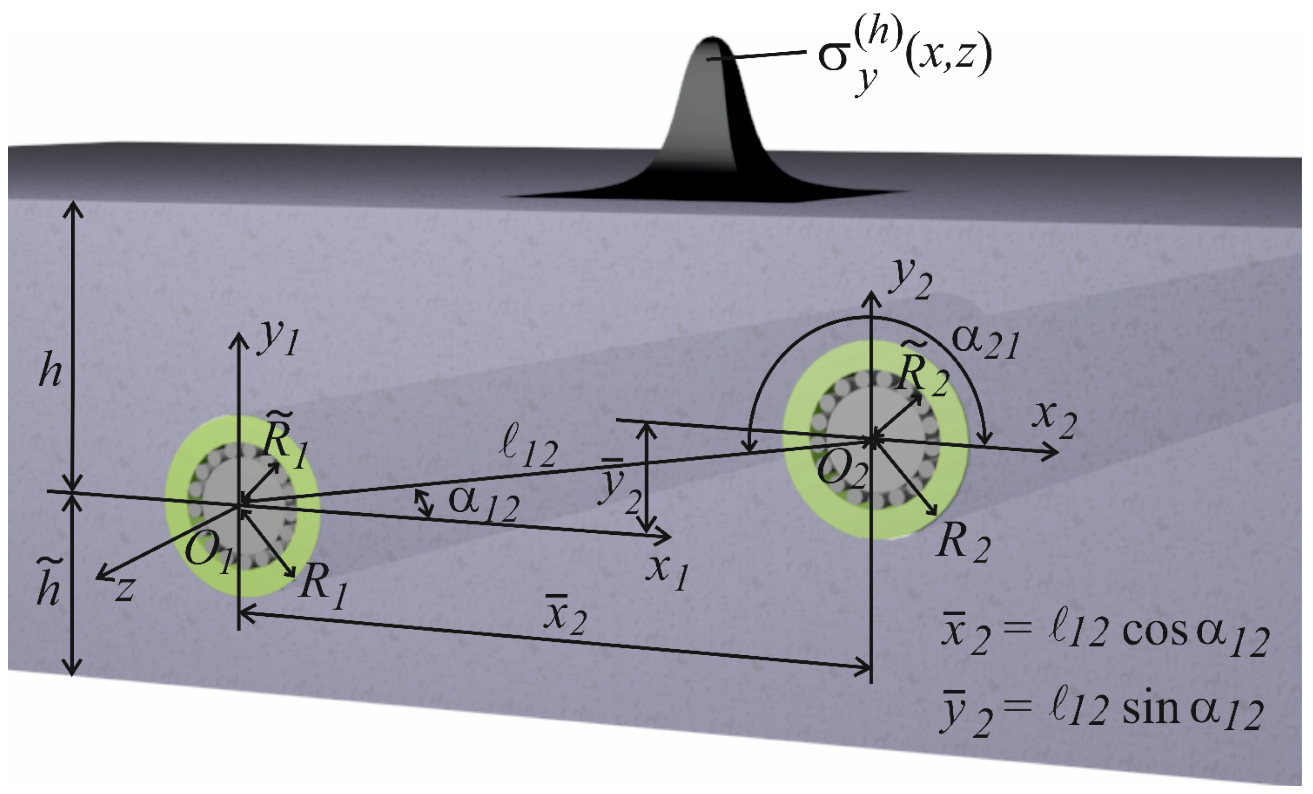
  • The development of a method for calculating the stress–strain state of a layer with two embedded cylindrical pipes, at given stresses on the flat surfaces of the layer and given contact-type conditions on the inner surfaces of the pipes.
  • The analysis of the stress state at different geometric characteristics and different pipe materials.

2. Materials and Methods

The model was considered in the form of an infinite elastic layer containing two infinite pipes parallel to each other and the boundaries of the layer (Figure 1). The pipes were considered in local cylindrical coordinate systems (ρp, φ p, z), p = 1, 2. The layer was considered in the Cartesian system (x, y, z).
The cylindrical coordinate system of the first pipe (ρ1, φ 1, z) is aligned and oriented equally with the Cartesian layer system (x1, y1, z).
Distance to the upper boundary of the layer y = h, and distance to the lower boundary of the layer y = h ~ . The second pipe is located relative to the first at a distance of ℓ12 and at an angle of α12.
The materials of the layer and pipes are elastic, homogeneous, and isotropic, with different physical and mechanical properties.
On the flat surfaces of the layer, the stresses F U x , z y = h = F h 0 x , z and F U x , z y = h ~ = F h ~ 0 x , z are given, where
F h 0 x , z = τ y x h e x + σ y h e y + τ y z h e z , F h ~ 0 x , z = τ y x h ~ e x + σ y h ~ e y + τ y z h ~ e z .
Frictionless rigid contact conditions (normal displacements and tangential stresses) are set on the inner surface of the pipes:
U ρ φ p , z ρ p = R p = U 0 p φ p , z , τ ρ φ ρ p = R p = τ 1 p φ p , z , τ ρ z ρ p = R p = τ 2 p φ p , z .
All specified functions are continuous and rapidly decreasing.
The most effective method for the high-precision determination of the stress–strain state of such a model is the generalized Fourier method with its application to the Lamé equations.
The basic solutions of the Lamé equation are chosen in the following form [15]:
u k ± x , y , z ; λ , μ = N k d e i λ z + μ x ± γ y ; R k , m ρ , φ , z ; λ = N k p I m λ ρ e i λ z + m φ ; S k , m ρ , φ , z ; λ = N k p sign   λ m K m λ ρ e i λ z + m φ ; k = 1 , 2 , 3 ;
N 1 d = 1 λ ; N 2 d = 4 λ ν 1 e 2 1 + 1 λ y ; N 3 d = i λ r o t e 3 1 ; N 1 p = 1 λ ;
N 2 p = 1 λ ρ ρ + 4 ν 1 e 3 2 z ; N 3 p = i λ rot   e 3 2 ; γ = λ 2 + μ 2 ;
< λ , μ < ,
where I m x and K m x are modified Bessel functions; ν is Poisson’s ratio; S k , m and R k , m , k = 1, 2, and 3, are the external and internal solutions of the Lamé equation for cylindrical surfaces, respectively; u k + is the solution of the Lamé equation for the Cartesian coordinate system at y < 0; and u k is the solution of the Lamé equation for the Cartesian coordinate system at y > 0.
To transfer these basic solutions between different coordinate systems, we used the transition formulas [15,16,21], which will be presented further in this text.
The distance and angle between the parallel displaced cavities are determined by the formulas [21].

3. Results

3.1. Creating and Solving a System of Equations

The solution to the problem is represented in the form
U 0 = k = 1 3 H k λ , μ u k + x , y , z ; λ , μ + H ~ k λ , μ u k x , y , z ; λ , μ d μ d λ + p = 1 2 k = 1 3 m = B k , m p λ S k , m ρ p , φ p , z ; λ d λ ,
U 1 = k = 1 3 m = A k , m 1 λ R k , m ρ 1 , φ 1 , z ; λ + A ~ k , m 1 λ S k , m ρ 1 , φ 1 , z ; λ d λ , U 2 = k = 1 3 m = A k , m 2 λ R k , m ρ 2 , φ 2 , z ; λ + A ~ k , m 2 λ S k , m ρ 2 , φ 2 , z ; λ d λ ,
where u k + , u k , S k , m , and R k , m are the basic solutions of (3); H k λ , μ , H ~ k λ , μ , B k , m 1 λ , B k , m 2 λ , A k , m 1 λ , A ~ k , m 1 λ , A k , m 2 λ , and A ~ k , m 2 λ are the unknown functions to be found.
To find the eight unknown solutions of (4) and (5), a system of eight integro-algebraic equations was formed.
The first two equations are obtained by satisfying the boundary conditions on the flat surfaces of the layer (1). To achieve this, the double Fourier integral [26] was applied to functions (1), after which it was substituted into the left side of (4), and the basic solutions S k , m from the cylindrical coordinate system were rewritten through u k ± into the Cartesian coordinates using the transition formulas [21].
S k , m ρ p , φ p , z ; λ = i m 2 ω m e i μ x ̄ p ± γ y ̄ p u k d μ γ ,   k = 1 ,   3 ; S 2 , m ρ p , φ p , z ; λ = i m 2 ω m ( ± m μ λ 2 γ ± λ 2 y ̄ p u 1 λ 2 u 2 ± ± 4 μ 1 ν u 3 ) e i μ x ̄ p ± γ y ̄ p d μ γ 2 ,
where γ = λ 2 + μ 2 , ω λ , μ = μ γ λ , and m = 0 , ± 1 , ± 2 , .
Two more equations are created when satisfying the boundary conditions on the inner surfaces of the tubes (2). To carry out this, an integral and a Fourier series are applied to the functions (2) and then substituted into the left side of (5).
Four additional equations are created when the conjugation conditions between the layer and each tube are satisfied.
U 0 φ , z ρ = R p = U p φ , z ρ = R p
F U 0 φ , z ρ = R p = F U p φ , z ρ = R p
where U 0 φ , z is the solution for the layer; U p φ , z is the solution for the pipes; and F U = 2 G ν 1 2 ν n div   U + n U + 1 2 n × rot   U is the stress operator.
Under conjugation conditions, the basis solutions u k ± are rewritten from the Cartesian coordinate system through R k , m in the local cylindrical coordinate system using the transition functions [21].
u k ± x , y , z = e i μ x ̄ p ± γ y ̄ p m = i ω m R k , m , k = 1 , 3 ; u 2 ± x , y , z = e i μ x ̄ p ± γ y ̄ p m = i ω m λ 2 m μ + y ̄ p λ 2 R 1 , m ± ± γ R 2 , m + 4 μ 1 ν R 3 , m ,
where R k , m = b ~ k , m ρ p , λ e i m ϕ p + λ z ; b ~ 1 , n ρ , λ = e ρ I n λ ρ + i I n λ ρ e ϕ n λ ρ + e z ;
b ~ 2 , n ρ , λ = e ρ 4 ν 3 I n λ ρ + λ ρ I n λ ρ + e φ i m I n λ ρ + 4 ν 1 λ ρ I n λ ρ + + e z i λ ρ I n λ ρ ;
and b ~ 3 , n ρ , λ = e ρ I n λ ρ n λ ρ + e φ i I n λ ρ ; e ρ , e φ , and e z are orts in the cylindrical coordinate system.
In addition, the formulas for the transition of basis solutions from one local cylindrical coordinate system to another are used [16].
S k , m ρ p , φ p , z ; λ = n = b k , p q m n ρ q e i n φ q + λ z , k = 1 ,   2 ,   3 ; b 1 , p q m n ρ q = 1 n K ~ m n λ l p q e i m n α p q b ~ 1 , n ρ q , λ ; b 3 , p q m n ρ q = 1 n K ~ m n λ l p q e i m n α p q b ~ 3 , n ρ q , λ ; b 2 , p q m n ρ q = 1 n K ~ m n λ l p q b ~ 2 , n ρ q , λ λ 2 l p q K ~ m n + 1 λ l p q + K ~ m n 1 λ l p q b ~ 1 , n ρ q , λ e i m n α p q ,
where α p q is the angle between the xp axis and the segment l q p , K ~ m x = s i g n x m K m x .
From the first two equations of the system (created by fulfilling the boundary conditions on the flat surfaces of the layer), the following were expressed, H k λ , μ and H ~ k λ , μ , through B k , m p λ and then were substituted into the last four. Having freed ourselves from series and integrals on the left and right sides, we obtained an infinite system of six linear algebraic equations of the second kind to which the method of reduction can be applied. As a result of the solution, we found the unknowns B k , m 1 λ , B k , m 2 λ , A k , m 1 λ , A ~ k , m 1 λ , A k , m 2 λ , and A ~ k , m 2 λ . The functions B k , m 1 λ and B k , m 2 λ are substituted into the expression for H k λ , μ and H ~ k λ , μ . As a result, all unknowns were found.

3.2. Numerical Analysis of the Stress State of the Layer and Pipes

The problem is solved for a layer with two cylindrical pipes (Figure 1). The pipes are located on the same horizontal axis (α12 = 0). The distance between the pipes was calculated in two variants, ℓ12 = 50 mm and ℓ12 = 100 mm.
Layer material: aluminum alloy D16T, modulus of elasticity E0 = 7.1·104 MPa, Poisson’s ratio ν0 = 0.3. Pipe material: steel, modulus of elasticity E1 = E2 = 2.16·105 MPa, Poisson’s ratio ν1 = ν2 = 0.28. For comparison, we calculated a variant with a plastic pipe material of elastic modulus E1 = E2 = 1.7·103 MPa, Poisson’s ratio ν1 = ν2 = 0.38, and a variant with cavities instead of pipes [22], with a cavity radius of R ~ 1 = R ~ 2 = 11   mm.
The outer radius of the pipes R1 = R2 = 16 mm, and the inner radius R ~ 1 = R ~ 2 = 11 mm. Distance from the center of the pipes to the upper and lower boundaries of the layer h = h ~ = 32 mm.
At the upper boundary of the layer, in the middle between the pipes, the stresses are set in the form of a wave of normal stresses σ y h x , z = 1 0 8 z 2 + 1 0 2 2 x 2 + 1 0 2 2 (graphically, this function is shown in Figure 1) and τ y x h x , z = τ y z h x , z = 0 . There are no stresses at the lower boundary of the layer σ y h ~ x , z = τ y x h ~ x , z = τ y z h ~ x , z = 0 . Frictionless rigid contact conditions are set on the inner surfaces of the pipes, U 0 p φ p , z = 0 and τ 1 p φ p , z = τ 2 p φ p , z = 0 .
The infinite system of equations was reduced to m = 5. With the given geometric parameters, this allowed us to obtain the fulfillment of the boundary conditions with an accuracy of 10−6 for values from zero to one.
Depending on the distance between the supports, stresses σ ρ occur on the inner surface of the pipe and at the joint between the pipe and the layer (Figure 2).
The stresses σ ρ on the left support (Figure 2) are concentrated in the right part (closer to the load), which is quite logical. The upper right part of the body near the left support is compressed, and the lower right part is stretched.
As the distance between the supports decreases, the stresses σ ρ increase. This is due to the fact that as the supports come closer together, the load also comes closer to the supports.
The stresses σ ρ at the interface are reduced compared to the inner surface of the pipes.
Therefore, the maximum stresses σ ρ occur on the inner surface of the pipe with a minimum distance between the supports (Figure 2).
Compared to the variant when instead of a pipe there is only a cavity with a radius of R1, the stresses σ ρ are almost the same.
The stresses σ φ on the inner surface of the pipe and at the junction between the pipe and the layer (in the body of the layer) are shown in Figure 3.
The stresses σ φ on the left support (Figure 3), similar to the stress σ ρ , are concentrated in the right part. The upper right part of the bodies near the left support on the surface of the pipe is stretched; on the surface of the interface between the layer and the pipe, it is compressed, and the lower right part of the bodies is compressed.
As the distance between the supports decreases, the stresses σ φ increase.
The stresses σ φ at the interface in the body of the layer, compared to the inner surface of the pipes, decrease and are constantly negative.
If instead of a pipe there is only a cavity with a radius of R1, the stresses σ φ are reduced.
The maximum stresses σ φ occur on the inner surface of the pipe at the minimum distance between the supports (Figure 3) and are positive.
The stresses σ ρ on the right support are symmetrical to Figure 2, and the stresses σ φ on the right support are symmetrical to Figure 3.
Changing the material of cylindrical pipes to plastic changes the stress state on the inner surface of the pipe. Figure 4 shows the stresses σ ρ on the inner surface of the pipe at L12 = 50 mm depending on the material.
The use of a material with weakened physical and mechanical characteristics reduces the stress σ ρ on the inner surface of the pipe (Figure 4). The nature of the stress lines σ ρ remains almost unchanged. Only the places of maximum positive and negative stresses shift slightly.
The stress σ φ on the inner surface of the pipe also decreases significantly with the change in pipe material to plastic.
As for the stress state of the layer in the zone of its cylindrical conjugation with the pipe, the stress in this zone increases significantly with the change in pipe material to plastic.
Figure 5 shows the stresses σ φ in the body of the layer on a cylindrical surface that is rigidly conjugated to a pipe, p = 1.
When the pipe material is changed to plastic, the stresses σ φ on the interface in the body of the layer increase significantly (Figure 5). The nature of the stress state also changes: at some φ, the stress changes its sign to the opposite.
The maximum negative values of σ φ = –0.18265 MPa occur at φ = 0, and the maximum positive values of σ φ = 0.15611 MPa occur at φ = π/3.
The stresses σ z in the body of the layer on a cylindrical surface rigidly conjugated to a pipe, p = 1, are shown in Figure 6.
Stresses σ z in the body of the layer on the surface of the mating with the pipe are concentrated in the upper part of the cylindrical joint (Figure 6). The sign of the numerical values of the stresses σ z depends on the selected pipe material. If the pipe is made of steel, the stresses in the body of the layer are compressive, and if the pipe is made of plastic, they are tensile.
The maximum stress values of σ z do not lie on the vertical axis, but are shifted in the direction of the load located on the right. The same mirror effect is observed for the right support.

4. Discussion

An analytical and numerical method for solving the spatial problem of the theory of elasticity for a layer on two embedded hinged supports with cylindrical gaskets (bearings) is developed. Stresses are set on the flat surfaces of the layer, and contact-type conditions are set on the inner surfaces of the pipes.
The presented method is an extension of [16,17,18,19,20,21,22,23,24,25].
Thus, in comparison with works [16,17,18,19], the proposed method allows us to obtain the stress–strain state for a layer with cylindrical inclusions and takes into account the contact-type conditions (for a bearing).
Compared to [20,21,22], the present work takes into account the conditions of conjugation between bodies, which allows for solving problems for a layer with inclusions.
In contrast to [23], the proposed approach makes it possible to consider more than one inclusion and an inclusion can have more than one upper boundary.
Compared to [24], the bearing is presented in the present work as a thick-walled pipe, which is more consistent with the structure of the bearing connection.
In contrast to [25], the proposed method allows us to consider two pipes and take into account the conditions of the contact type.
Using the generalized Fourier method, a high-precision stress–strain state of the layer body and pipes was obtained.
The stress–strain analysis showed that
1.
Due to the specified frictionless rigid contact conditions on the supports, there is no moment, and therefore no tangential stress on the supports. This corresponds to physical laws and the results of solving elementary problems of structural mechanics. The boundary conditions are fulfilled with high accuracy, which increases with the order of the system of equations. The comparison of some results with [22,24,25] adds confidence in the reliability of the results obtained.
2.
If instead of a pipe there is a cavity with radius R1, it does not affect the stress σ ρ but significantly affects other stresses. Thus, the stresses σ φ , in the presence of a pipe, increase by almost 50%, and the stresses σ z decrease by five times.
3.
Increasing the distance between the supports reduces the stress in the support zone.
4.
Changing the material of the pipe significantly affects the stress state of the layer in the zone of the pipe–layer interface. Thus, the stresses σ ρ increase significantly if the pipe material is steel, and the stresses σ φ and σ z decrease, changing the sign to the opposite.
The conclusions from the stress–strain analysis allow for a more efficient preliminary determination of the geometric parameters of the model and joint materials during design.
The proposed solution method can be used to determine the stress state of a layer with bearings or a layer with bushings.
Further research into this problem would be interesting in the presence of an additional stress concentrator in the form of a cavity or inclusion (reinforcement).

Author Contributions

Conceptualization, V.M. and O.D.; methodology, O.S.; software, O.S.; validation, I.G. and O.S.; formal analysis, O.D.; resources, I.G.; data curation, I.G.; writing—original draft preparation, O.D.; writing—review and editing, V.M.; visualization, O.S.; project administration, V.M. All authors have read and agreed to the published version of the manuscript.

Funding

This research received no external funding.

Data Availability Statement

The original contributions presented in the study are included in the article, further inquiries can be directed to the corresponding author.

Conflicts of Interest

The authors declare no conflicts of interest.

References

  1. Aitharaju, V.; Aashat, S.; Kia, H.; Satyanarayana, A.; Bogert, P. Progressive Damage Modeling of Notched Composites. NASA Technical Reports Server. Available online: https://ntrs.nasa.gov/archive/nasa/casi.ntrs.nasa.gov/20160012242.pdf (accessed on 16 June 2024).
  2. Kondratiev, A.V.; Gaidachuk, V.E.; Kharchenko, M.E. Relationships Between the Ultimate Strengths of Polymer Composites in Static Bending, Compression, and Tension. Mech. Compos. Mater. 2019, 55, 259–266. [Google Scholar] [CrossRef]
  3. Tekkaya, A.E.; Soyarslan, C. Finite Element Method. In Encyclopedia of Production Engineering; Springer: Berlin, Germany, 2014; pp. 508–514. [Google Scholar]
  4. Static Structural Simulation Using Ansys Discovery. Available online: https://courses.ansys.com/index.php/courses/structural-simulation (accessed on 16 June 2024).
  5. Zasovenko, A.; Fasoliak, A. Mathematical modeling of the dynamics of an elastic half-medium with a cylindrical cavity reinforced by a shell under axisymmetric loads. In New Materials and Technologies in Metallurgy and Mechanical Engineering; Trans Tech Publications Ltd.: Wollerau, Switzerland, 2023; Volume 2, pp. 67–73. [Google Scholar]
  6. Azarov, A.D.; Zhuravlev, H.A.; Pyskunov, A.S. Comparative analysis of analytical and numerical methods for solving the plane problem of contact of elastic cylinders. Innov. Nauka 2015, 1–2, 5–13. [Google Scholar]
  7. Huz, A.N.; Kubenko, V.D.; Cherevko, M.A. Dyfraktsyia Upruhykh Voln [Elastic Wave Diffraction]; Naukova Dumka: Kyiv, Ukraine, 1978; pp. 14–194. [Google Scholar]
  8. Grinchenko, V.T.; Meleshko, V.V. Garmonicheskiye Kolebaniya i volny v Uprugikh Telakh; Naukova Dumka: Kyiv, Ukraine, 1981; pp. 15–284. [Google Scholar]
  9. Fesenko, A.; Vaysfel’d, N. The Wave Field of a Layer with a Cylindrical Cavity. In Proceedings of the Second International Conference on Theoretical, Applied and Experimental Mechanics, ICTAEM 2019, Corfu, Greece, 23–26 June 2019; Gdoutos, E., Ed.; Structural Integrity. Springer: Berlin/Heidelberg, Germany, 2019; Volume 8, pp. 277–282. [Google Scholar]
  10. Fesenko, A.; Vaysfel’d, N. The dynamical problem for the infinite elastic layer with a cylindrical cavity. Procedia Struct. Integr. 2021, 33, 509–527. [Google Scholar] [CrossRef]
  11. Ugrimov, S.; Smetankina, N.; Kravchenko, O.; Yareshchenko, V. Analysis of Laminated Composites Subjected to Impact. In Proceedings of the ICTM 2020: Integrated Computer Technologies in Mechanical Engineering-2020; Lecture Notes in Networks and Systems. Springer: Kharkiv, Ukraine, 2021; Volume 188, pp. 234–246. [Google Scholar] [CrossRef]
  12. Rodichev, Y.M.; Smetankina, N.V.; Shupikov, O.M.; Ugrimov, S.V. Stress-Strain Assessment for Laminated Aircraft Cockpit Windows at Static and Dynamic Load. Strength Mater. 2018, 50, 868–873. [Google Scholar] [CrossRef]
  13. Jafari, M.; Chaleshtari, M.H.B.; Khoramishad, H.; Altenbach, H. Minimization of thermal stress in perforated composite plate using metaheuristic algorithms WOA, SCA and GA. Compos. Struct. 2022, 304, 116403. [Google Scholar] [CrossRef]
  14. Khechai, A.; Belarbi, M.O.; Bouaziz, A.; Rekbi, F.M.L. A general analytical solution of stresses around circular holes in functionally graded plates under various in-plane loading conditions. Acta Mech. 2023, 234, 671–691. [Google Scholar] [CrossRef]
  15. Nikolayev, A.G.; Protsenko, V.S. Obobshchennyy metod Furʹye v Prostranstvennykh Zadachakh Teorii Uprugosti; Nats. Aerokosm. Universitet im. N.Ye. Zhukovskogo “KHAI”: Kharʹkov, Ukraine, 2011; pp. 10–344. [Google Scholar]
  16. Nikolaev, A.G.; Tanchik, E.A. The first boundary-value problem of the elasticity theory for a cylinder with N cylindrical cavities. Numer. Anal. Appl. 2015, 8, 148–158. [Google Scholar] [CrossRef]
  17. Nikolaev, A.G.; Tanchik, E.A. Stresses in an elastic cylinder with cylindrical cavities forming a hexagonal structure. J. Appl. Mech. Tech. Phys. 2016, 57, 1141–1149. [Google Scholar] [CrossRef]
  18. Nikolaev, A.G.; Tanchik, E.A. Model of the Stress State of a Unidirectional Composite with Cylindrical Fibers Forming a Tetragonal Structure. Mech. Compos. Mater. 2016, 52, 177–188. [Google Scholar] [CrossRef]
  19. Ukrayinets, N.; Murahovska, O.; Prokhorova, O. Solving a one mixed problem in elasticity theory for half-space with a cylindrical cavity by the generalized fourier method. East.-Eur. J. Enterp. Technol. 2021, 2, 48–57. [Google Scholar] [CrossRef]
  20. Protsenko, V.; Miroshnikov, V. Investigating a problem from the theory of elasticity for a half-space with cylindrical cavities for which boundary conditions of contact type are assigned. East.-Eur. J. Enterp. Technol. 2018, 4, 43–50. [Google Scholar] [CrossRef]
  21. Miroshnikov, V.; Younis, B.; Savin, O.; Sobol, V. A Linear elasticity theory to analyze the stress state of an infinite layer with a cylindrical cavity under periodic loading. Computation 2022, 10, 160. [Google Scholar] [CrossRef]
  22. Miroshnikov, V.; Savin, O.; Sobol, V.; Nikichanov, V. Solving the Problem of Elasticity for a Layer with N Cylindrical Embedded Supports. Computation 2023, 11, 172. [Google Scholar] [CrossRef]
  23. Miroshnikov, V.Y.; Medvedeva, A.V.; Oleshkevich, S.V. Determination of the Stress State of the Layer with a Cylindrical Elastic Inclusion. 6th International Conference “Actual Problems of Engineering Mechanics” (APEM 2019). Mater. Sci. Forum 2019, 968, 413–420. [Google Scholar] [CrossRef]
  24. Miroshnikov, V.; Savin, O.; Younis, B.; Nikichanov, V. Solution of the Problem of the Theory of Elasticity and Analysis of the Stress State of a Fibrous Composite Layer Under the Action of Transverse Compressive Forces. East.-Eur. J. Enterp. Technol. 2022, 4, 23–30. [Google Scholar] [CrossRef]
  25. Vitaly, M. Rotation of the Layer with the Cylindrical Pipe around the Rigid Cylinder. In Advances in Mechanical and Power Engineering; CAMPE 2021; Lecture Notes in Mechanical Engineering; Springer: Cham, Switzerland, 2023; pp. 314–322. [Google Scholar] [CrossRef]
  26. Singh, P.; Gupta, A.; Joshi, S.D. General Parameterized Fourier Transform: A Unified Framework for the Fourier, Laplace, Mellin and Z Transforms. IEEE Trans. Signal Process. 2022, 70, 1295–1309. [Google Scholar] [CrossRef]
Figure 1. A layer with two cylindrical tubes.
Computation 12 00182 g001
Figure 2. Stresses of σ ρ on the left support (p = 1).
Computation 12 00182 g002
Figure 3. Stresses of σ ρ on the left support (p = 1).
Computation 12 00182 g003
Figure 4. Stresses of σ ρ on the left support (p = 1).
Computation 12 00182 g004
Figure 5. Stresses σ φ in the body of the layer at the interface with the pipe, p = 1.
Computation 12 00182 g005
Figure 6. Stresses σ z in the body of the layer at the interface with the pipe, p = 1.
Computation 12 00182 g006
Disclaimer/Publisher’s Note: The statements, opinions and data contained in all publications are solely those of the individual author(s) and contributor(s) and not of MDPI and/or the editor(s). MDPI and/or the editor(s) disclaim responsibility for any injury to people or property resulting from any ideas, methods, instructions or products referred to in the content.

