
Biomechanical Effects of Ti-Base Abutment Height on the Dental Implant System: A Finite Element Analysis

 , , , ,
  and
and 
Abstract
:1. Introduction
2. Materials and Methods
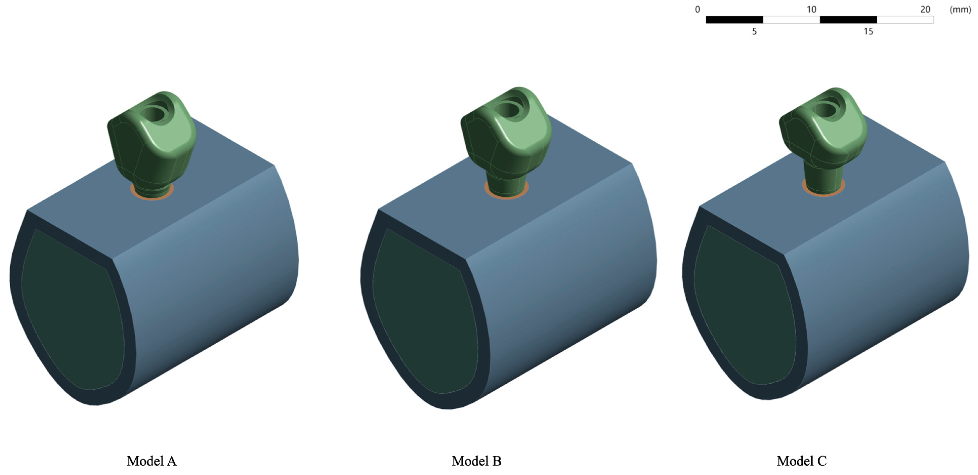
2.1. Finite Element Model Design
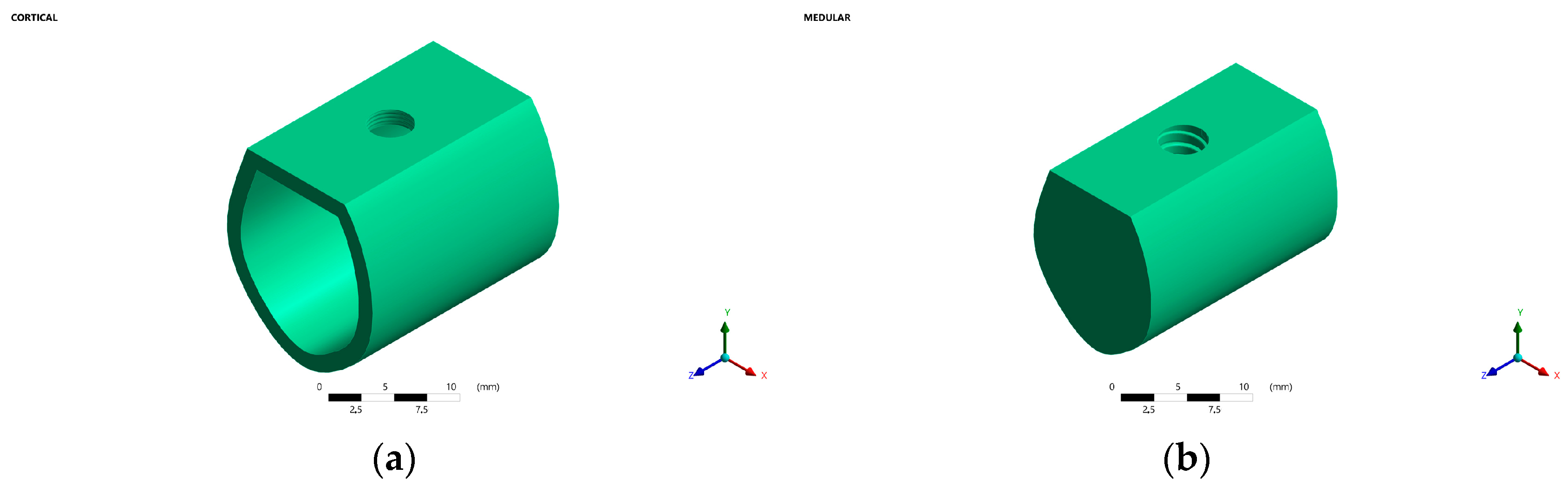
2.1.1. Bone
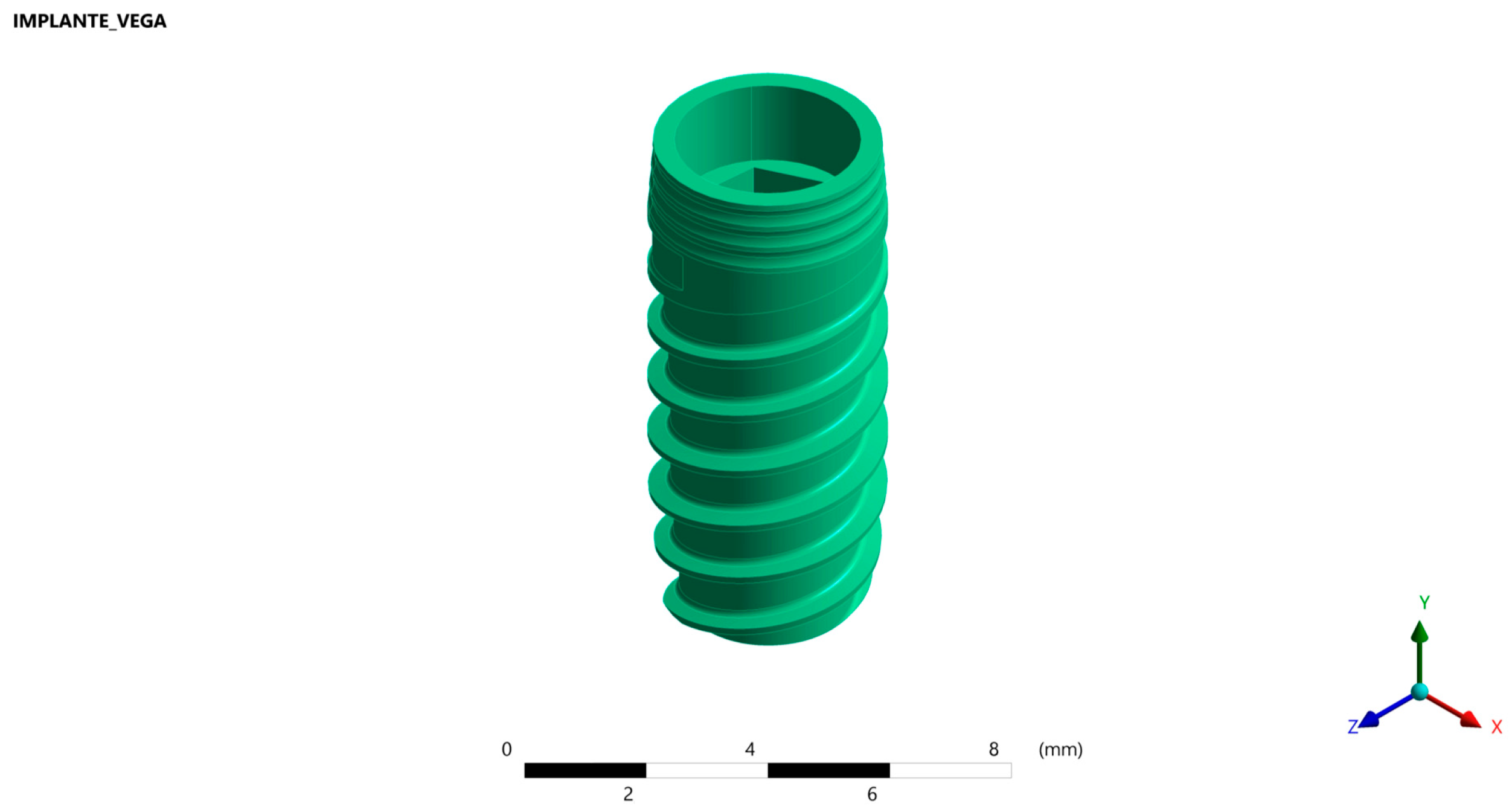
2.1.2. Implant
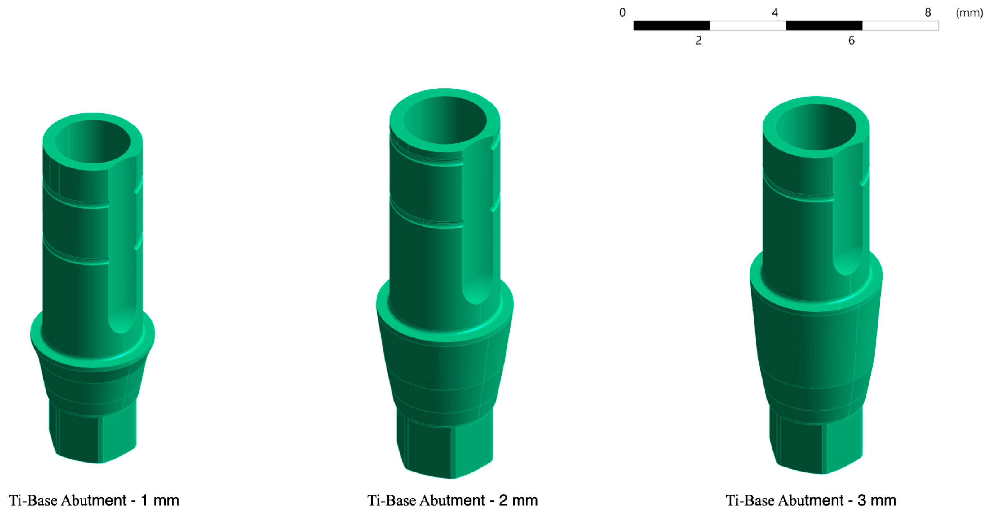
2.1.3. Ti-Base Abutment
2.1.4. Prosthetic Crown
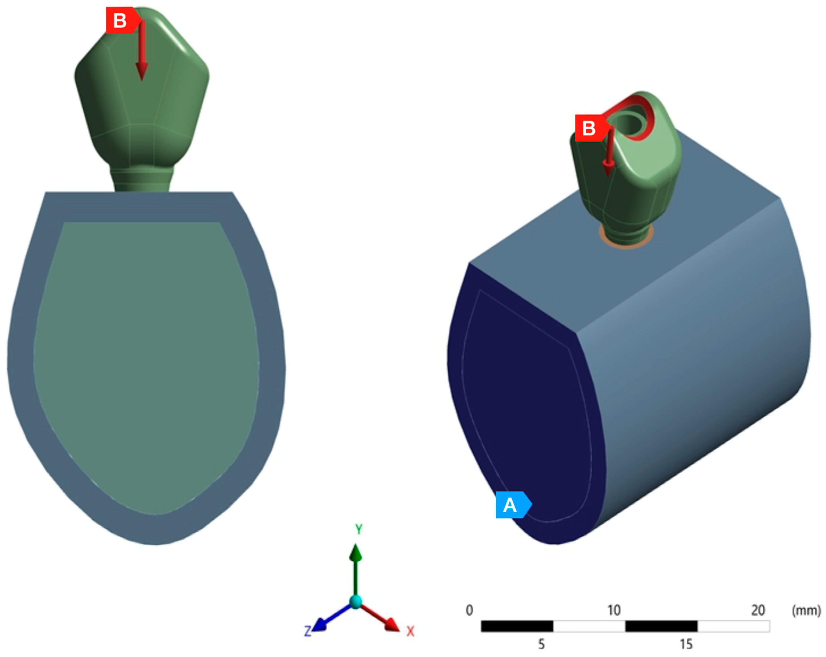
2.2. Material Properties, Interface Conditions, Load and Boundary Conditions
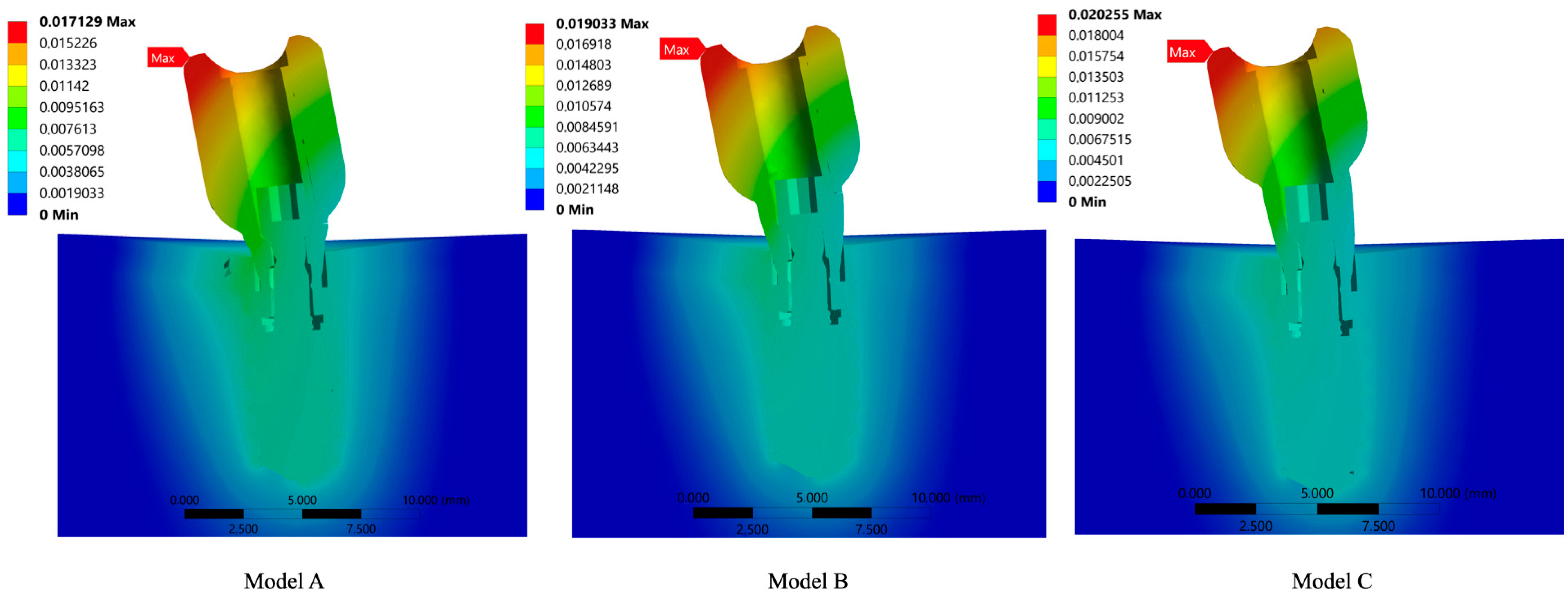
3. Results
4. Discussion
5. Conclusions
Author Contributions
Funding
Data Availability Statement
Acknowledgments
Conflicts of Interest
References
- Kurbad, A.; Kurbad, S. CAD/CAM-based implant abutments. Int. J. Comput. Dent. 2013, 16, 125–141. [Google Scholar] [PubMed]
- Silva, C.E.P.; Soares, S.; Machado, C.M.; Bergamo, E.T.P.; Coelho, P.G.; Witek, L.; Ramalho, I.S.; Jalkh, E.B.B.; Bonfante, E.A. Effect of CAD/CAM Abutment Height and Cement Type on the Retention of Zirconia Crowns. Implant Dent. 2018, 27, 582–587. [Google Scholar] [CrossRef]
- Galindo-Moreno, P.; León-Cano, A.; Ortega-Oller, I.; Monje, A.; Suárez, F.; ÓValle, F.; Spinato, S.; Catena, A. Prosthetic Abutment Height is a Key Factor in Peri-implant Marginal Bone Loss. J. Dent. Res. 2014, 93, 80S–85S. [Google Scholar] [CrossRef] [PubMed]
- Chen, Z.; Lin, C.Y.; Li, J.; Wang, H.L.; Yu, H. Influence of abutment height on peri-implant marginal bone loss: A systematic review and meta-analysis. J. Prosthet. Dent. 2019, 122, 14–21.e2. [Google Scholar] [CrossRef] [PubMed]
- Verma, A.; Singh, S.V.; Arya, D.; Shivakumar, S.; Chand, P. Mechanical failures of dental implants and supported prostheses: A systematic review. J. Oral Biol. Craniofacial Res. 2023, 13, 306–314. [Google Scholar] [CrossRef] [PubMed]
- Schwarz, F.; Ramanauskaite, A. It is all about peri-implant tissue health. Periodontol. 2000 2022, 88, 9–12. [Google Scholar] [CrossRef] [PubMed]
- Albrektsson, T.; Zarb, G.; Worthington, P.; Eriksson, A.R. The long-term efficacy of currently used dental implants: A review and proposed criteria of success. Int. J. Oral Maxillofac. Implant. 1986, 1, 11–25. [Google Scholar]
- Frost, H.M. Wolff’s law and bone’s structural adaptations to mechanical usage: An overview for clinicians. Angle Orthod. 1994, 64, 175–188. [Google Scholar]
- Cerrolaza, M. El Método de los Elementos Finitos para Ingeniería y Ciencias Aplicadas: Teoría y Programas; Consejo de Desarrollo Científico y Humanístico, UCV: Caracas, Venezuela, 2006. [Google Scholar]
- Geng, J.P.; Tan, K.B.; Liu, G.R. Application of finite element analysis in implant dentistry: A review of the literature. J. Prosthet. Dent. 2001, 85, 585–598. [Google Scholar] [CrossRef]
- Falcinelli, C.; Valente, F.; Vasta, M.; Traini, T. Finite element analysis in implant dentistry: State of the art and future directions. Dent. Mater. 2023, 39, 539–556. [Google Scholar] [CrossRef]
- Elleuch, S.; Jrad, H.; Wali, M.; Dammak, F. Finite element analysis of the effect of porosity on biomechanical behaviour of functionally graded dental implant. Proc. Inst. Mech. Eng. Part E J. Process Mech. Eng. 2023. [Google Scholar] [CrossRef]
- Meijer, H.J.; Starmans, F.J.; Steen, W.H.; Bosman, F. A three-dimensional, finite-element analysis of bone around dental implants in an edentulous human mandible. Arch. Oral Biol. 1993, 38, 491–496. [Google Scholar] [CrossRef] [PubMed]
- Noureddine, D.; Bachiri, A.; Boutabout, B. Comparison of stress distribution in surrounding bone during insertion of dental implants on four implant threads under the effect of an impact: A finite element study. J. Biomim. Biomater. Biomed. Eng. 2022, 54, 89–101. [Google Scholar]
- Lekholm, U.; Zarb, G.A.; Albrektsson, T. Patient Selection and Preparation. Tissue Integrated Prostheses; Quintessence Publishing Co., Inc.: Chicago, IL, USA, 1985; pp. 199–209. [Google Scholar]
- Teixeira, E.R.; Sato, Y.; Akagawa, Y.; Shindoi, N. A comparative evaluation of mandibular finite element models with different lengths and elements for implant biomechanics. J. Oral Rehabil. 1998, 25, 299–303. [Google Scholar] [CrossRef] [PubMed]
- Sabeva, E.; Peev, S.; Miteva, M.; Georgieva, M. Bone characteristics and implant stability. Scr. Sci. Med. Dent. 2017, 3, 18–22. [Google Scholar] [CrossRef]
- Sabri, L.A.; Hussein, F.A.; Al-Zahawi, A.R.; Abdulrahman, B.Y.; Salloomi, K.N. Biomechanical finite element analysis of a single implant threaded in anterior and posterior regions of maxilla bone. Indian J. Dent. Res. 2020, 31, 203–208. [Google Scholar] [CrossRef]
- Oliveira, H.; Brizuela Velasco, A.; Ríos-Santos, J.V.; Sánchez Lasheras, F.; Lemos, B.F.; Gil, F.J.; Carvalho, A.; Herrero-Climent, M. Effect of Different Implant Designs on Strain and Stress Distribution under Non-Axial Loading: A Three-Dimensional Finite Element Analysis. Int. J. Environ. Res. Public. Health 2020, 17, 4738. [Google Scholar] [CrossRef]
- Ekici, B. Numerical analysis of a dental implant system in three-dimension. Adv. Eng. Softw. 2002, 33, 109–113. [Google Scholar] [CrossRef]
- Nagasao, T.; Kobayashi, M.; Tsuchiya, Y.; Kaneko, T.; Nakajima, T. Finite element analysis of the stresses around fixtures in various reconstructed mandibular models—Part II (effect of horizontal load). J. Craniomaxillofac. Surg. 2003, 31, 168–175. [Google Scholar] [CrossRef]
- Menacho-Mendoza, E.; Cedamanos-Cuenca, R.; Díaz-Suyo, A. Stress analysis and factor of safety in three dental implant systems by finite element analysis. Saudi Dent. J. 2022, 34, 579–584. [Google Scholar] [CrossRef]
- Nokar, S.; Jalali, H.; Nozari, F.; Arshad, M. Finite Element Analysis of Stress in Bone and Abutment-Implant Interface under Static and Cyclic Loadings. Front. Dent. 2020, 17, 21. [Google Scholar] [CrossRef] [PubMed]
- Ihde, S.; Goldmann, T.; Himmvola, L.; Aleksic, Z. The use of finite element analysis to model bone-implant contact with basal implants. Oral Surg. Oral Med. Oral Pathol. Oral Radiol. Endod. 2008, 106, 863–872. [Google Scholar] [CrossRef] [PubMed]
- Sugiura, T.; Yamamoto, K.; Horita, S.; Murakami, K.; Tsutsumi, S.; Kirita, T. The efects of bone density and crestal cortical bone thickness on micromotion and peri-implant bone strain distribution in an immediately loaded implant: A nonlinear finite element analysis. J. Periodontal. Implant Sci. 2016, 46, 152–165. [Google Scholar] [CrossRef] [PubMed]
- Borchers, L.; Reichart, P. Three-dimensional stress distribution around a dental implant at different stages of interface development. J. Dent. Res. 1983, 62, 155–159. [Google Scholar] [CrossRef]
- Ding, X.; Zhu, X.H.; Liao, S.H.; Zhang, X.H.; Chen, H. Implant-bone interface stress distribution in immediately loaded implants of di_erent diameters: A three-dimensional finite element analysis. J. Prosthodont. 2009, 18, 393–402. [Google Scholar] [CrossRef] [PubMed]
- Dávila, E.; Ortiz-Hernández, M.; Perez, R.A.; Herrero-Climent, M.; Cerrolaza, M.; Gil, F.J. Crestal module design optimization of dental implants: Finite element analysis and in vivo studies. J. Mater. Sci. Mater. Med. 2019, 30, 90. [Google Scholar] [CrossRef] [PubMed]
- Watanabe, M.; Hattori, Y.; Satoh, C. Biological and biomechanical perspectives of normal dental oclusion. Int. Congr. Ser. 2005, 1284, 21–27. [Google Scholar] [CrossRef]
- Curtis, D.A.; Sharma, A.; Finzen, F.C.; Kao, T.R. Occlusal considerations for implant restorations in the partially edentolous Patient. J. Calif. Dent. Assoc. 2000, 28, 771–779. [Google Scholar] [PubMed]
- Sahin, S.; Sehreli, M.C.; Yalcin, E. The influence of functional forces on the biomechanics of implant supported prostheses—A review. J. Dent. 2002, 30, 271–282. [Google Scholar] [CrossRef]
- Munro, R.G. Elastic Moduli Data for Polycrystalline Ceramics; NISTIR 6853; National Institute of Standards and Technology: Gaithersburg, MD, USA, 2002. [Google Scholar]
- Frost, H.M. Bone mass and the mechanostat: A proposal. Anat. Rec. 1987, 219, 1–9. [Google Scholar] [CrossRef]
- Prados-Privado, M.; Martínez-Martínez, C.; Gehrke, S.A.; Prados-Frutos, J.C. Influence of Bone Definition and Finite Element Parameters in Bone and Dental Implants Stress: A Literature Review. Biology 2020, 9, 224. [Google Scholar] [CrossRef]
- Mendez, A.; Coronado, H. Stress in an implant-supported unitary fixed partial prosthesis with different materials in the first lower premolar through finite elements. Rev. Científica Odontol. 2023, 11, e140. (In Spanish) [Google Scholar]
- Pérez-Pevida, E.; Brizuela-Velasco, A.; Chávarri-Prado, D.; Jiménez-Garrudo, A.; Sánchez-Lasheras, F.; Solaberrieta-Méndez, E.; Diéguez-Pereira, M.; Fernández-González, F.J.; Dehesa-Ibarra, B.; Monticelli, F. Biomechanical Consequences of the Elastic Properties of Dental Implant Alloys on the Supporting Bone: Finite Element Analysis. Biomed Res. Int. 2016, 2016, 1850401. [Google Scholar] [CrossRef] [PubMed]
- Meijer, H.J.; Starmans, F.J.; Bosman, F.; Steen, W.H. A comparison of three finite element models of an edentulous mandible provided with implants. J. Oral Rehabil. 1993, 20, 147–157. [Google Scholar] [CrossRef]
- Cochran, D.L.; Hermann, J.S.; Schenk, R.K.; Higginbottom, F.L.; Buser, D. Biologic width around titanium implants. A histometric analysis of the implanto-gingival junction around unloaded and loaded nonsubmerged implants in the canine mandible. J. Periodontol. 1997, 68, 186–198. [Google Scholar] [CrossRef] [PubMed]
- Alvarez-Arenal, A.; Sgura-Mori, L.; Gonzalez-Gonzalez, I.; Gago, A. Stress distribution in the abutment and retention screw of a single implant supporting a prosthesis with platform switching. Int. J. Oral Maxillofac. Implant 2013, 28, e112–e121. [Google Scholar] [CrossRef] [PubMed]
- Papavasiliou, G.; Kamposiora, P.; Bayne, S.C.; Felton, D.A. Three-dimensional finite element analysis of stress- distribution around single tooth implants as a function of bony support, prosthesis type, and loading during function. J. Prosthet. Dent. 1996, 76, 633–640. [Google Scholar] [CrossRef]
- Kitamura, E.; Stegaroiu, R.; Nomura, S.; Miyakawa, O. Influence of marginal bone resorption on stress around an implant—A three-dimensional finite element analysis. J. Oral Rehabil. 2005, 32, 279–286. [Google Scholar] [CrossRef] [PubMed]
- Elleuch, S.; Jrad, H.; Kessentini, A.; Wali, M.; Dammak, F. Design optimization of implant geometrical characteristics enhancing primary stability using FEA of stress distribution around dental prosthesis. Comput. Methods Biomech. Biomed. Eng. 2021, 24, 1035–1051. [Google Scholar] [CrossRef] [PubMed]
- Brunski, J.B.; Puleo, D.A.; Nanci, A. Biomaterials and biomechanics of oral and maxillofacial implants: Current status and future developments. Int. J. Oral Maxillofac. Implant 2000, 15, 15–46. [Google Scholar]
- López, C.I.; Laguado, L.A.; Forero, L.E. Evaluación mecánica sobre el efecto de cargas oclusales en la conexión interfaz ósea, comparando 4 diseños de implantes para carga inmediata en aleaciones Ti6Al4V y TiNbZr (Tiadyne™) por análisis de elementos finitos. Rev. Latinoam. Metal. Mater. 2009, 1, 47–54. [Google Scholar]
- Mohanty, A.K.; Varghese, T.; Bhushan, P.; Mahapatro, R.K.; Kashi, A.B.; Kariyatty, P. Influence of Occlusal Stress on Implant Abutment Junction and Implant Bone Interface: A Finite Element Analysis Study. J. Contemp. Dent. Pract. 2022, 23, 1190–1194. [Google Scholar]
- Duyck, J.; Rønold, H.J.; Van Oosterwyck, H.; Naert, I.; Vander Sloten, J.; Ellingsen, J.E. The influence of static and dynamic loading on marginal bone reactions around osseointegrated implants: An animal experimental study. Clin. Oral Implants Res. 2001, 12, 207–218. [Google Scholar] [CrossRef] [PubMed]
- De Oliveira Rigotti, R.L.; Tardelli, J.D.C.; Dos Reis, A.C.; Da Valente, M.L.C. Influence of dental implant/mini-implant design on stress distribution in overdentures: A systematic review. In Oral and Maxillofacial Surgery; Springer: Berlin/Heidelberg, Germany, 2023. [Google Scholar]
- Linkevicius, T.; Apse, P.; Grybauskas, S.; Puisys, A. Reaction of crestal bone around implants depending on mucosal tissue thick- ness. A 1-year prospective clinical study. Stomatologija 2009, 11, 83–91. [Google Scholar] [PubMed]
- Linkevicius, T.; Apse, P.; Grybauskas, S.; Puisys, A. Influence of thin mucosal tissues on crestal bone stability around implants with platform switching: A 1-year pilot study. J. Oral Maxillofac. Surg. 2010, 68, 2272–2277. [Google Scholar] [CrossRef] [PubMed]
- Ellendula, Y.; Chandra Sekar, A.; Nalla, S.; Basany, R.B.; Sailasri, K.; Thandu, A. Biomechanical Evaluation of Stress Distribution in Equicrestal and Sub-crestally Placed, Platform-Switched Morse Taper Dental Implants in D3 Bone: Finite Element Analysis. Cureus 2022, 14, e24591. [Google Scholar] [CrossRef] [PubMed]
- Wang, T.M.; Leu, L.J.; Wang, J.S.; Lin, L.D. Effects of prosthesis materials and prosthesis splinting on peri-implant bone stress around implants in poor- quality bone: A numeric analysis. Int. J. Oral Maxillofac. Implants 2002, 17, 231–237. [Google Scholar] [PubMed]
- Jorn, D.; Kohorst, P.; Besdo, S.; Rucker, M.; Stiesch, M.; Borchers, L. Influence of lubricant on screw preload and stresses in a finite element model for a dental implant. J. Prosthet. Dent. 2014, 112, 340–348. [Google Scholar] [CrossRef] [PubMed]
- Honório Tonin, B.S.; He, Y.; Ye, N.; Chew, H.P.; Fok, A. Effects of tightening torque on screw stress and formation of implant-abutment microgaps: A finite element analysis. J. Prosthet. Dent. 2022, 127, 882–889. [Google Scholar] [CrossRef] [PubMed]
- Satpathy, M.; Duan, Y.; Betts, L.; Priddy, M.; Griggs, J.A. Effect of Bone Remodeling on Dental Implant Fatigue Limit Predicted Using 3D Finite Element Analysis. J. Dent. Oral Epidemiol. 2022, 2, 1. [Google Scholar] [CrossRef]


| MATERIAL | Component | Young’s Modulus (GPa) | Possion’s Ratio |
|---|---|---|---|
| Cortical Bone | 1.5 × 10¹⁰ | 0.30 | |
| Trabecular Bone | 1 × 10⁹ | 0.25 | |
| Grade 4 Titanium | Implant | 1.07 × 10¹¹ | 0.35 |
| Abutment | 1.07 × 10¹¹ | 0.35 | |
| Screw | 1.07 × 10¹¹ | 0.35 | |
| ZrO2 | Crown Structure | 2.1 × 10¹¹ | 0.32 |
| Components | Abutment A | Abutment B | Abutment C | |
|---|---|---|---|---|
| Screw | Nodes | 1098 | 1098 | 1098 |
| Elements | 514 | 514 | 514 | |
| Abutment | Nodes | 20,627 | 21,713 | 15,478 |
| Elements | 12,169 | 12,918 | 9250 | |
| Implant | Nodes | 101,939 | 101,923 | 101,931 |
| Elements | 65,606 | 65,606 | 65,614 | |
| Trabecular Bone | Nodes | 82,354 | 82,354 | 82,063 |
| Elements | 51,310 | 51,310 | 51,099 | |
| Cortical Bone | Nodes | 8675 | 8675 | 8656 |
| Elements | 4634 | 4634 | 4609 | |
| Crown | Nodes | 6693 | 6711 | 6711 |
| Elements | 3939 | 3980 | 3980 |
| ABUTMENT A | ABUTMENT B | ABUTMENT C | ||||
|---|---|---|---|---|---|---|
| Element | Von Misses Stress (MPa) | Microstrains | Von Misses Stress (MPa) | Microstrains | Von Misses Stress (MPa) | Microstrains |
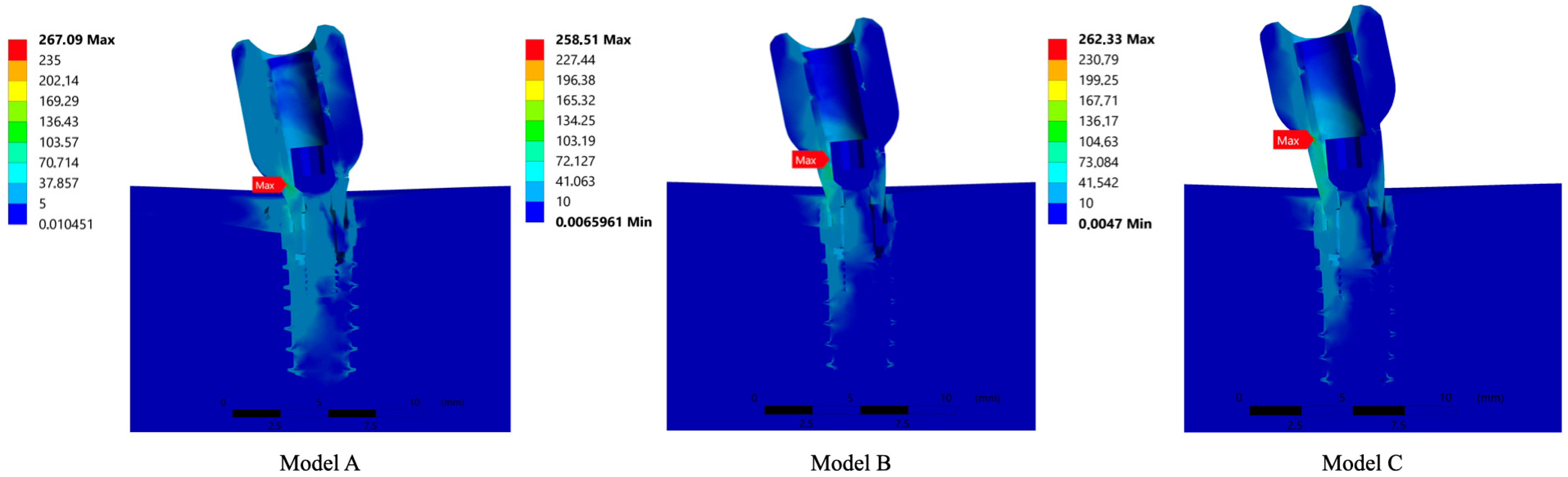
| System | 0.0065961–258.51 | 0–0.017129 | 0.0047–262.33 | 0–0.019033 | 0.010451–267.09 | 0–0.020255 |
| Crown | 0.42295–175.16 | 0.0049136–0.017129 | 0.43485–194.19 | 0.0056471–0.019033 | 0.43871–194.52 | 0.0067211–0.020255 |
| Abutment | 0.48626–258.51 | 0.0052729–0.015029 | 0.61873–262.33 | 0.0056696–0.01661 | 0.9399–267.09 | 0.0053955–0.017565 |
| Screw | 0.010451–35.017 | 0.0059213–0.0080568 | 0.006596–36.467 | 0.0059142–0.008087 | 0.0047–40.64 | 0.0059164–0.008274 |
| Implant | 0.068522–98.854 | 0.0053687–0.007732 | 0.10273–99.97 | 0.0053543–0.007735 | 0.10294–109.44 | 0.0053586–0.008014 |
| Cortical Bone | 0.0066727–32.344 | 0–0.007468 | 0.0077927–33.851 | 0–0.007677 | 0.011497–45.608 | 0–0.0081 |
| Trabecular Bone | 0.0066727–25.158 | 0–0.0072328 | 0.0077927–30.3165 | 0–0.007266 | 0.011457–35.475 | 0–0.0081 |
Disclaimer/Publisher’s Note: The statements, opinions and data contained in all publications are solely those of the individual author(s) and contributor(s) and not of MDPI and/or the editor(s). MDPI and/or the editor(s) disclaim responsibility for any injury to people or property resulting from any ideas, methods, instructions or products referred to in the content. |
© 2024 by the authors. Licensee MDPI, Basel, Switzerland. This article is an open access article distributed under the terms and conditions of the Creative Commons Attribution (CC BY) license (https://creativecommons.org/licenses/by/4.0/).
Share and Cite
Beltrán-Guijarro, M.; Pérez-Pevida, E.; Chávarri-Prado, D.; Estrada-Martínez, A.; Diéguez-Pereira, M.; Sánchez-Lasheras, F.; Brizuela-Velasco, A. Biomechanical Effects of Ti-Base Abutment Height on the Dental Implant System: A Finite Element Analysis. J. Funct. Biomater. 2024, 15, 101. https://doi.org/10.3390/jfb15040101
Beltrán-Guijarro M, Pérez-Pevida E, Chávarri-Prado D, Estrada-Martínez A, Diéguez-Pereira M, Sánchez-Lasheras F, Brizuela-Velasco A. Biomechanical Effects of Ti-Base Abutment Height on the Dental Implant System: A Finite Element Analysis. Journal of Functional Biomaterials. 2024; 15(4):101. https://doi.org/10.3390/jfb15040101
Chicago/Turabian StyleBeltrán-Guijarro, Miguel, Esteban Pérez-Pevida, David Chávarri-Prado, Alejandro Estrada-Martínez, Markel Diéguez-Pereira, Fernando Sánchez-Lasheras, and Aritza Brizuela-Velasco. 2024. "Biomechanical Effects of Ti-Base Abutment Height on the Dental Implant System: A Finite Element Analysis" Journal of Functional Biomaterials 15, no. 4: 101. https://doi.org/10.3390/jfb15040101
APA StyleBeltrán-Guijarro, M., Pérez-Pevida, E., Chávarri-Prado, D., Estrada-Martínez, A., Diéguez-Pereira, M., Sánchez-Lasheras, F., & Brizuela-Velasco, A. (2024). Biomechanical Effects of Ti-Base Abutment Height on the Dental Implant System: A Finite Element Analysis. Journal of Functional Biomaterials, 15(4), 101. https://doi.org/10.3390/jfb15040101