
A Novel Method for Fabricating the Undulating Structures at Dermal—Epidermal Junction by Composite Molding Process

 and
and 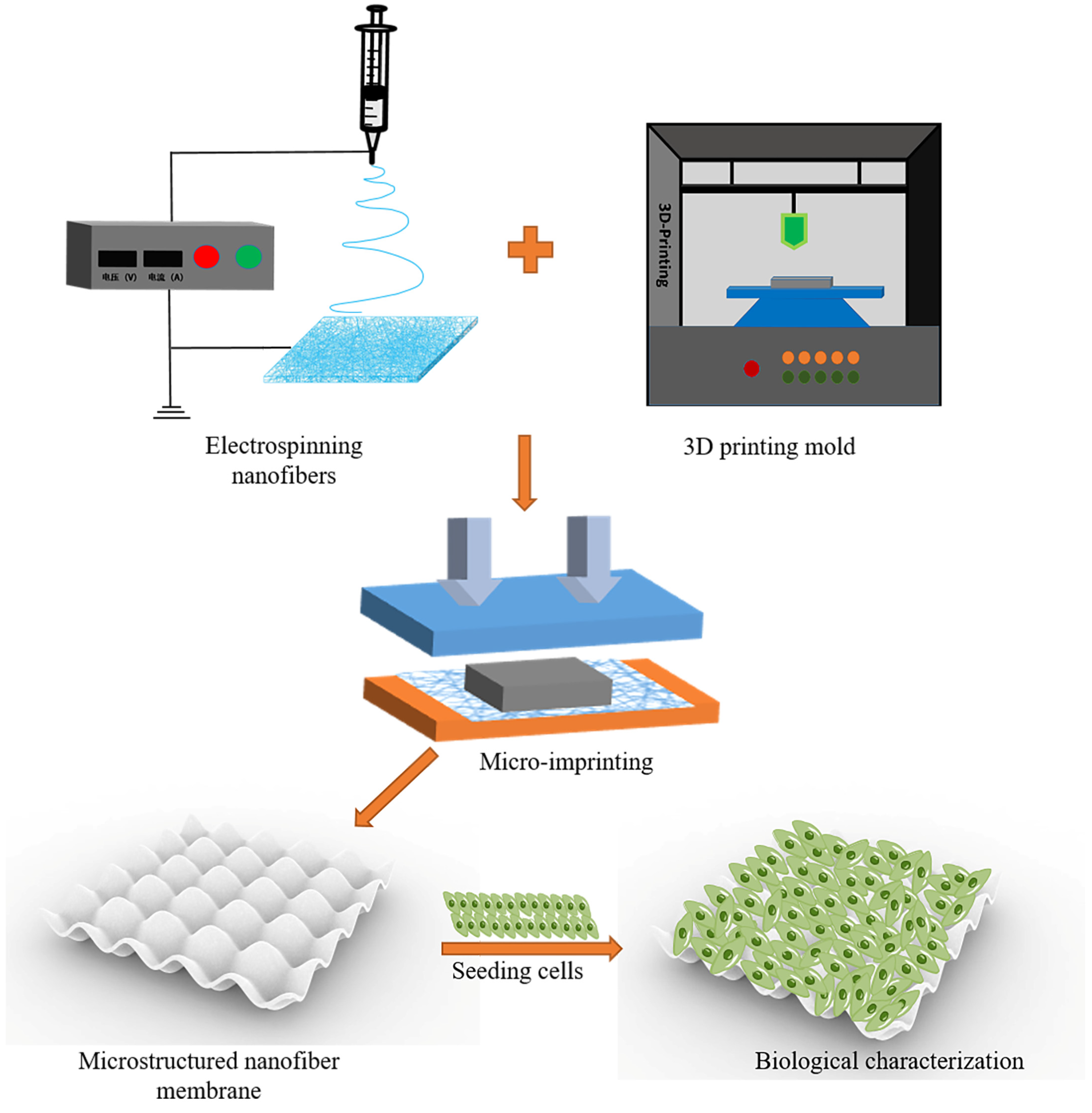
Abstract
:1. Introduction
2. Materials and Methods
2.1. Materials
2.2. Preparation of Electrospinning Solution
2.3. Electrospinning PLGA-PCL Nanofiber Membrane
2.4. Physical Characteristics of PLGA-PCL Nanofiber Membranes
2.4.1. Scanning Electron Microscope (SEM)
2.4.2. FTIR Test
2.4.3. Shrinkage Test
2.4.4. Hydrophilicity
2.4.5. Tensile Test
2.5. Cell Culture and Electrospinning Membranes Preparation
2.6. Biological Characterization of PLGA-PCL Membranes
2.6.1. HaCaTs Viability
2.6.2. HaCaTs Proliferation
2.6.3. HSFs Viability and Proliferation
2.7. Physical and Biological Characterization of Microstructured Membranes
2.7.1. Preparation of Nanofiber Membranes with Microstructures
2.7.2. Image Evaluation
2.7.3. Cell Viability and Proliferation
2.8. Statistical Analysis
3. Result
3.1. Physical Characteristics of PLGA-PCL Nanofiber Membranes
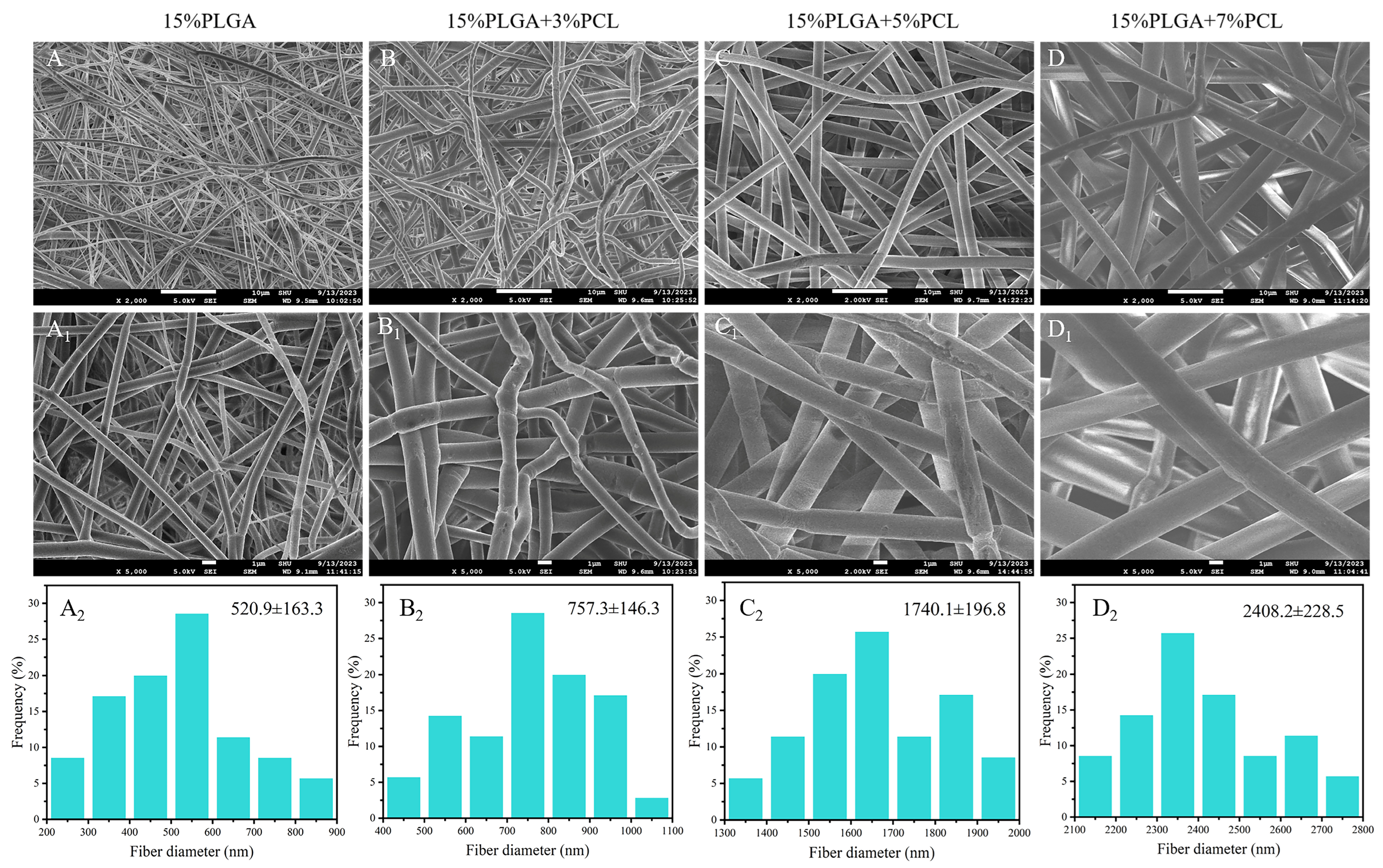
3.1.1. SEM
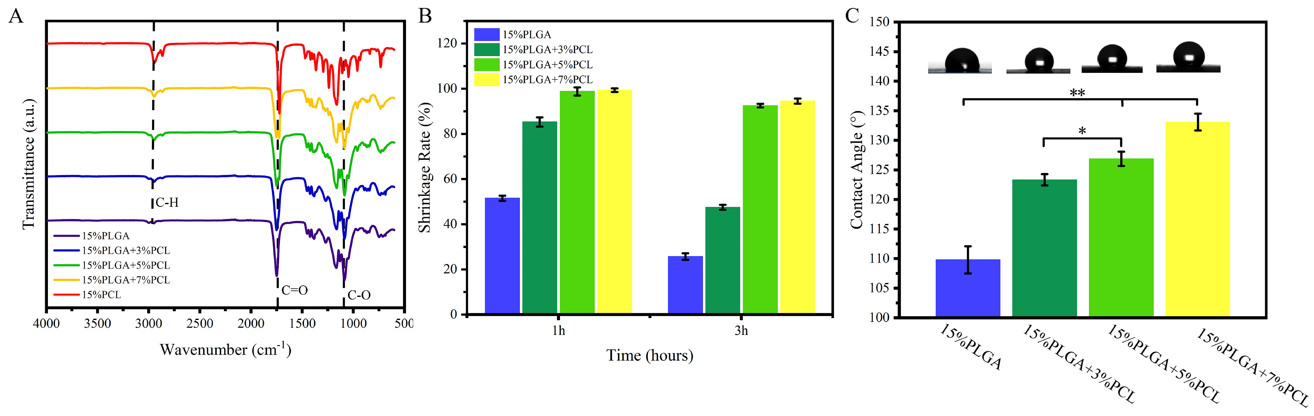
3.1.2. FTIR Analysis
3.1.3. Shrinkage Analysis
3.1.4. Hydrophilicity
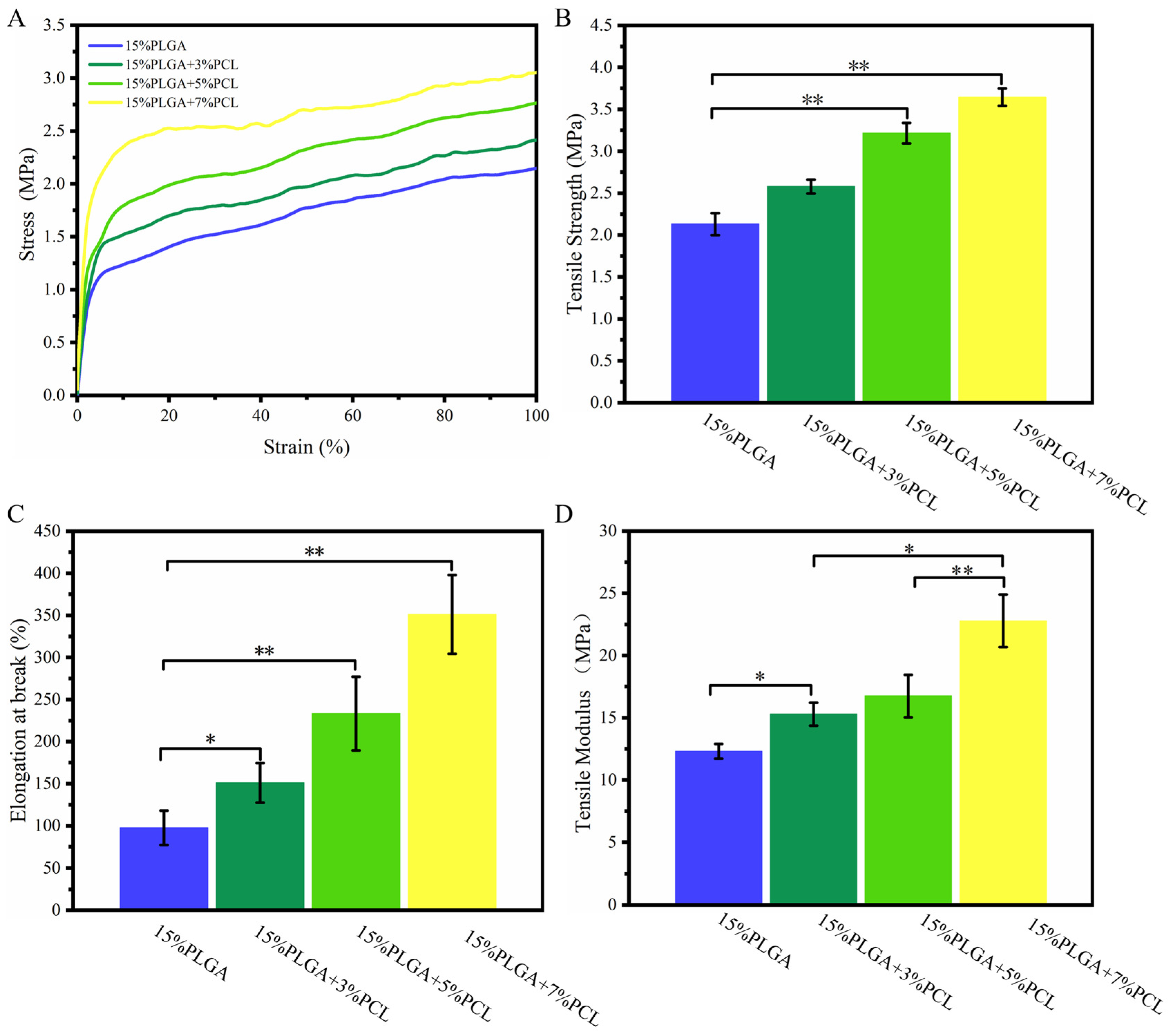
3.1.5. Tensile Analysis
3.2. Biological Characterization of PLGA-PCL Nanofiber Membranes
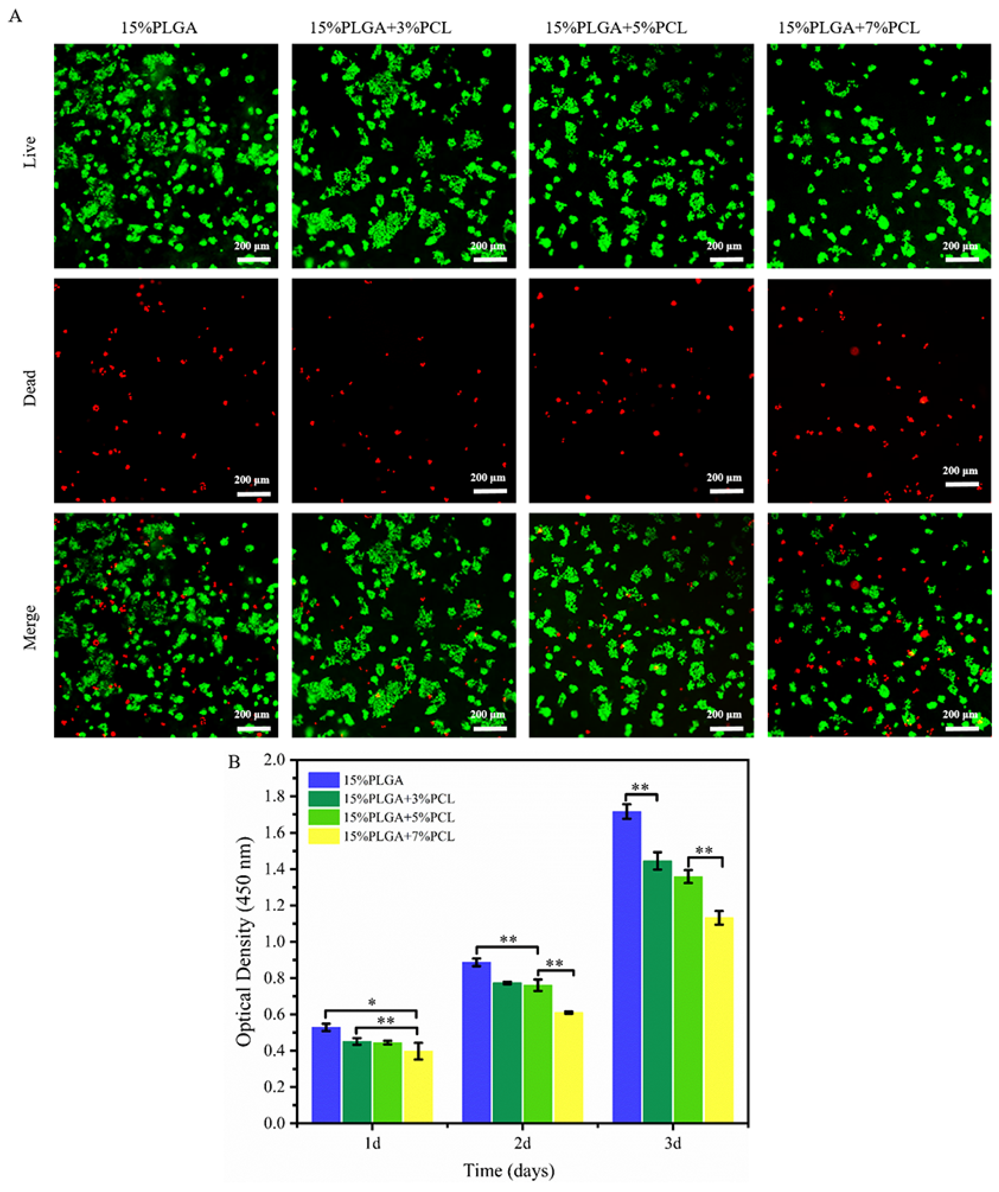
3.2.1. HaCaTs Viability and Proliferation
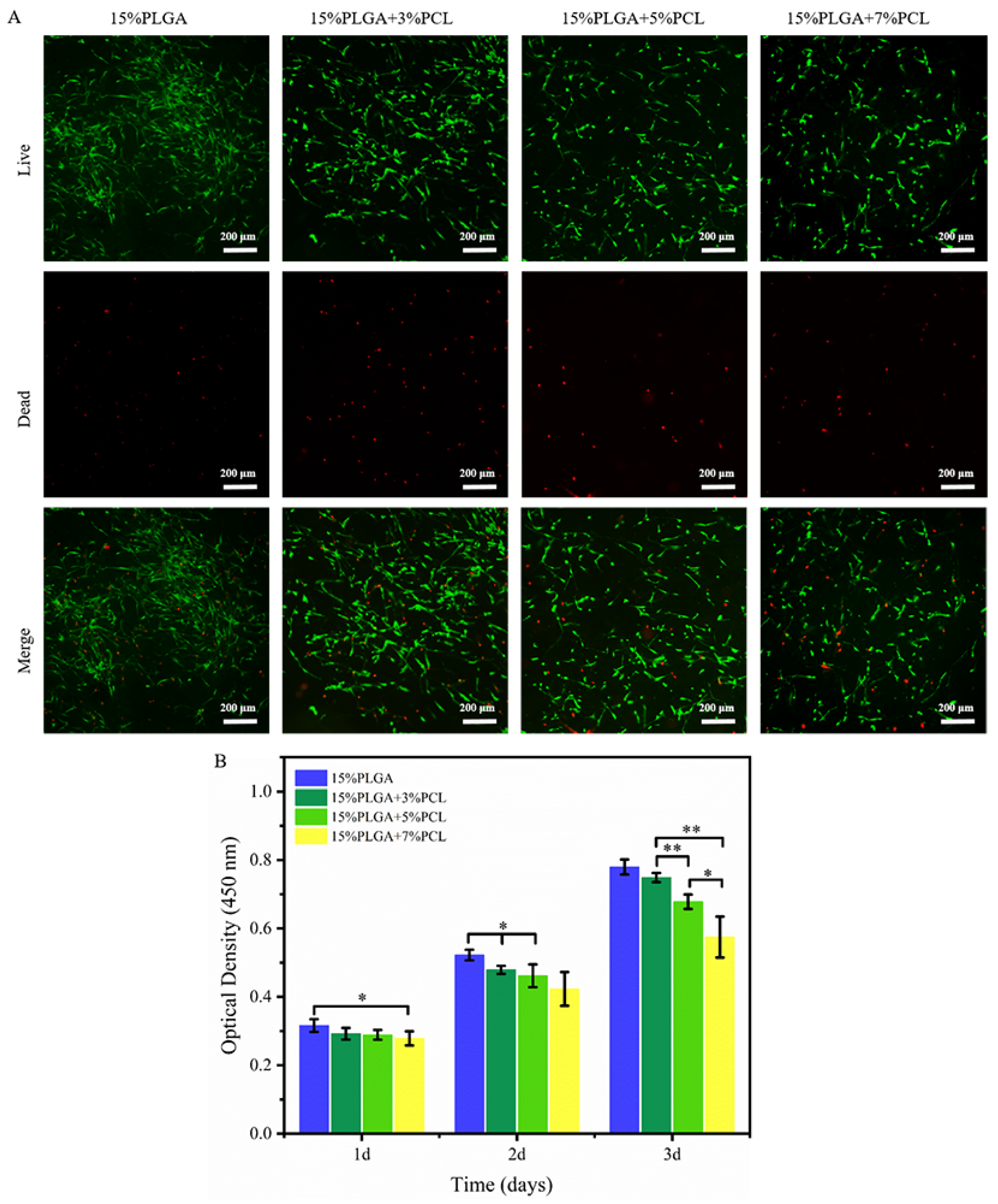
3.2.2. HSFs Viability and Proliferation
3.3. Physical and Biological Characterization of Microstructure Membrane
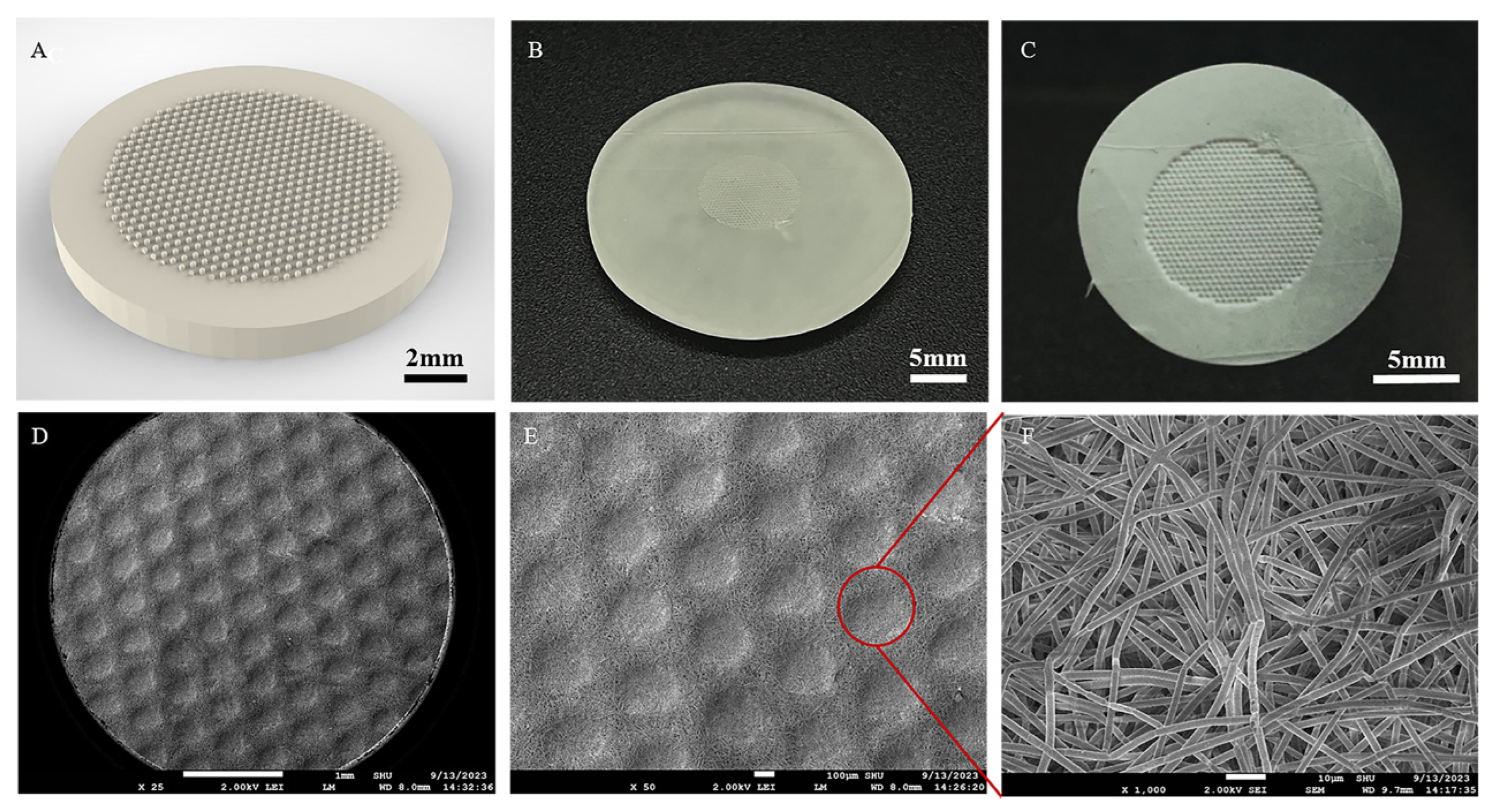
3.3.1. Image Evaluation
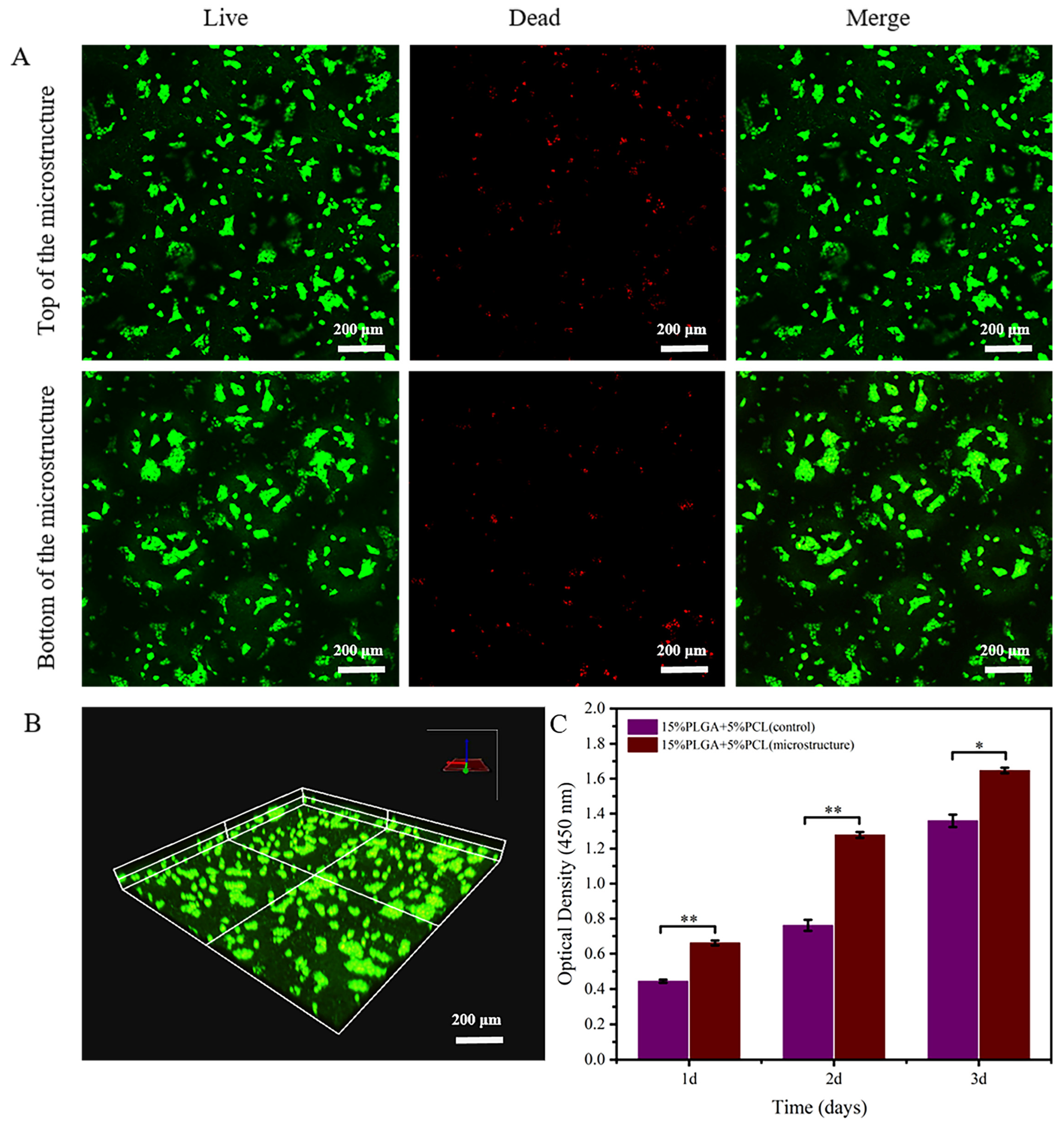
3.3.2. HaCaTs Viability and Proliferation
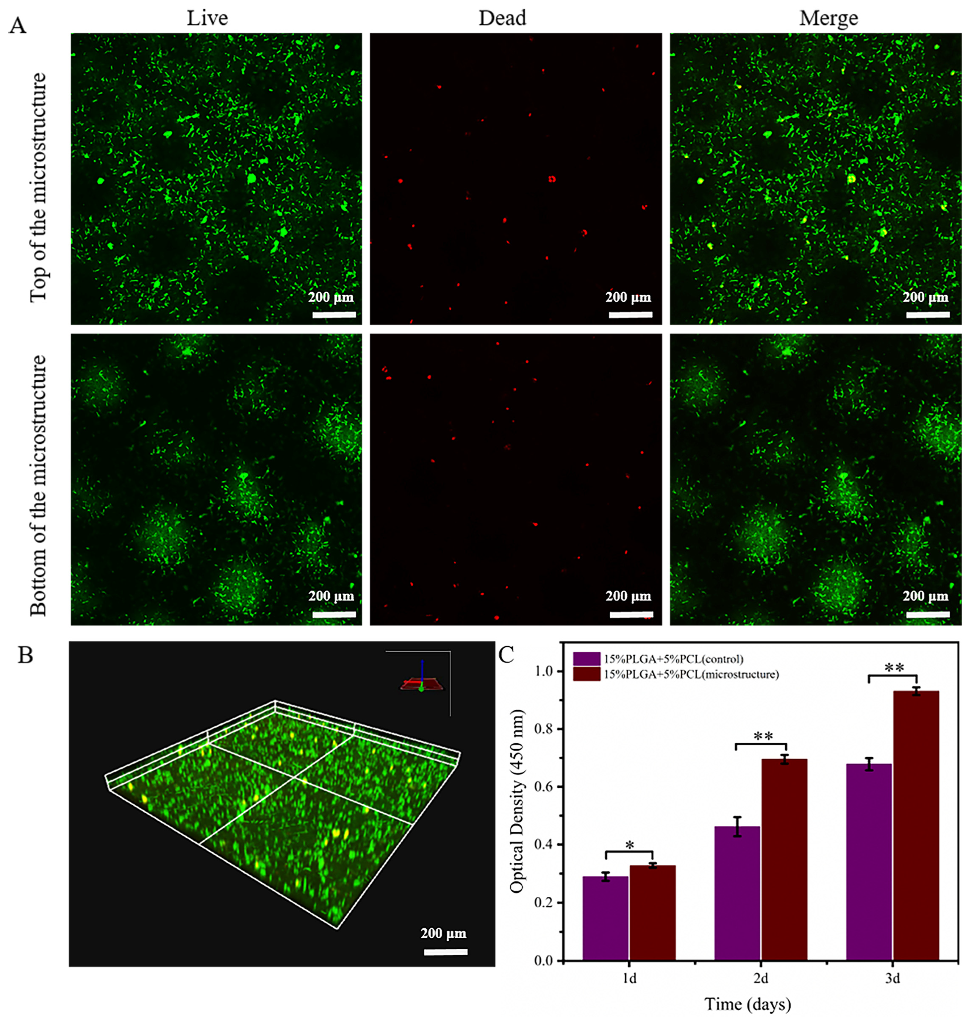
3.3.3. HSFs Viability and Proliferation
4. Discussion
5. Conclusions
Author Contributions
Funding
Data Availability Statement
Conflicts of Interest
References
- Jain, P.; Rauer, S.B.; Möller, M.; Singh, S. Mimicking the Natural Basement Membrane for Advanced Tissue Engineering. Biomacromolecules 2022, 23, 3081–3103. [Google Scholar] [CrossRef] [PubMed]
- Halfter, W.; Candiello, J.; Hu, H.Y.; Zhang, P.; Schreiber, E.; Balasubramani, M. Protein composition and biomechanical properties of in vivo-derived basement membranes. Cell Adhes. Migr. 2013, 7, 64–71. [Google Scholar] [CrossRef] [PubMed]
- Mak, K.M.; Mei, R. Basement Membrane Type IV Collagen and Laminin: An Overview of Their Biology and Value as Fibrosis Biomarkers of Liver Disease. Anat. Rec. 2017, 300, 1371–1390. [Google Scholar] [CrossRef] [PubMed]
- Youn, J.; Kim, D.S. Engineering porous membranes mimicking in vivo basement membrane for organ-on-chips applications. Biomicrofluidics 2022, 16, 051301. [Google Scholar] [CrossRef] [PubMed]
- Nagarajan, M.B.; Ainscough, A.J.; Reynolds, D.S.; Uzel, S.G.M.; Bjork, J.W.; A Baker, B.; McNulty, A.K.; Woulfe, S.L.; A Lewis, J. Biomimetic human skin model patterned with rete ridges. Biofabrication 2023, 16, 015006. [Google Scholar] [CrossRef] [PubMed]
- Shen, Z.; Sun, L.; Liu, Z.; Li, M.; Cao, Y.; Han, L.; Wang, J.; Wu, X.; Sang, S. Rete ridges: Morphogenesis, function, regulation, and reconstruction. Acta Biomater. 2023, 155, 19–34. [Google Scholar] [CrossRef]
- Shen, Z.; Cao, Y.; Li, M.; Yan, Y.; Cheng, R.; Zhao, Y.; Shao, Q.; Wang, J.; Sang, S. Construction of tissue-engineered skin with rete ridges using co-network hydrogels of gelatin methacrylated and poly(ethylene glycol) diacrylate. Mater. Sci. Eng. C 2021, 129, 112360. [Google Scholar] [CrossRef] [PubMed]
- Blackstone, B.N.; Malara, M.M.; Baumann, M.E.; McFarland, K.L.; Supp, D.M.; Powell, H.M. Fractional CO2 laser micropatterning of cell-seeded electrospun collagen scaffolds enables rete ridge formation in 3D engineered skin. Acta Biomater. 2020, 102, 287–297. [Google Scholar] [CrossRef] [PubMed]
- Mobasseri, S.A.; Zijl, S.; Salameti, V.; Walko, G.; Stannard, A.; Garcia-Manyes, S.; Watt, F.M. Patterning of human epidermal stem cells on undulating elastomer substrates reflects differences in cell stiffness. Acta Biomater. 2019, 87, 256–264. [Google Scholar] [CrossRef]
- Ramos-Rodriguez, D.H.; MacNeil, S.; Claeyssens, F.; Ortega Asencio, I. Fabrication of Topographically Controlled Electrospun Scaffolds to Mimic the Stem Cell Microenvironment in the Dermal-Epidermal Junction. ACS Biomater. Sci. Eng. 2021, 7, 2803–2813. [Google Scholar] [CrossRef]
- Norouzi, M.; Rafienia, M.; Hosseini, S. Characterization and biological evaluation of new PLGA/fibrin/lignin biocomposite electrospun scaffolds. Phys. Scr. 2023, 98, 095506. [Google Scholar] [CrossRef]
- Patra, A.; Satpathy, S.; Naik, P.K.; Kazi, M.; Hussain, M.D. Folate receptor-targeted PLGA-PEG nanoparticles for enhancing the activity of genistein in ovarian cancer. Artif. Cells Nanomed. Biotechnol. 2022, 50, 228–239. [Google Scholar] [CrossRef]
- Serris, I.; Serris, P.; Frey, K.M.; Cho, H. Development of 3D-Printed Layered PLGA Films for Drug Delivery and Evaluation of Drug Release Behaviors. AAPS PharmSciTech 2020, 21, 256. [Google Scholar] [CrossRef] [PubMed]
- Sutrisno, L.; Chen, H.; Yoshitomi, T.; Kawazoe, N.; Yang, Y.; Chen, G.P. PLGA–collagen–BPNS Bifunctional composite mesh for photothermal therapy of melanoma and skin tissue engineering. J. Mater. Chem. B 2022, 10, 204–213. [Google Scholar] [CrossRef] [PubMed]
- Wang, Z.; Liang, R.; Jiang, X.; Xie, J.; Cai, P.; Chen, H.; Zhan, X.; Lei, D.; Zhao, J.; Zheng, L. Electrospun PLGA/PCL/OCP nanofiber membranes promote osteogenic differentiation of mesenchymal stem cells (MSCs). Mater. Sci. Eng. C 2019, 104, 109796. [Google Scholar] [CrossRef] [PubMed]
- Qian, Y.; Zhou, X.; Zhang, F.; Diekwisch, T.G.H.; Luan, X.; Yang, J. Triple PLGA/PCL Scaffold Modification Including Silver Impregnation, Collagen Coating, and Electrospinning Significantly Improve Biocompatibility, Antimicrobial, and Osteogenic Properties for Orofacial Tissue Regeneration. ACS Appl. Mater. Interfaces 2019, 11, 37381–37396. [Google Scholar] [CrossRef] [PubMed]
- Zheng, C.; Attarilar, S.; Li, K.; Wang, C.; Liu, J.; Wang, L.; Yang, J.; Tang, Y. 3D-printed HA15-loaded β-Tricalcium Phosphate/Poly (Lactic-co-glycolic acid) Bone Tissue Scaffold Promotes Bone Regeneration in Rabbit Radial Defects. Int. J. Bioprinting 2021, 7, 100–111. [Google Scholar] [CrossRef] [PubMed]
- Yuan, C.; Jin, S.; Wei, J.; Huang, J.; Liu, C.; Lei, X.; Zuo, Y.; Li, J.; Li, Y. The shrinking behavior, mechanism and anti-shrinkage resolution of an electrospun PLGA membrane. J. Mater. Chem. B 2021, 9, 5861–5868. [Google Scholar] [CrossRef] [PubMed]
- Cui, W.; Zhu, X.; Yang, Y.; Li, X.; Jin, Y. Evaluation of electrospun fibrous scaffolds of poly(DL-lactide) and poly(ethylene glycol) for skin tissue engineering. Mater. Sci. Eng. C 2009, 29, 1869–1876. [Google Scholar] [CrossRef]
- Liu, P.; Sun, L.; Liu, P.; Yu, W.; Zhang, Q.; Zhang, W.; Ma, J.; Liu, P.; Shen, J. Surface modification of porous PLGA scaffolds with plasma for preventing dimensional shrinkage and promoting scaffold-cell/tissue interactions. J. Mater. Chem. B 2018, 6, 7605–7613. [Google Scholar] [CrossRef]
- Gao, C.; Lu, C.; Qiao, H.; Zhang, Y.; Liu, H.; Jian, Z.; Guo, Z.; Liu, Y. Strategies for vascularized skin models in vitro. Biomater. Sci. 2022, 10, 4724–4739. [Google Scholar] [CrossRef] [PubMed]
- Hwang, P.-A.; Chen, H.-Y.; Chang, J.-S.; Hsu, F.-Y. Electrospun nanofiber composite mat based on ulvan for wound dressing applications. Int. J. Biol. Macromol. 2023, 253, 126646. [Google Scholar] [CrossRef] [PubMed]
- Sun, X.; Zhang, Y.; Cui, J.; Zhang, C.; Xing, C.; Bian, H.; Lv, J.; Chen, D.; Xiao, L.; Su, J.; et al. Advanced multilayer composite dressing with co-delivery of gelsevirine and silk fibroin for burn wound healing. Compos. Part B Eng. 2023, 253, 110549. [Google Scholar] [CrossRef]
- Prasad, A.; Kandasubramanian, B. Fused deposition processing polycaprolactone of composites for biomedical applications. Polym. Plast. Technol. Mater. 2019, 58, 1365–1398. [Google Scholar] [CrossRef]
- Zheng, S.-Y.; Liu, Z.-W.; Kang, H.-L.; Liu, F.; Yan, G.-P.; Li, F. 3D-Printed scaffolds based on poly(Trimethylene carbonate), poly(ε-Caprolactone), and β-Tricalcium phosphate. Int. J. Bioprinting 2023, 9, 275–286. [Google Scholar] [CrossRef] [PubMed]
- Liu, Q.; Wang, H.; Chen, L.; Li, W.; Zong, Y.; Sun, Y.; Li, Z. Enzymatic degradation of fluorinated Poly(ε-caprolactone) (PCL) block copolymer films with improved hydrophobicity. Polym. Degrad. Stab. 2019, 165, 27–34. [Google Scholar] [CrossRef]
- Rahimkhoei, V.; Padervand, M.; Hedayat, M.; Seidi, F.; Dawi, E.A.; Akbari, A. Biomedical applications of electrospun polycaprolactone-based carbohydrate polymers: A review. Int. J. Biol. Macromol. 2023, 253, 126642. [Google Scholar] [CrossRef]
- Goncalves, A.M.M.; Leal, F.; Moreira, A.; Schellhorn, T.; Blahnová, V.H.; Zeiringer, S.; Vocetková, K.; Tetyczka, C.; Simaite, A.; Buzgo, M.; et al. Potential of Electrospun Fibrous Scaffolds for Intestinal, Skin, and Lung Epithelial Tissue Modeling. Adv. NanoBiomed Res. 2023, 3, 2200104. [Google Scholar] [CrossRef]
- Gao, C.; Lu, C.X.; Liu, H.Z.; Zhang, Y.; Qiao, H.; Jin, A.; Dai, Q.; Liu, Y. Biofabrication of biomimetic undulating microtopography at the dermal-epidermal junction and its effects on the growth and differentiation of epidermal cells. Biofabrication 2024, 16, 025018. [Google Scholar] [CrossRef]
- Ghobeira, R.; Philips, C.; Declercq, H.; Cools, P.; De Geyter, N.; Cornelissen, R.; Morent, R. Effects of different sterilization methods on the physico-chemical and bioresponsive properties of plasma-treated polycaprolactone films. Biomed. Mater. 2017, 2, 015017. [Google Scholar] [CrossRef]
- Liu, H.; Wang, S.; Qi, N. Controllable structure, properties, and degradation of the electrospun PLGA/PLA-blended nanofibrous scaffolds. J. Appl. Polym. Sci. 2012, 125, E468–E476. [Google Scholar] [CrossRef]
- Wang, Y.; Chen, Y.; Zhang, X.; Wang, H.; Gao, W. Effect of electrospinning parameters on diameter distribution of SCA nanofiber. J. Text. Res. 2010, 31, 6–10. [Google Scholar]
- Ng, K.W.; Hutmacher, D.W. Reduced contraction of skin equivalent engineered using cell sheets cultured in 3D matrices. Biomaterials 2006, 27, 4591–4598. [Google Scholar] [CrossRef] [PubMed]
- Liu, Y.; Jiang, H.-L.; Li, Y.; Zhu, K.-J. Control of dimensional stability and degradation rate in electrospun composite scaffold composed poly(D,L-lactice-co-glycolide) and poly(ε-caprolactone). Chin. J. Polym. Sci. 2008, 26, 63. [Google Scholar] [CrossRef]
- Cai, H.; Zhang, T.R.; Dai, R.X.; Song, S.; Han, R.; Li, Y.; Chen, J. Effect of poly(ε-caprolactone) microfibers in poly(lactide-co-glycolide) based bone fixation plate on preventing dimensional shrinkage and promoting cell interactions. Compos. Sci. Technol. 2021, 216, 109051. [Google Scholar] [CrossRef]
- Wang, Q.; Shao, W.; Gao, Y.; He, J.; Chen, L.; Cui, S. Biomimetic Mineralization and Biocompatibility of PLGA/TSF Electrospun Nanofibers. J. Mater. Sci. Eng. 2017, 35, 253–256,295. [Google Scholar]
- Wu, Q.; Ma, N.; Liu, T.; Koranteng, E. Properties of Compatible Soy Protein Isolate/Polycaprolactone Composite with Special Interface Structure. Polym. Compos. 2019, 40, E383–E391. [Google Scholar] [CrossRef]
- Zhang, F.; Qian, Y.; Chen, H.; Xu, Y.; Yang, J.; Zhou, X.; Gu, N. The preosteoblast response of electrospinning PLGA/PCL nanofibers: Effects of biomimetic architecture and collagen I. Int. J. Nanomed. 2016, 11, 4157–4171. [Google Scholar] [CrossRef]
- Ma, Y.; Ji, Y.; Zhong, T.; Wan, W.; Yang, Q.; Li, A.; Zhang, X.; Lin, M. Bioprinting-Based PDLSC-ECM Screening for in Vivo Repair of Alveolar Bone Defect Using Cell-Laden, Injectable and Photocrosslinkable Hydrogels. ACS Biomater. Sci. Eng. 2017, 3, 3534–3545. [Google Scholar] [CrossRef]
- Kenny, F.N.; Drymoussi, Z.; Delaine-Smith, R.; Kao, A.P.; Laly, A.C.; Knight, M.M.; Philpott, M.P.; Connelly, J.T. Tissue stiffening promotes keratinocyte proliferation through activation of epidermal growth factor signaling. J. Cell Sci. 2018, 131, 215780. [Google Scholar] [CrossRef]
- Chen, Y.; Liu, Y.; Zhang, P. Fabrication and Performance of Electrospinning Fiber Membrane for Bile Duct Stents. J. Donghua Univ. Nat. Sci. Ed. 2016, 42, 800–808. [Google Scholar]
- Jankovic, B.; Pelipenko, J.; Skarabot, M.; Musevic, I.; Kristl, J. The design trend in tissue-engineering scaffolds based on nanomechanical properties of individual electrospun nanofibers. Int. J. Pharm. 2013, 455, 338–347. [Google Scholar] [CrossRef] [PubMed]
- Pelipenko, J.; Kocbek, P.; Kristl, J. Nanofiber diameter as a critical parameter affecting skin cell response. Eur. J. Pharm. Sci. 2015, 66, 29–35. [Google Scholar] [CrossRef] [PubMed]
- Bye, F.J.; Bullock, A.J.; Singh, R.; Sefat, F.; Roman, S.; MacNeil, S. Development of a Basement Membrane Substitute Incorporated Into an Electrospun Scaffold for 3D Skin Tissue Engineering. J. Biomater. Tissue Eng. 2014, 4, 686–692. [Google Scholar] [CrossRef]
- Neal, R.A.; McClugage, S.G., III; Link, M.C.; Sefcik, L.S.; Ogle, R.C.; Botchwey, E.A. Laminin Nanofiber Meshes That Mimic Morphological Properties and Bioactivity of Basement Membranes. Tissue Eng. Part C Methods 2009, 15, 11–21. [Google Scholar] [CrossRef] [PubMed]
- Lee, E.J.; Lee, J.H.; Jin, L.; Jin, O.S.; Shin, Y.C.; Oh, S.J.; Lee, J.; Hyon, S.-H.; Han, D.-W. Hyaluronic Acid/Poly(lactic-co-glycolic acid) Core/Shell Fiber Meshes Loaded with Epigallocatechin-3-O-Gallate as Skin Tissue Engineering Scaffolds. J. Nanosci. Nanotechnol. 2014, 14, 8458–8463. [Google Scholar] [CrossRef] [PubMed]
- Xie, Z.; Buschle-Diller, G.; DeInnocentes, P.; Bird, R.C. Electrospun Poly(D,L)-Lactide Nonwoven Mats for Biomedical Application: Surface Area Shrinkage and Surface Entrapment. J. Appl. Polym. Sci. 2011, 122, 1219–1225. [Google Scholar] [CrossRef]
- Ru, C.; Wang, F.; Pang, M.; Sun, L.; Chen, R.; Sun, Y. Suspended, Shrinkage-Free, Electrospun PLGA Nanofibrous Scaffold for Skin Tissue Engineering. ACS Appl. Mater. Interfaces 2015, 7, 10872–10877. [Google Scholar] [CrossRef] [PubMed]
- Viswanathan, P.; Guvendiren, M.; Chua, W.; Telerman, S.B.; Liakath-Ali, K.; Burdick, J.A.; Watt, F.M. Mimicking the topography of the epidermal-dermal interface with elastomer substrates. Integr. Biol. 2016, 8, 21–29. [Google Scholar] [CrossRef]
- Lammers, G.; Roth, G.; Heck, M.; Zengerle, R.; Tjabringa, G.S.; Versteeg, E.M.; Hafmans, T.; Wismans, R.; Reinhardt, D.P.; Verwiel, E.T.P.; et al. Construction of a Microstructured Collagen Membrane Mimicking the Papillary Dermis Architecture and Guiding Keratinocyte Morphology and Gene Expression. Macromol. Biosci. 2012, 12, 675–691. [Google Scholar] [CrossRef]
- Helling, A.L.; Viswanathan, P.; Cheliotis, K.S.; Mobasseri, S.A.; Yang, Y.; El Haj, A.J.; Watt, F.M. Dynamic Culture Substrates That Mimic the Topography of the Epidermal-Dermal Junction. Tissue Eng. Part A 2019, 25, 214–223. [Google Scholar] [CrossRef] [PubMed]
- Norzain, N.A.; Lin, W.-C.; Razali, N.A.M. Triangular-prism Microstructure Engineered on the Fibrous Scaffold Using Electro-centrifugal Spinning Technique for Tissue Engineering. Fibers Polym. 2022, 23, 3398–3414. [Google Scholar] [CrossRef]


Disclaimer/Publisher’s Note: The statements, opinions and data contained in all publications are solely those of the individual author(s) and contributor(s) and not of MDPI and/or the editor(s). MDPI and/or the editor(s) disclaim responsibility for any injury to people or property resulting from any ideas, methods, instructions or products referred to in the content. |
© 2024 by the authors. Licensee MDPI, Basel, Switzerland. This article is an open access article distributed under the terms and conditions of the Creative Commons Attribution (CC BY) license (https://creativecommons.org/licenses/by/4.0/).
Share and Cite
Qiao, H.; Gao, C.; Lu, C.; Liu, H.; Zhang, Y.; Jin, A.; Dai, Q.; Yang, S.; Zhang, B.; Liu, Y. A Novel Method for Fabricating the Undulating Structures at Dermal—Epidermal Junction by Composite Molding Process. J. Funct. Biomater. 2024, 15, 102. https://doi.org/10.3390/jfb15040102
Qiao H, Gao C, Lu C, Liu H, Zhang Y, Jin A, Dai Q, Yang S, Zhang B, Liu Y. A Novel Method for Fabricating the Undulating Structures at Dermal—Epidermal Junction by Composite Molding Process. Journal of Functional Biomaterials. 2024; 15(4):102. https://doi.org/10.3390/jfb15040102
Chicago/Turabian StyleQiao, Hao, Chuang Gao, Chunxiang Lu, Huazhen Liu, Yi Zhang, Aoxiang Jin, Qiqi Dai, Shihmo Yang, Bing Zhang, and Yuanyuan Liu. 2024. "A Novel Method for Fabricating the Undulating Structures at Dermal—Epidermal Junction by Composite Molding Process" Journal of Functional Biomaterials 15, no. 4: 102. https://doi.org/10.3390/jfb15040102