Article

One Step Synthesis of Tetragonal-CuBi2O4/Amorphous-BiFeO3 Heterojunction with Improved Charge Separation and Enhanced Photocatalytic Properties

1
Guangdong Provincial Key Laboratory of Emergency Test for Dangerous Chemicals, Guangdong Institute of Analysis, Guangdong Academy of Sciences, Guangzhou 510070, China
2
Guangdong Engineering Technology Research Center of On-line Monitoring of Water Environmental Pollution, Guangdong Institute of Analysis, Guangdong Academy of Sciences, Guangzhou 510070, China
3
College of Petrochemical Technology, Lanzhou University of Technology, Lanzhou 730050, China
4
State Key Laboratory of Pulp and Paper Engineering, South China University of Technology, Guangzhou 510641, China
*
Author to whom correspondence should be addressed.
These authors contributed equally to this work.
Nanomaterials 2020, 10(8), 1514; https://doi.org/10.3390/nano10081514
Submission received: 8 July 2020 / Revised: 29 July 2020 / Accepted: 30 July 2020 / Published: 1 August 2020
(This article belongs to the Special Issue Catalysis by Metal-Oxide Nanostructures)

Abstract

:
Tetragonal CuBi2O4/amorphous BiFeO3 (T-CBO/A-BFO) composites are prepared via a one-step solvothermal method at mild conditions. The T-CBO/A-BFO composites show expanded visible light absorption, suppressed charge recombination, and consequently improved photocatalytic activity than T-CBO or A-BFO alone. The T-CBO/A-BFO with an optimal T-CBO to A-BFO ratio of 1:1 demonstrates the lowest photoluminescence signal and highest photocatalytic activity. It shows a removal rate of 78.3% for the photodegradation of methylene orange under visible light irradiation for 1 h. XPS test after the cycle test revealed the reduction of Bi3+ during the photocatalytic reaction. Moreover, the as prepared T-CBO/A-BFO show fundamentally higher photocatalytic activity than their calcinated counterparts. The one-step synthesis is completed within 30 min and does not require post annealing process, which may be easily applied for the fast and cost-effective preparation of photoactive metal oxide heterojunctions.

1. Introduction

Bismuth-based multinary metal oxides photocatalysts have attracted wide interest because of their high visible light photocatalytic activity [1]. The valence band of bismuth-based oxides is composed of hybrid orbitals of Bi 6s and O 2p, the presence of Bi 6s slightly above O 2p endows bismuth-based oxides with reduced bandgap for visible light absorption compared to other metal oxide semiconductors [2]. Among the various bismuth-based oxides, multinary metal oxides (BixMyOz, M represents other metal) have recently attracted increasing attention since they have shown fewer material limitations, higher controllability and enhanced photoactivity than their binary counterparts [3]. Specifically, CuBi2O4 has emerged as a promising photocatalytic material because of its suitable bandgap (1.5–1.8 eV) and high photovoltage [4,5,6]. Tetragonal CuBi2O4 possesses strong visible light absorption and exhibits great potential for photocatalytic degradation of organic pollutants [7,8,9]. Perovskite BiFeO3, with special multiferroic property for recycling, is another emerging bismuth-based multinary metal oxide showing great potential for photodegradation of organic pollutants due to its high visible light response [10,11,12]. However, both CuBi2O4 and BiFeO3 suffer from severe carrier recombination due to their intrinsic low polaron conductivity [13,14], which significantly limits their photocatalytic activities [15,16,17,18]. One way to suppress the carrier recombination is to form heterojunctions by combining two semiconductors. Lots of efforts have been paid to combine CuBi2O4 with TiO2 [19], NaTaO3 [20], SnO2 [21], CeO2 [22], g-C3N4 [5], Fe2O3 [7], Bi2WO6 [23], Bi2MoO6 [24], and incorporate BiFeO3 with Bi2WO6 [25], CuS [26], Ag3PO4 [27], BiOCl [11], CuO [28], ZnO [12], BiVO4 [29], C3N4 [30]. Such semiconductor combining has been proved to be an effective method to improve the charge separation and photoactivity of CuBi2O4 and BiFeO3. Nevertheless, in most cases the fabrication of the metal oxide-based heterojunction involves at least two steps: the preparation of each semiconductor photocatalyst, followed by the physical mixing and high temperature calcination [31]. The heterojunction is formed during high temperature calcination, which is largely limited by the thermal diffusion property of the semiconductor materials [32].
In this work, the T-CBO/A-BFO heterojunction was successfully formed within 30 min using a one-step solvothermal treatment at 120 °C without the need of post annealing. We demonstrated that the metal oxide photocatalysts do not necessarily need to be completely crystallized for high photocatalytic property. The formation of the T-CuBi2O4/A-BiFeO3 heterojunction resulted in significant improvement in visible light absorption up to 800 nm, enhanced charge separation, and consequently increased photocatalytic properties. We revealed that the oxidation and reduction of Bi3+ in the composite during the photocatalytic reaction highlights the importance of protection for the T-CBO/A-BFO. This work provides a facile and cost-effective method for the rapid fabrication of metal-oxides-based photoactive compounds.

2. Materials and Methods

2.1. Preparation

T-CBO/A-BFO and A-BFO were synthesized by a short-time solvothermal method we have developed previously for the preparation of T-CBO. Specifically the precursor solution of A-BFO was obtained by mixing 15 mL solution of 40 mmol/L Fe(NO3)3·9H2O (99.99%, Aladdin (China) Chemical Co. Ltd., Shanghai, China) in ethanol with 4.5 mL solution of 400 mmol/L Bi(NO3)3 (99.999%, Aladdin (China) Chemical Co. Ltd., Shanghai, China) in acetic acid. Total of 6.5 mol/L NaOH (98%, Alfa Aesar (China) Chemical Co. Ltd., Shanghai, China) solution was added to the precursor solution under magnetic stirring until pH 14 was reached; the mixture was then solvothermal treated at 120 °C in a 100 mL Teflon-lined steel autoclave for 30 min. For T-CBO/A-BFO composites, the precursor solutions were prepared by mixing Bi(NO3)3 in acetic acid (400 mmol/L), Cu(NO3)2·3H2O (99.99%, Aladdin (China) Chemical Co. Ltd., Shanghai, China) in ethanol (40 mmol/L), and Fe(NO3)3·9H2O in ethanol (40 mmol/L). Various T-CBO to A-BFO ratios (T-CBO/A-BFO (1:4), T-CBO/A-BFO (1:2), T-CBO/A-BFO (1:1), T-CBO/A-BFO (2:1), T-CBO/A-BFO (3:1), T-CBO/A-BFO (4:1)) could be obtained by adjusting the molar ratios of Cu(NO3)2·3H2O : Fe(NO3)3·9H2O : Bi(NO3)3 = (1:4:6, 1:2:4, 1:1:3, 2:1:5, 3:1:7, 4:1:9), the details for the preparation of solvothermal solutions with various ion ratios can be found in Table S1. To investigate the effect of post-annealing, the as prepared samples were calcinated in a Muffle furnace at 450 °C for 2 h.

2.2. Characterization

A Bruker D8 Advance X-ray diffractometer with Cu Kα radiation was used to analyze the crystal structure of the samples. Raman analysis was conducted using a BWS 465–785 H (BWTEK, Newark, DE, USA) spectrometer with a 785 nm laser source. Scanning electron microscopy (SEM, HITACHI, Tokyo, Japan) and a FEI Titan G2 60-300 transmission electron microscope (TEM, FEI Company, Hillsboro, OR, USA) were applied to characterize the morphologies of the photocatalysts. The chemical states of the elements were tested via an ESCALAB 250XI X-ray photoelectron spectroscopy (XPS, Thermo Fisher Scientific, Waltham, MA, USA). The surface area of the samples was estimated by the TriStar II 3 flex BET model (micrometrics, Norcross, GA, USA). The light absorption properties of the samples were collected on a UV-4100 spectrophotometer (HITACHI, Tokyo, Japan). Photoluminescence (PL) measurements were carried out using a FLS1000 Spectrophotometer (Edinburgh Instruments Ltd., Edinburgh, UK) with an excitation wavelength of 325 nm, fluorescence scanning range is 340 nm to 800 nm, scanning speed is 240 nm/min.

2.3. Photocatalytic Activity Measurement

Total of 20 mg photocatalyst was added to 50 mL methyl blue (MB) or methyl orange (MO) solution, and then magnetically stirred in the dark for 30 min to ensure adsorption/desorption equilibrium was achieved. Then, a trace amount of 50 μL H2O2 (30%) was added to the solution, and the photocatalytic degradation experiment was carried out at 26 °C under the illumination of a LED lamp (λ = 400~900 nm, 100 mW/cm2). Total of 2 mL aliquots were extracted from the solution and centrifuged at certain time intervals (5 to 20 min), and the absorption of the aliquots at 654 nm (maximum absorption wavelength of methylene blue) and 464 nm (maximum absorption wavelength of methylene orange) was measured on a UV-vis spectrophotometer. The standard curves were obtained by measuring standard solutions with different dye concentrations, from which the correlation between the absorption and dye concentration was determined. For the stability test, the MO solution was adjusted to the initial concentration and the separated photocatalyst was washed and reused after each cycle of the photocatalytic experiment. The degradation rate was calculated by Equation (1):
Degradation rate (%) = 1−Ct/C0
where C0 is the concentration of the initial dye solution, Ct is the remaining concentration of dye solution at a reaction time of t.

3. Results and Discussions

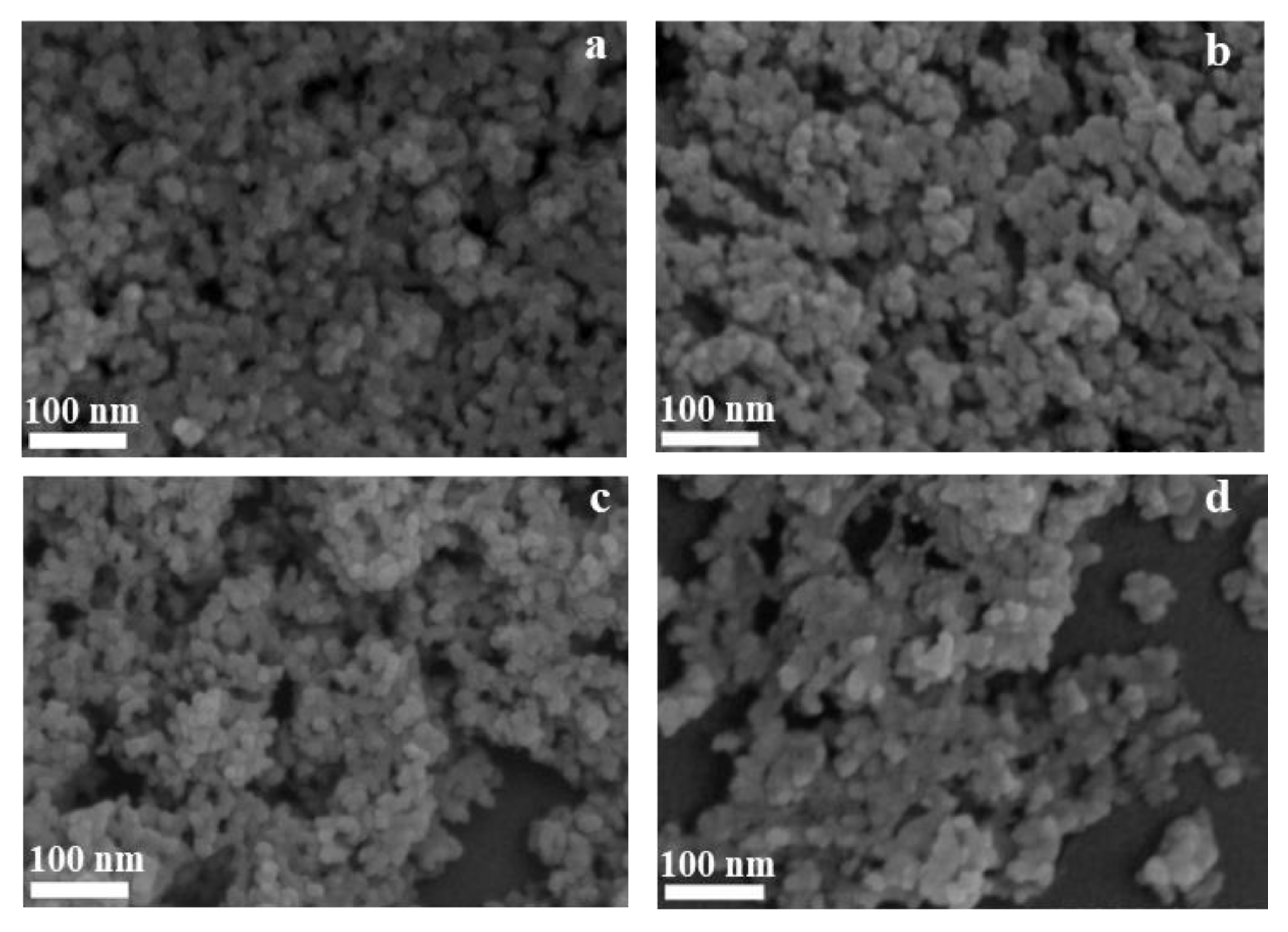
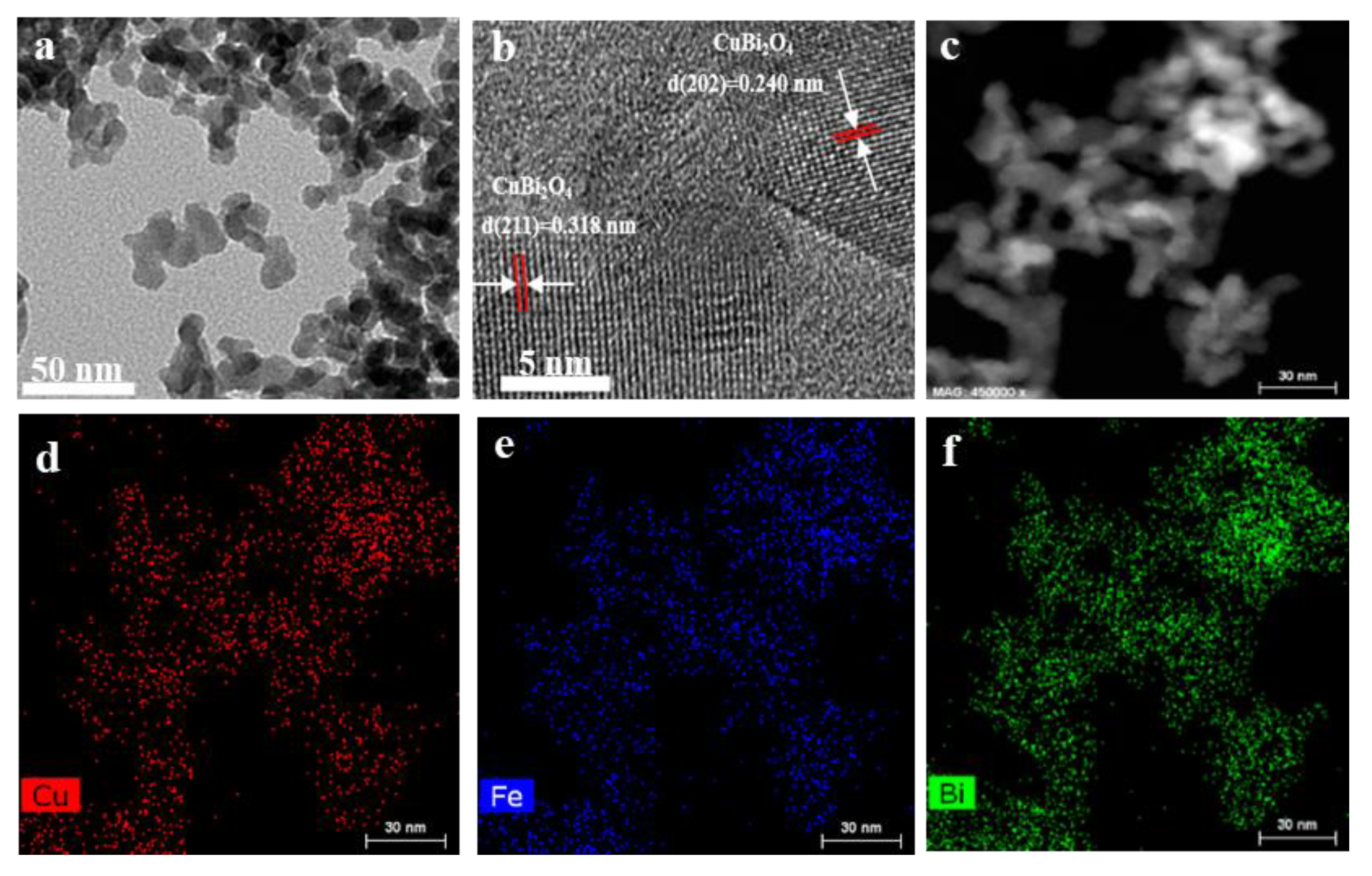
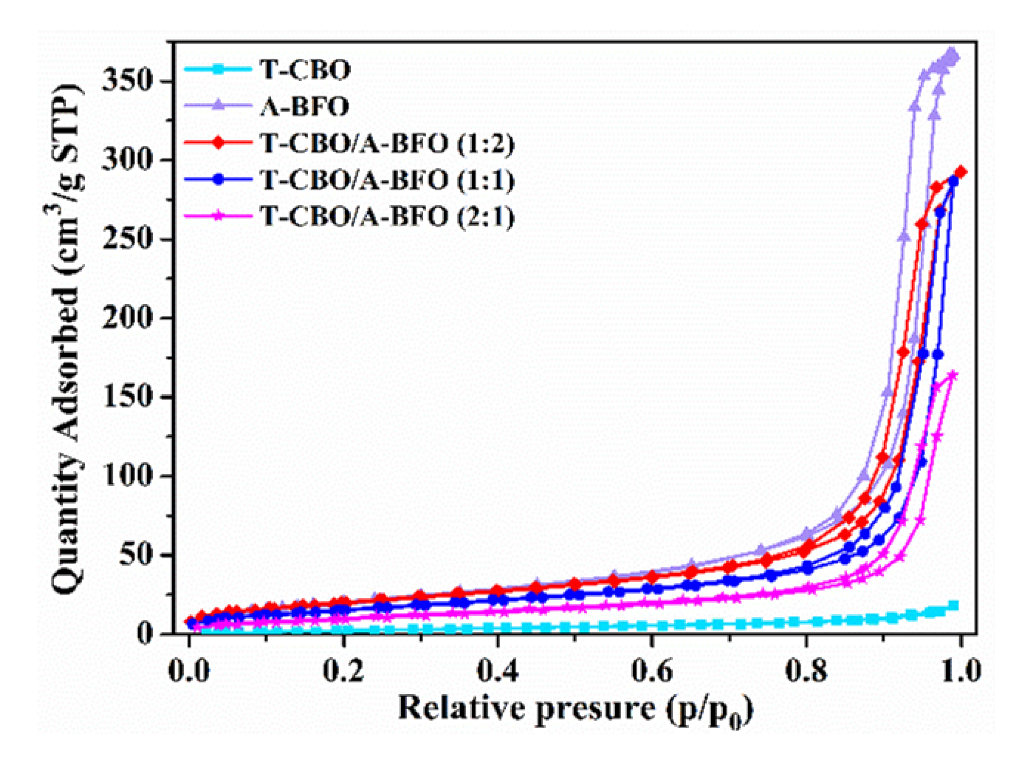
3.1. Crystal Structure, Morphology, and Composition

The XRD patterns of the as prepared CBO, BFO, and CBO/BFO composites were shown in Figure 1a. For CBO, diffraction peaks at 20.6°, 27.7°, 29.3°, 30.8°, 32.9°, 34.2°, 37.3°, 46.1°, 53.0°, 55.1°, 59.7°, and 65.8° were observed, which can be assigned to the (200), (211), (220), (002), (310), (112), (202), (411), (213), (332), (521), and (413) lattice planes of tetragonal CuBi2O4 (JCPDF 42-0334), respectively [9,20,22,33,34,35]. For the BFO, only one broad peak appeared at 32.07°, which might be attributed to the (110) peak of perovskite BiFeO3 [36,37]. This suggested that the as prepared BiFeO3 was mainly amorphous. The CBO/BFO with a CBO to BFO ratio of 1:2 showed a sharp peak at 27.7° in addition to a broad peak at 32.07°, which can be attributed to the (211) peak of tetragonal CuBi2O4 and the (110) peak of perovskite BiFeO3. As the CBO to BFO ratio increased to 1:1 and 2:1, all the peaks of tetragonal CBO appeared, while no characteristic peak of BFO was presented. This suggested that CBO/BFO composites showed the main structure of CBO, and the BFO remained amorphous, this is why they were denoted as T-CBO/A-BFO. To investigate the effect of annealing on the crystal structure, the as-prepared samples were calcined in a muffle furnace at 450 °C for 2 h and the XRD patterns of the samples before and after annealing were displayed in Figure S1a,1b, respectively. The T-CBO maintained the tetragonal structure after the calcination. For the A-BFO, the diffraction peaks at 22.42°, 31.75°, 32.07°, 39.48°, 45.75°, 51.31°, 51.74°, 56.97°, and 67.07° appeared after calcination, which can be assigned to the (012), (104), (110), (202), (024), (116), (122), (214), and (220) lattice planes of BiFeO3 (JCPDF 86-1518), respectively [36,37]. In addition, the diffraction peaks at 28.2°, 31.6°, 33.1°, 44.1°, 46.8°, 49.1°, and 53.5° were obviously observed, which can be attributed to the (400), (420), (332), (532), (541), (444), and (721) lattice planes of Bi25FeO40 (JCPDF 86-0368), respectively [36]. It has been reported that pure phase BiFeO3 was difficult to prepare via hydrothermal methods, and usually multiphase was obtained (e.g., Bi25FeO40, Bi2Fe4O9) [36]. However, after high temperature calcination, the T-CBO/A-BFO composites showed CBO and BFO diffraction peaks without the appearance of Bi25FeO40 or Bi2Fe4O9. This implied that rapid grown CBO could provide nucleation center for BFO. Raman spectroscopy was carried out to investigate the vibration modes of the samples, and the results are shown in Figure 1b. No obvious peak was found in the Raman spectra of A-BFO, which further confirmed that the as prepared A-BFO was amorphous as demonstrated in the XRD results. For T-CBO, three main Raman bands of tetragonal CuBi2O4 at 76, 121, and 256 cm−1 were observed. The band at 76 cm−1 corresponds to the B2g mode of the in-plane bending vibration of the Bi rhombohedra. The strong peak at 123 cm−1 can be assigned to the A1g mode of the translational vibration of the CuO4 plane along the Z-axis. The broad peak at 256 cm−1 is attribute to the rotation of two stacked CuO4 squares in opposite directions [38,39,40]. The T-CBO/A-BFO (1:1) showed main peaks of CuBi2O4 at the same position as T-CBO, indicating that the T-CBO/A-BFO (1:1) maintained the main structure of T-CBO.
SEM was performed to investigate the morphologies of T-CBO, A-BFO, and T-CBO/A-BFO composites, the images are shown in Figure 2. It can be observed that pure T-CBO photocatalysts (Figure S2) were formed by the self-assembling of nanorod arrays with a dumbbell-like morphology, more details of the T-CBO can be found in our previous report [9]. The A-BFO photocatalyst (Figure 2a) showed an irregular granular morphology with small particle size. Figure 2a–d showed the morphologies of T-CBO/A-BFO composites with different composite ratios. The T-CBO/A-BFO composites showed similar irregular granular morphology to A-BFO, and the particle size was obviously smaller than that of pure T-CBO.
The fine structure of T-CBO/A-BFO (1:1) composite was characterized by HRTEM. The nanoparticles of T-CBO/A-BFO (1:1) composites were observed in Figure 3a. The well-ordered lattice fringes were presented in Figure 3b, in which an interplanar spacing of 0.318 nm and 0.240 nm were observed, corresponding to the (211) and (202) plane of T-CBO, respectively [7,41,42]. No obvious A-BFO lattice fringes was found, which is consistent with the XRD and Raman results. This further confirmed the amorphous nature of BiFeO3 in the T-CBO/A-BFO (1:1) composite. The microstructure and elemental distribution of the T-CBO/A-BFO (1:1) composites photocatalyst were further investigated by HAADF-STEM and energy dispersive-ray spectroscopy (EDS). In the mapping area (Figure 3c), the Cu, Fe, and Bi were uniformly distributed in the T-CBO/A-BFO (1:1) composite, as shown in Figure 3d–f.
The chemical composition and elemental valence of T-CBO, A-BFO, and T-CBO/A-BFO (1:1) composite were analyzed by XPS, and the results are shown in Figure 4. The XPS survey spectra for the Cu, Bi, Fe, and O are displayed in Figure S3. All the XPS spectra were calibrated by the binding energy of C 1s at 284.8 eV. As shown in Figure 4a, T-CBO and T-CBO/A-BFO (1:1) showed two main peaks at around 933.8 eV and 953.6 eV and shake-up satellites at approximately 941.7 eV and 961.8 eV, which could be assigned to Cu 2p3/2 and Cu 2p1/2 binding energies of Cu2+, respectively [38,42,43,44]. In the A-BFO, two peaks at 710.3 eV and 724.8 eV were observed (Figure 4b), corresponding to the Fe 2p3/2 and Fe 2p1/2 peaks of Fe3+. In addition, two satellite peaks at 716.4 eV and 729.4 eV appeared in the A-BFO, which can be assigned to the Fe 2p3/2 and Fe 2p1/2 satellite of Fe2+, respectively. This suggests the co-existence of Fe3+ and Fe2+ in the A-BFO. Whereas in the T-CBO/A-BFO (1:1) composite, the peaks at 710.7 eV and 724.2 eV correspond to Fe 2p3/2 and Fe 2p1/2 of Fe3+, respectively, and the small satellite peak at 718.4 eV further confirmed the existence of Fe3+ [7,37]. No satellite peaks of Fe2+ was found in the T-CBO/A-BFO (1:1) composite, suggesting different valence bond mechanisms of A-BFO when it was co-synthesized with the T-CBO. In Figure 4c, the peak for O-mental bounds appeared at 529.4, 529.6, and 529.8 for the A-BFO, T-CBO, and T-CBO/A-BFO (1:1) respectively. The positive shift in the T-CBO/A-BFO (1:1) was due to the increase in binding energy of O-mental in the heterojunction. The peaks at around 531.5 eV can be assigned to the chemisorbed oxygen [45,46], and the peak at 532.7 eV in the A-BFO suggested the formation of metal-OH groups on the surface [47]. In Figure 4d, the T-CBO, A-BFO, and T-CBO/A-BFO (1:1) all showed peaks at around 158.7 eV and 164.0 eV, which can be assigned to Bi 4f 7/2 and Bi 4f 5/2 of Bi3+, respectively. The positive shift in the T-CBO/A-BFO (1:1) was attributed to the increasing bounding energy of Bi3+ with the surrounding O atoms due to the formation of the heterojunction. The A-BFO, in addition, had two peaks at 159.4 eV and 165.8 eV, which could be attributed to the Bi 4f 7/2 and Bi 4f 5/2 of Bi5+ [48]. This implied the co-existence of Bi3+ and Bi5+ in the A-BFO.
In general, photocatalysts with high specific surface area and large pore size are expected to provide more photocatalytic active sites, which is beneficial for improving the photocatalytic activity. To elucidate the effect of specific area, BET measurements were carried out. The N2 adsorption-desorption curves with T-CBO, A-BFO, and T-CBO/A-BFO with different composite ratios were displayed in Figure 5. It can be seen that all the samples had isotherms of type IV, indicating the presence of mesopores (2–50 nm). The isotherms exhibited H3 hysteresis loops at a high relative pressure range from 0.8 to 1.0, suggesting the presence of slit-like pores.
The BET surface area, pore volume, and average pore size of the samples are summarized in Table 1. The instrument for BET test (micrometrics, TriStar II 3 flex, THE UNITED STATES OF AMERICA) could extend specific surface area, pore volume, and average pore size measurements to as low as 0.001 m2/g, 4 × 10⁻⁶ cm3/g, and 0.01 nm, respectively. The uncertainties of the BET results were obtained by repeating the measurements three times, from which the standard deviation was calculated. The T-CBO and A-BFO showed a BET surface area of 11.60 m2/g and 80.39 m2/g, respectively. The surface area of the T-CBO/A-BFO composite was in between T-CBO and A-BFO, and increased from 38.95 m2/g to 74.18 m2/g as the T-CBO to A-BFO ratio decreased from 2:1 to 1:2. Specifically, the T-CBO/A-BFO (1:1) showed a surface area of 58.86, which is relatively higher compared to the reported values (7.2–28.1 m2/g) for BFO and its compounds [49,50].

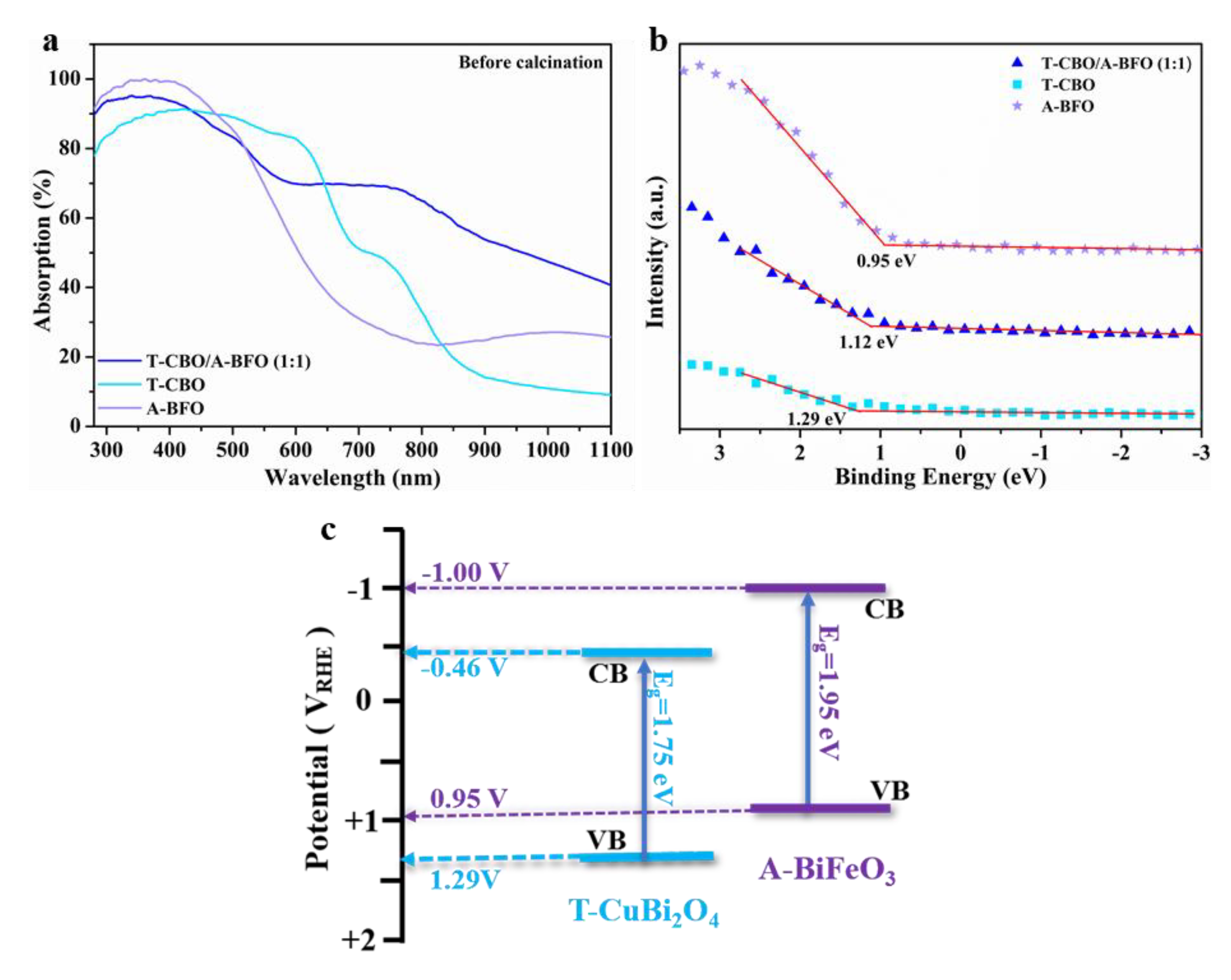
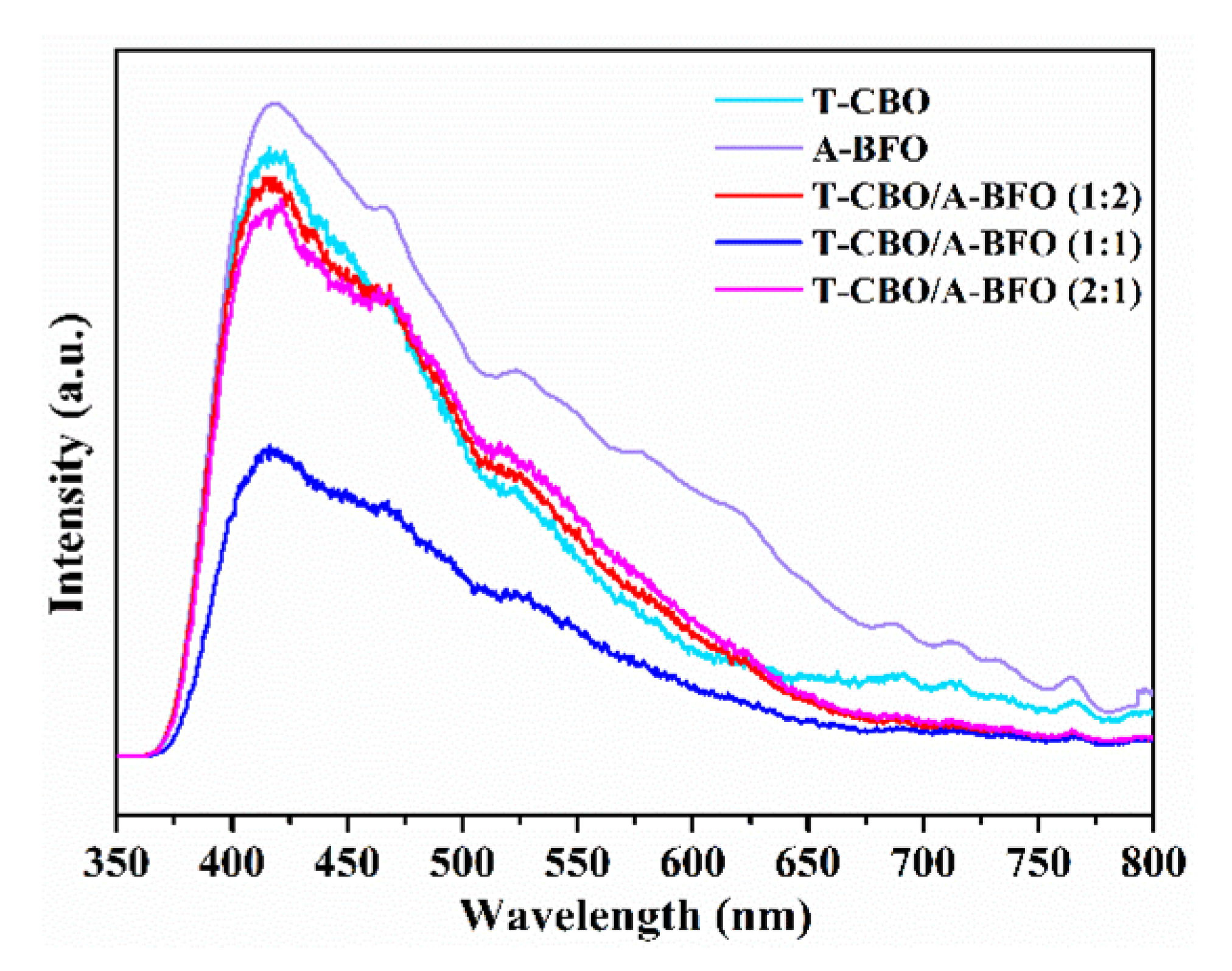
3.2. Optical and Electronic Properties

The optical absorption properties of the T-CBO, A-BFO, and T-CBO/A-BFO (1:1) were investigated by the UV-vis diffusive reflectance analyzer, and the spectra are shown in Figure 6a. UV-vis spectra for T-CBO/A-BFO composites with other T-CBO to A-BFO ratios were provided in Figure S4a, and the corresponding Tauc plots could be found in Figure S4b.
The A-BFO could effectively absorb light under 500 nm, while the T-CBO exhibited wide visible light absorption up to 800 nm. The T-CBO/A-BFO composites showed significant higher absorption and extended absorption region compared with the A-BFO. The bandgap of the T-CBO and A-BFO were estimated to be 1.75 eV, 1.95 eV from the Tauc plot (Figure S4b), and their valence band edge was determined to be 1.29 V and 0.95 V from the XPS VB spectra (Figure 6b). Based on the valence band positions and bandgaps of the T-CBO and A-BFO, we have tried to sketch an energy band diagram of the T-CBO/A-BFO composite, as shown in Figure 6c. The band edges of A-BFO are located slightly higher than those of T-CBO, such band alignment is beneficial for forming T-CBO/A-BFO heterojunction with improved charge separation efficiency. In the T-CBO/A-BFO heterojunction, the photo-generated electrons on the CB of A-BFO tend to move onto the CB of T-CBO, while the photo-generated holes on the VB of T-CBO can be effectively transferred to the VB of A-BFO.
To further investigate the carrier recombination and charge transfer properties, the T-CBO, A-BFO, and T-CBO/A-BFO (1:2), T-CBO/A-BFO (1:1), T-CBO/A-BFO (2:1) were evaluated by photoluminescence (PL) with an excitation wavelength of 325 nm and the results are shown in Figure 7. All the samples showed emission peak at about 420 nm. Both T-CBO and A-BFO exhibited strong emission peak, while a decrease in emission signal was observed in all the T-CBO/A-BFO composites, indicating inhibited carrier recombination in the composites. This confirmed that the formation of T-CBO/A-BFO heterojunction benefited the charge transfer between the T-CBO and A-BFO, as has been demonstrated in Figure 6c. The PL emission intensity decreased significantly as the T-CBO to A-BFO ratio increased from 1:2 to 1:1, further increasing the ratio to 2:1 resulted in a sharp increase in PL emission. This implied that recombination of photo-generated electron-hole pairs was effectively prohibited in the T-CBO/A-BFO composites and the optimal T-CBO to A-BFO ratio is 1:1.

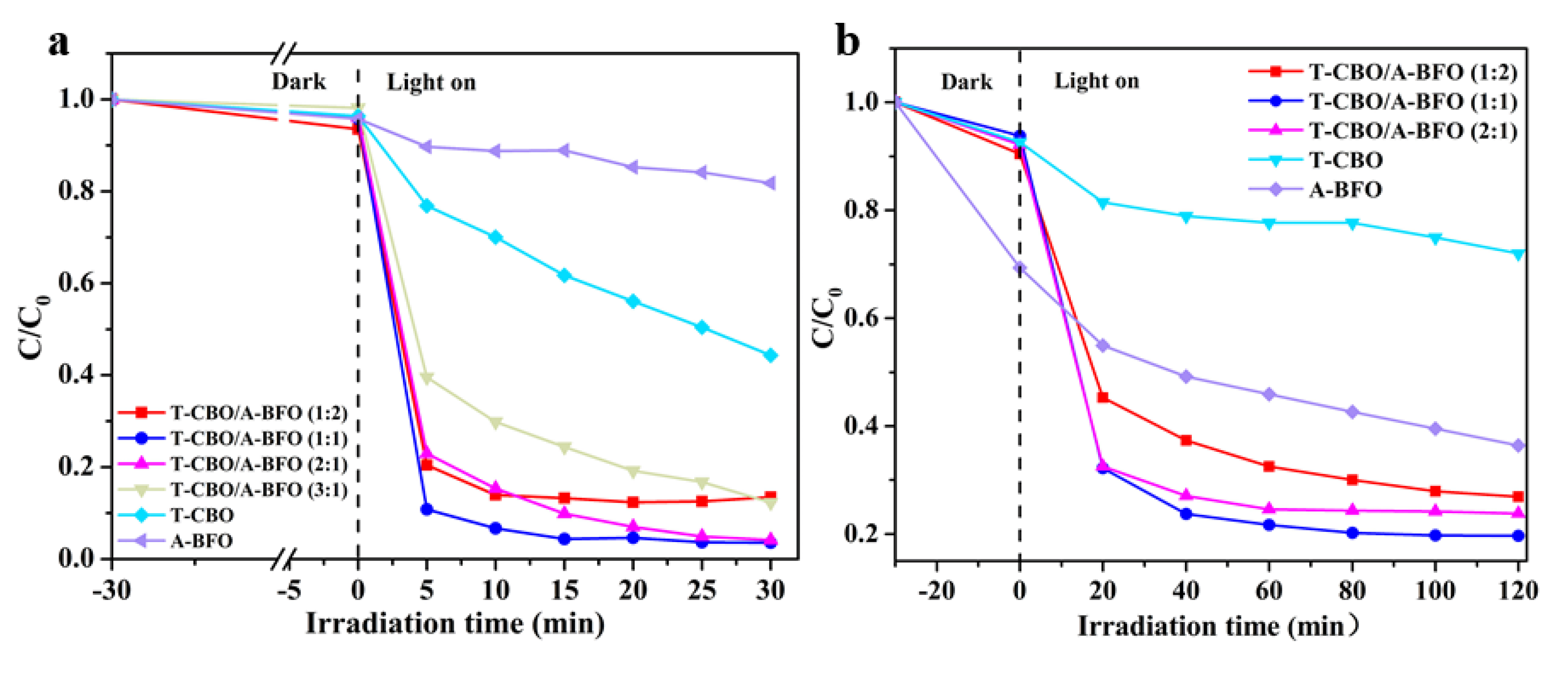
3.3. Photocatalytic Properties

The photocatalytic performance of the as-prepared samples was evaluated for the degradation of MB and MO under visible light. As shown in Figure 8, the MO concentration obviously decreased under dark, especially for the dye solution with A-BFO added as the photocatalyst. This is probably due to the strong physical absorption of dye on the surface of BiFeO3, which has been reported previously [51]. Among all our samples, A-BFO showed the highest BET surface area (80.39 m2/g, see Table 1). Previous study demonstrated that larger surface area could lead to higher absorption of dye in the dark [52]. After 30 min of visible light irradiation, the degradation rates of MB by the T-CBO and A-BFO photocatalysts were 56% and 19%, respectively. Obviously, the T-CBO/A-BFO composites showed increased photocatalytic property than the T-CBO and A-BFO alone. Based on the aforementioned results, we tried to elucidate the correlation between the crystal structure, specific surface area, light absorption property, carrier transfer of the samples with their photocatalytic properties. To investigate the effect of crystal structure, the as-prepared samples were calcined in a muffle furnace at 450 °C for 2 h and the photocatalytic property was tested. Tetragonal CBO and perovskite BFO were obtained after calcination (Figure S1b), which were commonly regarded as the photoactive phases. However, in our results the well crystalized tetragonal-CBO/perovskite-BFO composite after calcination showed substantially lower photoactivity than the as-prepared T-CBO/A-BFO (Figure S5), indicating that better crystallinity did not lead to higher photoactivity. With respect to the surface area, in our study the A-BFO processed the highest BET surface area (Table 1), but it exhibited the lowest photoactivity (Figure 8a). Therefore, specific surface area could not be the main determinant for the photocatalytic performance. Herein, the improved photoactivity of the CBO/A-BFO composite was mainly attributed to the extended visible light absorption (Figure 6a) and improved charge transfer of the T-CBO/A-BFO heterojunction (Figure 6). The photoactivity of the CBO/A-BFO composite increased as the T-CBO to A-BFO ratio increases from 1:2 to 1:1. Further increasing the ratio from 1:1 to 2:1 resulted in a decrease in photoactivity, which is probably due to the sharp increase in carrier recombination as demonstrated in Figure 7. The same trend in photoactivity was also found for the degradation of MO, as shown in Figure 8b. Among the T-CBO/A-BFO composites with various T-CBO to A-BFO ratios, the T-CBO/A-BFO (1:1) composite exhibited the best photocatalytic performance and it could photodegrade 97% MB within 30 min and 80% MO within 80 min. An interesting observation about the T-CBO/A-BFO 1:2 and 2:1 was that they showed PL signal almost as high as the T-CBO or A-BFO alone, whereas their photocatalytic activity were close to that of T-CBO/A-BFO 1:1. This suggested that other factors (e.g., light absorption, surface area) played an important role in the photocatalytic activity of the T-CBO/A-BFO 1:2 and 2:1, even though they might not be the main determinants. Specifically, T-CBO/A-BFO 2:1 possessed considerably higher visible light absorption in the range of 520–800 nm compared to T-CBO/A-BFO 1:1, as shown in Figure S4a. T-CBO/A-BFO 1:2 exhibited much higher specific surface area (74.18 m2/g) than the T-CBO/A-BFO 1:1 (58.86 m2/g).
Moreover, we also prepared T-CBO and A-BFO composite by simply physically mixing T-CBO and A-BFO at a ratio of 1:1, and the photocatalytic performance was tested (Figure S6). The experimental results showed that the degradation rate of MO by the physically mixed T-CBO/A-BFO was slightly higher than that of T-CBO or A-BFO alone, but still much lower than that of the one-step synthesized T-CBO/A-BFO (1:1) composite. This indicated that a solid heterojunction T-CBO/A-BFO (1:1) was formed during the solvothermal reaction, leading to improved charge carrier separation and enhanced photocatalytic performance.

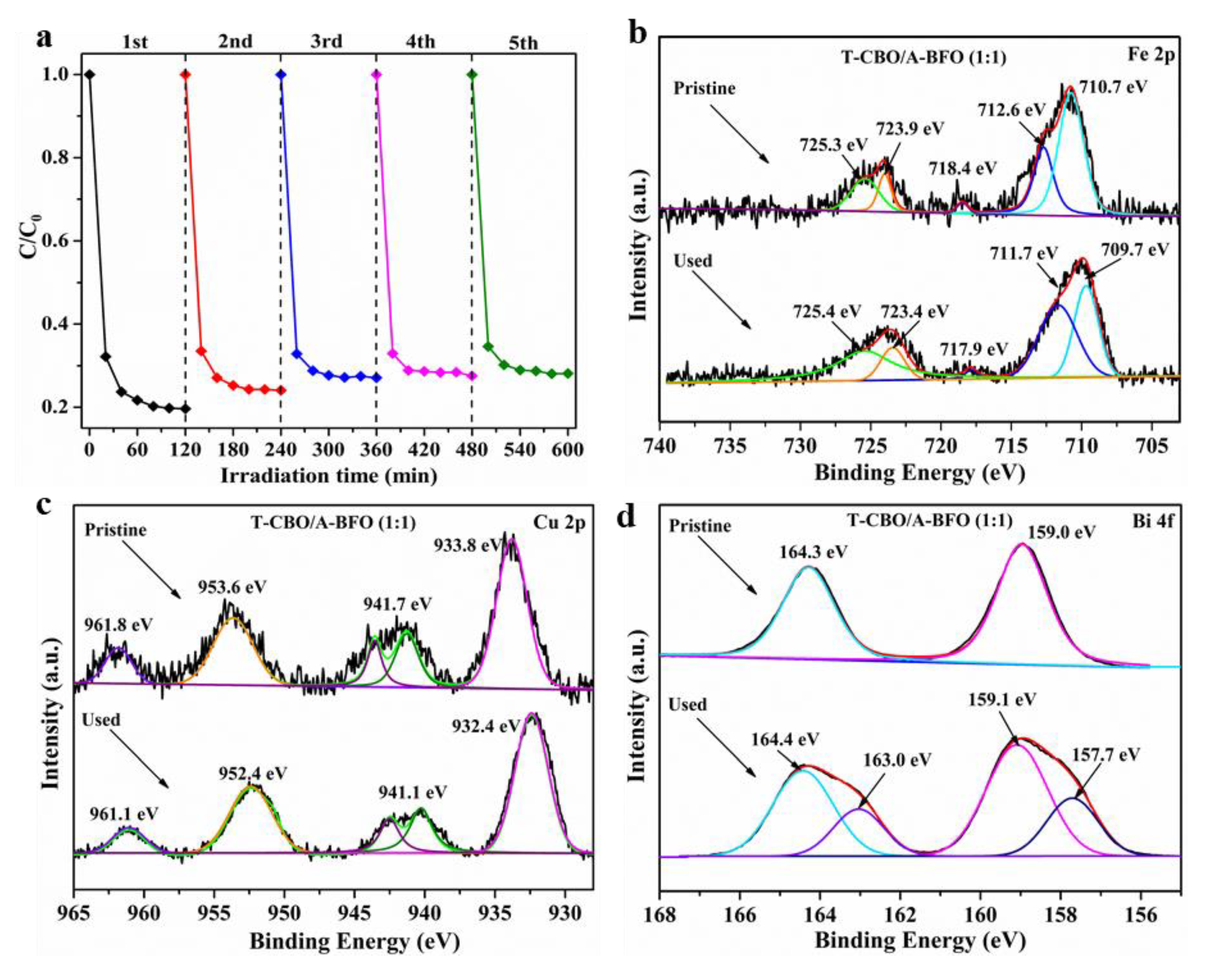
3.4. Stability of the T-CBO/A-BFO (1:1) Composite

Eventually, the stability of the T-CBO/A-BFO (1:1) composite was evaluated by repeating photodegradation experiments under visible light irradiation for 5 cycles. As illustrated in Figure 9a, after five cycles of experiments, the decomposition rate of MO by the T-CBO/A-BFO (1:1) slightly decreased by 8.4%, demonstrating the relatively high stability of the as-prepared T-CBO/A-BFO (1:1) composite photocatalyst. We note that the decrease may be partially due to the loss of the sample powder during the separation and cleaning processes. XPS of Fe, Cu, and Bi was performed before and after the stability test, as shown in Figure 9b–d. No significant change was found for Fe 2p (Figure 9b) and Cu 2p (Figure 9c) before and after the stability test. However, in the Bi 4f spectra, two new peaks at lower binding energy of 157.7 and 163.0 appeared after the cycle experiments, suggesting the reduction of Bi3+ into lower valence states such as Bi2.75 [53], Bi2+ [54] during the photocatalytic test. Previously we have demonstrated that the T-CBO was stable after 5 cycles photodegradation test [9], therefore the reduction of Bi3+ was presumably taking place in the A-BFO of the T-CBO/A-BFO composite. This may be part of the reason for the decreased photocatalytic property in the cycle experiment. Our results highlight the importance of preventing Bi3+ from reduction to further improve the stability of the T-CBO/A-BFO composite.

4. Conclusions

In this study, a T-CBO/A-BFO composite was prepared using a facile one-step method. A 30-min solvothermal treatment at 120 °C resulted in T-CBO/A-BFO composites with extended visible light absorption region, lower charge recombination and consequently higher photocatalytic performance compared to T-CBO or A-BFO alone. The photoluminance intensity of the CBO/A-BFO composite decreased as the T-CBO to A-BFO ratio increases from 1:2 to 1:1. Further increasing the ratio from 1:1 to 2:1 resulted in a sharp increase in photoluminance intensity. The CBO/A-BFO (1:1) composite showed the lowest photoluminance intensity, indicating suppressed carrier recombination and improved the charge transfer in the heterojunction. The CBO/A-BFO (1:1) composite had a high BET surface area of 58.86 m2/g, and exhibited wide visible light absorption up to 800 nm. It could degrade 95.6% MB within 15 min, and 78.3% MO within 1 h under visible light illumination. The reduction of Bi3+ was observed after the photocatalytic stability test. The CBO/A-BFO (1:1) composite prepared by the one-step method showed significantly higher photocatalytic activity than the physically mixed T-CBO and A-BFO with a ratio of 1:1, which demonstrates the advantage of the one-step synthesized T-CBO/A-BFO heterojunction. Moreover, the as prepared CBO/A-BFO (1:1) composite exhibited substantially higher photocatalytic performance than its post annealed counterpart. The short-time synthesis method was carried out at mild reaction conditions and high temperature calcination was not required. This work provides an easy and cost-effective route for the fast preparation of multinary metal oxide-based heterojunctions for photocatalytic applications.

Supplementary Materials

The following are available online at https://www.mdpi.com/2079-4991/10/8/1514/s1. Figure S1: XRD patterns of the T-CBO, A-BFO, and T-CBO/A-BFO composites (a) before annealing; (b) after annealing at 450 °C for 2 h. Figure S2: SEM images of the T-CBO. Figure S3: XPS survey spectra of Cu 2p, Fe 2p, O 1s, Bi 4f of the T-CBO, A-BFO and T-CBO/A-BFO (1:1). Figure S4: (a) UV-vis diffuse reflectance spectra; (b) corresponding Tauc plots of the T-CBO, A-BFO, and T-CBO/A-BFO composites. Figure S5: Photodegradation of MB by post annealed CBO, BFO, and CBO/BFO composites. Figure S6: Photodegradation of MO by T-CBO/A-BFO (1:1) and physical mixed T-CBO and A-BFO at a ratio of 1:1.

Author Contributions

Conceptualization, F.W. and F.C.; methodology, F.C., T.Z., and Q.L.; investigation, F.C., T.Z., and Q.L.; resources, F.W., P.G., Y.L., and Y.W.; data curation, F.C., T.Z., and Q.L.; writing—original draft preparation, F.W. and F.C.; writing—review and editing, F.W., P.G., Y.L., and Y.W.; supervision, F.W. and P.G.; project administration, F.W., P.G., and Y.W.; funding acquisition, F.W., P.G., and Y.W. All authors have read and agreed to the published version of the manuscript.

Funding

This work was funded by the National Natural Science Foundation of China, grant number 61904167 and 21707128; GDAS' Project of Science and Technology Development, grant number 2020GDASYL-20200102006; Natural Science Foundation of Guangdong Province, grant number 2019A151501208; Funding of Guangdong Provincial Key Laboratory of Emergency Test for Dangerous Chemicals, grant number KF2018001. Q. L. acknowledges the China Postdoctoral Science Foundation (No. 2020M672638) for financial support.

Acknowledgments

The authors thank the financial support by National Natural Science Foundation of China, grant number 61904167 and 21707128; GDAS' Project of Science and Technology Development, grant number 2020GDASYL-20200102006; Natural Science Foundation of Guangdong Province, grant number 2019A151501208; Funding of Guangdong Provincial Key Laboratory of Emergency Test for Dangerous Chemicals, grant number KF2018001. Q. L. acknowledges the China Postdoctoral Science Foundation (No. 2020M672638) for financial support.

Conflicts of Interest

The authors declare no conflict of interest.

References

  1. Meng, X.; Zhang, Z. Bismuth-based photocatalytic semiconductors: Introduction, challenges and possible approaches. J. Mol. Catal. A Chem. 2016, 423, 533–549. [Google Scholar] [CrossRef]
  2. He, R.; Cao, S.; Zhou, P.; Yu, J. Recent advances in visible light Bi-based photocatalysts. Chin. J. Catal. 2014, 35, 989–1007. [Google Scholar] [CrossRef]
  3. Abdi, F.F.; Berglund, S.P. Recent developments in complex metal oxide photoelectrodes. J. Phys. D Appl. Phys. 2017, 50, 193002. [Google Scholar] [CrossRef]
  4. Kang, D.; Hill, J.C.; Park, Y.; Choi, K.-S. Photoelectrochemical properties and photostabilities of high surface area CuBi2O4 and Ag-doped CuBi2O4 photocathodes. Chem. Mater. 2016, 28, 4331–4340. [Google Scholar] [CrossRef]
  5. Guo, F.; Shi, W.; Wang, H.; Huang, H.; Liu, Y.; Kang, Z. Fabrication of a CuBi2O4/g-C3N4 p–n heterojunction with enhanced visible light photocatalytic efficiency toward tetracycline degradation. Inorg. Chem. Front. 2017, 4, 1714–1720. [Google Scholar] [CrossRef]
  6. Wang, F.; Chemseddine, A.; Abdi, F.F.; Krol, R.v.d.; Berglund, S.P. Spray pyrolysis of CuBi2O4 photocathodes: Improved solution chemistry for highly homogeneous thin films. J. Mater. Chem. A. 2017, 5, 12838–12847. [Google Scholar] [CrossRef]
  7. Li, M.Y.; Tang, Y.-B.; Shi, W.-L.; Chen, F.-Y.; Shi, Y.; Gu, H.C. Design of visible-light-response core–shell Fe2O3/CuBi2O4 heterojunctions with enhanced photocatalytic activity towards the degradation of tetracycline: Z-scheme photocatalytic mechanism insight. Inorg. Chem. Front. 2018, 5, 3148–3154. [Google Scholar] [CrossRef]
  8. Chen, X.; Dai, Y.; Guo, J. Hydrothermal synthesis of well-distributed spherical CuBi2O4 with enhanced photocatalytic activity under visible light irradiation. Mater. Lett. 2015, 161, 251–254. [Google Scholar] [CrossRef]
  9. Wang, Y.; Cai, F.; Guo, P.; Lei, Y.; Xi, Q.; Wang, F. Short-Time Hydrothermal Synthesis of CuBi2O4 Nanocolumn Arrays for Efficient Visible-Light Photocatalysis. Nanomaterials 2019, 9, 1257. [Google Scholar] [CrossRef] [Green Version]
  10. Lam, S.M.; Sin, J.C.; Mohamed, A.R. A newly emerging visible light-responsive BiFeO3 perovskite for photocatalytic applications: A mini review. Mater. Res. Bull. 2017, 90, 15–30. [Google Scholar] [CrossRef]
  11. Shang, J.; Chen, H.; Chen, T.; Wang, X.; Feng, G.; Zhu, M.; Yang, Y.; Jia, X. Photocatalytic degradation of rhodamine B and phenol over BiFeO3/BiOCl nanocomposite. Appl. Phys. A 2019, 125, 1331–1337. [Google Scholar] [CrossRef]
  12. Sahni, M.; Kumar, D.; Chauhan, S.; Singh, M.; Kumar, N. Study of structural, optical and photocatalytic activity of Sm and Ni doped BiFeO3 (BFO) and BFO@ZnO nanostructure. Mater. Today Proc. 2020, 28, 56–60. [Google Scholar] [CrossRef]
  13. Sivula, K.; Roel, V.D.K. Semiconducting materials for photoelectrochemical energy conversion. Nat. Rev. Mater. 2016, 1, 15010. [Google Scholar] [CrossRef]
  14. Henrich, V.E.; Cox, P.A. The Surface Science of Metal Oxides; Cambridge University Press: Cambridge, UK, 1994. [Google Scholar] [CrossRef] [Green Version]
  15. Wang, F.; Septina, W.; Chemseddine, A.; Abdi, F.F.; Friedrich, D.; Bogdanoff, P.; Krol, R.v.d.; Tilley, S.D.; Berglund, S.P. Gradient self-doped CuBi2O4 with highly improved charge separation efficiency. J. Am. Chem. Soc. 2017, 139, 15094–15103. [Google Scholar] [CrossRef] [PubMed] [Green Version]
  16. Sheu, Y.M.; Trugman, S.A.; Xiong, J.; Park, Y.S.; Lee, S.; Yi, H.T.; Cheong, S.W.; Jia, Q.X.; Taylor, A.J.; Prasankumar, R.P. Ultrafast carrier dynamics and radiative recombination in multiferroic BiFeO3 single crystals and thin films. In Proceedings of EPJ Web of Conferences; EDP Sciences: Les Ulis, France, 2013; Volume 41, p. 03018. [Google Scholar] [CrossRef] [Green Version]
  17. Sheikh, M.S.; Ghosh, D.; Bhowmik, T.K.; Dutta, A.; Bhattacharyya, S.; Sinha, T.P. When multiferroics become photoelectrochemical catalysts: A case study with BiFeO3/La2NiMnO6. Mater. Chem. Phys. 2020, 244, 122685. [Google Scholar] [CrossRef]
  18. Berglund, S.P.; Abdi, F.F.; Bogdanoff, P.; Chemseddine, A.; Friedrich, D.; Krol, R.v.d. Comprehensive Evaluation of CuBi2O4 as a photocathode material for photoelectrochemical water splitting. Chem. Mater. 2016, 28, 4231–4242. [Google Scholar] [CrossRef]
  19. Wei, L.; Shifu, C.; Sujuan, Z.; Wei, Z.; Huaye, Z.; Xiaoling, Y. Preparation and characterization of p–n heterojunction photocatalyst p-CuBi2O4/n-TiO2 with high photocatalytic activity under visible and UV light irradiation. J. Nanopart. Res. 2009, 12, 1355–1366. [Google Scholar] [CrossRef]
  20. Deng, Y.; Chen, Y.; Chen, B.; Ma, J. Preparation, characterization and photocatalytic activity of CuBi2O4/NaTaO3 coupled photocatalysts. J. Alloys Compd. 2013, 559, 116–122. [Google Scholar] [CrossRef]
  21. Abdelkader, E.; Nadjia, L.; Ahmed, B. Preparation and characterization of novel CuBi2O4/SnO2 p–n heterojunction with enhanced photocatalytic performance under UVA light irradiation. J. King Saud Univ. Sci. 2015, 27, 76–91. [Google Scholar] [CrossRef] [Green Version]
  22. Elaziouti, A.; Laouedj, N.; Bekka, A.; Vannier, R.-N. Preparation and characterization of p–n heterojunction CuBi2O4/CeO2 and its photocatalytic activities under UVA light irradiation. J. King Saud Univ. Sci. 2015, 27, 120–135. [Google Scholar] [CrossRef] [Green Version]
  23. Yuan, X.; Shen, D.; Zhang, Q.; Zou, H.; Liu, Z.; Peng, F. Z-scheme Bi2WO6/CuBi2O4 heterojunction mediated by interfacial electric field for efficient visible-light photocatalytic degradation of tetracycline. Chem. Eng. J. 2019, 369, 292–301. [Google Scholar] [CrossRef]
  24. Shi, H.; Fan, J.; Zhao, Y.; Huc, X.; Zhang, X.; Tang, Z. Visible light driven CuBi2O4/Bi2MoO6 p-n heterojunction with enhanced photocatalytic inactivation of E. coli and mechanism insight. J. Hazard. Mater. 2020, 381, 121006. [Google Scholar] [CrossRef] [PubMed]
  25. Samran, B.; Saranyoo, C. Highly enhanced photoactivity of BiFeO3/Bi2WO6 composite films under visible light irradiation. Physica B 2019, 575, 411683. [Google Scholar] [CrossRef]
  26. Mishra], B.G. Photocatalytic degradation of alachlor using type-II CuS/BiFeO3 heterojunctions as novel photocatalyst under visible light irradiation. Chem. Eng. J. 2018, 344, 391–401. [Google Scholar] [CrossRef]
  27. Di, L.; Yang, H.; Xian, T.; Chen, X. Facile Synthesis and Enhanced Visible-Light Photocatalytic Activity of Novel p-Ag3PO4/n-BiFeO3 Heterojunction Composites for Dye Degradation. Nanoscale Res. Lett. 2018, 13, 257. [Google Scholar] [CrossRef]
  28. Niu, F.; Chen, D.; Qin, L.; Zhang, N.; Wang, J.; Chen, Z.; Huang, Y. Facile Synthesis of Highly Efficient p-n Heterojunction CuO/BiFeO3 Composite Photocatalysts with Enhanced Visible-Light Photocatalytic Activity. Chemcatchem 2015. [Google Scholar] [CrossRef]
  29. Soltani, T.; Tayyebi, A.; Lee, B.-K. BiFeO3/BiVO4 p−n heterojunction for efficient and stable photocatalytic and photoelectrochemical water splitting under visible-light irradiation. Catal. Today 2018, 340, 188–196. [Google Scholar] [CrossRef]
  30. Hu, X.; Wang, W.; Xie, G.; Wang, H.; Tan, X.; Jin, Q.; Zhou, D.; Zhao, Y. Ternary assembly of g-C3N4/graphene oxide sheets /BiFeO3 heterojunction with enhanced photoreduction of Cr(VI) under visible-light irradiation. Chemosphere 2019, 216, 733–741. [Google Scholar] [CrossRef]
  31. Theerthagiri, J.; Chandrasekaran, S.; Salla, S.; Elakkiya, V.; Senthil, R.A.; Nithyadharseni, P.; Maiyalagan, T.; Micheal, K.; Ayeshamariam, A.; Arasu, M.V.; et al. Recent developments of metal oxide based heterostructures for photocatalytic applications towards environmental remediation. J. Solid State Chem. 2018, 267, 35–52. [Google Scholar] [CrossRef]
  32. De Mendonça, V.R.; Dalmaschio, C.J.; Leite, E.R.; Niederberger, M.; Ribeiro, C. Heterostructure formation from hydrothermal annealing of preformed nanocrystals. J. Mater. Chem. A 2015, 3, 2216–2225. [Google Scholar] [CrossRef]
  33. Wang, F.; Yang, H.; Zhang, Y. Enhanced photocatalytic performance of CuBi2O4 particles decorated with Ag nanowires. Mater. Sci. Semicond. Process. 2018, 73, 58–66. [Google Scholar] [CrossRef]
  34. Zhang, Y.C.; Yang, H.; Wang, W.P.; Zhang, H.M.; Li, R.S.; Wang, X.X.; Yu, R.C. A promising supercapacitor electrode material of CuBi2O4 hierarchical microspheres synthesized via a coprecipitation route. J. Alloys Compd. 2016, 684, 707–713. [Google Scholar] [CrossRef]
  35. Elaziouti, A.; Laouedj, N.; Bekka, A. Synergetic effects of Sr-doped CuBi2O4 catalyst with enhanced photoactivity under UVA- light irradiation. Environ. Sci. Pollut. Res. Int. 2016, 23, 15862–15876. [Google Scholar] [CrossRef] [PubMed]
  36. Duan, Q.; Kong, F.; Han, X.; Jiang, Y.; Liu, T.; Chang, Y.; Zhou, L.; Qin, G.; Zhang, X. Synthesis and characterization of morphology-controllable BiFeO3 particles with efficient photocatalytic activity. Mater. Res. Bull. 2019, 112, 104–108. [Google Scholar] [CrossRef]
  37. Li, Y.; Wang, X.-T.; Zhang, X.-Q.; Li, X.; Wang, J.; Wang, C.-W. New hydrothermal synthesis strategy of nano-sized BiFeO3 for high-efficient photocatalytic applications. Phys. E Low Dimens. Syst. Nanostruct. 2020, 118, 113865. [Google Scholar] [CrossRef]
  38. Yuvaraj, S.; Karthikeyan, K.; Kalpana, D.; Lee, Y.S.; Selvan, R.K. Surfactant-free hydrothermal synthesis of hierarchically structured spherical CuBi2O4 as negative electrodes for Li-ion hybrid capacitors. J. Colloid Interface Sci. 2016, 469, 47–56. [Google Scholar] [CrossRef]
  39. Zhang, F.; Saxena, S. Raman studies of Bi2CuO4 at high pressures. Appl. Phys. Lett. 2006, 88, 141926. [Google Scholar] [CrossRef]
  40. Popović, Z.; Kliche, G.; Cardona, M.; Liu, R. Vibrational properties of Bi2CuO4. Phys. Rev. B Condens. Matter 1990, 41, 3824–3828. [Google Scholar] [CrossRef]
  41. Najafian, H.; Manteghi, F.; Beshkar, F.; Salavati-Niasari, M. Fabrication of nanocomposite photocatalyst CuBi2O4/Bi3ClO4 for removal of acid brown 14 as water pollutant under visible light irradiation. J. Hazard. Mater. 2019, 361, 210–220. [Google Scholar] [CrossRef]
  42. Gao, H.; Wang, F.; Wang, S.; Wang, X.; Yi, Z.; Yang, H. Photocatalytic activity tuning in a novel Ag2S/CQDs/CuBi2O4 composite: Synthesis and photocatalytic mechanism. Mater. Res. Bull. 2019, 115, 140–149. [Google Scholar] [CrossRef]
  43. Shi, W.; Guo, F.; Yuan, S. In situ synthesis of z-scheme Ag3PO4/CuBi2O4 photocatalysts and enhanced photocatalytic performance for the degradation of tetracycline under visible light irradiation. Appl. Catal. B Environ. 2017, 209, 720–728. [Google Scholar] [CrossRef]
  44. Yang, J.; Du, C.; Wen, Y.; Zhang, Z.; Cho, K.; Chen, R.; Shan, B. Enhanced photoelectrochemical hydrogen evolution at p-type CuBi2O4 photocathode through hypoxic calcination. Int. J. Hydrog. Energy 2018, 43, 9549–9557. [Google Scholar] [CrossRef]
  45. Chen, Y.; Zhang, Y.; Luo, L.; Shi, Y.; Wang, S.; Li, L.; Long, Y.; Jiang, F. A novel templated synthesis of C/N-doped β-Bi2O3 nanosheets for synergistic rapid removal of 17α-ethynylestradiol by adsorption and photocatalytic degradation. Ceram. Int. 2017, 44, 2178–2185. [Google Scholar] [CrossRef]
  46. Yang, S.; Chen, C.; Liu, L.; Zhu, L.; Xu, X. Facile fabrication of micro-floriated AgBr/Bi2O3 as highly efficient visible-light photocatalyst. Mater. Res. Bull. 2017, 92, 29–38. [Google Scholar] [CrossRef]
  47. Claros, M.; Setka, M.; Jimenez, Y.P.; Vallejos, S. AACVD Synthesis and Characterization of Iron and Copper Oxides Modified ZnO Structured Films. Nanomaterials 2020, 10, 471. [Google Scholar] [CrossRef] [PubMed] [Green Version]
  48. Zalecki, R.; Woch, W.M.; Kowalik, M.; Kolodziejczyk, A.; Gritzner, G. Bismuth Valence in a Tl0.7Bi0.3Sr1.6Ba0.4CaCu2Oy Superconductor from X-Ray Photoemission Spectroscopy. Acta Phys. Pol. A 2010, 118, 393–398. [Google Scholar] [CrossRef]
  49. Huo, Y.; Jin, Y.; Zhang, Y. Citric acid assisted solvothermal synthesis of BiFeO3 microspheres with high visible-light photocatalytic activity. J. Mol. Catal. A Chem. 2010, 331, 15–20. [Google Scholar] [CrossRef]
  50. Luo, W.; Zhu, L.; Wang, N.; Tang, H.; Cao, M.; She, Y. Efficient Removal of Organic Pollutants with Magnetic Nanoscaled BiFeO3 as a Reusable Heterogeneous Fenton-Like Catalyst. Environ. Sci. Technol. 2010, 44, 1786–1791. [Google Scholar] [CrossRef]
  51. Di, L.; Yang, H.; Xian, T.; Chen, X. Enhanced photocatalytic degradation activity of BiFeO3 microspheres by decoration with g-C3N4 nanoparticles. Mater. Res. 2018, 21. [Google Scholar] [CrossRef] [Green Version]
  52. Fatima, S.; Ali, S.I.; Younas, D.; Islam, A.; Akinwande, D.; Rizwan, S. Graphene nanohybrids for enhanced catalytic activity and large surface area. MRS Commun. 2019, 9, 27–36. [Google Scholar] [CrossRef] [Green Version]
  53. Jiang, Z.; Geng, Y.; Gu, D. Write-once medium with BiOx thin films for blue laser recording. Chin. Opt. Lett. 2008, 6, 1671–7694. [Google Scholar] [CrossRef]
  54. Zuo, W.; Zhu, W.; Zhao, D.; Sun, Y.; Li, Y.; Liu, J.; Lou, X.W.D. Bismuth oxide: A versatile high-capacity electrode material for rechargeable aqueous metal-ion batteries. Energy Environ. Sci. 2016, 9, 2881–2891. [Google Scholar] [CrossRef]
Figure 1. (a) XRD patterns of the T-CBO, A-BFO, and T-CBO/A-BFO composites with different composite ratios; (b) XRD patterns of the CuBi2O4, BiFeO3, and CuBi2O4/BiFeO3 composite photocatalyst with different composite ratios and after calcination.
Nanomaterials 10 01514 g001
Figure 2. SEM images of (a) A-BFO; (b) T-CBO/A-BFO (1:2); (c) T-CBO/A-BFO (1:1); (d) T-CBO/A-BFO (2:1).
Nanomaterials 10 01514 g002
Figure 3. (a) TEM image; (b) HRTEM image; (c) TEM image of the selected mapping area and the corresponding elemental mapping of (d) Cu, (e) Fe, (f) Bi of the T-CBO/A-BFO (1:1). The arrows pointed to the interplanar spacing for different CBO planes.
Nanomaterials 10 01514 g003
Figure 4. XPS high-resolution spectra of (a) Cu 2p, (b) Fe 2p, (c) O 1s, and (d) Bi 4f for the T-CBO, A-BFO, and T-CBO/A-BFO (1:1). The arrow pointed to the curves of different samples, and specific XPS peaks in case of overlapping.
Nanomaterials 10 01514 g004
Figure 5. N2 adsorption-desorption isotherms of the T-CBO, A-BFO, T-CBO/A-BFO (2:1), T-CBO/A-BFO (1:1), and T-CBO/A-BFO (2:1) composites.
Nanomaterials 10 01514 g005
Figure 6. (a) UV-vis diffuse reflectance spectra; (b) XPS VB spectra of the T-CBO, A-BFO and T-CBO/A-BFO (1:1); (c) schematic energy band diagram.
Nanomaterials 10 01514 g006
Figure 7. PL spectra of T-CBO, A-BFO, T-CBO/A-BFO (1:2), T-CBO/A-BFO (1:1), T-CBO/A-BFO (2:1).
Nanomaterials 10 01514 g007
Figure 8. photocatalytic degradation of (a) methylene blue; (b) methyl orange. C0 is the concentration of the initial dye solution, Ct is the remaining concentration of dye solution at a reaction time of t, Ct/C0 is the residual ratio of the dye in the solution, the degradation rate equals 1 − Ct/C0.
Nanomaterials 10 01514 g008
Figure 9. (a) Five-cycle test of T-CBO/A-BFO (1:1) composite photocatalyst for the degradation of methyl orange; (b) Fe 2p, (c) Cu 2p, and (d) Bi 4f XPS spectra of the T-CBO/A-BFO (1:1) composite before and after the stability test. The arrows pointed to the curves of pristine and used samples and specific XPS peaks in case of overlapping.
Nanomaterials 10 01514 g009
Table 1. BET surface area, pore volume, and average pore size of the samples.
SamplesT-CBOT-CBO/A-BFO
(2:1)
T-CBO/A-BFO
(1:1)
T-CBO/A-BFO
(1:2)
A-BFO
BET (m2/g)11.60 ± 0.3938.95 ± 0.4758.86 ± 0.4874.18 ± 0.6680.39 ± 0.63
Pore volume (cm³/g)0.02 ± 0.010.19 ± 0.030.27 ± 0.080.41 ± 0.020.57 ± 0.01
Average pore size (nm)6.82 ± 0.9417.56 ± 2.2521.78 ± 2.6017.59 ± 1.1928.22 ± 1.05

