Article

One-Pot Synthesis of Glucose-Derived Carbon Coated Ni3S2 Nanowires as a Battery-Type Electrode for High Performance Supercapacitors

1
School of Materials Science and Engineering, Nanchang University, Nanchang 330031, China
2
Nanjing National Laboratory of Solid State Microstructures, School of Physics, Nanjing University, Nanjing 210093, China
3
School of Resource, Environmental and Chemical Engineering, Nanchang University, Nanchang 330031, China
4
Guangxi Novel Battery Materials Research Center of Engineering Technology, Center on Nanoenergy Research, School of Physics Science and Technology, Guangxi University, Nanning 530004, China
5
State Key Laboratory of Crystal Materials, Shandong University, Jinan 250100, China
*
Author to whom correspondence should be addressed.
Nanomaterials 2021, 11(3), 678; https://doi.org/10.3390/nano11030678
Submission received: 14 February 2021 / Revised: 1 March 2021 / Accepted: 5 March 2021 / Published: 9 March 2021
(This article belongs to the Section Energy and Catalysis)

Abstract

:
We report a novel Ni3S2 carbon coated (denoted as NCC) rod-like structure prepared by a facile one-pot hydrothermal method and employ it as a binder free electrode in supercapacitor. We coated carbon with glucose as carbon source on the surface of samples and investigated the suitable glucose concentration. The as-obtained NCC rod-like structure demonstrated great performance with a huge specific capacity of 657 C g−1 at 1 A g−1, preeminent rate capability of 87.7% retention, the current density varying to 10 A g−1, and great cycling stability of 76.7% of its original value through 3500 cycles, which is superior to the properties of bare Ni3S2. The result presents a facile, general, viable strategy to constructing a high-performance material for the supercapacitor applications.

1. Introduction

With the consumption of fossil energy and the increase of the energy demand, high-performance supercapacitors have attached researchers attention on the account of their high specific power, fast charging-discharging ability, and excellent stability [1,2,3,4]. Based on the different energy storage mechanisms, supercapacitors can be divided into two kinds: double-layer capacitors and faradaic pseudocapacitors, owing to their capability of a rapid and effective charging-discharging redox process occurring on the electrode surface, whereby pseudocapacitors could present better specific capacity and specific energy than double-layer capacitors [5,6]. Moreover, the electronegativity of transition metal sulfides is lower than that of transition metal oxides, especially in double metal cobalt nickel sulfide, their electrochemical activity and conductivity was obviously higher than that of oxide/hydroxyl [7]. Moreover, its mechanical and thermal stability is also better than oxide/hydroxyl. In addition, due to the effective combination and various valence state of nickel sulfide, they have more active sites than the metal oxide during the REDOX reaction, thus greatly improving the electrochemical activity [8]. As a result, compared with a traditional metal oxide electrode, metal sulfides like NiS [9], CoMoS4 [10], and Co8S9 [11] have gained intensive attention of scientists due to their better electrical conductivity, good rate performance, and outstanding specific capacity. Meanwhile, the high cost and toxicity of Ni/Co-based metal limits its appliance in supercapacitors, the preparation of a metal sulfide materials with low pollution, low cost and high performance has aroused insensitive interest of many scientists [12,13,14,15].
Designing a rational and controllable morphology is also critical to improve the electrochemical performance. Many efforts has been made to construct a novel nickel sulfide nanoarchitecture [16,17,18], and these papers evince that nanoarchitecture such as particles [19], wires [20], rods [21,22], flakes [23,24], and flowers [25] have great advantages in promoting electrochemical performance of electrode materials. For example, Ji [26] reported a simple in-situ Ni3S2 thin film by a facile hydrothermal method, the as-obtained sample exhibits outstanding specific capacitance of 2230 F g−1, good rate property and high capacitance retention of 91% of its initial value. Shen [27] reported a low-temperature sulfurization by the assistance of oxidant K2S2O8 to prepare a large number of porous Ni3S2 doughnuts, the composite demonstrates high specific capacitance of 2519.5 mF g−1, good rate performance of 68% retention over the current density varying from 1 mA cm2 to 20 mA cm2. Zhang [28] reported a dendritic structure via one-pot hydrothermal process, the Ni3S2 dendrites show high specific capacitance of 710.4 F g−1 at the current density of 2 A g−1 and great rate performance and stability. Above all, Ni3S2 is a controllable and promising electrode material [29]. Notwithstanding the achievements, transition metal sulfide also has the defects of poor rate performance and low cycling life, in order to solve these difficulties, an alternative strategy to improve the poor intrinsic conductivity of transition metal sulfide is to combine it with carbon material like graphene, carbon nanotubes. The expected product can obtain better rate performance and cycle stability due to the electrical double-layer capacitance of carbon materials and the factors above: (i) Carbon-based materials can improve the conductivity and cyclic stability of composites, and overcome the problem of poor electrical conductivity of metal sulfide materials; (ii) the direct contact area between the active material particles and the electrolyte is decreased, thus reducing the formation of passivation layer on the surface of the active material particles; (iii) the elastic phase in the carbon nanocomposite can effectively absorb the volume change caused by the reaction between the active material and the electrolyte, and increase the structural stability of the material; (iv) in the process of charge and discharge, the presence of carbon material can effectively inhibit the agglomeration of active material particles.
To sum up, compared to other metal sulfides and oxide, we think nickel sulfide is a promising material to construct supercapacitor electrodes. Meanwhile, fabricating an electrode material with unique morphology and high specific surface area, and using carbon materials to form composites is a key factor to improve the performance of supercapacitors. In view of this, we developed an idea of directly growing carbon layer on the nickel sulfide surface, using glucose as carbon source, Ni3S2 would take part in the redox reaction to provide pseudocapacitive character and the carbon coating will contribute towards EDLC along with controlling the agglomeration of the overall structure. Furthermore, such method have the following advantages: First, the glucose can be added directly in the hydrothermal process, so that the growth of nickel sulfide and the coating of carbon layer are carried out in one step, which simplifying the reacting procedure. Second, The as-obtained carbon layer can be directly coated on the surface of nickel sulfide through the hydrothermal reaction process, and the composite material is expected to have a good bonding property. Third, compared to carbon nanotubes, graphene and other carbon materials, using glucose as a carbon source has a lower cost.
In this line, we propose a carbon coated Ni3S2 wires structure by a one-pot hydrothermal method which Ni foam was directly used as substrate and Ni source; TAA(thioacetamide) as S source and glucose as C source. Composites were uniformly aligned on the Ni foam substrate, and the mass of coated carbon can well be controlled. Based on the synergistic effect between carbon and sulfide, as-prepared sample exhibits high specific capacity, good rate performance and outstanding stability. Furthermore, a hybrid supercapacitor using NCC as positive electrode and active carbon as negative electrode was fabricated, the device exhibits excellent electrochemical properties.

2. Experimental Section

2.1. The Preparation of Bare Ni3S2 Rod-Like Structure

In a typical synthesis procedure, a clean Ni foam was prepared advanced by rinsing through 3 M HCl, acetone and distilled water, respectively to clean up contamination on the electrode surface, 10 mmol CH4N2O and 8 mmol TAA(thioacetamide) was subsequently dissolved into 50 mL DMF (Dimethyl formamide) and stirring for 20 min to acquire transparent solution, the cleaned Ni foam and transparent solution after stirring were shifted into a 100 mL Teflflon-lined stainless steel autoclave, and keeping the temperature at 160 ℃ for 8 h. Finally, the product was naturally cooled down in room temperature to obtain bare Ni3S2 rod-like structure.

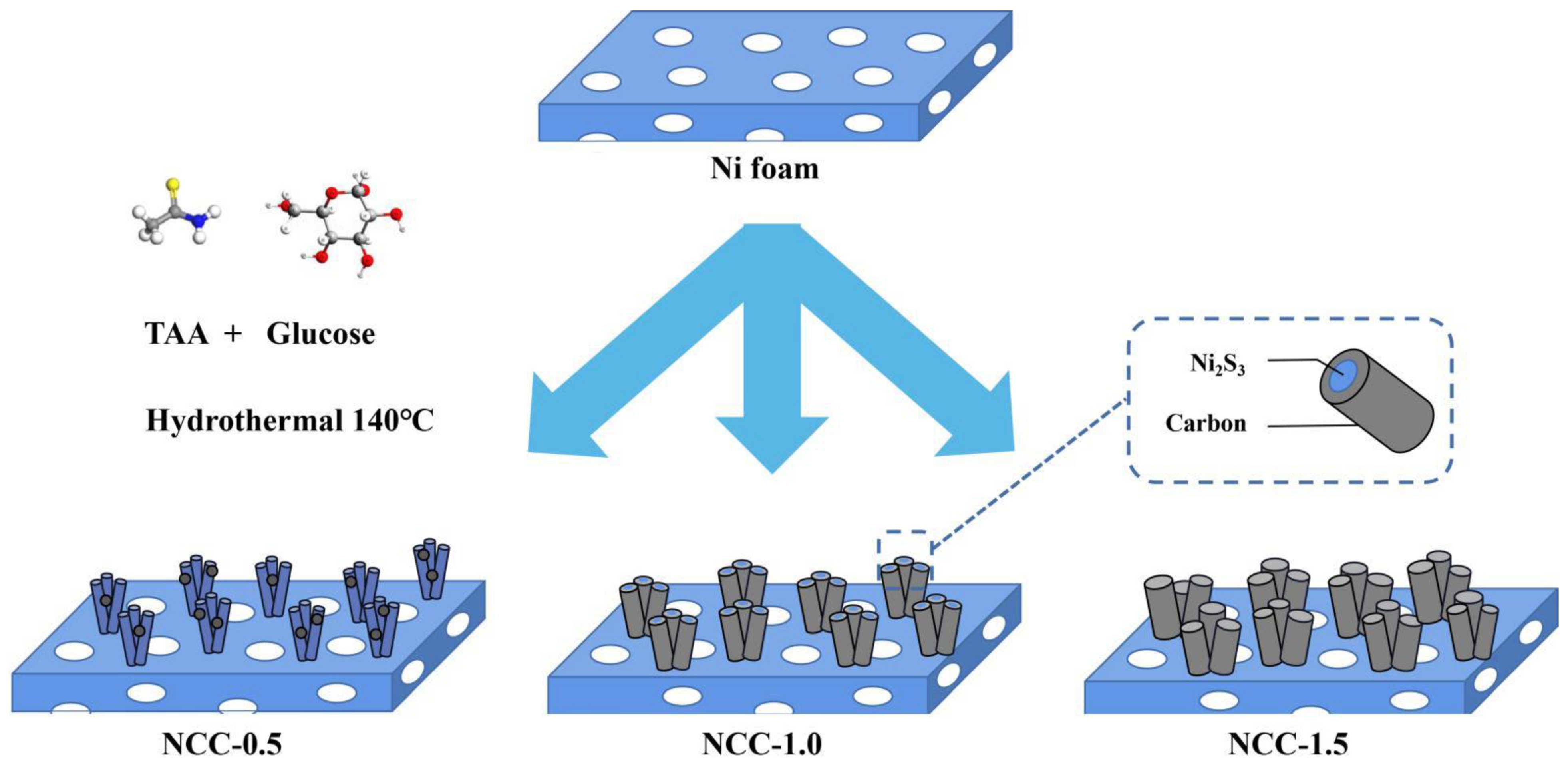
2.2. The Preparation of NCC-0.5/1/1.5

NCC-0.5/1/1.5 was prepared via a similar procedure. A piece of nickel foam with a size of 1 cm2 was treated by a 3 M HCl, acetone and distilled water to remove the contamination on the surface, subsequently, 10 mmol CH4N2O, 8 mmol TAA along with a certain quantity of glucose was added into 50 ml DMF solution under constantly stirring for 10 min (with the glucose mass of 0.5 g; 1 g and 1.5 g, corresponding to the concentration of 10 L−1, 20 L−1 and 30 L−1). Then, the mixture was transferred into 100 mL Teflon-lined stainless-steel autoclave, and keeping the temperature at 160 ℃ for 8 h. After cooling down to room temperature, the sample was washed and dried for 12 h to obtain Ni3S2 carbon coated structure (noted as NCC-0.5; NCC-1 and NCC-1.5, respectively).

2.3. Characterization of Samples

X-ray diffraction (XRD) was performed on a X-ray diffractometer (PANalytical-Empyrean, Panalytical, Amsterdam, The Netherlands) with Cu Ka radiation (λ = 0.15406 nm) at a scanning speed of 2 min−1. Scanning Electron Microscope (SEM,JSM5800, FEI, Hillsboro, OR, USA) and transmission electron microscopy (TEM, JEM2010, JEOL, Tokyo, Japan) was employed to investigate the surface microtopography of the material. Raman spectrum was characterized via Laser Raman Spectrometer(Autosor-iQ, Jobin Yvon, Paris, France). Dispersive spectrometry (EDS) were executed via Oxford INCA model 7421 energy dispersion spectrometer(AZtec X-Max 80, Oxford Instrument, Oxford, UK). Specific area of the sample was confirmed through Brunauer-Emmett-Teller (BET) approach(Autosor-iQ, Quantanchrome instruments, Boynton, the United States).

2.4. Electrochemical Tests

All the electrochemical tests was proceed by three-electrode cell workstation (CHI 660E, Chenhua, Shanghai) in 3 M KOH aqueous solution while platinum sheet was served as counter electrode, as-obtained nickel sulfide was as positive electrode material and saturated calomel electrode (SCE) was as reference electrode. CV (cyclic voltammetry), GCD (galvanostatic charge-discharge) and EIS (electrochemical impedance spectroscopy) and cycling stability tests was executed to investigate the electrochemical properties. Mass specific capacitance (Cm) can be calculated by the following equation [30]:
Cm = I × t/m × U
where I(A) represent current conducted on electrode materials, t(s) stands for the discharging time, m(g) signifies active mass of the electrode, and U(V) refers to the discharge potential window.
HSC (hybrid supercapacitor) device was fabricated, NCC-1 as a battery-type positive electrode while active carbon (AC) was as negative electrode, samples was cut into round shape with the radius of 0.5 cm in order to fit the cell, AC and polyvinylidene fluoride (PVDF) was mixed with of mass ratio of 9:1, then uniformly coated on Ni foam to obtain a AC negative electrode. Finally, the positive and negative electrode were put into the button cell using 1 M KOH, filter as electrolyte, and a separator for assembling the device. The specific energy and specific power were calculated via the formula:
E = 0.5 × Cm × U2/3.6
P = 3600 × E/t
where U(V) present voltage window, Cm(C/g) imply the specific capacity, t(S) signifies the discharging time.

3. Results and Discussion

The preparation of NCC-0.5/1/1.5 rod-like structure was shown in Figure 1, first, the Ni foam was directly used as the Ni source and substrate, TAA (thioacetamide) was added as S source, glucose was as C source. Finally, NCC was grown on the Ni surface though hydrothermal sulfidization and self carbon-coating process, Ni3S2 nanowires was first synthesized from the hydrothermal process, then, the carbon material was wrapped on the Ni3S2 nanowires, forming a well-defined core-shell heterostructure. The growing process of nickel sulfide and the carbon coating step are integrated within a facile one-pot hydrothermal method, simplifying the reaction steps without calcination and other subsequent processing.
SEM images of NCC-0.5/1/1.5 and bare Ni3S2 in different magnification was shown on Figure 2a–d, it can be seen that, bare Ni3S2 nanowires were uniformly grown on the Ni foam, which could act as scaffolds for the subsequent growth of carbon shell. As-obtained Ni3S2 sample directly growing on the substrate demonstrates rod-like structure with the width of nearly 500 nm. While the high magnification image shows the controlled growth of NiS2 in one plane. Figure 2c,d exhibits carbon coated Ni3S2 rod-like structure, which can be seen that, through one-pot hydrothermal process, the carbon layer was uniformly wrapped on the sulfide surface. the rods are well-aligned and remain the similar morphology before and after carbon coating. The introduction of carbon was found to be helpful in controlling the grain growth of overall structure suggesting that there was no irregular growth, and all the structures were of uniform size.
To investigate the effect of glucose concentration to carbon layer, the morphology of NCC structure with different mass ratio of glucose is further analyzed in Figure 3a–c. By regulating the concentration of the glucose, we obtained samples coated with different amount of carbon, as to Figure 3b, it is identified that the shape and size of the nanowires are not much altered even after carbon coating. When the glucose precursor concentration is relatively low (10 g L−1), glucose pellets were uniformly distributed on the surface of nanowires (Figure 3a). If the concentration reaches a relatively high level (30 g L−1), the carbon layer not only coated the nanowires, but also generated excessive carbon on the surface of the sample, resulting in a change in the morphology of the sample (Figure 3c). The carbon layer can be uniformly coated on the surface of the as-prepared sample (Figure 3b) only when the glucose concentration is suitable (20 g L−1). Moreover, transmission electron microscope (TEM) tests were also employed to analyze the internal structure of the materials, as can be seen from Figure 3d,e, a single Ni3S2@Carbon nanowires was prepared, Ni3S2 encapsulated by carbon layer have the average diameter of 80 nm, the thickness of outer amorphous carbon layer is approximately 20 nm. In addition, HRTEM image reveals well-resolved lattice fringes of 0.29 nm, which correspond to the typical (110) crystal planes of Ni3S2.
The energy dispersive spectrometer test (EDS) for Ni, S, and C were also conducted to explore the elemental distribution of the material. From Figure 3f, the material consisted of these three elements above. Meanwhile, the atomic percentage of the element Ni and S is 45.4:19.6, which is very close to 3:2, indicating we have successfully prepared Ni3S2@Carbon material.
Figure 4a shows the XRD patterns of NCC-0.5, NCC-1 and NCC-1.5, for the XRD pattern of NCC, the diffraction peaks at 23.4°, 33.5°, 47.9°, 53.8°, 54.2°, and 75.4° can be attributed to the (101), (110), (202), (113), (211), and (131) planes of hexagonal Ni3S2 (JCPDS 44-1418), respectively, indicating the presence of crystalline Ni3S2. However, the presence of carbon was not clearly detected on image, which could possibly because of too much weak to obvious. Other characters such as the SEM, EDS mapping, and XPS measurements confirmed the presence of carbon. Moreover, it is known that XRD diffraction peak is corresponding to a certain crystal surface, higher intensity indicating the abundant array of atoms on the material surface, and larger number of surface atoms lead to higher crystallization. As a result, as for the NCC-0.5, NCC-1 and NCC-1.5, there is no significant difference in peak intensity, but bare Ni3S2 has the highest intensity, which is because the combination of nickel sulfide and amorphous carbon reduces the crystallinity of the material, leading to lower intensity of NCC-0.5/1/1.5.
XPS was undertaken to analyze the valence state of the elements. Figure 4b presents the C 1s spectrum, exhibits three-type peaks at 284.7, 285.4, and 287.4, which are respectively attributable to C–C/C–O, C=O bonds [31]. From Figure 4c, The spectrum of N 2p is divided into four components peaks at 855.8, 861.7, 873.7 and 880 eV, two main peaks and two satellite peaks can be observed in Ni region, the two main peaks at 855.7 and 873.7 eV are belong to 2p 3/2 and 2p1/2, respectively, while two peaks located at 861.7 eV and 880 eV are belong to satellite peaks.
Raman spectra were recorded for bare and carbon-coated Ni3S2(NCC-1) and are presented in Figure 4d. On the account of strong intensity of carbon peak, in order to improve the measurement accuracy, we set a small Raman shift range of 100–500 cm−1 to NCC-1. The small image inserted in the Figure 4d reveals an obvious Ni3S2 peak, demonstrating the presence of nickle sulfide. Meanwhile, obvious difference between bare and NCC-1 can also be seen, both patterns exhibited the characteristic bands at 187, 201, 222, 303, 324, 350 cm−1. The observed Raman bands are consistent with the previous reports on Ni3S2 [32,33,34]. In addition to the above characteristic bands, NCC-1 clearly reveals the existence of carbon with its two characteristic bands at 1330 and 1513 cm−1. The band at 1513 cm−1 corresponds to the G band, whereas the broad band (D) at 1330 cm−1 is related to the disordered carbon. The peak intensity ratio of D and G bands (ID/IG) provides information about the degree of crystallinity of the carbon covered on the Ni3S2. In the present case, the ID/IG ratio is 0.83, depicting a typical amorphous carbon structure, which agrees well with the XRD and TEM measurements [35].
N2 adsorption–desorption isotherm of NCC-1.5, NCC-0.5 and NCC-1 are also investigated via Figure 5, it can be seen that the specific area of NCC-1.5, NCC-0.5 and NCC-1 reached 29.95 m2/g, 80.56 m2/g, and 231 m2/g, respectively, indicating that NCC-1 possess largest specific area. which are consistent with the microscopical observation of as-prepared NCC-1. Note that the large specific surface areas brought by the carbon coating will undoubtedly shorten the ion diffusion paths and enhance the utilization of active materials, which can contribute to an improved pseudocapacitive performance.
The electromechanical test of the obtained sample is shown in Figure 6 and Figure 7. Figure 6 illustrates, CV (Cyclic voltammetry) curves at the scan rate of 10 mV s−1 and GCD (galvanostatic charge-discharge) curves under the current density of 1 A g−1 of NCC-1.5, NCC-0.5, and NCC-1. From the images of CV curves, the as-obtained sample shows redox peaks evidencing the typical Faradaic pseudocapacitance behavior. Moreover, covering area of the NCC-1 is larger than that of NCC-1.5 and NCC-0.5, revealing a better electrochemical performance of NCC-1. The observed redox peaks are assumed to be reversible electron transfer process occurred on the surface of the Ni3S2 electrodes by the equation:
Ni3S2 + 3OH = Ni3S2(OH) 3 + 3 e
Corresponding to the CV test, GCD curves of three electrodes are shown in Figure 6b, discharging time of NCC-1 reaching 657s, which is longer than that of NCC-0.5 (503s), NCC-1.5 (548 s) and bare Ni3S2 (616 s), resulting the capacity of 657 C g−1, 503 C g−1 548 C g−1 and 616 C g−1, respectively (calculation method is according to the Equation (1)). CV curves at various scan rate and GCD curves with different current density of sample NCC-1 was demonstrated in Figure 6c,d), it can be seen that as the scan rate increased, the cathodic peak moves to negative direction and the anodic peak position moves to positive direction while CV curves remain similar shape, which revealing excellent rate performance of NCC-1. From the Figure 6d, GCD curves of NCC-1 with various current density was investigated, the obvious platform exhibited on the image evidencing the representative battery-type behavior which derived from the redox reaction occurred on the interface. In the current density of 1 A g−1, NCC-1 present discharging time of 657 s, corresponding capacitor of 657 C g−1 with 1 mg of mass of active martial. Even at the high density of 10 A g−1, the capacity still shows capacity retention of 83.2% to its value in 0.5 A g−1.
For comparison, plot diagram of NCC-0.5, NCC-1.5 and NCC-1 was further explored in Figure 7a, The as-obtained samples demonstrated similar capacity retention of 78.4% (NCC-0.5), 64.7% (NCC-1.5) 83.2% (NCC-1) and 50.2% (bare Ni3S2) (from 0.5 A g−1 to 10 A g−1), such great rate ability can be attributed to the unique nanorods arrays structure directly growing on the Ni substrate without the addition of binder or conductive material and the improvement of electrical conductivity brought by carbon coating. Nyquist plots of EIS was carried out in Figure 7b to investigating electrochemical behavior, as can be seen, intercept at the real axis (Z0) represent the combined resistance (Rs) between electrode and electrolyte, NCC-1 and NCC-1.5 present smallest intercept, which indicates good electrical conductivity. Furthermore, the plot displays a nearly vertical line in the low frequency region, which is the evidence of relatively low ionic diffusion resistances of the NCC-1. The semicircle represents charge transfer resistance (Rct) caused by Faradic reactions, and the smaller diameter size of NCC-1 suggesting lower combined resistance than that of NCC-1.5 and NCC-0.5. Meanwhile, cycling stability test was conducted via GCD measurement within a constant current density of 5 A g−1 over 3500 cycles, the result present the decline of the specific capacitance with the retention of 76.7% of its original value, demonstrating enhanced cycling ability than bare Ni3S2. The improvement of stability is due to the improvement of electronic conduction characteristics of the composites by carbon-sulfide materials, the carbon layer on the surface of the sample protects the inner layer, which weakens and limits the damage caused by expansion stress to the material structure during the charge and discharge period.
Table 1 compares the electrochemical properties and synthesizing method for different Ni3S2@carbon composites. The results reveal the enhanced specific capacity, best rate performance, and excellent cycling stability of as-obtained NCC-1. The improvement to the properties can be attributed to the shorter diffusion path and synergistic effect between materials.
To analyze the practical application of NCC-1 as battery-type electrode. Figure 8a reveal the schematic diagram for the assembling process, HSC (NCC-1//AC) device was fabricated, consisting of NCC-1 as a positive electrode while AC@NF as negative electrode and filter as separator in KOH electrolyte. Figure 8b depicts a comparison for the CV curves of NCC-1 and AC under the scan rate of 10 mv s−1, from the image, CV curves of AC demonstrates a rectangle shape, which implying the typical behavior of EDLC. Moreover, NCC-1 and AC electrode present disparate potential window of −1–0 V and 0–0.8 V, respectively. Different voltage windows of positive and negative electrode resulting a wider range of operating voltages, thus improving the specific energy of the device.
In order to investigate maximal operating potential range, CV and GCD measurement of the device at various potential window was exhibits in Figure 8c,d, CV and GCD test was carried at the scan rate/current density of 30 mv s−1 and 1 A g−1, respectively. It can be seen that the potential window gradually increased, general shape of the curves remain unchanged, indicating the maximum potential of 1.55 V. The electrochemical properties of HSC device was further verified through CV and GCD measurement at different scan rates and current densities, from Figure 8e,f, as the scan rate elevates, CV curves still retain similar form, GCD curves exhibits symmetrical shape and an obvious plateau, reach a potential of 1.55 V, implying a faradic battery-type behavior. Specific capacitance of the device was plotted in Figure 8g, calculated at 255 F g−1 at 1 A g−1 and maintained 58.8% of its initial capacitance even the current density elevated to 3.6 A g−1 (the sudden capacity increasing might be caused by the shedding of carbon layer during charge-discharge process, exposing more capacitive sulfide material). Figure 8h depicts the Ragone plot of device’s specific energy and specific power, as-obtained device exhibits highest specific energy of 88.7 Wh kg−1 at the specific power of 775 W kg−1 and still kept an specific energy of 50.33 Wh kg−1 even when the specific power reached up to 2790 W kg−1. Cycling stability test was performed after 5000 cycles and the device demonstrates great stability with a capacitance retention ratio of 68.97%.

4. Conclusions

In this work, we have successfully prepared a rod-like Ni3S2@carbon structure by the one-pot hydrothermal method. A different morphology was controlled by modulating various concentration of glucose and the as-prepared Ni3S2 carbon coating rod arrays exhibits best electrochemical property when the glucose concentration is 20 g L−1, with the high specific capacity of 657 C g−1 at the current density of 1 A g−1, and with excellent stability of 76.7% retention after 3500 cycles. Moreover, an HSC device was fabricated and the as-obtained device demonstrated a high specific energy of 88.7 Wh kg−1 at the specific power of 775 W kg−1. The facile strategy for directly using Ni foam as substrate and Ni source with a simple one-step hydrothermal method can provide a protocol for the fabrication of high-performance supercapacitors.

Author Contributions

Conceptualization, Z.W.; investigation, Z.W.; validation, Z.W.; writing—original draft preparation, Z.W.; writing—review and editing, W.X. and H.H. (Haifu Huang); methodology, W.X.; investigation, H.H. (Haifu Huang); data curation, H.H. (Huanhuan Huang); formal analysis, Y.Z.; resources, S.Y.; data curation, W.Z.; software, Z.C.; supervision, J.W.; project administration, G.L. All authors have read and agreed to the published version of the manuscript.

Funding

This research was supported by the fund of State Key Laboratory of Crystal Materials, Shandong University (KF2012). Project (11604147) supported by the National Natural Science Foundation of China; Project (M32048) supported by the Foundation of National Laboratory of Solid State Microstructures, China; Project (20142BBE50014) supported by the Jiangxi Province Key Projects of Science and Technology Support Plan, China.

Data Availability Statement

3rd Party Data Restrictions apply to the availability of these data. Data was obtained from Nanchang University and are available from the authors with the permission of Nanchang University.

Acknowledgments

The authors express their sincere thanks to the Nanchang University and the financial assistance from the National Natural Science Foundation of China; Project (M32048).

Conflicts of Interest

The authors declare that they have no known competing financial interests or personal relationships that could have appeared to influence the work reported in this paper.

References

  1. Chang, Y.; Sui, Y.; Qi, J.; Jiang, L.; He, Y.; Wei, F.; Meng, Q.; Jin, Y. Facile synthesis of Ni3S2 and Co9S8 double-size nanoparticles decorated on rGO for high-performance supercapacitor electrode materials. Electrochim. Acta 2017, 226, 69–78. [Google Scholar] [CrossRef]
  2. Yang, Z.; Zhang, J.; Kintner-Meyer, M.C.; Lu, X.; Choi, D.; Lemmon, J.P.; Liu, J. Electrochemical energy storage for green grid. Chem. Rev. 2011, 5, 3577–3613. [Google Scholar] [CrossRef] [PubMed]
  3. Yu, Z.; Tetard, L.; Zhai, L.; Thomas, J. Supercapacitor electrode materials: Nanostructures from 0 to 3 dimensions. Energy Environ. Sci. 2015, 8, 702–730. [Google Scholar] [CrossRef] [Green Version]
  4. Zhai, Y.; Dou, Y.; Zhao, D.; Fulvio, P.F.; Mayes, R.T.; Dai, S. Carbon materials for chemical capacitive energy storage. Adv. Mater. 2011, 23, 4828–4850. [Google Scholar] [CrossRef] [PubMed]
  5. Li, B.; Zheng, M.; Xue, H.; Pang, H. High performance electrochemical capacitor materials focusing on nickel based materials. Inorg. Chem. Front. 2016, 3, 175–202. [Google Scholar] [CrossRef]
  6. Lai, F.; Miao, Y.E.; Huang, Y.; Chung, T.S.; Liu, T. Flexible hybrid hembranes of NiCo2O4-doped carbon nanofiber@mno2 core-sheath nanostructures for high-performance supercapacitors. J. Phys. Chem. C 2015, 119, 13442–13450. [Google Scholar] [CrossRef]
  7. Yu, X.Y.; Yu, L.; Lou, X.W. Metal sulfide hollow nanostructures for electrochemical energy storage. Adv. Energy Mater. 2016, 6, 1501333. [Google Scholar] [CrossRef]
  8. Chen, W.; Xia, C.; Alshareef, H.N. One-step electrodeposited nickel cobalt sulfide nanosheet arrays for high-performance asymmetric supercapacitors. ACS Nano 2014, 8, 9531–9541. [Google Scholar] [CrossRef] [PubMed]
  9. Khan, A.; Senthil, R.A.; Pan, J.; Osman, S.; Sun, Y.; Shu, X. A new biomass derived rod-like porous carbon from tea-waste as inexpensive and sustainable energy material for advanced supercapacitor application. Electrochim. Acta 2020, 335, 135588. [Google Scholar] [CrossRef]
  10. Choi, J.W.; Aurbach, D. Promise and reality of post-lithium-ion batteries with high energy densities. Nat. Rev. Mater. 2016, 1, 16013. [Google Scholar] [CrossRef]
  11. Yang, V.; Senthil, R.A.; Pan, J.; Kumar, T.R.; Sun, Y.; Liu, X. Hierarchical porous carbon derived from jujube fruits as sustainable and ultrahigh capacitance material for advanced supercapacitors. J. Colloid Interfaces Sci. 2020, 579, 347–356. [Google Scholar] [CrossRef] [PubMed]
  12. Abdalla, A.M.; Sahu, R.P.; Wallar, C.J.; Chen, R.; Zhitomirsky, I.; Puri, I.K. Nickel oxide nanotubes synthesis using multiwalled carbon nanotubes as sacrificial templates for supercapacitor application. Nanotechnology 2016, 28, 075603. [Google Scholar] [CrossRef]
  13. Xing, Z.; Chu, Q.; Ren, X.; Ge, C.; Qusti, A.H.; Asiri, A.M.; Al-Youbi, A.O.; Sun, X. Ni3S2 coated ZnO array for high-performance supercapacitors. J. Power Sources 2014, 245, 463–467. [Google Scholar] [CrossRef]
  14. Zhou, W.; Cao, X.; Zeng, Z.; Shi, W.; Zhu, Y.; Yan, Q.; Liu, H.; Wang, J.; Zhang, H. One-step synthesis of Ni3S2 nanorod@ Ni(OH)2 nanosheet core–shell nanostructures on a three-dimensional graphene network for high-performance supercapacitors. Energy Environ. Sci. 2016, 6, 2216–2221. [Google Scholar] [CrossRef] [Green Version]
  15. Pereira, M.C.; Pereira, M.L.; Sousa, J.P. Evaluation of nickel toxicity on liver, spleen, and kidney of mice after administration of high-dose metal ion. J. Biomed. Mater. Res. 1998, 40, 40–47. [Google Scholar] [CrossRef]
  16. Gao, M.R.; Xu, Y.F.; Jiang, J.; Yu, S.H. Nanostructured metal chalcogenides: Synthesis, modification, and applications in energy conversion and storage devices. Chem. Soc. Rev. 2013, 42, 2986–3167. [Google Scholar] [CrossRef]
  17. Zhang, F.; Xiao, F.; Dong, Z.H.; Shi, W. Synthesis of polypyrrole wrapped graphene hydrogels composites as supercapacitor electrodes. Electrochim. Acta 2013, 114, 125–132. [Google Scholar] [CrossRef]
  18. Liu, Y.; Zhang, Y.; Ma, G.; Wang, Z.; Liu, K.; Liu, H. Ethylene glycol reduced.graphene oxide/polypyrrole composite for supercapacitor. Electrochim. Acta 2013, 88, 519–525. [Google Scholar] [CrossRef]
  19. Zhang, D.; Sun, W.; Zhang, Y.; Dou, Y.; Jiang, Y.; Dou, S.X. Engineering hierarchical hollow nickel sulfifide spheres for high-performance sodium storage. Adv. Funct. Mater. 2016, 26, 7479–7485. [Google Scholar] [CrossRef] [Green Version]
  20. Peng, S.; Li, L.; Tan, H.; Cai, R.; Shi, W.; Li, C.; Mhaisalkar, S.G.; Srinivasan, M.; Ramakrishna, S.; Yan, Q. MS2(M ¼ Co and Ni) hollow spheres with tunable interiors for high-performance supercapacitors and photovoltaics. Adv. Funct. Mater. 2014, 24, 2155–2162. [Google Scholar] [CrossRef]
  21. Shi, Z.; Xing, L.; Liu, Y.; Gao, Y.; Liu, J. A porous biomass-based sandwich-structured Co3O4@ carbon fiber @Co3O4 composite for high-performance supercapacitors. Carbon 2018, 129, 819–825. [Google Scholar] [CrossRef]
  22. Lin, H.; Liu, F.; Wang, X.; Ai, Y.; Yao, Z.; Chu, L.; Han, S.; Zhuang, X. Graphene-coupled flower-Like Ni3S2 for a free-standing 3D aerogel with an ultra-high electrochemical capacity. Electrochim. Acta 2016, 191, 705–715. [Google Scholar] [CrossRef]
  23. Xiao, S.; Huang, J.; Lin, C.; Xie, A.; Lin, B.; He, L.; Sun, D. Porous carbon derived from rice husks as sustainable bioresources: Insights into the role of micro/mesoporous hierarchy in Co3O4/C composite for asymmetric supercapacitors. Microporous Mesoporous Mater. 2020, 291, 1387. [Google Scholar] [CrossRef]
  24. Yang, B.; Yu, L.; Liu, Q.; Liu, J.; Yang, W.; Zhang, H.; Wang, F.; Hu, S.; Yuan, Y.; Wang, J. The growth and assembly of the multidimensional hierarchical Ni3S2 for aqueous asymmetric supercapacitors. CrystEngComm 2015, 17, 4495–4501. [Google Scholar] [CrossRef]
  25. Yin, Q.; He, L.; Lian, J.; Sun, J.; Xiao, S.; Luo, J.; Sun, D.; Xie, A.; Lin, B. The synthesis of Co3O4/C composite with aloe juice as the carbon aerogel substrate for asymmetric supercapacitors. Carbon 2019, 155, 147–154. [Google Scholar] [CrossRef]
  26. Xia, X.; Zhu, C.; Luo, J.; Zeng, Z.; Guan, C.; Ng, C.F.; Zhang, H.; Fan, H.J. Synthesis of free-standing metal sulfide nanoarrays via anion exchange reaction and their electrochemical energy storage application. Small 2014, 10, 766–773. [Google Scholar] [CrossRef]
  27. Ji, F.; Jiang, D.; Chen, X.; Pan, X.; Kuang, L.; Zhang, Y.; Alameh, K.; Ding, B. Simple in-situ growth of layered Ni3S2 thin film electrode for the development of high-performance supercapacitors. J. Appl. Surf. 2016, 99, 432–439. [Google Scholar]
  28. Shen, M.; Liu, J.; Liu, T.; Yang, C.; He, Y.; Li, Z.; Li, J.; Qian, D. Oxidant-assisted direct-sulfidization of nickel foam toward a self-supported hierarchical Ni3S2@Ni electrode for asymmetric all-solid-state supercapacitors. J. Power Sources 2019, 448, 227408. [Google Scholar] [CrossRef]
  29. Zhang, Z.; Huang, Z.; Ren, L.; Shen, Y.; Qi, X.; Zhong, J. One-pot synthesis of hierarchically nanostructured Ni3S2 dendrites as active materials for supercapacitors. Electrochim. Acta 2014, 149, 316–323. [Google Scholar] [CrossRef]
  30. Zhou, W.; Wu, X.J.; Cao, X.; Huang, X.; Tan, C.; Tian, J.; Liu, H.; Wang, J.; Zhang, H. Ni3S2 nanorods/Ni foam composite electrode with low overpotential for electrocatalytic oxygen evolution. Energy Environ. Sci. 2013, 6, 2921–2924. [Google Scholar] [CrossRef]
  31. Li, J.; Wang, S.; Xiao, T.; Tan, X.; Xiang, P.; Jiang, L.; Deng, C.; Li, W.; Li, M. Controllable preparation of nanoporous Ni3S2 films by sulfuration of nickel foam as promising asymmetric supercapacitor electrodes. Appl. Surf. Sci. 2017, 420, 919–926. [Google Scholar] [CrossRef]
  32. Zhong, J.H.; Wang, A.L.; Li, G.R.; Wang, J.W.; Ou, Y.N.; Tong, Y.X. Co3O4/Ni(OH)2 composite mesoporous nanosheet networks as a promising electrode for supercapacitor applications. J. Mater. Chem. 2012, 22, 5656–5665. [Google Scholar] [CrossRef]
  33. Yu, W.; Lin, W.; Shao, X.; Hu, Z.; Li, R.; Yuan, D. High performance supercapacitor based on Ni3S2/carbon nanofibers and carbon nanofibers electrodes derived from bacterial cellulose. J. Power Sources 2014, 272, 137–143. [Google Scholar] [CrossRef]
  34. Chen, J.S.; Guan, C.; Gui, Y.; Blackwood, D.J. Rational design of self-supported Ni3S2 nanosheets array for advanced asymmetric supercapacitor with a superior energy density. ACS Appl. Mater. Interfaces 2016, 9, 496–504. [Google Scholar] [CrossRef] [PubMed]
  35. Wang, W.; Xiao, Y.; Li, X.; Cheng, Q.; Wang, G. Bismuth oxide self-standing anodes with concomitant carbon dots welded graphene layer for enhanced performance supercapacitor-battery hybrid devices. J. Chem. Eng. 2019, 371, 327–336. [Google Scholar] [CrossRef]
  36. Liu, T.; Jiang, C.; Cheng, B.; You, W.; Yu, J. Hierarchical NiS/N-doped carbon composite hollow spheres with excellent supercapacitor performance. J. Mater. Chem. A 2017, 5, 1039. [Google Scholar] [CrossRef]
  37. Wen, J.; Li, S.; Zhou, K.; Song, Z.; Li, B.; Chen, Z.; Chen, T.; Guo, Y.; Fang, G. Flexible coaxial-type fiber solid-state asymmetrical supercapacitor based on Ni3S2 nanorod array and pen ink electrodes. J. Power Sources 2016, 324, 325–333. [Google Scholar] [CrossRef]
  38. Tian, Z.; Yin, J.; Wang, X.; Wang, Y. Construction of Ni3S2 wrapped by rGO on carbon cloth for flexible supercapacitor application. J. Alloys Compd. 2018, 777, 806–811. [Google Scholar] [CrossRef]
  39. Wu, P.; Wang, D.; Ning, J.; Zhang, J.; Feng, X.; Dong, J.; Hao, Y. Novel 3D porous graphene/Ni3S2 nanostructures for high-performance supercapacitor electrodes. J. Alloys Compd. 2018, 731, 1063–1078. [Google Scholar] [CrossRef]
  40. Dai, C.S.; Chien, P.Y.; Lin, J.Y.; Chou, S.W.; Wu, W.K.; Li, P.H.; Wu, K.Y.; Lin, T.W. Hierarchically structured Ni3S2/carbon nanotube composites as high performance cathode materials for asymmetric supercapacitors. ACS Appl. Mater. Interfaces 2013, 5, 12168–12174. [Google Scholar] [CrossRef]
  41. Wang, L.; Bo, M.; Guo, Z.; Li, H.; Huang, Z.; Che, H.; Feng, Z.; Wang, Y.; Mu, J. Construction of ultra-stable trinickel disulphide (Ni3S2)/polyaniline (PANI) electrodes based on carbon fibers for high performance flexible asymmetric supercapacitors. J. Colloid Interface Sci. 2020, 577, 29–37. [Google Scholar] [CrossRef] [PubMed]
Figure 1. Schematic illustration of the synthesis of Ni3S2 on Ni foam based to different temperature ranges.
Nanomaterials 11 00678 g001
Figure 2. SEM images of the Ni3S2 nanorods before and after carbon coating in different magnification: (a,b) bare Ni3S2 nanorods; (c,d) Ni3S2 carbon coating nanorods (NCC-1).
Nanomaterials 11 00678 g002
Figure 3. SEM images of (a) NCC-0.5, (b) NCC-1 and (c) NCC-1.5; HRTEM images of NCC-1 (d,e); EDS mapping of NCC-1 (f).
Nanomaterials 11 00678 g003
Figure 4. XRD patterns of NCC-0.5, NCC-1 and NCC-1.5 (a); C 1s spectrum (b); XPS patterns of (c) C1s and (d) Ni2p of NCC-1; Raman spectrum of bare Ni2S3 and NCC-1.
Nanomaterials 11 00678 g004
Figure 5. N2 adsorption–desorption isotherm of (a) NCC-1.5; (b) NCC-0.5; (c) NCC-1.
Nanomaterials 11 00678 g005
Figure 6. (a) Cyclic voltammetry curves and (b) charge-discharge curves of bare Ni3S2; NCC-0.5, NCC-1.5 and NCC-1 at the scan rate of 10 mV s−1 and in the potential window of 0.5 v and the current density of 1 A g−1; (c) Cyclic voltammetry curves and (d) charge-discharge curves of NCC-1.0 under various scan rate and current density.
Nanomaterials 11 00678 g006
Figure 7. (a) Specific capacity at different current density and (b) Nyquist plots of EIS of Ni3S2; NCC-1.5, NCC-1.0 and NCC-0.5; (c) Comparison of cycling stability test between bare Ni3S2 and NCC-1.
Nanomaterials 11 00678 g007
Figure 8. (a) Schematic diagram of the HSC device, (b) CV comparison curves of NCC-1 and AC electrodes, (c) CV curves and (d) GCD curves of NCC-1 in the potential range of 0.8–1.55 V at a scan rate of 50 mV s−1 at the current density of 1.0 A g−1, (e) CV curves and (f) GCD curves of NCC-1 device at various scan rates and current densities at the voltage window of 1.55 V, (g) Specific capacitance of the NCC-1 device in different current densities, (h) Ragone plot of the NCC-1 HSC device, (i) Cycling stability test of NCC-1 device.
Nanomaterials 11 00678 g008
Table 1. Method of synthesis, Specific capacity, Rate performance and Capacity retention of NCC-1 and other Ni3S2@Carbon materials reported in previous literatures.
MaterialsMethod of SynthesisSpecific Capacity (C g−1)/Current Density (A g−1)Rate Performance from 1 to 10 A g−1Capacity Retention/Cycles
NiS@N-doped carbon sphere [36]Multistep Transformation method517.5 C g−1/1 A g−178%76%/4000
Ni3S2@CNF [37]Hydrothermal380.6 C g−1/2 A g−183%88%/1500
Ni3S2@rGO [38]Vacuum filtration method477.37 C g−1/2 A g−176%88%/5000
Ni3S2@Graphene [39]CVD method372 C g−1/1 mv s−169.3%92.3%/5000
Ni3S2@CNT [40]Hydrothermal360 C g−1/3.2 A g−158.6%80%/1000
Ni3S2@PAN [41]Electrochemical deposition440 C g−1/1 A g−178.73%93.14%/2500
NCC-1 (this work)Hydrothermal657 C g1/1 A g−187.7%76.7%/3500
Publisher’s Note: MDPI stays neutral with regard to jurisdictional claims in published maps and institutional affiliations.

