Article

The Positive Temperature Coefficient of Resistivity in BiFeO3 Films

1
Department of Physics and Optoelectronics Engineering, Faculty of Science, Beijing University of Technology, Beijing 100124, China
2
School of Physics, Peking University, Beijing 100871, China
3
Institute of Microstructure and Properties of Advanced Materials, Beijing University of Technology, Beijing 100124, China
4
Institutes of Physical Science and Information Technology, Anhui University, Hefei 230601, China
*
Authors to whom correspondence should be addressed.
Nanomaterials 2022, 12(6), 892; https://doi.org/10.3390/nano12060892
Submission received: 9 February 2022 / Revised: 28 February 2022 / Accepted: 2 March 2022 / Published: 8 March 2022

Abstract

:
The use of lead-free ceramic film materials with positive temperature coefficient of resistivity (PTCR) is widespread in temperature heaters and sensors in micro-electromechanical systems. In this research, the out of plane transport properties of the BiFeO3 (BFO) films have been studied. Surprisingly, PTCR was found in the BFO ceramic films due to the strongly correlated interaction between the multiferroic material BFO and the superconductor YBCO perovskite oxides. To our knowledge, this is the first report on the PTCR effect of BFO films. The BFO/YBCO interface and the bulk conductivity of BFO are important for the PTCR effect, as they make it possible to compare the transport properties of Au/BFO/YBCO- and YBCO/BFO/YBCO-type structures. PTCR was observed in Au/BFO/YBCO at a bias voltage of more than 2 V, but not in the YBCO/BFO/YBCO, even with a 40 V bias voltage. PTCR was found after BFO breakdown of a YBCO/BFO/YBCO capacitor. This indicated that the conductivity of BFO is critical for PTCR. The dependence of PTCR on the superconducting transition temperature illustrates that a cooper-pair can be injected into BFO. Our work presents a method by which to produce a lead-free ceramic film material with PTCR.

1. Introduction

BiFeO3 (BFO) with a perovskite structure is a multiferroic material with the coexistence of magnetic order and ferroelectric order at room temperature [1,2]. BFO is usually combined with ferromagnetic [3,4] and superconductor [5,6,7] materials, because of the novel physical properties induced by the interaction between spin, charge and orbital. In this study, the multiferroic/superconductor BFO/YBCO heterostructure were investigated. The anomalous transport property, i.e., PTCR (Positive temperature coefficient of resistivity), was found. PTCR refers the increase of the resistance with an increase of temperature. PTCR is very useful in commercial equipment, because it can be used in self-contained, power-limiting devices to prevent failure induced by thermal runaway, usually owing to the grain boundaries [8]. Additionally, multiferroic materials may be used to reduce the electromagnetic interference generated by the excessive use of high-frequency electronic devices [9]. There are now mainly two kinds of materials with PTCR characteristics, namely, barium titanate series bulk materials [10,11,12] and vanadium oxide series bulk materials [13,14], both of which represent mature technologies.
In addition to bulk materials, film materials with PTCR characteristics are also important. For example, these materials can be used in surface heaters in MEMS to command the heaters and temperature sensors. To date, PTCR has been observed in BaTiO3 [15] and Pb(Ti, Zr)O3 [16] films. PTCR was found in BaTiO3 films in both ferroelectric and paraelectric states. Heywang et al. reported that the Curie temperature of BaTiO3 in the Pt/BaTiO3/IrO2 heterojunction was about 250 K. However, the observed temperature of PTCR effect is higher than 300 K, so BaTiO3 is in paraelectric state [17]. The PTCR effect occurs in BaTiO3 films when the applied voltage is greater than 2 V, and becomes notable with increases in applied voltage [17]. Those authors attributed the PTCR to the decreasing dielectric constant of BaTiO3 thin films with an increase of temperature [17].
In addition, Yang et al. reported that in Pt/BaTiO3/YBCO heterojunctions, BaTiO3 films exhibit a PTCR effect in the ferroelectric state, and a PTCR effect exists in both forward and reverse voltages of Pt [18]. This effect was attributed to the increase of dielectric constant. However, in contrast to paraelectric BaTiO3 film, the authors proposed that the increase in dielectric constant with decreasing the temperature was the direct cause of the PTCR effect. Meanwhile, Heywang et al. think that the increase of dielectric constant leads to an increase in the interfacial barrier and then PTCR effect. The temperature range of the PTCR effect is not fixed. As for the Pb(Ti, Zr)O3 films, a PTCR effect exists in the Au/Pb(Ti, Zr)O3/Nb-SrTiO3 heterostructure. The temperature range of this effect is 50 K–240 K [19]. PTCR is considered to be caused by tunneling through the Pb(Ti, Zr)O3/Nb-SrTiO3 interface.
For multiferroic BFO, the PTCR effect was observed in BFO nanoparticles [20] and bulks [21,22,23]. However, to the best of our knowledge, PTCR in BFO thin films has not been reported. In this paper, we report the PTCR in the BFO films at different temperature ranges for different top electrodes, within which BFO thin films are in a ferroelectric state. We will clarify the transport mechanism and identify the origins of this PTCR effect.

2. Materials and Methods

Multilayer films were fabricated by pulsed laser deposition. The SrTiO3(001) single crystalline substrate, the BiFeO3 and the YBCO target employed in this work were produced by Hefei Kejing Materials Technology Co. Ltd. of China. A commercial KrF excimer laser (Lambda Physik LPX-300, Gottingen, Germany; 248 nm, 20 ns) was used as a light source. The films were prepared using a pulsed laser deposition system (Model LMBE 450; SKY Company, Shenyang, China). The pulsed laser deposition method has the advantages of consistency of film composition with target composition, easy control of deposition conditions, high deposition rate and so on. The fabrication conditions are described elsewhere [24]. An image of the real heterostructure is shown in Figure 1.
The crystal structure was investigated by X-ray diffraction (XRD) using Cu Ka radiation (λ = 1.54056 Å). TEM characterization was performed on a FEI Tecnai F30 (FEI, Hillsboro, OR, USA) scanning transmission electron microscope. Cross-section TEM samples were prepared by focused ion beam. The superconducting and transport properties of the YBCO films were characterized by the standard four-point method. Oxygen vacancies were studied using a MICROLAB MK II X-ray photoelectron spectroscope (XPS, VG company, East Grinstead, England). The sample was introduced into the XPS system within 1 h after being removed from the deposition system. The vacuum of the analysis chamber was less than 3 × 10⁷ Pa. Using a 1253.6 eV Mg Ka line, the X-ray source operated at 14.5 kV. All the binding energies were corrected for the sample charging effect with reference to the C 1s line at 284.6 eV.

3. Results and Discussion

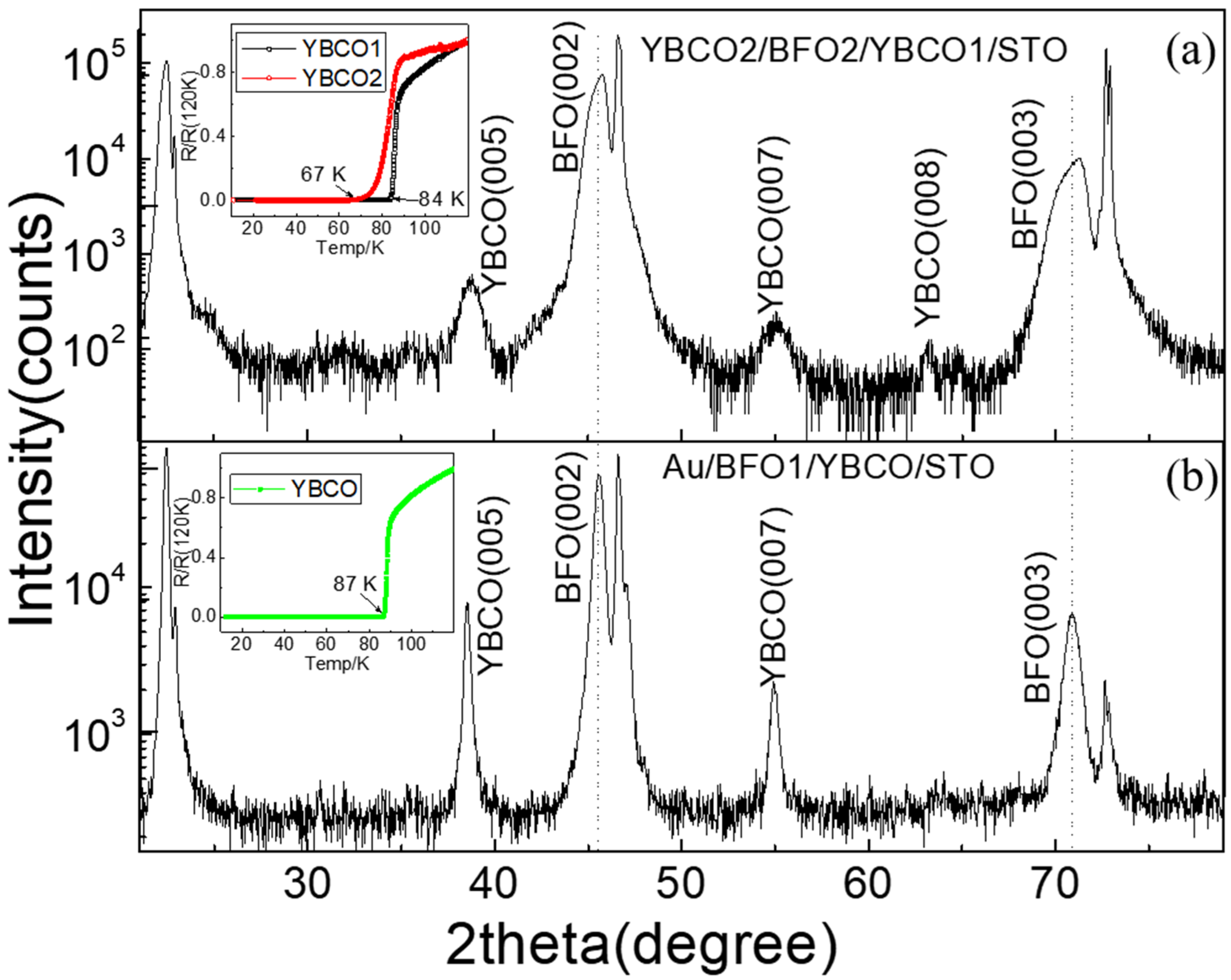
3.1. Structures in the BFO Capacitors
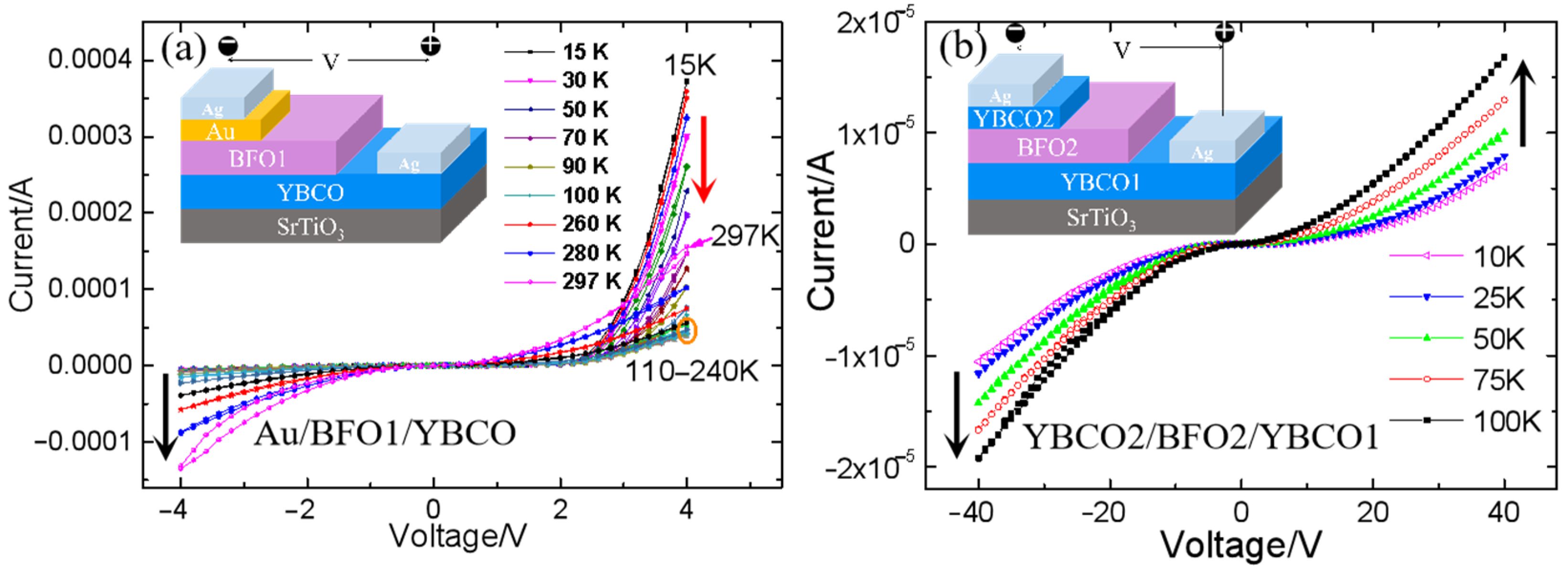
X-ray diffraction images of the YBCO2/BFO2/YBCO1 and Au/BFO1/YBCO capacitors are shown in Figure 2. The (001)-oriented diffraction peaks of YBCO and BFO may be clearly seen. No peaks of other phases are seen, indicating that the film underwent good crystallization. The BFO peaks in BFO2 shifted to the higher angle, exhibiting an increase of oxygen content compared to BFO1. The inserts of Figure 2 show the resistance versus temperature curves of YBCO1 and YBCO2 films. The superconducting transition temperature (TC) was 67 K for YBCO2, 84 K for YBCO1 in BFO2 capacitor and 87 K for YBCO in BFO1 capacitor.
TEM images of the two kinds of samples are shown in Figure 3, indicating the clear interface in the two BFO capacitors. According to the cross section TEM images, the thicknesses of films should be Au(40 nm)/BFO(150 nm)/YBCO(80 nm) and YBCO(70 nm)/BFO(220 nm)/YBCO(10 nm), respectively. Figure 3b, d show the HRTEM of the corresponding BFO in Figure 3a,c. The (001)-oriented growth of BFO may be observed. The FFT is shown in the insert of Figure 3b,d. It shows that there was no amorphous halo in the FFT, excluding the presence of amorphous phase. Figure 3c shows that more grain boundaries exist in the BFO2 than in the BFO1.

3.2. PTCR Effect

The PTCR effect was observed in Au/BFO1/YBCO heterostructures, as mentioned in one of our previous reports [24]. Nevertheless, the superconducting transition temperature of YBCO in this study was higher, i.e., 87 K, than that reported previously, i.e., 45 K. We analyzed the source of the PTCR effect and related factors by changing the preparation conditions and the top electrode. Firstly, the PTCR effect appeared in Au/BFO/YBCO; I–V curves of Au/BFO/YBCO in the temperature range of 15 K to 297 K are shown in Figure 4a. Because Au and YBCO have different work functions, there was a rectification effect in Au/BFO/YBCO. When YBCO was a positive voltage, the leakage current was large, and the PTCR effect emerged when the voltage was greater than 2 V. The current at 4 V decreased with a temperature increase from 15 K to 220 K, which meant that the resistance increased with increasing temperature, that is, PTCR. Additionally, PTCR was enhanced with increasing bias voltage, which is consistent with the phenomenon observed in BaTiO3 films [17]. Above 220 K, PTCR disappeared. The temperature range of PTCR matched that in Pb(Ti, Zr)O3 films [16]. However, the dielectric constant of BFO films did not increase with decreasing temperature in a temperature range of 50 K to 270 K [26], like the BaTiO3 films and Pb(Ti, Zr)O3 films. Therefore, the PTCR was not caused by the dielectric constant.
The transport current of the Au/BFO1/YBCO capacitor is determined by the characteristics of the two interfaces and the BFO bulk. The PTCR effect was observed in the Au/BFO1/YBCO capacitor at low temperature with a positively biased YBCO bottom electrode. As a comparison, we prepared a YBCO2/BFO2/YBCO1 capacitor and characterized its I–V characteristics at low temperature (as shown in Figure 4b). The top electrode of was changed to YBCO. The two electrodes were symmetrical in the YBCO2/BFO2/YBCO1 capacitor, so the rectification effect was not obvious. PTCR was not found in the YBCO2/BFO/YBCO1 capacitor. It can be seen from the curve that the current increased with an increase of temperature at a specific voltage, be it positive or negative voltage, without PTCR effect. The leakage current in the YBCO2/BFO2/YBCO1 capacitor was significantly smaller. No PTCR was observed even when the voltage increased to 40 V, that is, 10 times that in the Au/BFO1/YBCO capacitor. In most publications about PTCR, the authors suggest that the PTCR results from the grain boundaries of the bulk materials [27,28]. Nevertheless, Figure 3 illustrates that there are more grain boundaries in the BFO2 thin film than in the BFO1 film. Therefore, the grain boundaries are not critical for PTCR in our case. We think that the absence of PTCR in the YBCO2/BFO2/YBCO1 capacitor was caused by the preparation of top YBCO reducing the oxygen vacancy content in BFO, which reduced the leakage current and improved the insulation of BFO. The current in the YBCO2/BFO2/YBCO1 capacitor mainly came from thermal diffusion, so the current passing through the barrier increased with an increase of temperature.

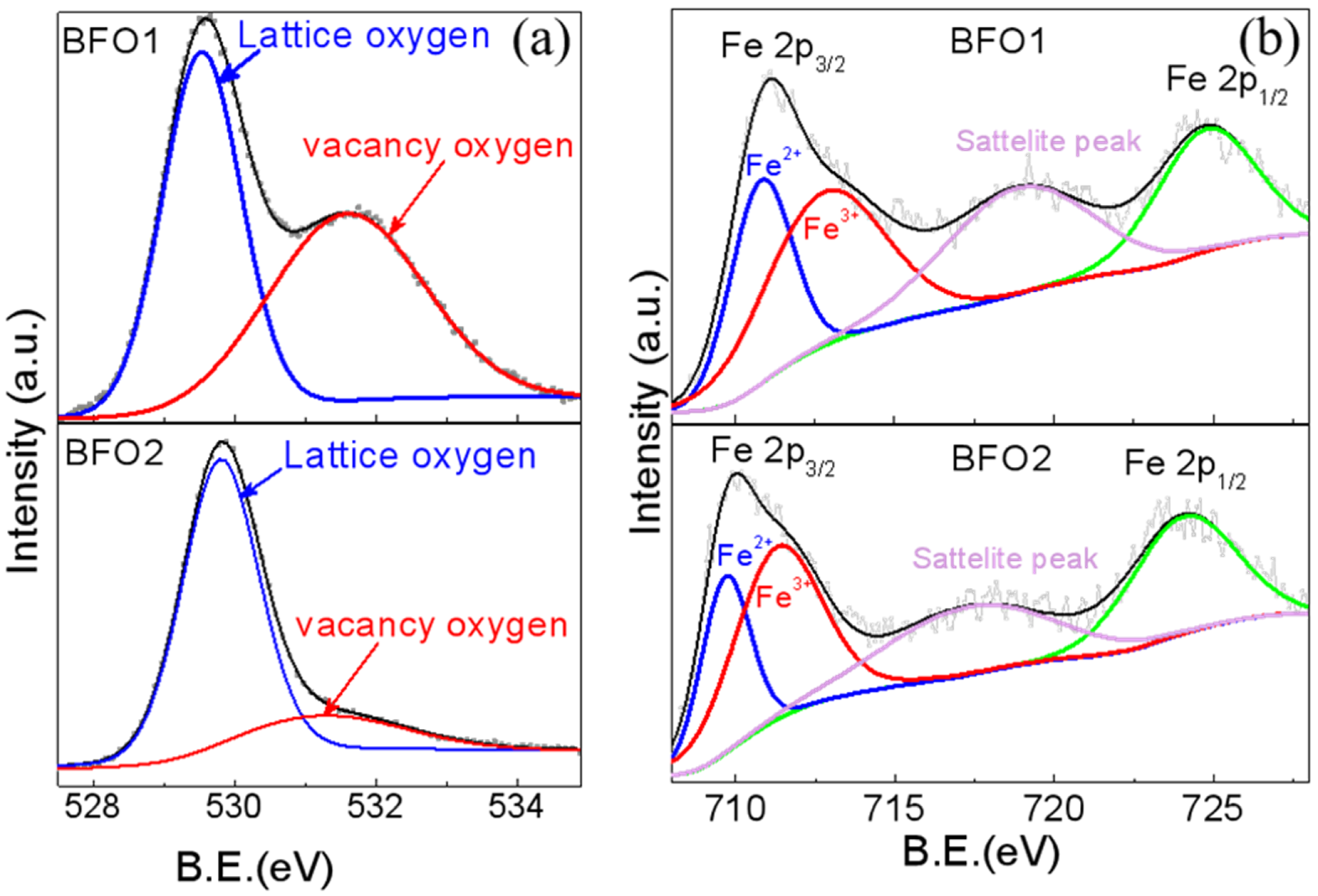
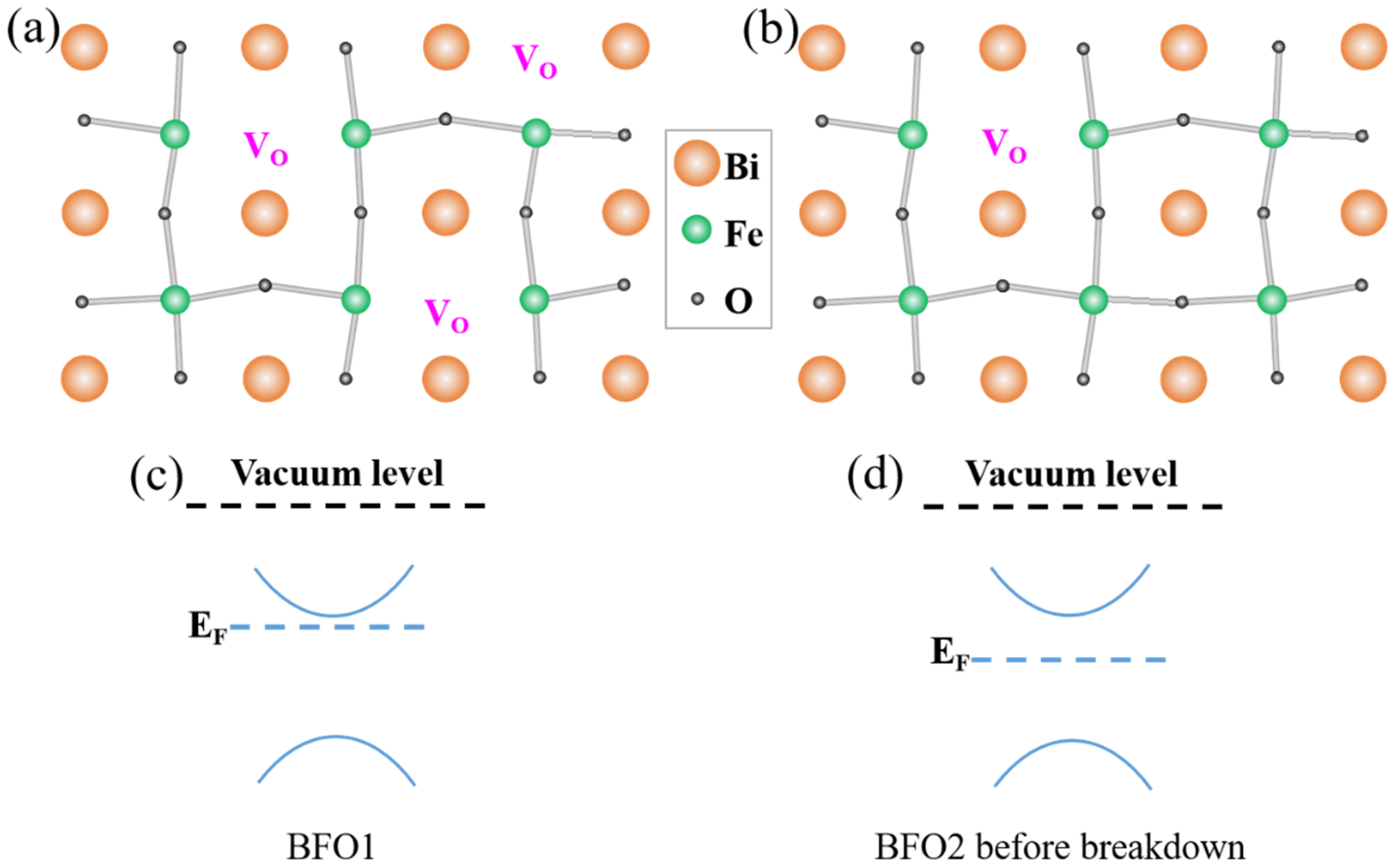
3.3. The Oxygen Vacancy Contents

The oxygen vacancy content in the two kinds of BFO capacitors was researched by X-ray photoelectron spectroscopy (XPS). When oxygen vacancies were present in the crystals, the surface chemical states changed, which could be both quantitatively and qualitatively explored by XPS. The XPS spectra for O 1s for BFO1 and BFO2 are presented in Figure 5a. The peak at roughly 529.5 eV (OI) in both samples was characteristic of O2−; this was associated with the chemical bonding between metal and oxygen [29]. Moreover, another XPS peak was observed at around 531.3 eV (OII). This was attributed to the existence of dangling bonds, owing to the formation of surface oxygen vacancies [30]. The relative content of oxygen vacancies could be quantitatively calculated by OI/ (OI + OII). According to this equation, the calculated oxygen vacancies contents were 49.9% and 20.2% for BFO1 and BFO2, respectively. The longer annealing time of the top electrode YBCO decreased the oxygen vacancy content in BFO. The leakage current also decreased, as shown in Figure 4.
The same conclusion can also be obtained from the XPS analysis of the Fe 2p peaks. Figure 5b shows that, for BFO, two Fe 2p peaks were observed at 710.2 eV and 724.3 eV, which corresponded to the feature peaks Fe 2p3/2 and Fe 2p1/2 of Fe3+. As there were more oxygen vacancies in BFO1 than in BFO2, the Fe 2p peaks shifted to the higher binding energy, i.e., a Fermi level shift [31,32]. This may be because oxygen vacancies increase the balance between electron density and binding energy [33]. The shift in Fermi level is commonly ascribed to the formation of oxygen vacancies, which would enlarge the equilibrium electron density, and thus, push the Fermi level upward [33]. Fe oxidation could be investigated by XPS. By fitting the peaks for the oxidation state of Fe ions in the XPS spectra, the Fe3+ in BFO1 was more than that in BFO2, which revealed the oxidation state in BFO1. The ratios of Fe2+ to Fe3+ in the BFO1 and BFO2 films were calculated as about 31:69 and 40:60, respectively. This demonstrated more oxygen vacancies in BFO1 compared to BFO2, as shown in Figure 6a,b.
It is well known that oxygen vacancies lead to more electron donors and enhance the donor density of semiconductors, and thus, their conductivity. By increasing the donor density, the transport current in BFO1 could be improved. The Fermi level of BFO1 could also be shifted toward the conduction band (as shown in Figure 6c). The oxygen vacancy content in the BFO2 film of YBCO2/BFO2/YBCO1 capacitor decreased. If the band gap increases, the Fermi level could be shifted toward the middle of the band gap, as shown in Figure 6d.
By comparing the transport properties in Au/BFO1/YBCO and YBCO2/BFO2/YBCO1 capacitors, it was revealed that the PTCR in BFO depends on the oxygen vacancy content. Oxygen vacancies enhanced the charge transport, which meant that PTCR occurred at a lower bias voltage. Therefore, the conductivity of BFO is important for PTCR. To check this result, a 200 V bias voltage was used to breakdown a BFO2 film. As expected, PTCR was observed in the BFO2 film after breakdown, as shown in Figure 7a. After breakdown, the current of BFO at low voltage (<10 V) increased by three orders of magnitude, while the current of BFO at 40 V increased by two orders of magnitude. The Fermi level could be shifted toward the conduction band to improve the conductivity of the BFO film. The PTCR in the BFO2 film after breakdown confirmed that it depended on the Fermi level and bulk conductivity.

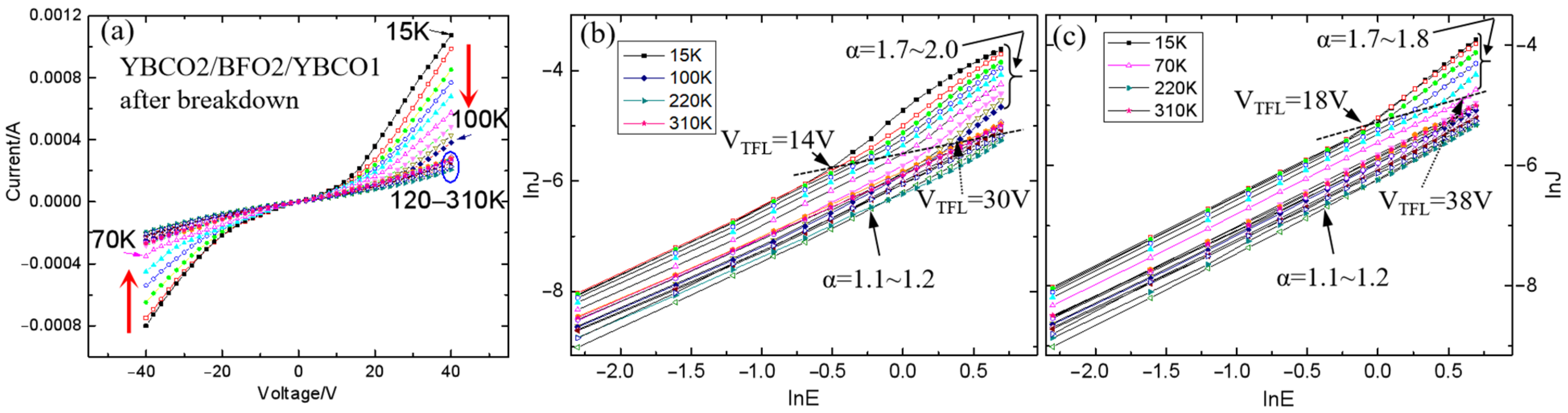
3.4. PTCR Effect in BFO/YBCO Capacitor after Breakdown

Unlike the Au/BFO1/YBCO capacitor, PTCR was detected in the YBCO2/BFO2/YBCO1 capacitor regardless of whether the YBCO1 bias was positive or negative, as shown in Figure 7a. Moreover, we found that the observed temperature of PTCR depended on TC, which was 100 K at positive bias and 70 K at negative bias. It should be noted that under positive bias, the BFO/YBCO1 interface was more critical in the charge transport than the YBCO2/BFO2 interface. The 84 K TC of YBCO1 was higher than that of YBCO2, i.e., 67 K. The higher TC of YBCO1 induced a larger temperature range of PTCR under positive bias. TC dependence of PTCR was also found in Au/BFO/YBCO capacitors. As the YBCO was positively biased, the current of the capacitor was higher than the negative bias, and the current was determined by the bulk BFO and the interface of BFO/YBCO. For the same BFO, a notable PTCR effect was observed below 100 K, as the TC of YBCO was 87 K, as shown in Figure 4a, and below 50 K for 45 K TC YBCO, as reported elsewhere [23]. Therefore, a higher superconducting transition temperature improves the temperature range of PTCR. PTCR depends not only on the bulk conductivity of BFO, but also on the superconducting transition temperature of YBCO. This was illustrated when a cooper-pair was injected into the BFO films. The phenomenon of a superconducting cooper-pair entering a superconductor-semiconductor structure has been reported previously [34,35]. However, more studies are required to understand the relation between the PTCR and the superconductivity of YBCO.
It is essential to understand the leakage current mechanism. The leakage current mechanism of Au/BFO1/YBCO has been discussed in our other articles [36]. Interface-limited Fowler-Nordheim tunneling was dominant in the Au/BFO1/YBCO capacitor at temperatures from 15 K to 80 K. Here, the leakage current mechanism of YBCO2/BFO2/YBCO1 after breakdown was investigated. Figure 7b,c show the plots of lnJ vs lnE for the YBCO2/BFO2/YBCO1 capacitor after breakdown with the YBCO1 electrode, both positively (Figure 7b) and negatively (Figure 7c) biased in a temperature range from 15 K to 310 K. It was observed that at low voltage (<14 V), the curve followed Ohmic behavior with the slope (α) value ~ 1. At a higher voltage (>14 V), the curve increased with α value ~ 2. The transport behavior of the BFO film resembled the bulk-limited Space-Charge-Limited Currents (SCLC) leakage mechanism. According to the SCLC model, the current density followed Child’s law [37]:
J = 9 8 ε r ε 0 μ E 2 L 3
where J is the leakage current density, εr is the relative dielectric constant, ε0 is the permittivity of free space, μ is the carrier mobility, E is the applied field and L is the film thickness. The key feature of the SCLC mechanism is the square relation between current and voltage.
At a low voltage, electrons from the electrodes or shallow traps near the thin film conduction band were injected into the conduction band to form Ohmic conduction. As the electric field increased, the number of electrons injected into the BFO increased, which exceeded the thermally stimulated density of electrons dominating SCLC conduction. The Child’s law for the SCLC model would be modified for
J E α ,   α > 1 .  
where J is the leakage current density, E is the applied field, α is the multiple slopes with exponent.
The transition voltage from Ohmic to modified Child’s law is called the trap limited voltage VTFL, which illustrates the voltage required to fill the deep electron traps. We found that VTFL changed from 14 V to 30 V as the temperature increased from 15 K to 100 K for the positively biased YBCO1. As for the negatively biased YBCO1, VTFL changed from 18 V to 38 V with increasing temperature from 15 K to 70 K. This indicates that deeper traps are found with increasing temperature [38,39]. The sample demonstrated PTCR in both Ohmic behavior and SCLC leakage mechanism region Therefore, the bulk nature of BFO thin films played an important role in the PTCR in our case, which was consistent with the previous analysis in this article. It is well known that the more traps, the greater the current. In our case, although the traps in the BFO films were suppressed as the temperature decreased, the current increased at the PTCR temperature range. This shows that bulk conductivity is the basic condition for, but is not the cause of, PTCR. Overall, the source of PTCR was the interface between BFO and YBCO.

4. Conclusions

In summary, we found an anomalous electrical transport property in BFO thin films, that is, a positive temperature coefficient effect of resistivity. PTCR was observed in BFO films at low temperature, within which BFO films were in a ferroelectric state. The source of PTCR in the BFO films was analyzed by changing the preparation conditions of the electrode. Firstly, the PTCR in BFO films depends on the bulk conductivity. The YBCO/BFO/YBCO heterostructure did not show any PTCR effect, but a notable PTCR was observed after the YBCO/BFO/YBCO had been broken down. After breakdown, the conductivity of the BFO film at the low voltage (<10 V) increased by three orders of magnitude, making it equivalent to that of BFO in a Au/BFO/YBCO capacitor. Secondly, the temperature range of PTCR in BFO films may be related to the superconducting transition temperature. For the Au/BFO/YBCO heterostructures, a notable PTCR effect was observed below 100 K and 50 K, as the superconducting transition temperature of YBCO is 87 K and 45 K, respectively. For the YBCO2/BFO/YBCO1 heterostructures, a notable PTCR effect was observed below 70 K and 100 K, as the superconducting transition temperature of YBCO2 and YBCO1 is 67 K and 84 K, respectively. Therefore, higher superconducting transition temperature increases the temperature range of PTCR. The conduction mechanism of YBCO/BFO/YBCO capacitors after breakdown was analyzed. It was found that it was more in line with the SCLC conduction mechanism. The sample exhibited PTCR in both low-voltage Ohmic behavior and high-voltage SCLC regions. The importance of superconductivity on PTCR was confirmed. However, more research is required to understand the relationship between PTCR and superconductivity. Our findings provide a new film material and research direction for the application of PTCR.

Author Contributions

Conceptualization, Q.Y. and H.Y.; methodology, Q.Y., X.W. and H.Y.; validation, Q.Y., Q.D. and R.N.; formal analysis, Q.Y., K.Y., J.D. and X.C.; investigation, Q.Y., R.N. and K.X.; data curation, Q.Y. and Q.D.; writing—original draft preparation, Q.Y.; writing—review and editing, X.W. and H.Y.; supervision, J.D., H.Y. and F.W.; funding acquisition, Q.Y., H.Y., J.D. and F.W. All authors have read and agreed to the published version of the manuscript.

Funding

This research was funded by the National Natural Science Foundation of China (project No. 11174010), the National Key Research and Development Program of China (2018YFB0703500), the Beijing Natural Science Foundation (project No. 3202001 and project No. 4192016), State Key Laboratory for Artificial Microstructure & Mesoscopic Physics (8102000344) and the Basic research fund project of Beijing university of technology (006000546317514).

Institutional Review Board Statement

Not applicable.

Informed Consent Statement

Not applicable.

Data Availability Statement

Data presented in this study are available on request from the first author.

Conflicts of Interest

The authors declare no conflict of interest.

References

  1. Wang, Y.; Jiang, Q.-H.; He, H.-C.; Nan, C.-W. Multiferroic BiFeO3 thin films prepared via a simple sol-gel method. Appl. Phys. Lett. 2006, 88, 142503. [Google Scholar] [CrossRef]
  2. Pakalniškis, A.; Lukowiak, A.; Niaura, G.; Głuchowski, P.; Karpinsky, D.V.; Alikin, D.O.; Abramov, A.S.; Zhaludkevich, A.; Silibin, M.; Kholkin, A.L.; et al. Nanoscale ferroelectricity in pseudo-cubic sol-gel derived barium titanate–bismuth ferrite (BaTiO3–BiFeO3) solid solutions. J. Alloys Compd. 2020, 830, 154632. [Google Scholar] [CrossRef]
  3. Jin, C.; Zhu, Y.; Han, W.; Liu, Q.; Hu, S.; Ji, Y.; Xu, Z.; Hu, S.; Ye, M.; Chen, L. Exchange bias in flexible freestanding La0.7Sr0.3MnO3/BiFeO3 membranes. Appl. Phys. Lett. 2020, 117, 252902. [Google Scholar] [CrossRef]
  4. Mo, Z.; Tian, G.; Yang, W.; Ning, S.; Ross, C.A.; Gao, X.; Liu, J. Magnetoelectric coupling in self-assembled BiFeO3–CoFe2O4 nanocomposites on (110)-LaAlO3 substrates. APL Mater. 2021, 9, 041109. [Google Scholar] [CrossRef]
  5. Liu, F.G.; Xie, L.; Liu, W. Anomalous capacitance response induced by the superconducting gap in an Au/BiFeO3/La1.84Sr0.16CuO4/LaSrAlO4 heterostructure. Appl. Phys. Lett. 2013, 103, 153507. [Google Scholar] [CrossRef]
  6. Rouco, V.; Hage, R.E.; Sander, A.; Grandal, J.; Seurre, K.; Palermo, X.; Briatico, J.; Collin, S.; Trastoy, J.; Bouzehouane, K.; et al. Quasiparticle tunnel electroresistance in superconducting junctions. Nat. Commun. 2020, 11, 658. [Google Scholar] [CrossRef]
  7. Crassous, A.; Bernard, R.; Fusil, S.; Bouzehouane, K.; Le Bourdais, D.; Enouz-Vedrenne, S.; Briatico, J.; Bibes, M.; Barthélémy, A.; Villegas, J.E. Nanoscale Electrostatic Manipulation of Magnetic Flux Quanta in Ferroelectric/Superconductor BiFeO3/YBa2Cu3O7-delta Heterostructures. Phys. Rev. Lett. 2011, 107, 247002. [Google Scholar] [CrossRef] [Green Version]
  8. Sinclair, D.C.; West, A.R. Impedance and modulus spectroscopy of semiconducting BaTiO3 showing positive temperature coefficient of resistance. J. Appl. Phys. 1989, 66, 3850–3856. [Google Scholar] [CrossRef]
  9. Slimani, Y.; Algarou, N.A.; Almessiere, M.A.; Sadaqat, A.; Vakhitov, M.G.; Klygach, D.S.; Tishkevich, D.I.; Trukhanov, A.V.; Güner, S.; Hakeem, A.S.; et al. Fabrication of exchange coupled hard/soft magnetic nanocomposites: Correlation between composition, magnetic, optical and microwave properties. Arabian J. Chem. 2021, 14, 102992. [Google Scholar] [CrossRef]
  10. Mächler, D.; Schmidt, R.; Töpfer, J. Synthesis, doping and electrical bulk response of (Bi1/2Na1/2)xBa1−xTiO3+CaO–based ceramics with positive temperature coefficient of resistivity (PTCR). J. Alloys Compd. 2018, 762, 209–215. [Google Scholar] [CrossRef]
  11. Rowlands, W.; Vaidhyanathan, B. Additive manufacturing of barium titanate based ceramic heaters with positive temperature coefficient of resistance (PTCR). J. Eur. Ceram. Soc. 2019, 39, 3475–3483. [Google Scholar] [CrossRef]
  12. Pu, Y.; Zhang, L.; Keil, P.; Novak, N.; Frömling, T. Impact of mechanical stress on barium titanate-based positive temperature coefficient resistive material. J. Mater. Sci. 2018, 53, 16243–16251. [Google Scholar] [CrossRef]
  13. Hou, Y.l.; Zhang, P.; Xie, M.m. Thermally induced double-positive temperature coefficients of electrical resistivity in combined conductive filler–doped polymer composites. J. Appl. Polym. Sci. 2017, 134, 44876. [Google Scholar] [CrossRef]
  14. Zhang, P.; Hou, Y.; Wang, B. VO2-enhanced double positive temperature coefficient effects of high density polyethylene/graphite composites. Mater. Res. Express 2018, 6, 035702. [Google Scholar] [CrossRef]
  15. Okano, M.; Watanabe, Y.; Cheong, S.-W. Nonlinear positive temperature coefficient of resistance of BaTiO3 film. Appl. Phys. Lett. 2003, 82, 1923–1925. [Google Scholar] [CrossRef]
  16. Kumar, A.; Katiyar, R.S.; Scott, J. Positive temperature coefficient of resistivity and negative differential resistivity in lead iron tunstate-lead zirconate titate. Appl. Phys. Lett. 2009, 94, 212903. [Google Scholar] [CrossRef]
  17. Hwang, C.S.; Lee, B.T.; Cho, H.-J.; Lee, K.H.; Kang, C.S.; Hideki, H.; Lee, S.I.; Lee, M.Y. A positive temperature coefficient of resistivity effect from a paraelectric Pt/(Ba0.5, Sr0.5)TiO3/IrO2 thin-film capacitor. Appl. Phys. Lett. 1997, 71, 371–373. [Google Scholar] [CrossRef]
  18. Yang, H.; Chen, B.; Miao, J.; Zhao, L.; Xu, B.; Dong, X.; Cao, L.; Qiu, X.; Zhao, B. Positive temperature coefficient of resistivity in Pt/(Ba0.7Sr0.3)TiO3/YBa2Cu3O7-x capacitors. Appl. Phys. Lett. 2004, 85, 5019–5021. [Google Scholar] [CrossRef]
  19. Watanabe, Y. Tunneling current through a possible all-perovskite oxide p-n junction. Phys. Rev. B 1998, 57, R5563–R5566. [Google Scholar] [CrossRef]
  20. Vanga, P.R.; Mangalaraja, R.; Giridharan, N.; Ashok, M. PTCR behavior of BiFeO3 synthesized by the solvothermal method. Mater. Lett. 2015, 143, 230–232. [Google Scholar] [CrossRef]
  21. Giraldo, D.; Almodóvar, P.; López, M.L.; Rodríguez-Aguado, E.; Rodríguez-Castellón, E.; Galdámez, A.; Álvarez-Serrano, I. Exploring multiferroicity in BiFeO3-NaNbO3 thermistor electroceramics. J. Eur. Ceram. Soc. 2021, 41, 7069–7076. [Google Scholar] [CrossRef]
  22. Gupta, P.; Mahapatra, P.K.; Choudhary, R.N.P. Structural, dielectric, impedance, and modulus spectroscopy of BaSnO3-Modified BiFeO3. J. Phys. Chem. Solids 2020, 137, 109217. [Google Scholar] [CrossRef]
  23. Saad, Y.; Álvarez-Serrano, I.; López, M.L.; Hidouri, M. Dielectric response and thermistor behavior of lead-free x NaNbO3–(1-x) BiFeO3 electroceramics. Ceram. Int. 2018, 44, 18560–18570. [Google Scholar] [CrossRef]
  24. Yang, Q.; Zhang, H.; Dai, Q.; Nie, R.; Wang, F. The abnormal temperature-dependent rectification effect in BiFeO3/YBa2Cu3Ox heterostructures. J. Phys.: Conf. Ser. 2014, 507, 012052. [Google Scholar] [CrossRef]
  25. Yang, Q.; Deng, J.; Wang, G.; Deng, Q.; Zhao, J.; Dai, Y.; Duan, P.; Cui, M.; Kong, L.; Gao, H.; et al. The physical properties and microstructure of BiFeO3/YBCO heterostructures. Vacuum 2019, 167, 313–318. [Google Scholar] [CrossRef]
  26. Redfern, S.A.T.; Wang, C.; Hong, J.W.; Catalan, G.; Scott, J.F. Elastic and electrical anomalies at low-temperature phase transitions in BiFeO3. J. Phys.: Condens. Matter 2008, 20, 452205. [Google Scholar] [CrossRef] [Green Version]
  27. Zubair, M.A.; Leach, C. Modeling the resistance-temperature characteristic of a positive temperature coefficient thermistor, using experimentally determined permittivity data. Appl. Phys. Lett. 2007, 91, 082105. [Google Scholar] [CrossRef]
  28. Das, R.; Choudhary, R.N.P. Studies of electrical, magnetic and leakage-current characteristics of double perovskite: Dy2CoMnO6. J. Alloys Compd. 2021, 853, 157240. [Google Scholar] [CrossRef]
  29. Li, P.; Han, Z.; Jia, X.; Mei, Z.; Han, X.; Wang, Z. Comparative analysis of an organic Rankine cycle with different turbine efficiency models based on multi-objective optimization. Energy Convers. Manage. 2019, 185, 130–142. [Google Scholar] [CrossRef]
  30. Lei, F.; Sun, Y.; Liu, K.; Gao, S.; Liang, L.; Pan, B.; Xie, Y. Oxygen vacancies confined in ultrathin indium oxide porous sheets for promoted visible-light water splitting. J. Am. Chem. Soc. 2014, 136, 6826–6829. [Google Scholar] [CrossRef]
  31. Wang, S.; Chen, D.; Niu, F.; Zhang, N.; Qin, L.; Huang, Y. Hydrogenation-induced surface oxygen vacancies in BiFeO3 nanoparticles for enhanced visible light photocatalytic performance. J. Alloys Compd. 2016, 688, 399–406. [Google Scholar] [CrossRef]
  32. Sun, T.; Lu, M. Band-structure modulation of SrTiO3 by hydrogenation for enhanced photoactivity. Appl. Phys. A 2012, 108, 171–175. [Google Scholar] [CrossRef]
  33. Tan, H.; Zhao, Z.; Zhu, W.-b.; Coker, E.N.; Li, B.; Zheng, M.; Yu, W.; Fan, H.; Sun, Z. Oxygen Vacancy Enhanced Photocatalytic Activity of Pervoskite SrTiO3. ACS Appl. Mater. Interfaces 2014, 6, 19184–19190. [Google Scholar] [CrossRef] [PubMed]
  34. Bouscher, S.; Kang, Z.; Balasubramanian, K.; Panna, D.; Yu, P.; Chen, X.; Hayat, A. High-Tc Cooper-pair injection in a semiconductor–superconductor structure. J. Phys.: Condens. Matter 2020, 32, 475502. [Google Scholar] [CrossRef]
  35. Panna, D.; Balasubramanian, K.; Bouscher, S.; Wang, Y.; Yu, P.; Chen, X.; Hayat, A. Nanoscale High-Tc YBCO/GaN Super-Schottky Diode. Sci. Rep. 2018, 8, 5597. [Google Scholar] [CrossRef]
  36. Yang, Q.; Zhang, H.; Linghu, K.; Chen, X.; Zhang, J.; Nie, R.; Wang, F.; Deng, J.; Wang, J. The transport properties in BiFeO3/YBCO heterostructures. J. Alloys Compd. 2015, 646, 1133–1138. [Google Scholar] [CrossRef]
  37. Kolodiazhnyi, T.; Petric, A.; Johari, G.P. Models of the current–voltage dependence of BaTiO3 with positive temperature coefficient of resistivity. J. Appl. Phys. 2001, 89, 3939–3946. [Google Scholar] [CrossRef]
  38. Huang, A.; Shannigrahi, S.R. Effect of bottom electrode and resistive layer on the dielectric and ferroelectric properties of sol–gel derived BiFeO3 thin films. J. Alloys Compd. 2011, 509, 2054–2059. [Google Scholar] [CrossRef]
  39. Jain, A.; Kumar, P.; Jain, S.C.; Kumar, V.; Kaur, R.; Mehra, R.M. Trap filled limit voltage (VTFL) and V2 law in space charge limited currents. J. Appl. Phys. 2007, 102, 094505. [Google Scholar] [CrossRef]
Figure 1. Image of the real Au/BFO/YBCO heterostructure.
Nanomaterials 12 00892 g001
Figure 2. XRD images of the YBCO2/BFO2/YBCO1 capacitor (a) and the Au/BFO1/YBCO capacitor (b). The inset of (a) shows the resistive versus temperature curves of YBCO1 (black curve) and YBCO2 (red curve). The inset of (b) shows the resistive versus temperature curve of YBCO in the Au/BFO1/YBCO capacitor.
Nanomaterials 12 00892 g002
Figure 3. Cross section TEM images of the YBCO2/BFO2/YBCO1 capacitor (a) and the Au/BFO1/YBCO capacitor (c). The white upward arrows in (a,c) indicate the direction of growth. High resolution TEM images of the BFO films taken in the [110] crystallographic direction of BFO1 (b) and BFO2 (d). Figure 2b taken from [25].
Nanomaterials 12 00892 g003
Figure 4. The current versus voltage curves of Au/BFO1/YBCO capacitor (a) and YBCO2/BFO2/YBCO1 capacitor (b) at different temperatures. The red down arrows illustrate the resistance increases with increasing the temperature, i.e., PTCR. The black vertical arrows indicate the absence of PTCR. The orange ellipse indicates the IV curves between 110–240 K. The inset illustrates the structure of the capacitor and the electrodes.
Nanomaterials 12 00892 g004
Figure 5. The XPS narrow scan O 1s spectra (a) and Fe 2p spectra (b) of BFO. The gray lines indicate the experimental curves.
Nanomaterials 12 00892 g005
Figure 6. Crystal structure diagrams of BFO1 (a) and BFO2 (b) with different oxygen contents. The corresponding energy band diagrams of BFO1 (c) and BFO2 (d).
Nanomaterials 12 00892 g006
Figure 7. (a) Current versus voltage curves of a YBCO2/BFO2/YBCO1 capacitor after breakdown at a temperature ranging from 15 K to 310 K. The corresponding lnJ versus lnE curves of the positive bias voltage (b) and the negative bias voltage (c).
Nanomaterials 12 00892 g007
Publisher’s Note: MDPI stays neutral with regard to jurisdictional claims in published maps and institutional affiliations.

