
MOF-Derived Ultrathin NiCo-S Nanosheet Hybrid Array Electrodes Prepared on Nickel Foam for High-Performance Supercapacitors
Abstract
:1. Introduction
2. Experimental
2.1. Materials
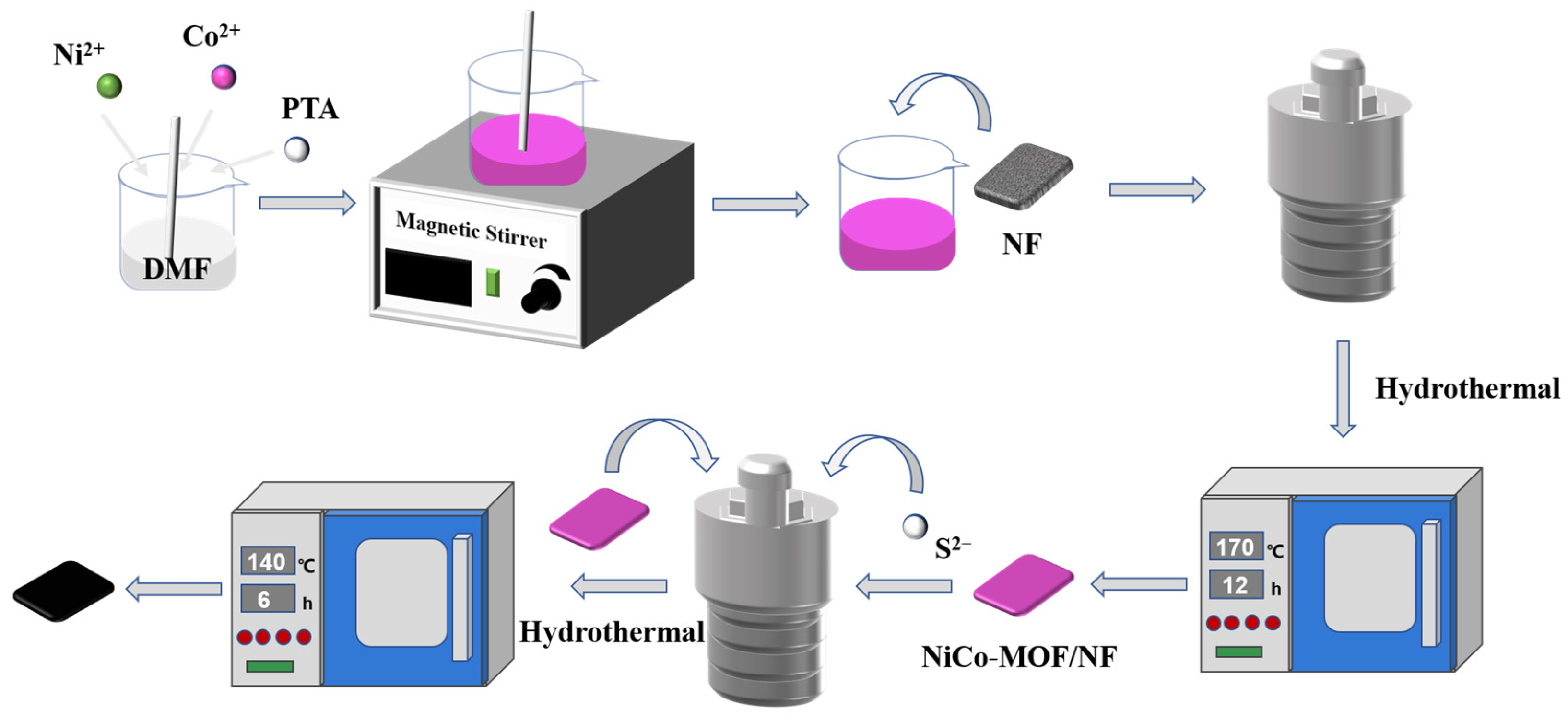
2.2. Synthesis of NiCo-S on NF (NiCo-S/NF)
2.3. Material Characterizations
2.4. Electrochemical Performance Tests
2.4.1. Three-Electrode System
2.4.2. Two-Electrode System
3. Results and Discussions
3.1. Structural and Morphology Characterization
3.2. Electrochemical Performances of NiCo-S/NF Electrode
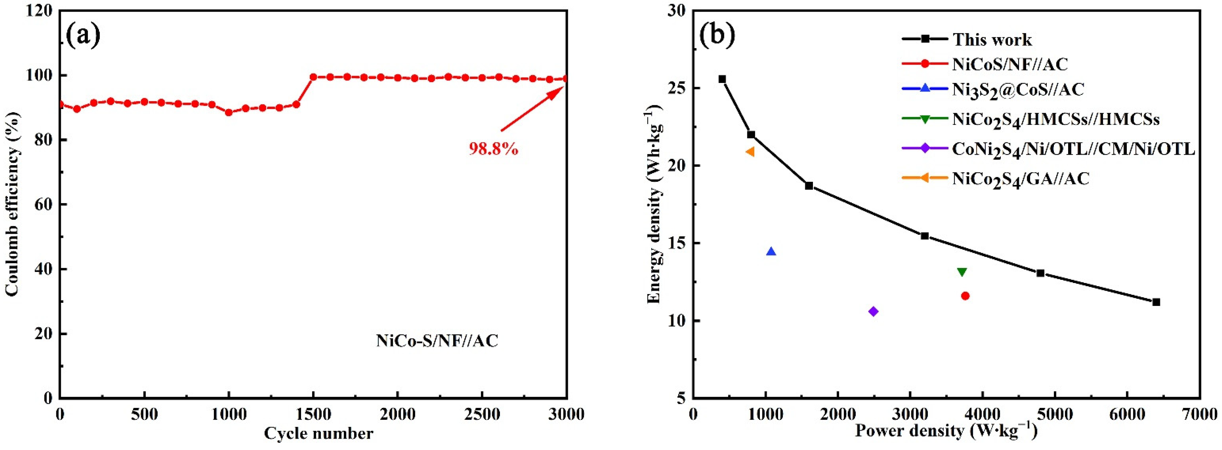
3.3. Electrochemical Measurements of NiCo-S//AC HSC Device
4. Conclusions
Author Contributions
Funding
Data Availability Statement
Conflicts of Interest
References
- Xiong, X.; Chen, J.; Zhang, D.; Li, A.; Zhang, J.; Zeng, X. Hetero-structured nanocomposites of Ni/Co/O/S for high-performance pseudo-supercapacitors. Electrochim. Acta 2019, 299, 298–311. [Google Scholar] [CrossRef]
- Arbi, H.M.; Yadav, A.A.; Anil Kumar, Y.; Moniruzzaman, M.; Alzahmi, S.; Obaidat, I.M. Polypyrrole-Assisted Ag Doping Strategy to Boost Co(OH)2 Nanosheets on Ni Foam as a Novel Electrode for High-Performance Hybrid Supercapacitors. Nanomaterials 2022, 12, 3982. [Google Scholar] [CrossRef] [PubMed]
- Rajesh, J.A.; Park, J.Y.; Manikandan, R.; Ahn, K.S. Rationally Designed Bimetallic Co-Ni Sulfide Microspheres as High-Performance Battery-Type Electrode for Hybrid Supercapacitors. Nanomaterials 2022, 12, 4435. [Google Scholar] [CrossRef] [PubMed]
- Lyu, L.; Hooch Antink, W.; Kim, Y.S.; Kim, C.W.; Hyeon, T.; Piao, Y. Recent Development of Flexible and Stretchable Supercapacitors Using Transition Metal Compounds as Electrode Materials. Small 2021, 17, 2101974. [Google Scholar] [CrossRef]
- Naskar, P.; Maiti, A.; Chakraborty, P.; Kundu, D.; Biswas, B.; Banerjee, A. Chemical supercapacitors: A review focusing on metallic compounds and conducting polymers. J. Mater. Chem. A 2020, 9, 1970–2017. [Google Scholar] [CrossRef]
- Wang, Z.; Hong, P.; Zhao, H.; Lei, Y. Recent Developments and Future Prospects of Transition Metal Compounds as Electrode Materials for Potassium-Ion Hybrid Capacitors. Adv. Mater. Technol. 2022, 8, 2200515. [Google Scholar] [CrossRef]
- Ramkumar, R.; Dhakal, G.; Shim, J.J.; Kim, W.K. NiO/Ni Nanowafer Aerogel Electrodes for High Performance Supercapacitors. Nanomaterials 2022, 12, 3813. [Google Scholar] [CrossRef]
- Liu, R.; Zhou, A.; Zhang, X.; Mu, J.; Che, H.; Wang, Y.; Wang, T.-T.; Zhang, Z.; Kou, Z. Fundamentals, advances and challenges of transition metal compounds-based supercapacitors. Chem. Eng. J. 2021, 412, 128611. [Google Scholar] [CrossRef]
- Huang, M.; Zhao, K.; He, D.; He, J.; Wang, Y. MOF-Derived Nickel–Cobalt Sulfide Nanoflakes Wrapped Carbon Nanotubes for Hybrid Supercapacitors. Energy Fuels 2022, 36, 15234–15243. [Google Scholar] [CrossRef]
- Chen, S.; Yang, Y.; Zhan, Z.; Xie, J.; Xiong, J. Designed construction of hierarchical NiCo2S4@polypyrrole core–shell nanosheet arrays as electrode materials for high-performance hybrid supercapacitors. RSC Adv. 2017, 7, 18447–18455. [Google Scholar] [CrossRef] [Green Version]
- Zhang, J.; Guan, H.; Liu, Y.; Zhao, Y.; Zhang, B. Hierarchical polypyrrole nanotubes@NiCo2S4 nanosheets core-shell composites with improved electrochemical performance as supercapacitors. Electrochim. Acta 2017, 258, 182–191. [Google Scholar] [CrossRef]
- Rao, S.S. Hierarchical nanospheres of NiCoS/NF for high-performance supercapacitors. Nano-Struct. Nano-Objects 2019, 19, 100366. [Google Scholar] [CrossRef]
- Zhao, J.; Hou, S.; Bai, Y.; Lian, Y.; Zhou, Q.; Ban, C.; Wang, Z.; Zhang, H. Multilayer dodecahedrons Zn-Co sulfide for supercapacitors. Electrochim. Acta 2020, 354, 136714. [Google Scholar] [CrossRef]
- Yu, S.; Xu, J.; Xiang, C.; Zou, Y.; Hu, Z.; Xu, F.; Sun, L. Bifunctional metal-organic framework-derived nitrogen-doped porous multishell CuCoS@NiCoS nanospheres for supercapacitors and hydrogen evolution reactions. J. Energy Storage 2022, 55, 105541. [Google Scholar] [CrossRef]
- Xu, X.; Liu, Q.; Liang, L.; Gu, H.; Zhao, Y.; Xing, X.; Zhang, X.; Hu, Y. Well-designed nanosheet-constructed porous CoMoS4 arrays for ultrahigh-performance supercapacitors. Ceram. Int. 2020, 46, 4878–4888. [Google Scholar] [CrossRef]
- Wu, Z.; Pu, X.; Ji, X.; Zhu, Y.; Jing, M.; Chen, Q.; Jiao, F. High Energy Density Asymmetric Supercapacitors From Mesoporous NiCo2S4 Nanosheets. Electrochim. Acta 2015, 174, 238–245. [Google Scholar] [CrossRef]
- Zheng, L.; Song, J.; Ye, X.; Wang, Y.; Shi, X.; Zheng, H. Construction of self-supported hierarchical NiCo-S nanosheet arrays for supercapacitors with ultrahigh specific capacitance. Nanoscale 2020, 12, 13811–13821. [Google Scholar] [CrossRef] [PubMed]
- Zhu, T.; Zhang, G.; Hu, T.; He, Z.; Lu, Y.; Wang, G.; Guo, H.; Luo, J.; Lin, C.; Chen, Y. Synthesis of NiCo2S4-based nanostructured electrodes supported on nickel foams with superior electrochemical performance. J. Mater. Sci. 2015, 51, 1903–1913. [Google Scholar] [CrossRef]
- Ma, L.; Hu, Y.; Chen, R.; Zhu, G.; Chen, T.; Lv, H.; Wang, Y.; Liang, J.; Liu, H.; Yan, C.; et al. Self-assembled ultrathin NiCo2S4 nanoflakes grown on Ni foam as high-performance flexible electrodes for hydrogen evolution reaction in alkaline solution. Nano Energy 2016, 24, 139–147. [Google Scholar] [CrossRef] [Green Version]
- Soram, B.S.; Thangjam, I.S.; Dai, J.Y.; Kshetri, T.; Kim, N.H.; Lee, J.H. Flexible transparent supercapacitor with core-shell Cu@Ni@NiCoS nanofibers network electrode. Chem. Eng. J. 2020, 395, 125019. [Google Scholar] [CrossRef]
- Chen, X.; Xie, R.; Li, H.; Jaber, F.; Musharavati, F.; Zalnezhad, E.; Bae, S.; Hui, K.S.; Hui, K.N. Supercapacitor performance of porous nickel cobaltite nanosheets. Sci. Rep. 2020, 10, 18956. [Google Scholar] [CrossRef] [PubMed]
- Wen, Y.; Peng, S.; Wang, Z.; Hao, J.; Qin, T.; Lu, S.; Zhang, J.; He, D.; Fan, X.; Cao, G. Facile synthesis of ultrathin NiCo2S4 nano-petals inspired by blooming buds for high-performance supercapacitors. J. Mater. Chem. A 2017, 5, 7144–7152. [Google Scholar] [CrossRef]
- Chen, X.J.; Chen, D.; Guo, X.Y.; Wang, R.M.; Zhang, H.Z. Facile Growth of Caterpillar-like NiCo2S4 Nanocrystal Arrays on Nickle Foam for High-Performance Supercapacitors. ACS Appl. Mater. Interfaces 2017, 9, 18774–18781. [Google Scholar] [CrossRef]
- Li, X.; Fu, Y.; Ma, H.; Liu, X.; Li, L.; Ma, J.; Liang, C.; Jin, M.; Hua, Y.; Wang, C. Preparation of a hollow cube NiCo2S4 and its application in supercapacitor. J. Chem. Sci. 2020, 132, 101. [Google Scholar] [CrossRef]
- Ma, L.; Xu, L.; Zhou, X.; Xu, X.; Zhang, L. Synthesis of a hierarchical MoSe2/C hybrid with enhanced electrochemical performance for supercapacitors. RSC Adv. 2016, 6, 91621–91628. [Google Scholar] [CrossRef]
- Wang, J.; Huang, Y.; Han, X.; Zhang, S.; Wang, M.; Yan, J.; Chen, C.; Zong, M. Construction of hierarchical Co9S8@NiO synergistic microstructure for high-performance asymmetric supercapacitor. J. Colloid Interface Sci. 2021, 603, 440–449. [Google Scholar] [CrossRef]
- Cao, W.; Liu, Y.; Xu, F.; Xia, Q.; Du, G.; Fan, Z.; Chen, N. Metal-organic framework derived carbon-coated spherical bimetallic nickel-cobalt sulfide nanoparticles for hybrid supercapacitors. Electrochim. Acta 2021, 385, 138433. [Google Scholar] [CrossRef]
- Yue, X.; Chen, Z.; Xiao, C.; Song, G.; Zhang, S.; He, H. Synthesis of CNT@CoS/NiCo Layered Double Hydroxides with Hollow Nanocages to Enhance Supercapacitors Performance. Nanomaterials 2022, 12, 3509. [Google Scholar] [CrossRef]
- Liu, T.; Liu, J.; Zhang, L.; Cheng, B.; Yu, J. Construction of nickel cobalt sulfide nanosheet arrays on carbon cloth for performance-enhanced supercapacitor. J. Mater. Sci. Technol. 2020, 47, 113–121. [Google Scholar] [CrossRef]
- Xiancai, P.; Xiaolei, G.; Xu, L.; Jianhua, Y.; Qian, Z.; Lina, S.; Lifeng, D. Synthesis and Supercapacitive Properties of Ni/Co-S Derived from MOF-74. ECS Trans. 2020, 98, 29. [Google Scholar] [CrossRef]
- Zhao, J.; Li, Z.; Zhang, M.; Meng, A.; Li, Q. Vertically cross-linked and porous CoNi2S4 nanosheets-decorated SiC nanowires with exceptional capacitive performance as a free-standing electrode for asymmetric supercapacitors. J. Power Source 2016, 332, 355–365. [Google Scholar] [CrossRef]
- He, X.; Liu, Q.; Liu, J.; Li, R.; Zhang, H.; Chen, R.; Wang, J. High-performance all-solid-state asymmetrical supercapacitors based on petal-like NiCo2S4/Polyaniline nanosheets. Chem. Eng. J. 2017, 325, 134–143. [Google Scholar] [CrossRef]
- Zou, R.; Yuen, M.F.; Yu, L.; Hu, J.; Lee, C.-S.; Zhang, W. Electrochemical Energy Storage Application and Degradation Analysis of Carbon-Coated Hierarchical NiCo2S4 Core-Shell Nanowire Arrays Grown Directly on Graphene/Nickel Foam. Sci. Rep. 2016, 6, 20264. [Google Scholar] [CrossRef] [Green Version]
- Yi, T.-F.; Chang, H.; Wei, T.-T.; Qi, S.-Y.; Li, Y.; Zhu, Y.-R. Approaching high-performance electrode materials of ZnCo2S4 nanoparticle wrapped carbon nanotubes for supercapacitors. J. Mater. 2021, 7, 563–576. [Google Scholar] [CrossRef]
- Han, D.; Wei, J.; Zhao, Y.; Shen, Y.; Pan, Y.; Wei, Y.; Mao, L. Metal–organic framework derived petal-like Co3O4@CoNi2S4 hybrid on carbon cloth with enhanced performance for supercapacitors. Inorg. Chem. Front. 2020, 7, 1428–1436. [Google Scholar] [CrossRef]
- Hong, J.; Park, S.-J.; Kim, S. Synthesis and electrochemical characterization of nanostructured Ni-Co-MOF/graphene oxide composites as capacitor electrodes. Electrochim. Acta 2019, 311, 62–71. [Google Scholar] [CrossRef]
- Dai, W.; Ren, K.; Zhu, Y.-a.; Pan, Y.; Yu, J.; Lu, T. Flower-like CoNi2S4/Ni3S2 nanosheet clusters on nickel foam as bifunctional electrocatalyst for overall water splitting. J. Alloys Compd. 2020, 844, 156252. [Google Scholar] [CrossRef]
- Zhang, Y.; Wang, X.; Shen, M.; Fu, X.; Huang, M.; Liu, X.; Zhang, Y.X. Uniform growth of NiCo2S4 nanoflakes arrays on nickel foam for binder-free high-performance supercapacitors. J. Mater. Sci. 2018, 54, 4821–4830. [Google Scholar] [CrossRef]
- Zhu, J.; Han, C.; Song, X. Facile synthesis of novel CoNi2S4/carbon nanofibers composite for high-performance supercapacitor. Mater. Chem. Phys. 2022, 283, 126038. [Google Scholar] [CrossRef]
- Wang, B.; Li, W.; Liu, Z.; Duan, Y.; Zhao, B.; Wang, Y.; Liu, J. Incorporating Ni-MOF structure with polypyrrole: Enhanced capacitive behavior as electrode material for supercapacitor. RSC Adv. 2020, 10, 12129–12134. [Google Scholar] [CrossRef] [Green Version]
- Xinbo, P.; Lijun, Z.; Hongbin, L.; Manying, G.; Chengdong, H.; Wenquan, W. Hierarchical structure Ni3S2/Ni(OH)2 nanoarrays towards high-performance supercapacitors. J. Solid State Chem. 2022, 309, 122974. [Google Scholar] [CrossRef]
- Yang, P.; Feng, L.; Wang, S.; Shi, J.; Xing, H. Construction of core-shell Ni@Ni3S2@NiCo2O4 nanoflakes as advanced electrodes for high-performance hybrid supercapacitors. J. Phys. Chem. Solids 2021, 155, 110110. [Google Scholar] [CrossRef]
- Ansarinejad, H.; Shabani-Nooshabadi, M.; Ghoreishi, S.M. Enhanced Supercapacitor Performance Using a Co3O4@Co3S4 Nanocomposite on Reduced Graphene Oxide/Ni Foam Electrodes. Chem. Asian J. 2021, 16, 1258–1270. [Google Scholar] [CrossRef]
- Huang, C.; Gao, A.; Zhu, Z.; Yi, F.; Wang, M.; Hao, J.; Cheng, H.; Ling, J.; Shu, D. Metal organic frameworks derived Ni-doped hierarchical NiXCo1-XS@C bundled-like nanostructures for enhanced supercapacitors. Electrochim. Acta 2022, 406, 139872. [Google Scholar] [CrossRef]
- Chen, Y.; Jing, C.; Fu, X.; Shen, M.; Li, K.; Liu, X.; Yao, H.-C.; Zhang, Y.; Yao, K.X. Synthesis of porous NiCoS nanosheets with Al leaching on ordered mesoporous carbon for high-performance supercapacitors. Chem. Eng. J. 2020, 384, 123367. [Google Scholar] [CrossRef]
- Chen, H.; Jiang, J.; Zhang, L.; Wan, H.; Qi, T.; Xia, D. Highly conductive NiCo2S4 urchin-like nanostructures for high-rate pseudocapacitors. Nanoscale 2013, 5, 8879–8883. [Google Scholar] [CrossRef]
- Yang, Y.; Zhang, Y.; Zhu, C.; Xie, Y.; Lv, L.; Chen, W.; He, Y.; Hu, Z. Synthesis of ultrafine CoNi2S4 nanowire on carbon cloth as an efficient positive electrode material for high-performance hybrid supercapacitors. J. Alloys Compd. 2020, 823, 153885. [Google Scholar] [CrossRef]
- Huang, Z.; Zhang, M.; Wang, A.; Liu, H.; Wang, Z.; Huang, C.; Yue, S.; Xie, J.; Hu, Z. Bimetallic organic framework in situ fabrication nanoflower-like cobalt nickel sulfide and ultrathin layered double hydroxide arrays for high-efficient asymmetric hybrid supercapacitor. J. Alloys Compd. 2023, 938, 168565. [Google Scholar] [CrossRef]
- Wang, X.; Hu, J.; Su, Y.; Hao, J.; Liu, F.; Han, S.; An, J.; Lian, J. Ni Foam-Ni3S2@Ni(OH)2-Graphene Sandwich Structure Electrode Materials: Facile Synthesis and High Supercapacitor Performance. Chemistry 2017, 23, 4128–4136. [Google Scholar] [CrossRef] [PubMed]
- Hussain, S.; Hassan, M.; Javed, M.S.; Shaheen, A.; Ahmad Shah, S.S.; Nazir, M.T.; Najam, T.; Khan, A.J.; Zhang, X.; Liu, G. Distinctive flower-like CoNi2S4 nanoneedle arrays (CNS–NAs) for superior supercapacitor electrode performances. Ceram. Int. 2020, 46, 25942–25948. [Google Scholar] [CrossRef]
- Liu, Y.; Ma, Z.; Niu, H.; Yang, Q.; Jia, H.; Shi, W. MOF-derived Co9S8 polyhedrons on NiCo2S4 nanowires for high-performance hybrid supercapacitors. Inorg. Chem. Front. 2020, 7, 4092–4100. [Google Scholar] [CrossRef]
- Jiongliang, Y.; Wei, Z. Fabrication of NiCo2S4/Nickel Foam Composite Electrodes by Cyclic Voltammetric Deposition and Their Supercapacitor Performance. Mater. Lett. 2022, 330, 133338. [Google Scholar] [CrossRef]
- Yu, J.; Pang, X.; Yin, Q.; Chen, D.; Dong, H.; Zhang, Q.; Sui, J.; Sui, L.; Dong, L. Metal-organic frameworks supported Ni–Co–S nanosheet arrays for advanced hybrid supercapacitors. Int. J. Hydrogen Energy 2022, 47, 39265–39275. [Google Scholar] [CrossRef]
- Huang, X.; Gou, L. High performance asymmetric supercapacitor based on hierarchical flower-like NiCo2S4@polyaniline. Appl. Surf. Sci. 2019, 487, 68–76. [Google Scholar] [CrossRef]
- Xiong, D.; Gu, M.; Chen, C.; Lu, C.; Yi, F.-Y.; Ma, X. Rational design of bimetallic metal–organic framework composites and their derived sulfides with superior electrochemical performance to remarkably boost oxygen evolution and supercapacitors. Chem. Eng. J. 2021, 404, 127111. [Google Scholar] [CrossRef]
- Li, R.; Wang, S.; Wang, J.; Huang, Z. Ni3S2@CoS core-shell nano-triangular pyramid arrays on Ni foam for high-performance supercapacitors. Phys. Chem. Chem. Phys. 2015, 17, 16434–16442. [Google Scholar] [CrossRef]
- Liu, Y.; Jiang, G.; Huang, Z.; Lu, Q.; Yu, B.; Evariste, U.; Ma, P. Decoration of Hollow Mesoporous Carbon Spheres by NiCo2S4 Nanoparticles as Electrode Materials for Asymmetric Supercapacitors. ACS Appl. Energy Mater. 2019, 2, 8079–8089. [Google Scholar] [CrossRef]
- Song, J.; Chen, Y.; Cao, K.; Lu, Y.; Xin, J.H.; Tao, X. Fully Controllable Design and Fabrication of Three-Dimensional Lattice Supercapacitors. ACS Appl. Mater. Interfaces 2018, 10, 39839–39850. [Google Scholar] [CrossRef] [PubMed]
- Li, B.; Tian, Z.; Li, H.; Yang, Z.; Wang, Y.; Wang, X. Self-supporting graphene aerogel electrode intensified by NiCo2S4 nanoparticles for asymmetric supercapacitor. Electrochim. Acta 2019, 314, 32–39. [Google Scholar] [CrossRef]


| Electrode | Morphology | Electrolyte | Performance | Refs. |
|---|---|---|---|---|
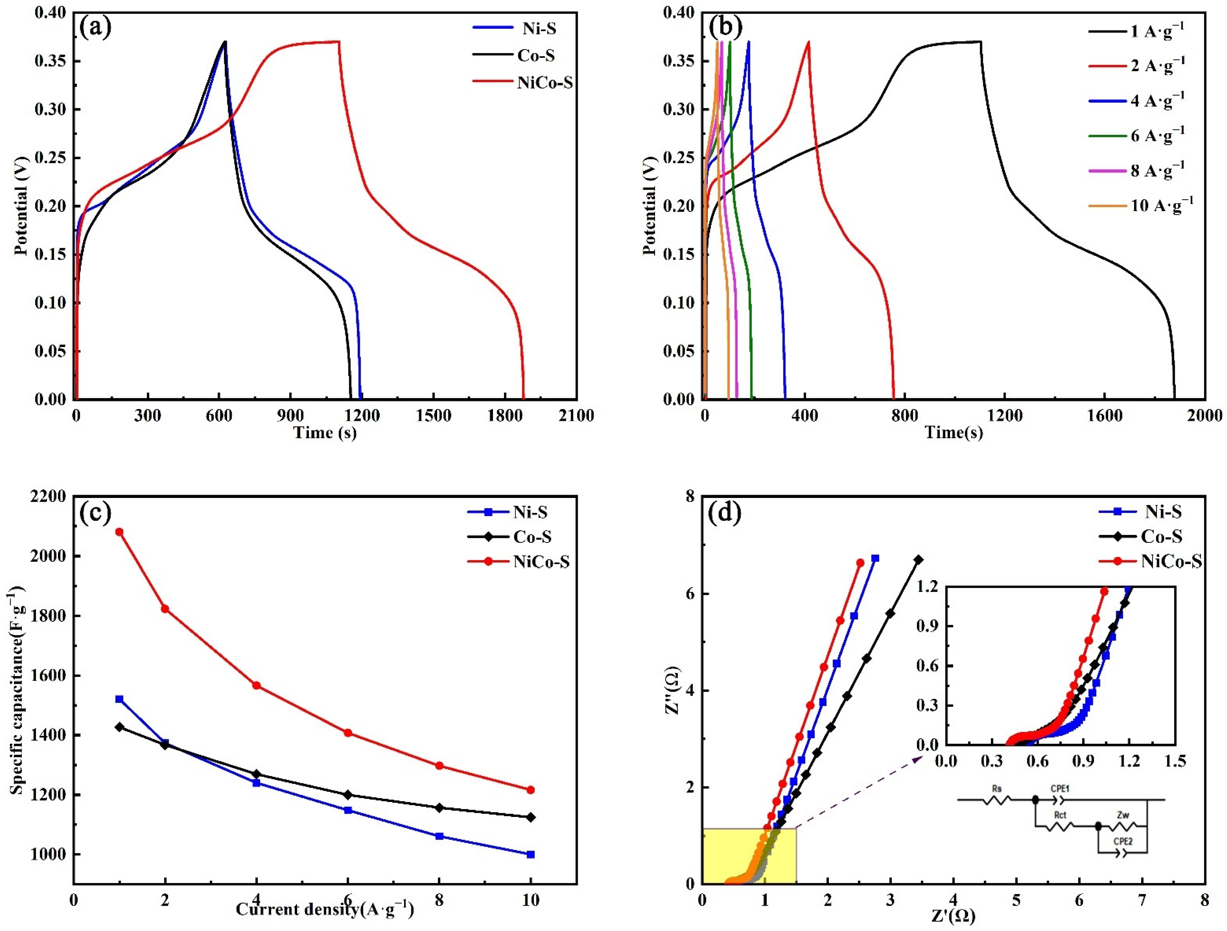
| NiCo-S/NF | Nanosheet@nanoleaves | 6 M KOH | 2081 F∙g−1 1 A∙g−1 | This work |
| NiCo2S4 | Nanoflowers | 6 M KOH | 1757 F∙g−1 1 A∙g−1 | [45] |
| NiCo2S4 | Urchin-like | 6 M KOH | 1149 F∙g−1 1 A∙g−1 | [46] |
| CoNi2S4@CC | Nanowire | 6 M KOH | 1872 F∙g−1 1 A∙g−1 | [47] |
| NiCo2S4@NC | Nanoflower-like | 6 M KOH | 1021.6 F∙g−1 1 A∙g−1 | [48] |
| Samples | NiCo-S/NF | Ni-S/NF | Co-S/NF |
|---|---|---|---|
| Rs | 0.41 | 0.53 | 0.44 |
| Rct | 0.13 | 0.14 | 0.27 |
| Wo | 0.53 | 0.60 | 0.83 |
Disclaimer/Publisher’s Note: The statements, opinions and data contained in all publications are solely those of the individual author(s) and contributor(s) and not of MDPI and/or the editor(s). MDPI and/or the editor(s) disclaim responsibility for any injury to people or property resulting from any ideas, methods, instructions or products referred to in the content. |
© 2023 by the authors. Licensee MDPI, Basel, Switzerland. This article is an open access article distributed under the terms and conditions of the Creative Commons Attribution (CC BY) license (https://creativecommons.org/licenses/by/4.0/).
Share and Cite
Li, J.; Li, J.; Shao, M.; Yan, Y.; Li, R. MOF-Derived Ultrathin NiCo-S Nanosheet Hybrid Array Electrodes Prepared on Nickel Foam for High-Performance Supercapacitors. Nanomaterials 2023, 13, 1229. https://doi.org/10.3390/nano13071229
Li J, Li J, Shao M, Yan Y, Li R. MOF-Derived Ultrathin NiCo-S Nanosheet Hybrid Array Electrodes Prepared on Nickel Foam for High-Performance Supercapacitors. Nanomaterials. 2023; 13(7):1229. https://doi.org/10.3390/nano13071229
Chicago/Turabian StyleLi, Jing, Jun Li, Meng Shao, Yanan Yan, and Ruoliu Li. 2023. "MOF-Derived Ultrathin NiCo-S Nanosheet Hybrid Array Electrodes Prepared on Nickel Foam for High-Performance Supercapacitors" Nanomaterials 13, no. 7: 1229. https://doi.org/10.3390/nano13071229