
Antibiotic Degradation via Fenton Process Assisted by a 3-Electron Oxygen Reduction Reaction Pathway Catalyzed by Bio-Carbon–Manganese Composites
 ,
,  , , ,
, , ,  and
and 
Abstract
:1. Introduction
2. Experimental
2.1. Bio-Carbon–Manganese Composites Preparation
2.2. Textural and Chemical Characterization
2.3. Electrochemical Characterization
2.4. Electro-Fenton Processes
3. Results and Discussions
3.1. Morphological and Textural Characterization
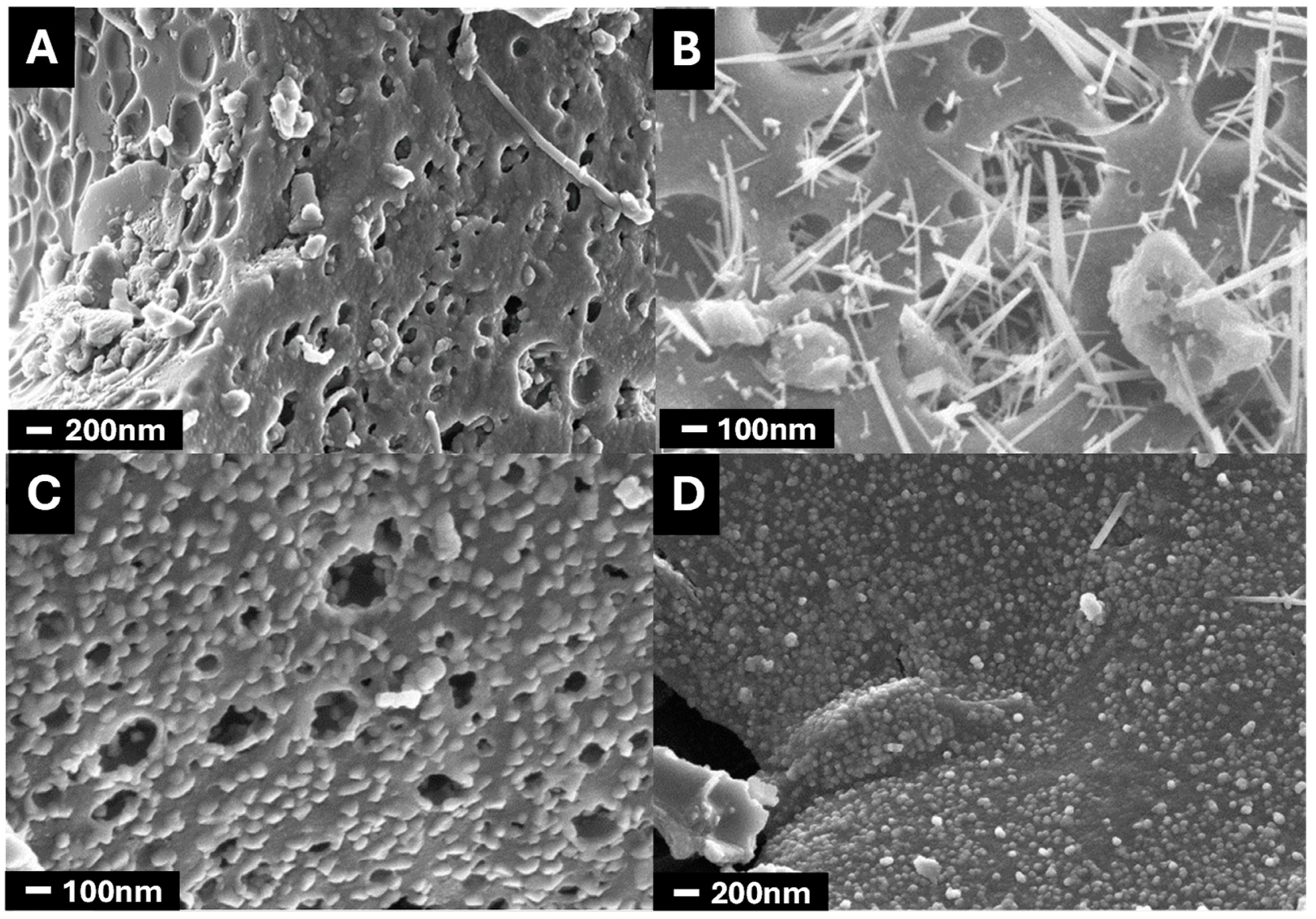
3.1.1. Morphology
3.1.2. The Porosity and Surface Area of the Composites
3.2. TGA
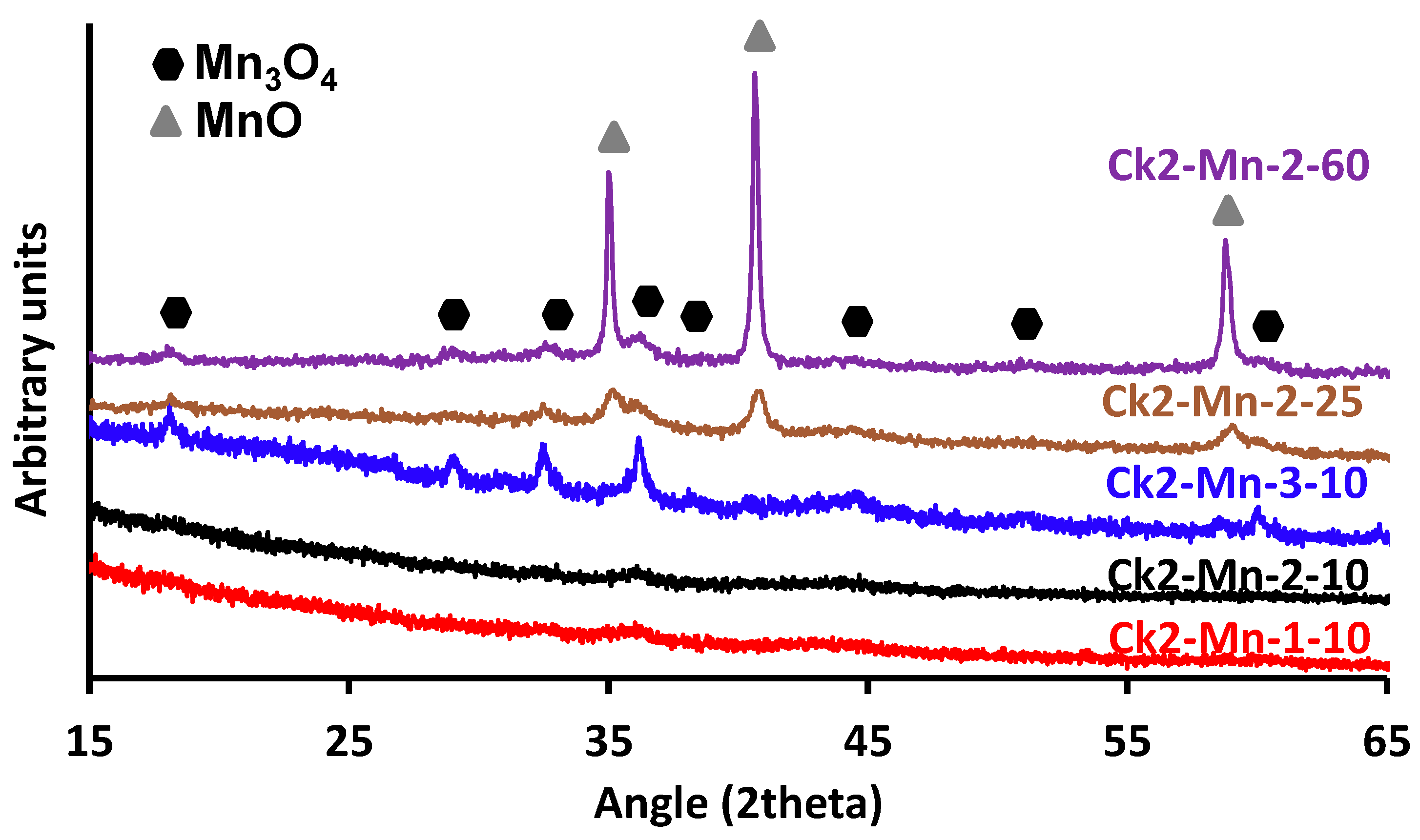
3.3. X-ray Diffraction
4. Surface Chemistry of Composites
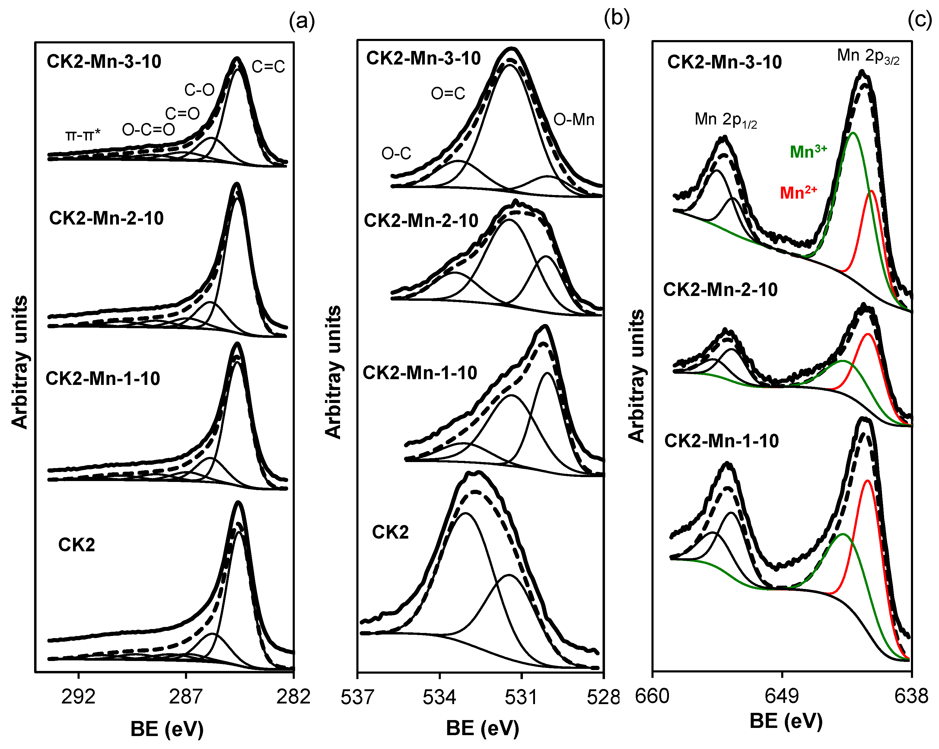
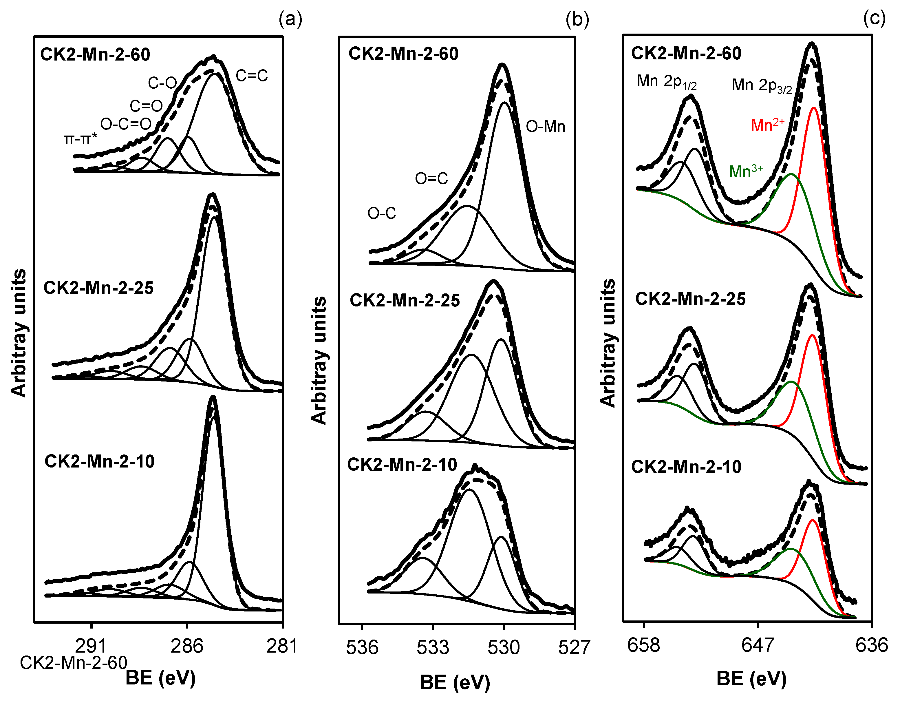
4.1. XPS Spectra
4.2. Electrochemical Characterization
4.3. Electro Fenton
5. Conclusions
Supplementary Materials
Author Contributions
Funding
Data Availability Statement
Acknowledgments
Conflicts of Interest
References
- Garza-Campos, B.; Morales-Acosta, D.; Hernández-Ramírez, A.; Guzmán-Mar, J.L.; Hinojosa-Reyes, L.; Manríquez, J.; Ruiz-Ruiz, E.J. Air Diffusion Electrodes Based on Synthetized Mesoporous Carbon for Application in Amoxicillin Degradation by Electro-Fenton and Solar Photo Electro-Fenton. Electrochim. Acta 2018, 269, 232–240. [Google Scholar] [CrossRef]
- Ahmadi, A.; Zarei, M.; Hassani, A.; Ebratkhahan, M.; Olad, A. Facile Synthesis of Iron(II) Doped Carbonaceous Aerogel as a Three-Dimensional Cathode and Its Excellent Performance in Electro-Fenton Degradation of Ceftazidime from Water Solution. Sep. Purif. Technol. 2021, 278, 119559. [Google Scholar] [CrossRef]
- Pan, Y.; Zhang, Y.; Zhou, M.; Cai, J.; Tian, Y. Enhanced Removal of Antibiotics from Secondary Wastewater Effluents by Novel UV/Pre-Magnetized Fe0/H2O2 Process. Water Res. 2019, 153, 144–159. [Google Scholar] [CrossRef] [PubMed]
- Qin, J.; Ruan, Y.; Yi, L.; Sun, H.; Qi, Q.; Zhao, L.; Xiong, Y.; Wang, J.; Fang, D. Tetracycline (TC) Degradation via Hydrodynamic Cavitation (HC) Combined Fenton’s Reagent: Optimizing Geometric and Operation Parameters. Chem. Eng. Process.-Process Intensif. 2022, 172, 108801. [Google Scholar] [CrossRef]
- Du, X.; Fu, W.; Su, P.; Zhang, Q.; Zhou, M. FeMo@porous Carbon Derived from MIL-53(Fe)@MoO3 as Excellent Heterogeneous Electro-Fenton Catalyst: Co-Catalysis of Mo. J. Environ. Sci. (China) 2023, 127, 652–666. [Google Scholar] [CrossRef] [PubMed]
- Yang, C.; Fan, Y.; Shang, S.; Li, P.; Li, X. yan Fabrication of a Permeable SnO2-Sb Reactive Anodic Filter for High-Efficiency Electrochemical Oxidation of Antibiotics in Wastewater. Environ. Int. 2021, 157. [Google Scholar] [CrossRef] [PubMed]
- Akbari, M.Z.; Xu, Y.; Lu, Z.; Peng, L. Review of Antibiotics Treatment by Advance Oxidation Processes. Environ. Adv. 2021, 5, 100111. [Google Scholar] [CrossRef]
- Yuan, Q.; Qu, S.; Li, R.; Huo, Z.Y.; Gao, Y.; Luo, Y. Degradation of Antibiotics by Electrochemical Advanced Oxidation Processes (EAOPs): Performance, Mechanisms, and Perspectives. Sci. Total Environ. 2023, 856, 159092. [Google Scholar] [CrossRef] [PubMed]
- Wang, J.; Zhuan, R. Degradation of Antibiotics by Advanced Oxidation Processes: An Overview. Sci. Total Environ. 2020, 701, 135023. [Google Scholar] [CrossRef]
- Midassi, S.; Bedoui, A.; Bensalah, N. Efficient Degradation of Chloroquine Drug by Electro-Fenton Oxidation: Effects of Operating Conditions and Degradation Mechanism. Chemosphere 2020, 260, 127558. [Google Scholar] [CrossRef]
- Cao, P.; Zhao, K.; Quan, X.; Chen, S.; Yu, H. Efficient and Stable Heterogeneous Electro-Fenton System Using Iron Oxides Embedded in Cu, N Co-Doped Hollow Porous Carbon as Functional Electrocatalyst. Sep. Purif. Technol. 2020, 238, 116424. [Google Scholar] [CrossRef]
- Le, T.T.; Hoang, V.C.; Zhang, W.; Kim, J.M.; Kim, J.; Moon, G.H.; Kim, S.H. Mesoporous Sulfur-Modified Metal Oxide Cathodes for Efficient Electro-Fenton Systems. Chem. Eng. J. Adv. 2022, 12, 100371. [Google Scholar] [CrossRef]
- Puga, A.; Rosales, E.; Pazos, M.; Sanromán, M.A. Prompt Removal of Antibiotic by Adsorption/Electro-Fenton Degradation Using an Iron-Doped Perlite as Heterogeneous Catalyst. Process Saf. Environ. Prot. 2020, 144, 100–110. [Google Scholar] [CrossRef]
- Arellano, M.; Oturan, N.; Oturan, M.A.; Pazos, M.; Sanromán, M.Á.; González-Romero, E. Differential Pulse Voltammetry as a Powerful Tool to Monitor the Electro-Fenton Process. Electrochim. Acta 2020, 354. [Google Scholar] [CrossRef]
- Ganzenko, O.; Trellu, C.; Oturan, N.; Huguenot, D.; Péchaud, Y.; van Hullebusch, E.D.; Oturan, M.A. Electro-Fenton Treatment of a Complex Pharmaceutical Mixture: Mineralization Efficiency and Biodegradability Enhancement. Chemosphere 2020, 253. [Google Scholar] [CrossRef] [PubMed]
- Chai, Y.; Qin, P.; Zhang, J.; Li, T.; Dai, Z.; Wu, Z. Simultaneous Removal of Fe(II) and Mn(II) from Acid Mine Wastewater by Electro-Fenton Process. Process Saf. Environ. Prot. 2020, 143, 76–90. [Google Scholar] [CrossRef]
- Deng, F.; Olvera-Vargas, H.; Zhou, M.; Qiu, S.; Sirés, I.; Brillas, E. Critical Review on the Mechanisms of Fe2+ Regeneration in the Electro-Fenton Process: Fundamentals and Boosting Strategies. Chem. Rev. 2023, 123, 4635–4662. [Google Scholar] [CrossRef] [PubMed]
- Wang, J.; Qin, J.; Liu, B.; Song, S. Reaction Mechanisms and Toxicity Evolution of Sulfamethoxazole Degradation by CoFe-N Doped C as Electro-Fenton Cathode. Sep. Purif. Technol. 2022, 298, 121655. [Google Scholar] [CrossRef]
- Verdaguer-Casadevall, A.; Deiana, D.; Karamad, M.; Siahrostami, S.; Malacrida, P.; Hansen, T.W.; Rossmeisl, J.; Chorkendorff, I.; Stephens, I.E.L. Trends in the Electrochemical Synthesis of H2O2: Enhancing Activity and Selectivity by Electrocatalytic Site Engineering. Nano Lett. 2014, 14, 1603–1608. [Google Scholar] [CrossRef]
- He, D.; Zhong, L.; Gan, S.; Xie, J.; Wang, W.; Liu, Z.; Guo, W.; Yang, X.; Niu, L. Hydrogen Peroxide Electrosynthesis via Regulating the Oxygen Reduction Reaction Pathway on Pt Noble Metal with Ion Poisoning. Electrochim. Acta 2021, 371, 137721. [Google Scholar] [CrossRef]
- Choe, Y.J.; Kim, J.; Byun, J.Y.; Kim, S.H. An Electro-Fenton System with Magnetite Coated Stainless Steel Mesh as Cathode. Catal. Today 2021, 359, 16–22. [Google Scholar] [CrossRef]
- Gholizadeh, A.M.; Zarei, M.; Ebratkhahan, M.; Hasanzadeh, A. Phenazopyridine Degradation by Electro-Fenton Process with Magnetite Nanoparticles-Activated Carbon Cathode, Artificial Neural Networks Modeling. J. Environ. Chem. Eng. 2021, 9, 104999. [Google Scholar] [CrossRef]
- Zarei, M.; Beheshti Nahand, F.; Khataee, A.; Hasanzadeh, A. Removal of Nalidixic Acid from Aqueous Solutions Using a Cathode Containing Three-Dimensional Graphene. J. Water Process Eng. 2019, 32, 100978. [Google Scholar] [CrossRef]
- Scialdone, O.; Galia, A.; Sabatino, S. Electro-Generation of H2O2 and Abatement of Organic Pollutant in Water by an Electro-Fenton Process in a Microfluidic Reactor. Electrochem. Commun. 2013, 26, 45–47. [Google Scholar] [CrossRef]
- Nair, K.M.; Kumaravel, V.; Pillai, S.C. Carbonaceous Cathode Materials for Electro-Fenton Technology: Mechanism, Kinetics, Recent Advances, Opportunities and Challenges. Chemosphere 2021, 269, 129325. [Google Scholar] [CrossRef] [PubMed]
- Ahmad, A.; Priyadarshini, M.; Yadav, S. The Potential of Biochar-Based Catalysts in Removal of Persistent Organic Pollutants from Wastewater: A Review. Chem. Eng. Res. Des. 2022, 187, 470–496. [Google Scholar] [CrossRef]
- Xin, S.; Huo, S.; Zhang, C.; Ma, X.; Liu, W.; Xin, Y.; Gao, M. Coupling Nitrogen/Oxygen Self-Doped Biomass Porous Carbon Cathode Catalyst with CuFeO2/Biochar Particle Catalyst for the Heterogeneous Visible-Light Driven Photo-Electro-Fenton Degradation of Tetracycline. Appl. Catal. B 2022, 305, 121024. [Google Scholar] [CrossRef]
- Zhou, W.; Li, F.; Su, Y.; Li, J.; Chen, S.; Xie, L.; Wei, S.; Meng, X.; Rajic, L.; Gao, J.; et al. O-Doped Graphitic Granular Biochar Enables Pollutants Removal via Simultaneous H2O2 Generation and Activation in Neutral Fe-Free Electro-Fenton Process. Sep. Purif. Technol. 2021, 262, 118327. [Google Scholar] [CrossRef]
- Hu, X.; Deng, Y.; Zhou, J.; Liu, B.; Yang, A.; Jin, T.; Fai Tsang, Y. N- and O Self-Doped Biomass Porous Carbon Cathode in an Electro-Fenton System for Chloramphenicol Degradation. Sep. Purif. Technol. 2020, 251, 117376. [Google Scholar] [CrossRef]
- Gao, M.; Wang, W.K.; Zheng, Y.M.; Zhao, Q.B.; Yu, H.Q. Hierarchically Porous Biochar for Supercapacitor and Electrochemical H2O2 Production. Chem. Eng. J. 2020, 402, 126171. [Google Scholar] [CrossRef]
- Deng, F.; Olvera-Vargas, H.; Garcia-Rodriguez, O.; Zhu, Y.; Jiang, J.; Qiu, S.; Yang, J. Waste-Wood-Derived Biochar Cathode and Its Application in Electro-Fenton for Sulfathiazole Treatment at Alkaline PH with Pyrophosphate Electrolyte. J. Hazard. Mater. 2019, 377, 249–258. [Google Scholar] [CrossRef] [PubMed]
- Liang, J.; Tang, D.; Huang, L.; Chen, Y.; Ren, W.; Sun, J. High Oxygen Reduction Reaction Performance Nitrogen-Doped Biochar Cathode: A Strategy for Comprehensive Utilizing Nitrogen and Carbon in Water Hyacinth. Bioresour. Technol. 2018, 267, 524–531. [Google Scholar] [CrossRef] [PubMed]
- Sun, C.; Chen, T.; Huang, Q.; Duan, X.; Zhan, M.; Ji, L.; Li, X.; Wang, S.; Yan, J. Biochar Cathode: Reinforcing Electro-Fenton Pathway against Four-Electron Reduction by Controlled Carbonization and Surface Chemistry. Sci. Total Environ. 2021, 754, 142136. [Google Scholar] [CrossRef] [PubMed]
- Gopinath, A.; Divyapriya, G.; Srivastava, V.; Laiju, A.R.; Nidheesh, P.V.; Kumar, M.S. Conversion of Sewage Sludge into Biochar: A Potential Resource in Water and Wastewater Treatment. Environ. Res. 2021, 194, 110656. [Google Scholar] [CrossRef]
- Dessalle, A.; Quílez-Bermejo, J.; Fierro, V.; Xu, F.; Celzard, A. Recent Progress in the Development of Efficient Biomass-Based ORR Electrocatalysts. Carbon N. Y. 2023, 203, 237–260. [Google Scholar] [CrossRef]
- Quílez-Bermejo, J.; Morallón, E.; Cazorla-Amorós, D. On the Deactivation of N-Doped Carbon Materials Active Sites during Oxygen Reduction Reaction. Carbon N. Y. 2022, 189, 548–560. [Google Scholar] [CrossRef]
- Zhang, T.; Wang, H.; Zhang, J.; Ma, J.; Wang, Z.; Liu, J.; Gong, X. Carbon Charge Population and Oxygen Molecular Transport Regulated by Program-Doping for Highly Efficient 4e-ORR. Chem. Eng. J. 2022, 444, 136560. [Google Scholar] [CrossRef]
- Abdelwahab, A.; Castelo-Quibén, J.; Vivo-Vilches, J.F.; Pérez-Cadenas, M.; Maldonado-Hódar, F.J.; Carrasco-Marín, F.; Pérez-Cadenas, A.F. Electrodes Based on Carbon Aerogels Partially Graphitized by Doping with Transition Metals for Oxygen Reduction Reaction. Nanomaterials 2018, 8, 266. [Google Scholar] [CrossRef]
- Fajardo-Puerto, E.; Elmouwahidi, A.; Bailón-García, E.; Pérez-Cadenas, A.F.; Carrasco-Marín, F. From Fenton and ORR 2e−-Type Catalysts to Bifunctional Electrodes for Environmental Remediation Using the Electro-Fenton Process. Catalysts 2023, 13, 674. [Google Scholar] [CrossRef]
- Xu, X.; Pan, Y.; Ge, L.; Chen, Y.; Mao, X.; Guan, D.; Li, M.; Zhong, Y.; Hu, Z.; Peterson, V.K.; et al. High-Performance Perovskite Composite Electrocatalysts Enabled by Controllable Interface Engineering. Small 2021, 17, 2101573. [Google Scholar] [CrossRef]
- Li, Y.; Wang, C.; Pan, S.; Zhao, X.; Liu, N. Mn Doping Improves In-Situ H2O2 Generation and Activation in Electro-Fenton Process by Fe/Mn@CC Cathode Using High-Temperature Shock Technique. Chemosphere 2022, 307, 136074. [Google Scholar] [CrossRef] [PubMed]
- Abbas, Z.I.; Abbas, A.S. Oxidative Degradation of Phenolic Wastewater by Electro-Fenton Process Using MnO2-Graphite Electrode. J. Environ. Chem. Eng. 2019, 7, 103108. [Google Scholar] [CrossRef]
- Li, D.; Sun, T.; Wang, L.; Wang, N. Enhanced Electro-Catalytic Generation of Hydrogen Peroxide and Hydroxyl Radical for Degradation of Phenol Wastewater Using MnO2/Nano-G|Foam-Ni/Pd Composite Cathode. Electrochim. Acta 2018, 282, 416–426. [Google Scholar] [CrossRef]
- Rubio, J.A.; Fdez-Güelfo, L.A.; Romero-García, L.I.; Wilkie, A.C.; García-Morales, J.L. Co-Digestion of Two-Phase Olive-Mill Waste and Cattle Manure: Influence of Solids Content on Process Performance. Fuel 2022, 322, 124187. [Google Scholar] [CrossRef]
- Elmouwahidi, A.; Bailón-garcía, E.; Pérez-cadenas, A.F.; Maldonado-hódar, F.J.; Carrasco-marín, F. Activated Carbons from KOH and H3PO4 Activation of Olive Residues and Its Application as Supercapacitor Electrodes. Electrochim. Acta 2017, 229, 219–228. [Google Scholar] [CrossRef]
- Walton, K.S.; Snurr, R.Q. Applicability of the BET Method for Determining Surface Areas of Microporous Metal-Organic Frameworks. J. Am. Chem. Soc. 2007, 129, 8552–8556. [Google Scholar] [CrossRef]
- Raja, P.M.V.; Barron, A.R. 2.3: BET Surface Area Analysis of Nanoparticles; 2019; Vol. i. Available online: https://chem.libretexts.org/Bookshelves/Analytical_Chemistry/Physical_Methods_in_Chemistry_and_Nano_Science_(Barron)/02%3A_Physical_and_Thermal_Analysis/2.03%3A_BET_Surface_Area_Analysis_of_Nanoparticles (accessed on 10 May 2024).
- Nguyen, C.; Do, D.D. The Dubinin-Radushkevich Equation and the Underlying Microscopic Adsorption Description. Carbon N. Y. 2001, 39, 1327–1336. [Google Scholar] [CrossRef]
- Zhou, R.; Zheng, Y.; Jaroniec, M.; Qiao, S.Z. Determination of the Electron Transfer Number for the Oxygen Reduction Reaction: From Theory to Experiment. ACS Catal. 2016, 6, 4720–4728. [Google Scholar] [CrossRef]
- Jiang, K.; Back, S.; Akey, A.J.; Xia, C.; Hu, Y.; Liang, W.; Schaak, D.; Stavitski, E.; Nørskov, J.K.; Siahrostami, S.; et al. Highly Selective Oxygen Reduction to Hydrogen Peroxide on Transition Metal Single Atom Coordination. Nat. Commun. 2019, 10. [Google Scholar] [CrossRef]
- Xu, S.; Kim, Y.; Higgins, D.; Yusuf, M.; Jaramillo, T.F.; Prinz, F.B. Building upon the Koutecky-Levich Equation for Evaluation of Next-Generation Oxygen Reduction Reaction Catalysts. Electrochim. Acta 2017, 255, 99–108. [Google Scholar] [CrossRef]
- Brocato, S.; Lau, C.; Atanassov, P. Mechanistic Study of Direct Electron Transfer in Bilirubin Oxidase. Electrochim. Acta 2012, 61, 44–49. [Google Scholar] [CrossRef]
- Alcañiz-Monge, J.; Pérez-Cadenas, M.; Lozano-Castelló, D. Influence of Pore Size Distribution on Water Adsorption on Silica Gels. J. Porous Mater. 2010, 17, 409–416. [Google Scholar] [CrossRef]
- Hong, S.M.; Jang, E.; Dysart, A.D.; Pol, V.G.; Lee, K.B. CO2 Capture in the Sustainable Wheat-Derived Activated Microporous Carbon Compartments. Sci. Rep. 2016, 6, 34590. [Google Scholar] [CrossRef]
- Alcañiz-Monge, J.; Linares-Solano, A.; Rand, B. Mechanism of Adsorption of Water in Carbon Micropores as Revealed by a Study of Activated Carbon Fibers. J. Phys. Chem. B 2002, 106, 3209–3216. [Google Scholar] [CrossRef]
- Madhuri, S.; Shilpa Chakra, C.; Sadhana, K.; Divya, V. Sketchy Synthesis of Mn3O4, Mn3O4/AC and Mn3O4/CNT Composites for Application of/in Energy Cache. Mater. Today Proc. 2022, 65, 2812–2818. [Google Scholar] [CrossRef]
- Wang, B.; Yu, J.; Lu, Q.; Xiao, Z.; Ma, X.; Feng, Y. Preparation of Mn3O4 Microspheres via Glow Discharge Electrolysis Plasma as a High-Capacitance Supercapacitor Electrode Material. J. Alloys Compd. 2022, 926, 166775. [Google Scholar] [CrossRef]
- Moses Ezhil Raj, A.; Victoria, S.G.; Jothy, V.B.; Ravidhas, C.; Wollschläger, J.; Suendorf, M.; Neumann, M.; Jayachandran, M.; Sanjeeviraja, C. XRD and XPS Characterization of Mixed Valence Mn3O4 Hausmannite Thin Films Prepared by Chemical Spray Pyrolysis Technique. Appl. Surf. Sci. 2010, 256, 2920–2926. [Google Scholar] [CrossRef]
- Feng, T.; Li, H.; Tan, J.; Liang, Y.; Zhu, W.; Zhang, S.; Wu, M. Synthesis, Characterization and Electrochemical Behavior of Zn-Doped MnO/C Submicrospheres for Lithium Ion Batteries. J. Alloys Compd. 2022, 897, 163153. [Google Scholar] [CrossRef]
- Li, Z.; Xiao, S.; Wang, Y.; Zhu, Z.; Li, X.; Niu, X.; Kong, Q.; Jiang, J.; Chen, J.S. Fast and Stable Na Insertion/Deinsertion in Double-Shell Hollow MnO Nanospheres. J. Alloys Compd. 2022, 920, 165449. [Google Scholar] [CrossRef]
- Ruan, Y.; Lei, H.; Xue, W.; Wang, T.; Song, S.; Xu, H.; Yu, Y.; Zhang, G.R.; Mei, D. Cu-N-C Assisted MnO Nanorods as Bifunctional Electrocatalysts for Superior Long-Cycle Zn-Air Batteries. J. Alloys Compd. 2023, 934, 167781. [Google Scholar] [CrossRef]
- Weng, Z.; Li, J.; Weng, Y.; Feng, M.; Zhuang, Z.; Yu, Y. Surfactant-Free Porous Nano-Mn3O4 as a Recyclable Fenton-like Reagent That Can Rapidly Scavenge Phenolics without H2O2. J. Mater. Chem. A Mater. 2017, 5, 15650–15660. [Google Scholar] [CrossRef]
- Huang, Z.; Wang, H.; Wang, X.; Ma, X.; Ren, J.; Wang, R. Heterostructured Mn Clusters/N-Doped Carbon Foams Enhancing the Polysulfides Immobilization and Catalytic Conversion. J. Alloys Compd. 2022, 924, 166514. [Google Scholar] [CrossRef]
- Zhou, C.; Liang, Y.; Xia, W.; Almatrafi, E.; Song, B.; Wang, Z.; Zeng, Y.; Yang, Y.; Shang, Y.; Wang, C.; et al. Single Atom Mn Anchored on N-Doped Porous Carbon Derived from Spirulina for Catalyzed Peroxymonosulfate to Degradation of Emerging Organic Pollutants. J. Hazard. Mater. 2023, 441, 129871. [Google Scholar] [CrossRef] [PubMed]
- Song, S.; Wang, Y.; Tian, P.; Zang, J. One-Step Complexation and Self-Template Strategy to Synthesis Bimetal Fe/Mn–N Doped Interconnected Hierarchical Porous Carbon for Enhancing Catalytic Oxygen Reduction Reaction. Int. J. Hydrogen Energy 2022, 47, 24728–24737. [Google Scholar] [CrossRef]
- Gao, H.; Wang, Y.; Li, W.; Zhou, S.; Song, S.; Tian, X.; Yuan, Y.; Zhou, Y.; Zang, J. One-Step Carbonization of ZIF-8 in Mn-Containing Ambience to Prepare Mn, N Co-Doped Porous Carbon as Efficient Oxygen Reduction Reaction Electrocatalyst. Int. J. Hydrogen Energy 2021, 46, 36742–36752. [Google Scholar] [CrossRef]
- Moreno-Castilla, C.; López-Ramón, M.V.; Carrasco-Marín, F. Changes in Surface Chemistry of Activated Carbons by Wet Oxidation. Carbon N. Y. 2000, 38, 1995–2001. [Google Scholar] [CrossRef]
- Xie, Z.; Lyu, Z.; Wang, J.; Li, A.; François-Xavier Corvini, P. Ultrafine-Mn2O3@N-Doped Porous Carbon Hybrids Derived from Mn-MOFs: Dual-Reaction Centre Catalyst with Singlet Oxygen-Dominant Oxidation Process. Chem. Eng. J. 2022, 429, 132299. [Google Scholar] [CrossRef]
- Zhou, H.; Yang, J.; Cao, W.; Chen, C.; Jiang, C.; Wang, Y. Hollow Meso-Crystalline Mn-Doped Fe3O4 Fenton-like Catalysis for Ciprofloxacin Degradation: Applications in Water Purification on Wide PH Range. Appl. Surf. Sci. 2022, 590, 153120. [Google Scholar] [CrossRef]
- Wirecka, R.; Lachowicz, D.; Berent, K.; Marzec, M.M.; Bernasik, A. Ion Distribution in Iron Oxide, Zinc and Manganese Ferrite Nanoparticles Studied by XPS Combined with Argon Gas Cluster Ion Beam Sputtering. Surf. Interfaces 2022, 30, 101865. [Google Scholar] [CrossRef]
- Chen, J.; Li, J.; Zeng, Q.; Li, H.; Chen, F.; Hou, H.; Lan, J. Efficient Removal of Tetracycline from Aqueous Solution by Mn-N-Doped Carbon Aerogels: Performance and Mechanism. J. Mol. Liq. 2022, 358, 119153. [Google Scholar] [CrossRef]
- Gong, Z.; Wang, B.; Chen, W.; Ma, S.; Jiang, W.; Jiang, X. Waste Straw Derived Mn-Doped Carbon/Mesoporous Silica Catalyst for Enhanced Low-Temperature SCR of NO. Waste Manag. 2021, 136, 28–35. [Google Scholar] [CrossRef] [PubMed]
- Cen, H.; Wu, C.; Chen, Z. N, S Co-Doped Carbon Coated MnS/MnO/Mn Nanoparticles as a Novel Corrosion Inhibitor for Carbon Steel in CO2-Saturated NaCl Solution. Colloids Surf. A Physicochem. Eng. Asp. 2021, 630, 127528. [Google Scholar] [CrossRef]
- Tang, F.; Zhao, Y.W.; Ge, Y.; Sun, Y.G.; Zhang, Y.; Yang, X.L.; Cao, A.M.; Qiu, J.H.; Lin, X.J. Synergistic Effect of Mn Doping and Hollow Structure Boosting Mn-CoP/Co2P Nanotubes as Efficient Bifunctional Electrocatalyst for Overall Water Splitting. J. Colloid. Interface Sci. 2022, 628, 524–533. [Google Scholar] [CrossRef] [PubMed]
- Xu, B.; Wu, F.; Chen, R.; Cao, G.; Chen, S.; Zhou, Z.; Yang, Y. Highly Mesoporous and High Surface Area Carbon: A High Capacitance Electrode Material for EDLCs with Various Electrolytes. Electrochem. Commun. 2008, 10, 795–797. [Google Scholar] [CrossRef]
- Kuznetsov, D.A.; Han, B.; Yu, Y.; Rao, R.R.; Hwang, J.; Román-Leshkov, Y.; Shao-Horn, Y. Tuning Redox Transitions via Inductive Effect in Metal Oxides and Complexes, and Implications in Oxygen Electrocatalysis. Joule 2018, 2, 225–244. [Google Scholar] [CrossRef]
- Elmouwahidi, A.; Bailón-García, E.; Pérez-Cadenas, A.F.; Castelo-Quibén, J.; Carrasco-Marín, F. Carbon-Vanadium Composites as Non-Precious Catalysts for Electro-Reduction of Oxygen. Carbon N. Y. 2019, 144, 289–300. [Google Scholar] [CrossRef]
- Xiao, F.; Wang, Z.; Fan, J.; Majima, T.; Zhao, H.; Zhao, G. Selective Electrocatalytic Reduction of Oxygen to Hydroxyl Radicals via 3-Electron Pathway with FeCo Alloy Encapsulated Carbon Aerogel for Fast and Complete Removing Pollutants. Angew. Chem.-Int. Ed. 2021, 60, 10375–10383. [Google Scholar] [CrossRef]
- Li, N.; Huang, C.; Wang, X.; Feng, Y.; An, J. Electrosynthesis of Hydrogen Peroxide via Two-Electron Oxygen Reduction Reaction: A Critical Review Focus on Hydrophilicity/Hydrophobicity of Carbonaceous Electrode. Chem. Eng. J. 2022, 450, 138246. [Google Scholar] [CrossRef]
 ; CK2-Mn-1-10,
  ; CK2-Mn-2-10,
  ; CK2-Mn-3-10,
  ; CK2-Mn-2-25,
  ; CK2-Mn-2-60,
  .
; CK2-Mn-1-10, ; CK2-Mn-2-10, ; CK2-Mn-3-10, ; CK2-Mn-2-25, ; CK2-Mn-2-60, .
.
; CK2-Mn-1-10, ; CK2-Mn-2-10, ; CK2-Mn-3-10, ; CK2-Mn-2-25, ; CK2-Mn-2-60, .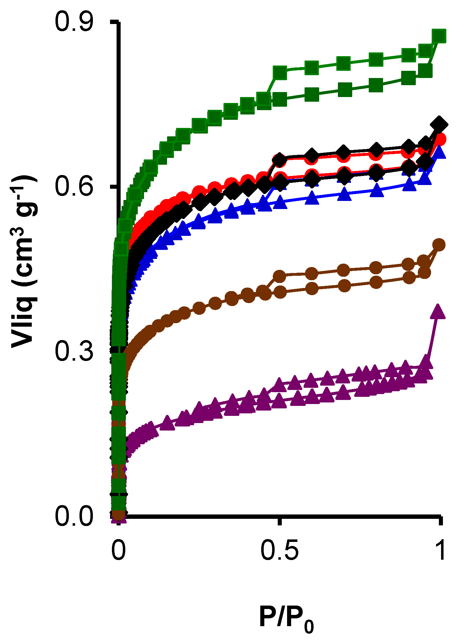 ; CK2-Mn-2-25,
  ; CK2-Mn-2-60, .
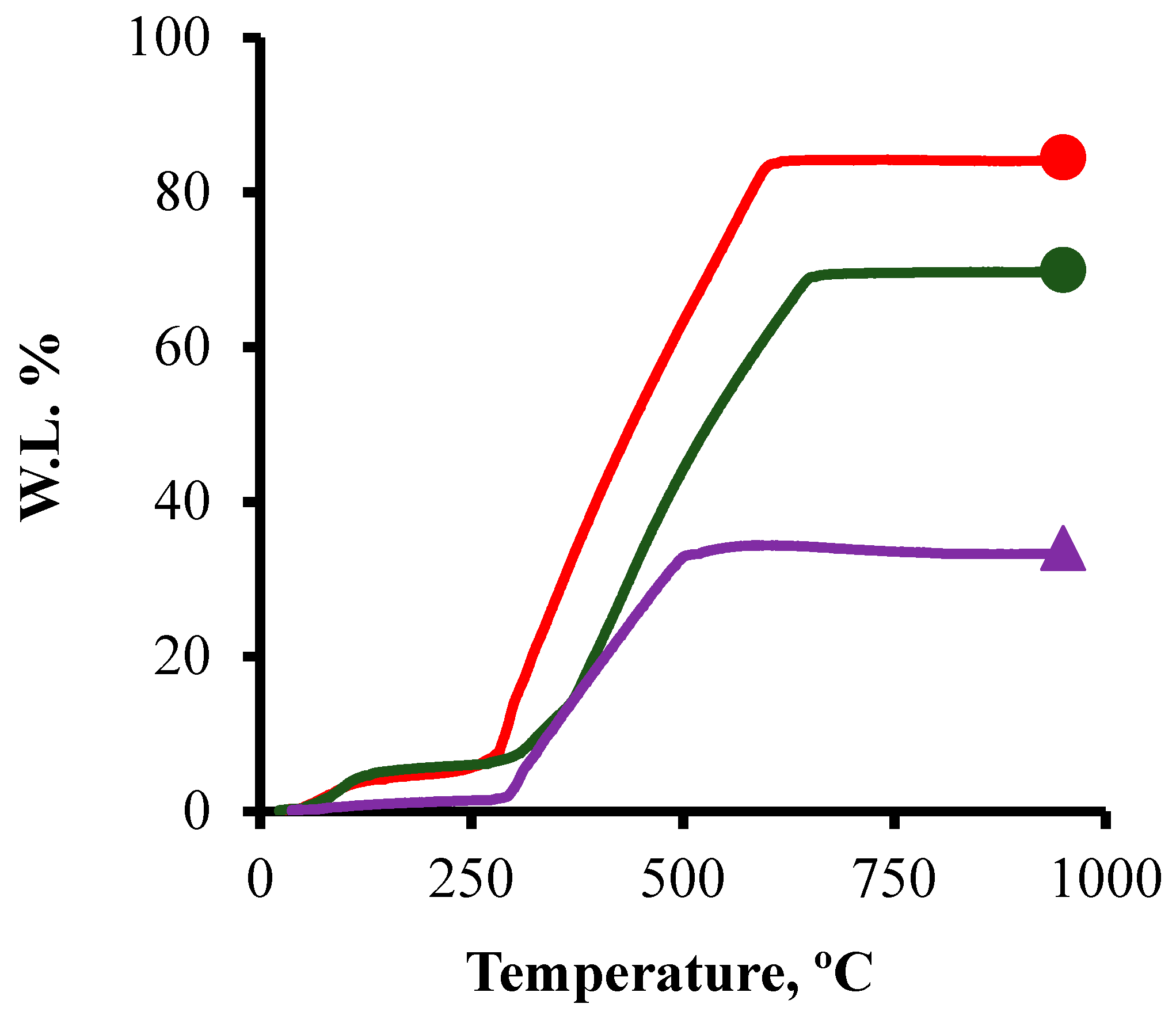
 ; CK2-Mn-2-10, ; CK2-Mn-3-10, ; CK2-Mn-2-25, ; CK2-Mn-2-60, .
; CK2-Mn-2-10, ; CK2-Mn-3-10, ; CK2-Mn-2-25, ; CK2-Mn-2-60, .
; CK2-Mn-2-10, ; CK2-Mn-3-10, ; CK2-Mn-2-25, ; CK2-Mn-2-60, . ; CK2-Mn-2-25, ; CK2-Mn-2-60, .
; CK2-Mn-2-25, ; CK2-Mn-2-60, .
; CK2-Mn-2-25, ; CK2-Mn-2-60, . ; CK2-Mn-1-10, ; CK2-Mn-2-10, ; CK2-Mn-3-10, ; CK2-Mn-2-25, ; CK2-Mn-2-60, .
; CK2-Mn-1-10, ; CK2-Mn-2-10, ; CK2-Mn-3-10, ; CK2-Mn-2-25, ; CK2-Mn-2-60, .
; CK2-Mn-1-10, ; CK2-Mn-2-10, ; CK2-Mn-3-10, ; CK2-Mn-2-25, ; CK2-Mn-2-60, .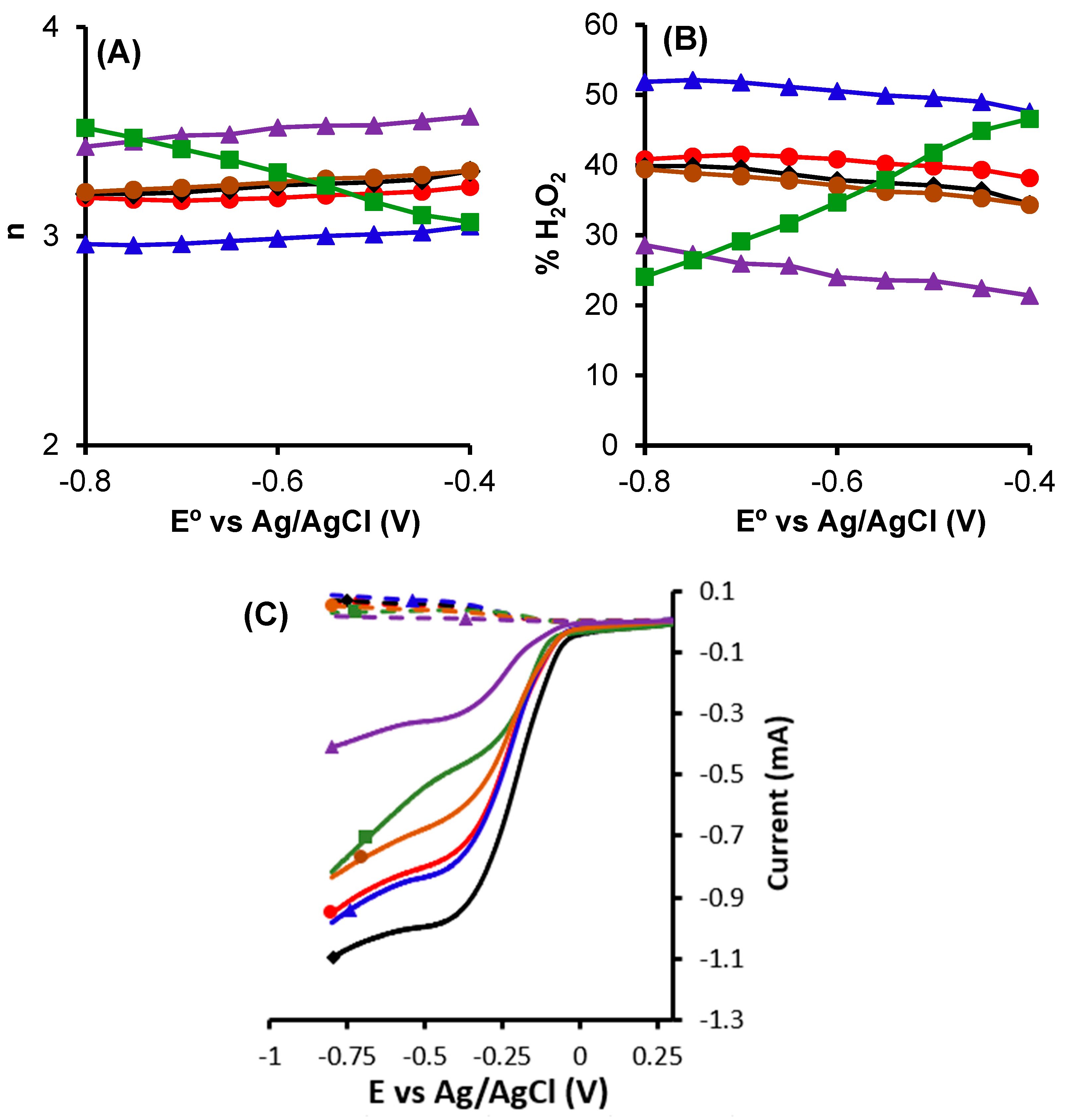
 ; CK2, ; CK2-Mn-1-10, ; CK2-Mn-2-10, ; CK2-Mn-3-10, .
; CK2, ; CK2-Mn-1-10, ; CK2-Mn-2-10, ; CK2-Mn-3-10, .
; CK2, ; CK2-Mn-1-10, ; CK2-Mn-2-10, ; CK2-Mn-3-10, .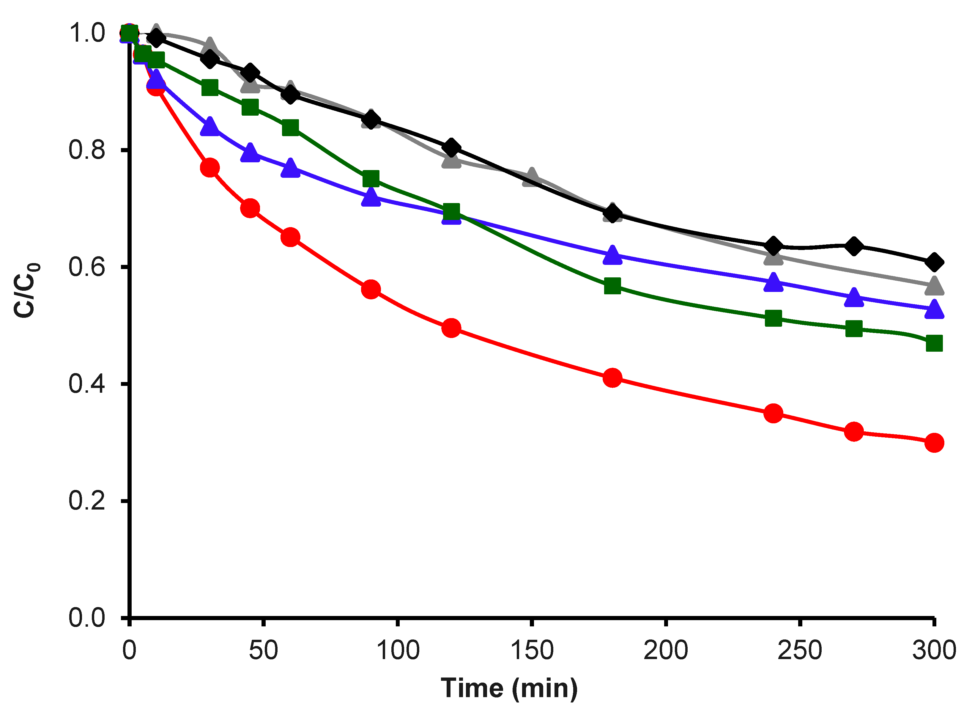 ; CK2-Mn-1-10 in Fenton traditional,
  ; CK2-Mn-1-10 in N2 and H2O2,
  ; H2O2 without catalyst,
  .
; CK2-Mn-1-10 in Fenton traditional, ; CK2-Mn-1-10 in N2 and H2O2, ; H2O2 without catalyst, .
.
; CK2-Mn-1-10 in Fenton traditional, ; CK2-Mn-1-10 in N2 and H2O2, ; H2O2 without catalyst, .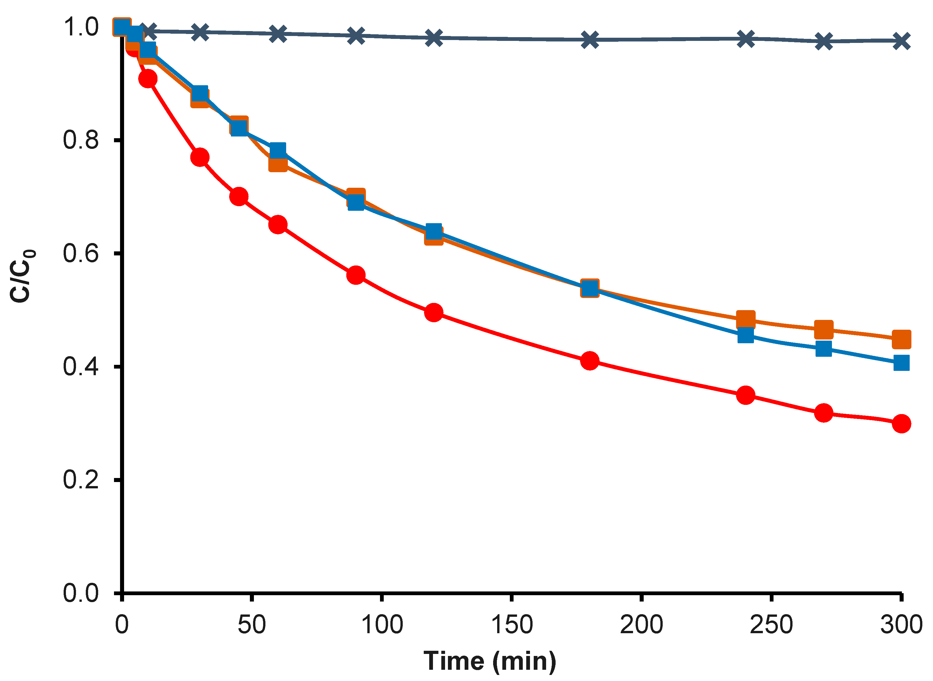 ; CK2-Mn-2-10, ; CK2-Mn-3-10, .
; CK2-Mn-2-10, ; CK2-Mn-3-10, .
; CK2-Mn-2-10, ; CK2-Mn-3-10, .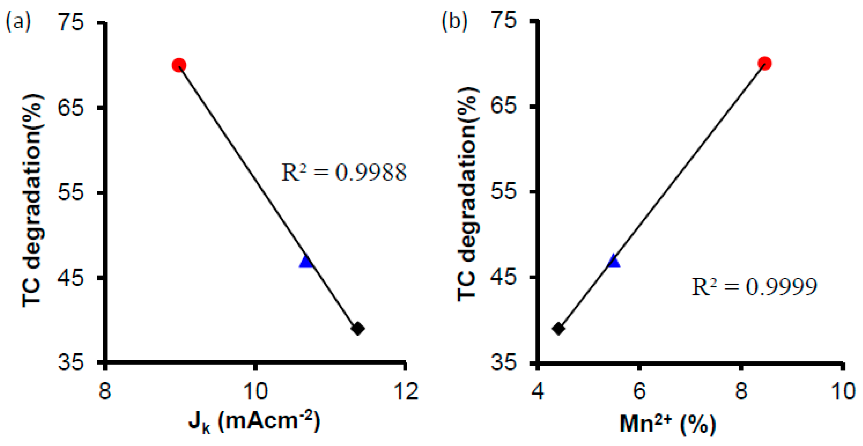

| Samples | N2 | CO2 | |||
|---|---|---|---|---|---|
| SBET | W0 | L0 | W0 | L0 | |
| m2 g−1 | cm3 g−1 | nm | cm3 g−1 | nm | |
| CK2 | 1672 | 0.66 | 1.33 | 0.38 | 0.68 |
| CK2-Mn-1-10 | 1232 | 0.50 | 1.32 | 0.29 | 0.67 |
| CK2-Mn-2-10 | 1380 | 0.56 | 1.33 | 0.31 | 0.67 |
| CK2-Mn-3-10 | 1257 | 0.50 | 1.31 | 0.87 | 1.28 |
| CK2-Mn-2-25 | 945 | 0.37 | 1.33 | 0.22 | 0.82 |
| CK2-Mn-2-60 | 412 | 0.16 | 1.40 | 0.10 | 0.73 |
| Sample | JK (mA cm−2) |
|---|---|
| CK2 | 7.39 |
| CK2-Mn-1-10 | 8.99 |
| CK2-Mn-2-10 | 11.37 |
| CK2-Mn-3-10 | 10.68 |
| CK2-Mn-2-25 | 7.44 |
| CK2-Mn-2-60 | 2.68 |
Disclaimer/Publisher’s Note: The statements, opinions and data contained in all publications are solely those of the individual author(s) and contributor(s) and not of MDPI and/or the editor(s). MDPI and/or the editor(s) disclaim responsibility for any injury to people or property resulting from any ideas, methods, instructions or products referred to in the content. |
© 2024 by the authors. Licensee MDPI, Basel, Switzerland. This article is an open access article distributed under the terms and conditions of the Creative Commons Attribution (CC BY) license (https://creativecommons.org/licenses/by/4.0/).
Share and Cite
Fajardo-Puerto, E.; Elmouwahidi, A.; Bailón-García, E.; Pérez-Cadenas, M.; Pérez-Cadenas, A.F.; Carrasco-Marín, F. Antibiotic Degradation via Fenton Process Assisted by a 3-Electron Oxygen Reduction Reaction Pathway Catalyzed by Bio-Carbon–Manganese Composites. Nanomaterials 2024, 14, 1112. https://doi.org/10.3390/nano14131112
Fajardo-Puerto E, Elmouwahidi A, Bailón-García E, Pérez-Cadenas M, Pérez-Cadenas AF, Carrasco-Marín F. Antibiotic Degradation via Fenton Process Assisted by a 3-Electron Oxygen Reduction Reaction Pathway Catalyzed by Bio-Carbon–Manganese Composites. Nanomaterials. 2024; 14(13):1112. https://doi.org/10.3390/nano14131112
Chicago/Turabian StyleFajardo-Puerto, Edgar, Abdelhakim Elmouwahidi, Esther Bailón-García, María Pérez-Cadenas, Agustín F. Pérez-Cadenas, and Francisco Carrasco-Marín. 2024. "Antibiotic Degradation via Fenton Process Assisted by a 3-Electron Oxygen Reduction Reaction Pathway Catalyzed by Bio-Carbon–Manganese Composites" Nanomaterials 14, no. 13: 1112. https://doi.org/10.3390/nano14131112