
Persistent Luminescent Nanoparticle-Loaded Filaments for Identification of Fabrics in the Visible and Infrared

Abstract
:1. Introduction
2. Materials and Methods
2.1. Nanoparticle Synthesis
2.2. Filament Extrusion
2.3. Spectroscopy
2.4. Filament Testing
2.5. Imaging
3. Results
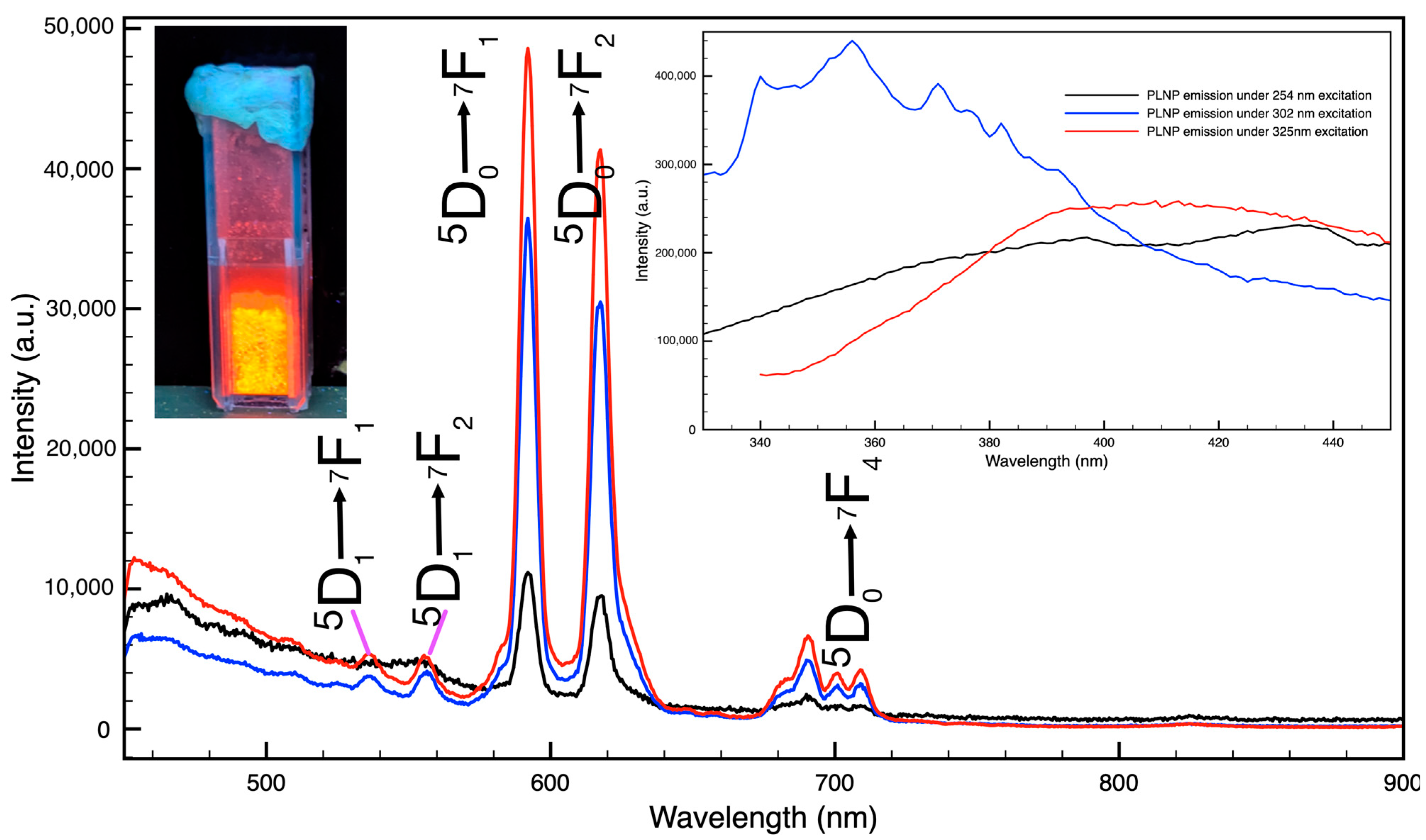
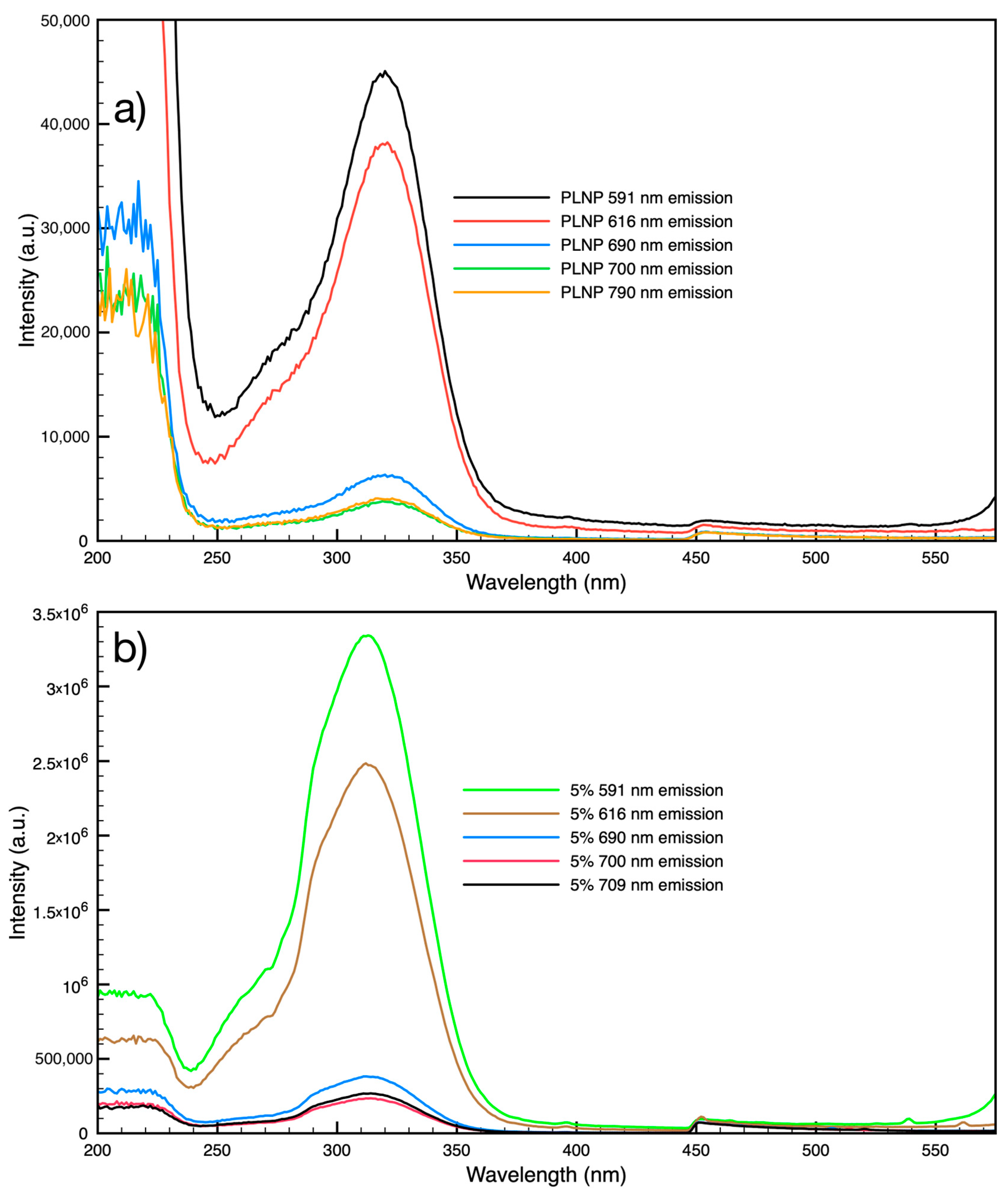
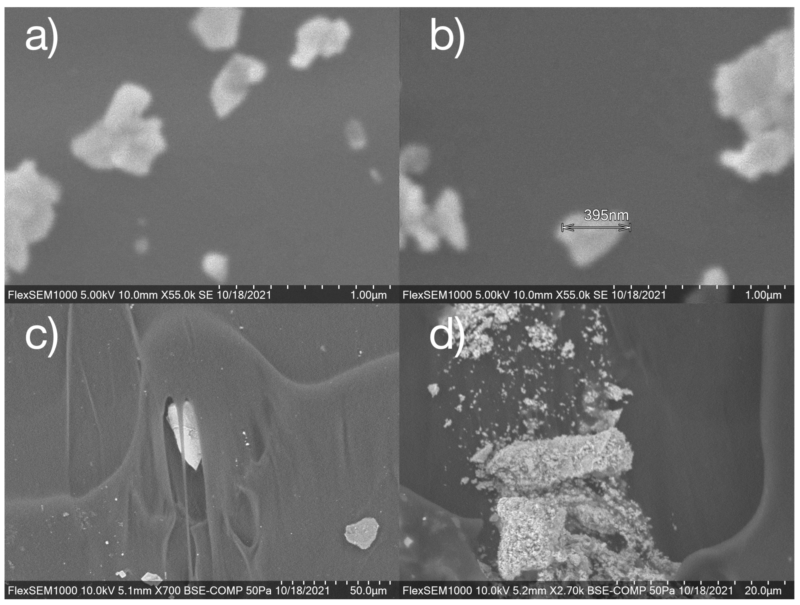
3.1. Persistent Luminescent Nanoparticles (PLNPs)
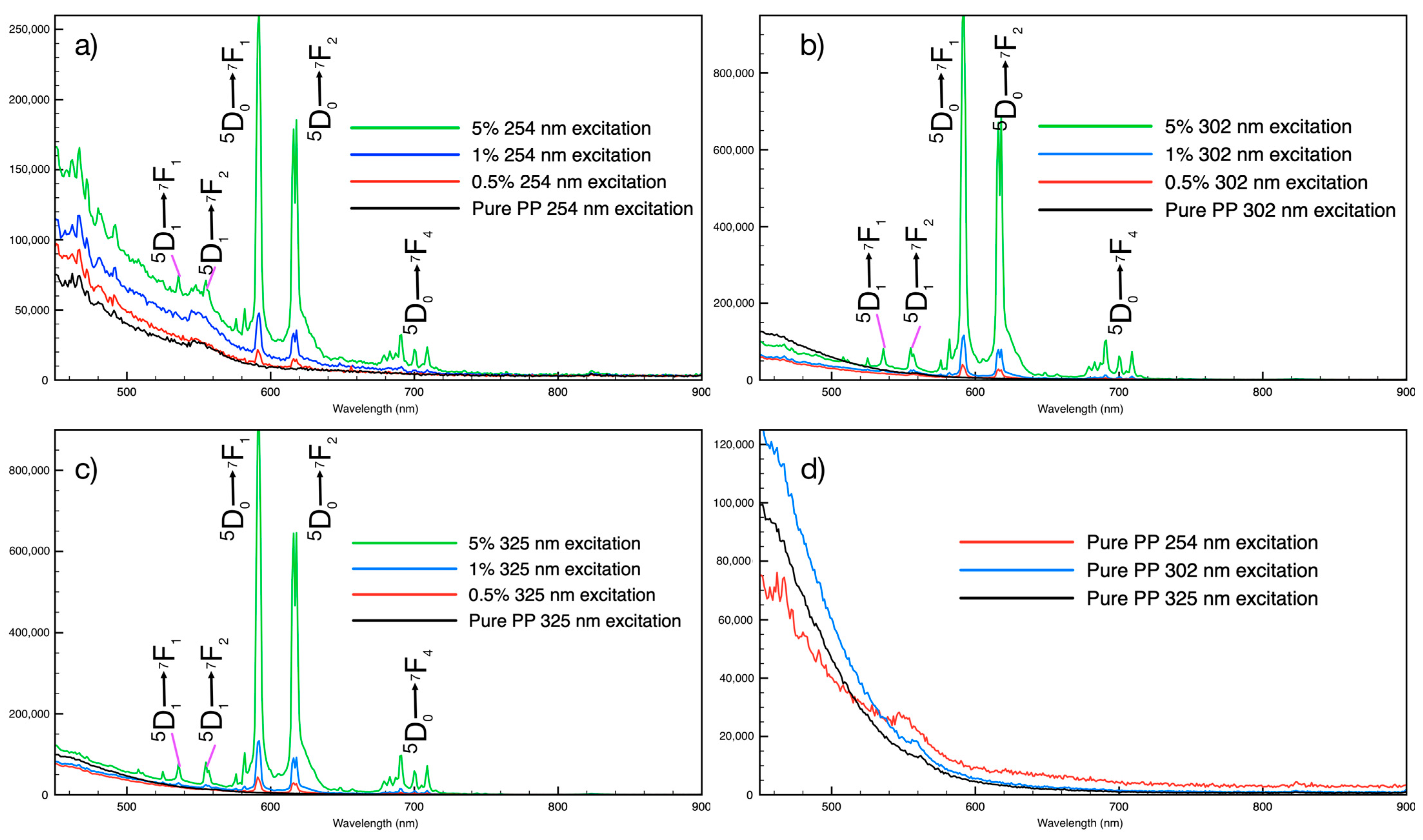
3.2. PLNPs in Filaments
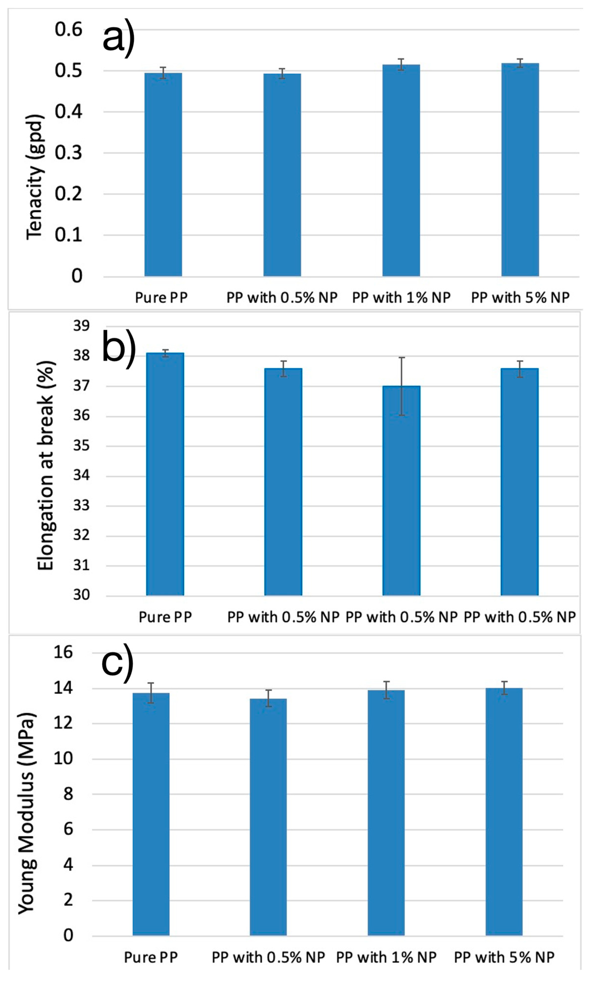
3.3. Mechanical Analysis of Luminescent Filaments
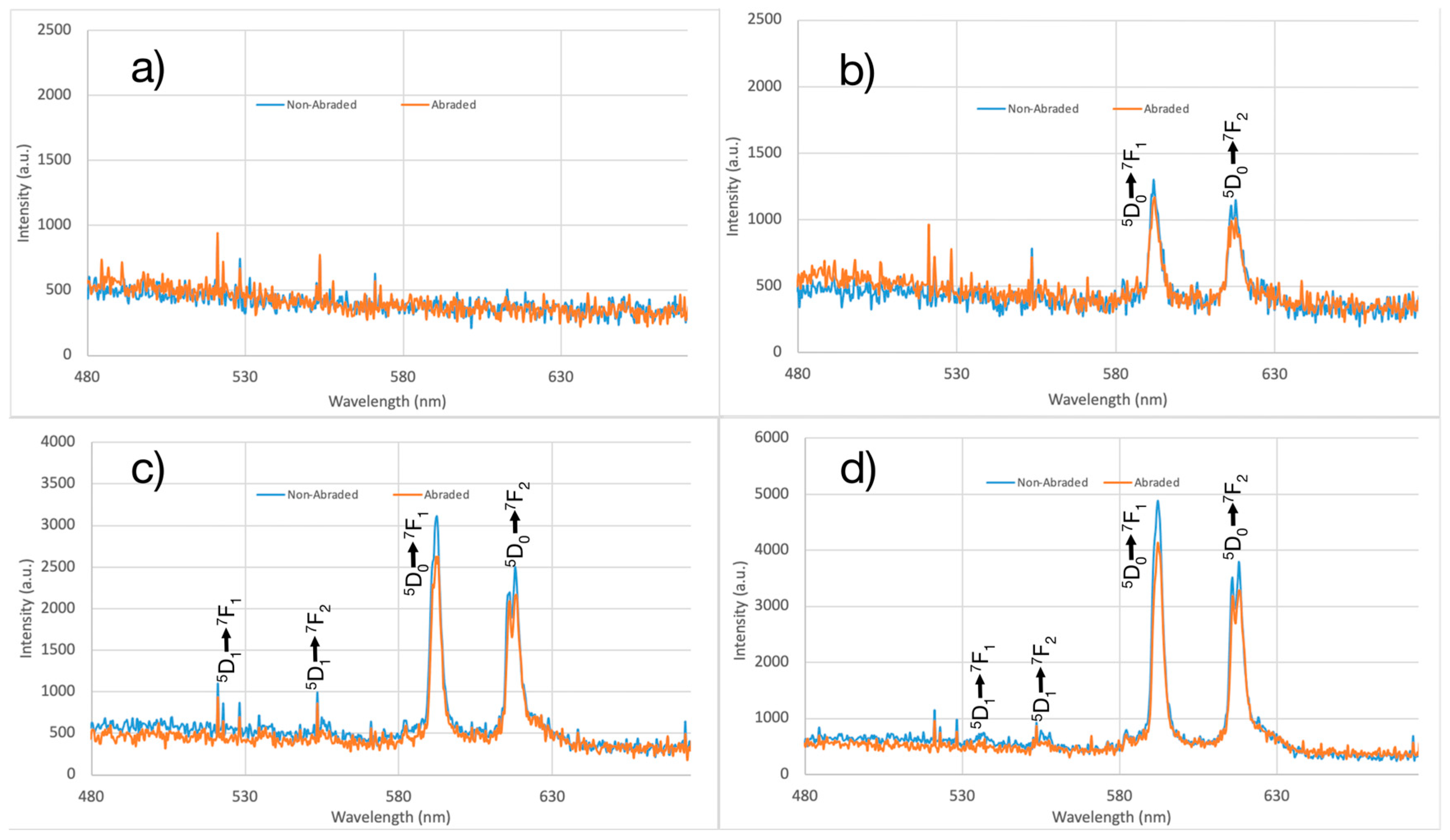
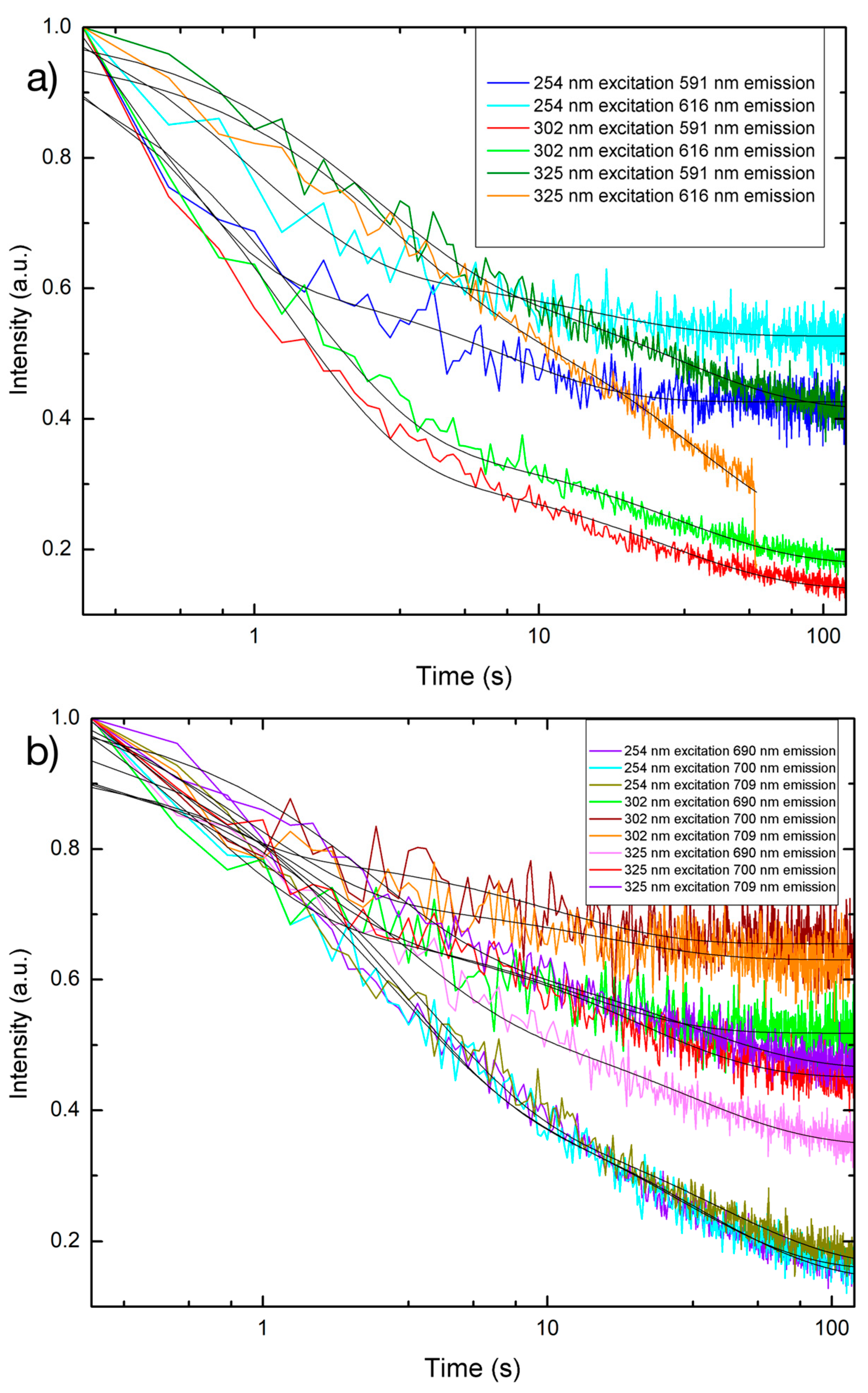
3.4. Persistent Luminescence
4. Conclusions
5. Patents
Author Contributions
Funding
Data Availability Statement
Conflicts of Interest
References
- Kumar, A.; Jayeoye, T.J.; Mohite, P.; Singh, S.; Rajput, T.; Munde, S.; Eze, F.N.; Chidrawar, V.R.; Puri, A.; Prajapati, B.G.; et al. Sustainable and Consumer-Centric Nanotechnology-Based Materials: An Update on the Multifaceted Applications, Risks and Tremendous Opportunities. Nano-Struct. Nano-Objects 2024, 38, 101148. [Google Scholar] [CrossRef]
- Najahi-Missaoui, W.; Arnold, R.D.; Cummings, B.S. Safe Nanoparticles: Are We There Yet? Int. J. Mol. Sci. 2020, 22, 385. [Google Scholar] [CrossRef]
- Khalid Hossain, M.; Hossain, S.; Ahmed, M.H.; Khan, M.I.; Haque, N.; Raihan, G.A. A Review on Optical Applications, Prospects, and Challenges of Rare-Earth Oxides. ACS Appl. Electron. Mater. 2021, 3, 3715–3746. [Google Scholar] [CrossRef]
- Mariselvam, K.; Arun Kumar, R.; Rajeswara Rao, V. Concentration-Dependence and Luminescence Studies of Erbium Doped Barium Lithium Fluoroborate Glasses. Opt. Laser Technol. 2019, 118, 37–43. [Google Scholar] [CrossRef]
- Liang, S.; Wang, H.; Li, Y.; Qin, H.; Luo, Z.; Huang, B.; Zhao, X.; Zhao, C.; Chen, L. Rare-Earth Based Nanomaterials and Their Composites as Electrode Materials for High Performance Supercapacitors: A Review. Sustain. Energy Fuels 2020, 4, 3825–3847. [Google Scholar] [CrossRef]
- Khalid Hossain, M.; Raihan, G.A.; Akbar, M.A.; Rubel, M.H.K.; Ahmed, M.H.; Khan, M.I.; Hossain, S.; Sen, S.K.; Jalal, M.I.E.; El-Denglawey, A. Current Applications and Future Potential of Rare Earth Oxides in Sustainable Nuclear, Radiation, and Energy Devices: A Review. ACS Appl. Electron. Mater. 2022, 4, 3327–3353. [Google Scholar] [CrossRef]
- Venugopal, A.R.; Kaewkhao, J.; Abhiram, J.; Rajashekara, K.M.; Rajaramakrishna, R.; Pramod, N.G.; Rao, C. Eu3+ Ions Doped SrO-CaO-Li2O-B2O3glasses Foroptical Display Material Application. J. Phys. Conf. Ser. 2020, 1485, 012053. [Google Scholar] [CrossRef]
- Matei, E.; Enculescu, M.; Enculescu, I. Single Bath Electrodeposition of Samarium Oxide/zinc Oxide Nanostructured Films with Intense, Broad Luminescence. Electrochim. Acta 2013, 95, 170–178. [Google Scholar] [CrossRef]
- Gupta, S.K.; Sudarshan, K.; Kadam, R.M. Optical Nanomaterials with Focus on Rare Earth Doped Oxide: A Review. Mater. Today Commun. 2021, 27, 102277. [Google Scholar] [CrossRef]
- Hossain, M.K.; Khan, M.I.; El-Denglawey, A. A Review on Biomedical Applications, Prospects, and Challenges of Rare Earth Oxides. Appl. Mater. Today 2021, 24, 101104. [Google Scholar] [CrossRef]
- Skripka, A.; Mendez-Gonzalez, D.; Marin, R.; Ximendes, E.; Del Rosal, B.; Jaque, D.; Rodríguez-Sevilla, P. Near Infrared Bioimaging and Biosensing with Semiconductor and Rare-Earth Nanoparticles: Recent Developments in Multifunctional Nanomaterials. Nanoscale Adv. 2021, 3, 6310–6329. [Google Scholar] [CrossRef] [PubMed]
- Sharma, V.K.; Yngard, R.A.; Lin, Y. Silver Nanoparticles: Green Synthesis and Their Antimicrobial Activities. Adv. Colloid Interface Sci. 2009, 145, 83–96. [Google Scholar] [CrossRef]
- Bindhu, M.R.; Umadevi, M. Antibacterial and Catalytic Activities of Green Synthesized Silver Nanoparticles. Spectrochim. Acta A Mol. Biomol. Spectrosc. 2015, 135, 373–378. [Google Scholar] [CrossRef] [PubMed]
- Simončič, B.; Klemenčič, D. Preparation and Performance of Silver as an Antimicrobial Agent for Textiles: A Review. Text. Res. J. 2015, 86, 210–223. [Google Scholar] [CrossRef]
- Ravindra, S.; Mohan, Y.M.; Reddy, N.N.; Raju, K.M. Fabrication of Antibacterial Cotton Fibres Loaded with Silver Nanoparticles via “Green Approach”. Colloids Surf. A Physicochem. Eng. Asp. 2010, 367, 31–40. [Google Scholar] [CrossRef]
- Bui, V.K.H.; Park, D.; Lee, Y.-C. Chitosan Combined with ZnO, TiO2 and Ag Nanoparticles for Antimicrobial Wound Healing Applications: A Mini Review of the Research Trends. Polymers 2017, 9, 21. [Google Scholar] [CrossRef]
- Abou Elmaaty, T.; El-Nagare, K.; Raouf, S.; Abdelfattah, K.; El-Kadi, S.; Abdelaziz, E. One-Step Green Approach for Functional Printing and Finishing of Textiles Using Silver and Gold NPs. RSC Adv. 2018, 8, 25546–25557. [Google Scholar] [CrossRef]
- Matsuzawa, T.; Aoki, Y.; Takeuchi, N.; Murayama, Y. A New Long Phosphorescent Phosphor with High Brightness, SrAl2O4: Eu2 + , Dy3 +. J. Electrochem. Soc. 1996, 143, 2670–2673. [Google Scholar] [CrossRef]
- Qiu, J.; Li, Y.; Jia, Y. Persistent Phosphors: From Fundamentals to Applications; Woodhead Publishing: Sawston, UK, 2020; ISBN 9780128187722. [Google Scholar]
- Hölsä, J.; Jungner, H.; Lastusaari, M.; Niittykoski, J. Persistent Luminescence of Eu2+ Doped Alkaline Earth Aluminates, MAl2O4:Eu2+. J. Alloys Compd. 2001, 323–324, 326–330. [Google Scholar] [CrossRef]
- Brito, H.F.; Hölsä, J.; Laamanen, T.; Lastusaari, M.; Malkamäki, M.; Rodrigues, L.C.V. Persistent Luminescence Mechanisms: Human Imagination at Work. Opt. Mater. Express OME 2012, 2, 371–381. [Google Scholar] [CrossRef]
- Xu, J.; Tanabe, S. Persistent Luminescence instead of Phosphorescence: History, Mechanism, and Perspective. J. Lumin. 2019, 205, 581–620. [Google Scholar] [CrossRef]
- Yamamoto, H.; Matsuzawa, T. Mechanism of Long Phosphorescence of SrAl2O4:Eu2+, Dy3+ and CaAl2O4:Eu2+, Nd3+. J. Lumin. 1997, 72–74, 287–289. [Google Scholar] [CrossRef]
- Van den Eeckhout, K.; Poelman, D.; Smet, P.F. Persistent Luminescence in Non-Eu2+-Doped Compounds: A Review. Materials 2013, 6, 2789–2818. [Google Scholar] [CrossRef] [PubMed]
- Zhuang, Y.; Katayama, Y.; Ueda, J.; Tanabe, S. A Brief Review on Red to near-Infrared Persistent Luminescence in Transition-Metal-Activated Phosphors. Opt. Mater. 2014, 36, 1907–1912. [Google Scholar] [CrossRef]
- Luo, H.; Bos, A.J.J.; Dorenbos, P. Charge Carrier Trapping Processes in RE2O2S (RE = La, Gd, Y, and Lu). J. Phys. Chem. C 2017, 121, 8760–8769. [Google Scholar] [CrossRef] [PubMed]
- Wang, J.; Ma, Q.; Wang, Y.; Shen, H.; Yuan, Q. Recent Progress in Biomedical Applications of Persistent Luminescence Nanoparticles. Nanoscale 2017, 9, 6204–6218. [Google Scholar] [CrossRef]
- Ryszkowska, J.; Zawadzak, E.A.; Łojkowski, W.; Opalińska, A.; Kurzydłowski, K.J. Structure and Properties of Polyurethane Nanocomposites with Zirconium Oxide Including Eu. Mater. Sci. Eng. C 2007, 27, 994–997. [Google Scholar] [CrossRef]
- Zhao, F.L.; Gao, L.; Wang, C.H.; Xi, P. Electrospinning Preparation and Properties of Tb(phen)L3/PMMA Rare Earth Luminescent Fibers. Appl. Mech. Mater. 2014, 618, 94–99. [Google Scholar] [CrossRef]
- Althues, H.; Simon, P.; Kaskel, S. Transparent and Luminescent YVO4 : Eu/polymer Nanocomposites Prepared by in Situ Polymerization. J. Mater. Chem. 2007, 17, 758–765. [Google Scholar] [CrossRef]
- Goubard, F.; Vidal, F.; Bazzi, R.; Tillement, O.; Chevrot, C.; Teyssie, D. Synthesis and Luminescent Properties of PEO/lanthanide Oxide Nanoparticle Hybrid Films. J. Lumin. 2007, 126, 289–296. [Google Scholar] [CrossRef]
- Sarrazin, P.; Beneventi, D.; Chaussy, D.; Vurth, L.; Stephan, O. Adsorption of Cationic Photoluminescent Nanoparticles on Softwood Cellulose Fibres: Effects of Particles Stabilization and Fibres’ Beating. Colloids Surf. A Physicochem. Eng. Asp. 2009, 334, 80–86. [Google Scholar] [CrossRef]
- Shi, C.; Hou, X.; Li, X.; Ge, M. Preparation and Characterization of Persistent Luminescence of Regenerated Cellulose Fiber. J. Mater. Sci. Mater. Electron. 2016, 28, 1015–1021. [Google Scholar] [CrossRef]
- Shen, X.; Akbarzadeh, A.; Shi, C.; Pang, Z.; Jin, Y.; Ge, M. Preparation and Characterization of Photo-Stimuli-Responsive Fibers Based on Lanthanide-Activated Phosphors and Spiropyran Dye. J. Mater. Res. Technol. 2021, 13, 1374–1387. [Google Scholar] [CrossRef]
- Erdman, A.; Kulpinski, P.; Olejnik, K. Application of Nanocomposite Cellulose Fibers with Luminescent Properties to Paper Functionalization. Cellulose 2016, 23, 2087–2097. [Google Scholar] [CrossRef]
- Yu, H.; Song, H.; Pan, G.; Li, S.; Liu, Z.; Bai, X.; Wang, T.; Lu, S.; Zhao, H. Preparation and Luminescent Properties of Europium-Doped Yttria Fibers by Electrospinning. J. Lumin. 2007, 124, 39–44. [Google Scholar] [CrossRef]
- Ge, M.; Guo, X.; Yan, Y. Preparation and Study on the Structure and Properties of Rare-Earth Luminescent Fiber. Text. Res. J. 2012, 82, 677–684. [Google Scholar] [CrossRef]
- Guo, X.; Zhang, K.; Ge, M. The Luminous Mechanism of Eu2+ and Dy3+ Co-Doped Long Persistent Luminous Fiber. Text. Res. J. 2018, 89, 3601–3609. [Google Scholar] [CrossRef]
- Chen, Z.; Cheng, Q.; Ke, H.; Li, Y.; Wei, Q.; Ge, M. Preparation and Luminescent Properties of Multicolored SrAl2O4:Eu2+, Dy3+/SiO2-Coated Red-Emitting Coumarin Color Converter/polyamide 6 Luminous Fiber with Warm-Toned Luminescence. Text. Res. J. 2020, 90, 1783–1791. [Google Scholar] [CrossRef]
- Barbosa, R.; Gupta, S.K.; Srivastava, B.B.; Villarreal, A.; De Leon, H.; Peredo, M.; Bose, S.; Lozano, K. Bright and Persistent Green and Red Light-Emitting Fine Fibers: A Potential Candidate for Smart Textiles. J. Lumin. 2021, 231, 117760. [Google Scholar] [CrossRef]
- Lin, Y.; Tang, Z.; Zhang, Z.; Nan, C.W. Luminescence of Eu2+ and Dy3+ Activated R3MgSi2O8-Based (R = Ca, Sr, Ba) Phosphors. J. Alloys Compd. 2003, 348, 76–79. [Google Scholar] [CrossRef]
- Gupta, S.K.; Sahu, M.; Krishnan, K.; Saxena, M.K.; Natarajan, V.; Godbole, S.V. Bluish White Emitting Sr2CeO4 and Red Emitting Sr2CeO4:Eu3+ Nanoparticles: Optimization of Synthesis Parameters, Characterization, Energy Transfer and Photoluminescence. J. Mater. Chem. 2013, 1, 7054–7063. [Google Scholar] [CrossRef]
- Wang, W.-N.; Widiyastuti, W.; Ogi, T.; Lenggoro, I.W.; Okuyama, K. Correlations between Crystallite/particle Size and Photoluminescence Properties of Submicrometer Phosphors. Chem. Mater. 2007, 19, 1723–1730. [Google Scholar] [CrossRef]
- Shi, C.; Xue, H.; Zhu, Y.; Ge, M. A Facile Method to Prepare the White Persistent Luminescent Fibers Based on Sr2ZnSi2O7Eu2+, Dy3+ and Fluorescence Pigments. J. Mater. Sci. Mater. Electron. 2018, 29, 9486–9493. [Google Scholar] [CrossRef]
- Silva, M.M.; Lopes, P.E.; Li, Y.; Pötschke, P.; Ferreira, F.N.; Paiva, M.C. Polylactic Acid/Carbon Nanoparticle Composite Filaments for Sensing. NATO Adv. Sci. Inst. Ser. E Appl. Sci. 2021, 11, 2580. [Google Scholar] [CrossRef]
- Meng, S.; He, H.; Jia, Y.; Yu, P.; Huang, B.; Chen, J. Effect of Nanoparticles on the Mechanical Properties of Acrylonitrile-Butadiene-Styrene Specimens Fabricated by Fused Deposition Modeling. J. Appl. Polym. Sci. 2017, 134, 1–9. [Google Scholar] [CrossRef]
- Hu, J.; Wei, H.; Wu, Q.; Zhao, X.; Chen, K.; Sun, J.; Cui, Z.; Wang, C. Preparation and Characterization of Luminescent Polyimide/glass Composite Fiber. J. Mater. Res. Technol. 2022, 18, 4329–4339. [Google Scholar] [CrossRef]
- Poulose, A.M.; Anis, A.; Shaikh, H.; Alhamidi, A.; Siva Kumar, N.; Elnour, A.Y.; Al-Zahrani, S.M. Strontium Aluminate-Based Long Afterglow PP Composites: Phosphorescence, Thermal, and Mechanical Characteristics. Polymers 2021, 13, 1373. [Google Scholar] [CrossRef]
- Xu, J.; Ju, Z.; Yang, X.; Tang, X.; Liu, W. Considerable Improvement of Na2CaSn2Ge3O12:Eu3+ Reddish Orange Long-Persistent Phosphorescence with Co-Doping of Dy3+. Dye. Pigm. 2019, 162, 951–958. [Google Scholar] [CrossRef]


| Sample PLNP Loading Percentage | Denier (g/9000 m) | Weight of 185 mm Length (g) | Diameter (mm) |
|---|---|---|---|
| 0% (Pure PP) | 11,950 | 0.245 ± 0.012 | 1.496 ± 0.0217 |
| 0.5% | 11,960 | 0.246 ± 0.020 | 1.57 ± 0.022 |
| 1.0% | 20,020 | 0.411 ± 0.033 | 1.88 ± 0.048 |
| 5.0% | 20,050 | 0.412 ± 0.038 | 1.91 ± 0.050 |
| Sample PLNP Loading Percentage | Secant Modulus at 2% Strain (MPa) | Secant Modulus at 4% Strain (MPa) |
|---|---|---|
| 0% (Pure PP) | 3.47 | 4.25 |
| 0.5% | 3.01 | 3.75 |
| 1.0% | 1.79 | 2.83 |
| 5.0% | 1.34 | 2.04 |
| Sample, Excitation Wavelength | Emission Wavelength | Decay Constant τ1 (s) ± Standard Error | Decay Constant τ2 (s) ± Standard Error |
|---|---|---|---|
| PLNP, 254 nm | 591 nm | 7.3994 ± 0.5766 | 0.3723 ± 0.0533 |
| PLNP, 254 nm | 616 nm | 14.7525 ± 1.7455 | 0.9653 ± 0.1131 |
| PLNP, 254 nm | 690 nm | 35.0124 ± 0.6946 | 2.6905 ± 0.0847 |
| PLNP, 254 nm | 700 nm | 29.6682 ± 0.9390 | 2.6445 ± 0.1248 |
| PLNP, 254 nm | 709 nm | 40.4209 ± 1.0176 | 3.3752 ± 0.1194 |
| PLNP, 302 nm | 591 nm | 27.4936 ± 0.7038 | 1.2538 ± 0.0367 |
| PLNP, 302 nm | 616 nm | 29.7887 ± 0.7798 | 1.4239 ± 0.0455 |
| PLNP, 302 nm | 690 nm | 12.2215 ± 1.1750 | 0.5984 ± 0.1213 |
| PLNP, 302 nm | 700 nm | 10.2954 ± 1.4042 | 0.3514 ± 0.1351 |
| PLNP, 302 nm | 709 nm | 15.336 ± 2.9839 | 0.8897 ± 0.1938 |
| PLNP, 325 nm | 591 nm | 30.1912 ± 1.5994 | 2.4726 ± 0.1629 |
| PLNP, 325 nm | 616 nm | 35.9099 ± 0.5825 | 2.7200 ± 0.2876 |
| PLNP, 325 nm | 690 nm | 30.9896 ± 0.14515 | 2.6832 ± 0.1719 |
| PLNP, 325 nm | 700 nm | 20.7917 ± 0.8880 | 0.9743 ± 0.1017 |
| PLNP, 325 nm | 709 nm | 31.1097 ± 1.4779 | 2.3018 ± 0.0195 |
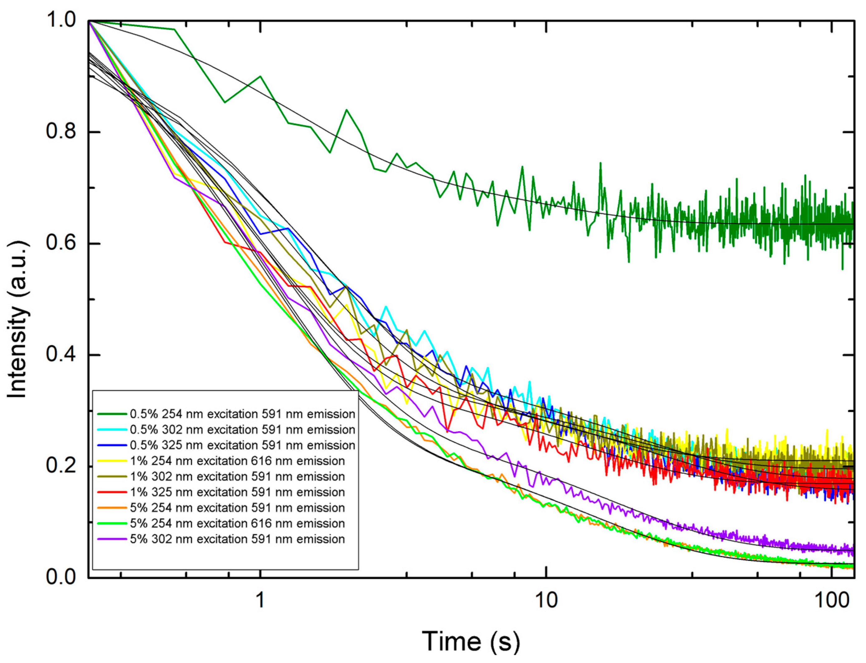
| Sample, Excitation Wavelength | Emission Wavelength | Decay Constant τ1 (s) ± Standard Error | Decay Constant τ2 (s) ± Standard Error |
|---|---|---|---|
| 5% loading, 254 nm | 591 nm | 14.0431 ± 0.2728 | 0.9938 ± 0.0196 |
| 5% loading, 254 nm | 616 nm | 13.9855 ± 0.2713 | 0.9700 ± 0.0197 |
| 5% loading, 254 nm | 690 nm | 16.2753 ± 0.4410 | 1.1097 ± 0.0306 |
| 5% loading, 254 nm | 700 nm | 18.1334 ± 0.6959 | 1.0957 ± 0.0425 |
| 5% loading, 254 nm | 709 nm | 18.2897 ± 0.5481 | 0.8909 ± 0.0288 |
| 5% loading, 302 nm | 591 nm | 17.0090 ± 0.3201 | 1.1343 ± 0.0254 |
| 5% loading, 302 nm | 690 nm | 16.5278 ± 0.6111 | 1.0273 ± 0.0473 |
| 5% loading, 302 nm | 700 nm | 21.1452 ± 0.8600 | 0.9468 ± 0.0545 |
| 5% loading, 302 nm | 709 nm | 21.6270 ± 1.2059 | 1.4183 ± 0.0773 |
| 5% loading, 325 nm | 690 nm | 7.9449 ± 0.5195 | 0.7432 ± 0.0425 |
| 5% loading, 325 nm | 700 nm | 6.9627 ± 0.3380 | 0.6313 ± 0.0276 |
| 5% loading, 325 nm | 709 nm | 8.6477 ± 0.7964 | 0.7321 ± 0.0581 |
| 1% loading, 254 nm | 616 nm | 11.4980 ± 0.7954 | 0.8799 ± 0.0619 |
| 1% loading, 302 nm | 591 nm | 17.4693 ± 0.9230 | 1.2430 ± 0.0585 |
| 1% loading, 325 nm | 591 nm | 12.9628 ± 0.5674 | 0.9274 ± 0.0423 |
| 0.5% loading, 254 nm | 591 nm | 8.7748 ± 2.0564 | 1.1866 ± 0.2717 |
| 0.5% loading, 302 nm | 591 nm | 20.6078 ± 0.6697 | 1.3994 ± 0.0543 |
| 0.5% loading, 325 nm | 591 nm | 22.7326 ± 0.7177 | 1.6070 ± 0.0543 |
Disclaimer/Publisher’s Note: The statements, opinions and data contained in all publications are solely those of the individual author(s) and contributor(s) and not of MDPI and/or the editor(s). MDPI and/or the editor(s) disclaim responsibility for any injury to people or property resulting from any ideas, methods, instructions or products referred to in the content. |
© 2024 by the authors. Licensee MDPI, Basel, Switzerland. This article is an open access article distributed under the terms and conditions of the Creative Commons Attribution (CC BY) license (https://creativecommons.org/licenses/by/4.0/).
Share and Cite
Yust, B.G.; Sk, A.R.; Kontsos, A.; George, B. Persistent Luminescent Nanoparticle-Loaded Filaments for Identification of Fabrics in the Visible and Infrared. Nanomaterials 2024, 14, 1414. https://doi.org/10.3390/nano14171414
Yust BG, Sk AR, Kontsos A, George B. Persistent Luminescent Nanoparticle-Loaded Filaments for Identification of Fabrics in the Visible and Infrared. Nanomaterials. 2024; 14(17):1414. https://doi.org/10.3390/nano14171414
Chicago/Turabian StyleYust, Brian G., Abdur Rahaman Sk, Antonios Kontsos, and Brian George. 2024. "Persistent Luminescent Nanoparticle-Loaded Filaments for Identification of Fabrics in the Visible and Infrared" Nanomaterials 14, no. 17: 1414. https://doi.org/10.3390/nano14171414