


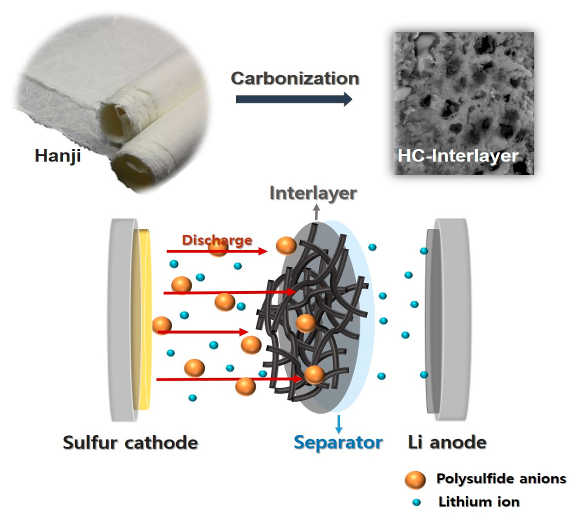
Porous Carbon Interlayer Derived from Traditional Korean Paper for Li–S Batteries

 , and
, and
Abstract
:1. Introduction
2. Materials and Methods
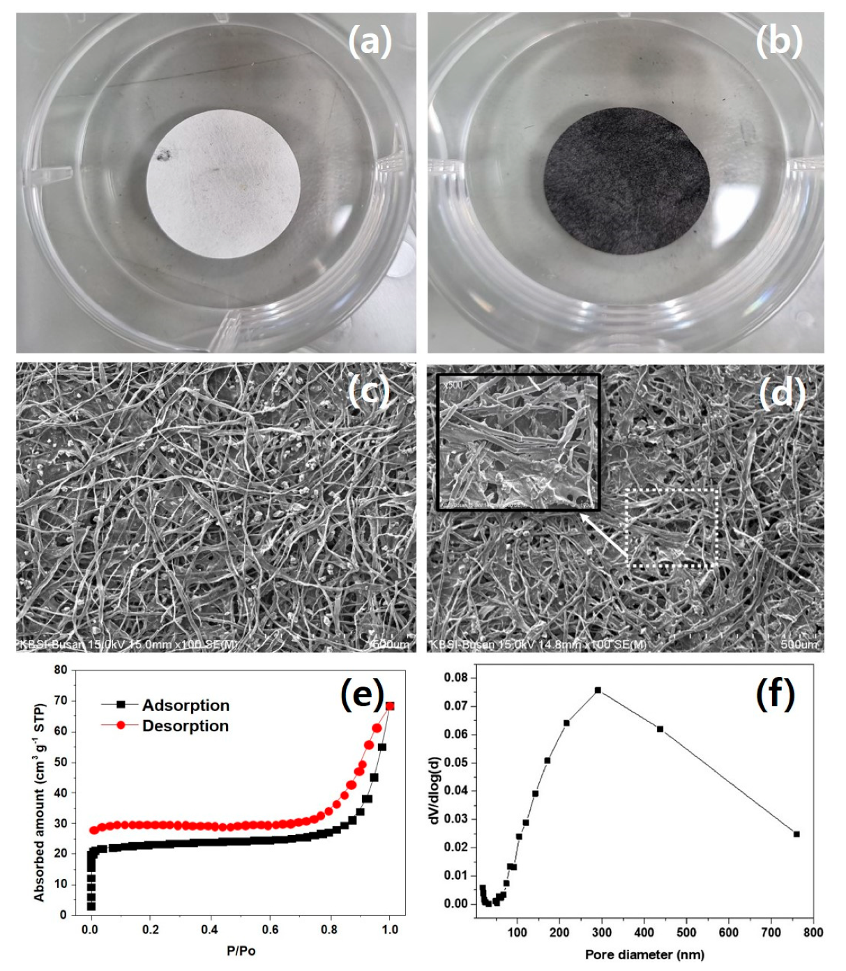
2.1. Preparation of Carbon Interlayer
2.2. Preparation of Flake C-Coated Separator
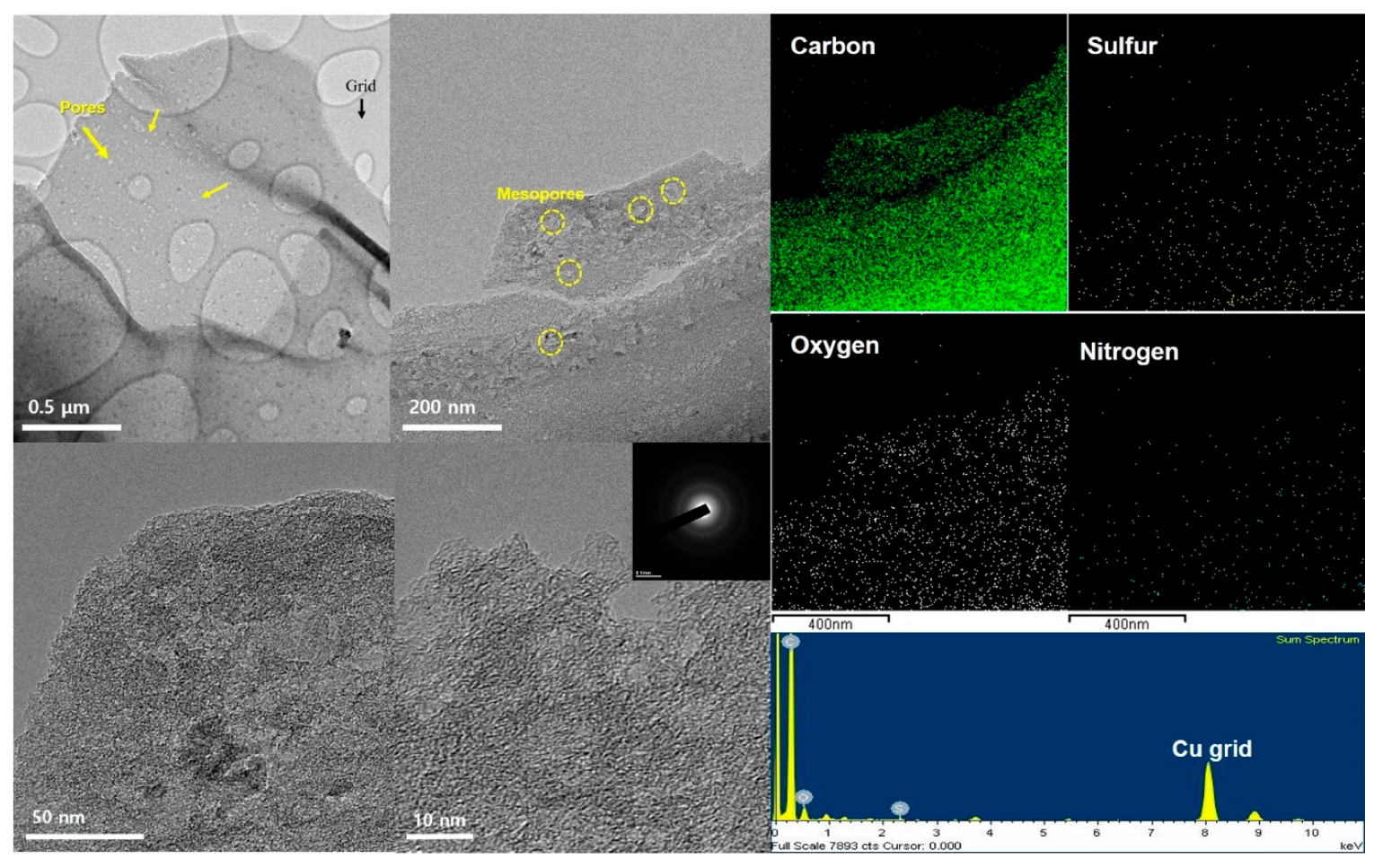
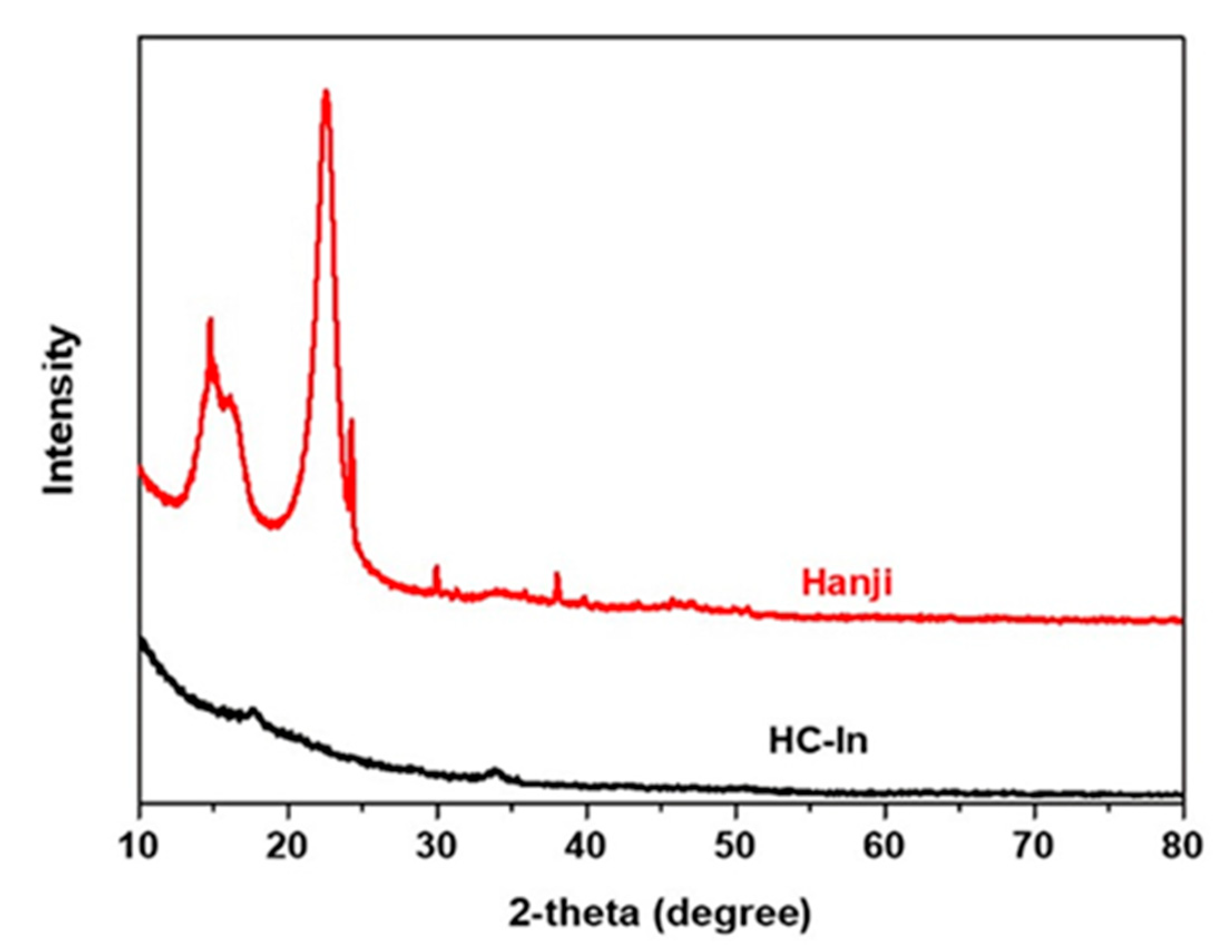
2.3. Material Characterization
2.4. Electrochemical Measurements
3. Results and Discussion
4. Conclusions
Author Contributions
Funding
Data Availability Statement
Conflicts of Interest
References
- Ji, X.; Lee, K.T.; Nazar, L.F. A highly ordered nanostructured carbon-sulphur cathode for lithium-sulphur batteries. Nat. Mater. 2009, 8, 500–506. [Google Scholar] [CrossRef]
- Bruce, P.G.; Freunberger, S.A.; Hardwick, L.J.; Tarascon, J.M. Li-O2 and Li-S batteries with high energy storage. Nat. Mater. 2011, 11, 19–29. [Google Scholar] [CrossRef]
- Wu, H.L.; Huff, L.A.; Esbenshade, J.L.; Gewirth, A.A. In situ EQCM study examining irreversible changes the sulfur-carbon cathode in lithium-sulfur batteries. ACS Appl. Mater. Interfaces 2015, 7, 20820–20828. [Google Scholar] [CrossRef]
- Diao, Y.; Xie, K.; Xiong, S.; Hong, X. Shuttle phenomenon—The irreversible oxidation mechanism of sulfur active material in Li–S battery. J. Power Sources 2013, 235, 181–186. [Google Scholar] [CrossRef]
- Xu, G.; Ding, B.; Pan, J.; Nie, P.; Shen, L.; Zhang, X. High performance lithium–sulfur batteries: Advances and challenges. J. Mater. Chem. A 2014, 2, 12662–12676. [Google Scholar] [CrossRef]
- Zheng, D.; Qu, D.; Yang, X.-Q.; Yu, X.; Lee, H.-S.; Qu, D. Quantitative and qualitative determination of polysulfide species in the electrolyte of a lithium–sulfur battery using HPLC ESI/MS with one-step derivatization. Adv. Energy Mater. 2015, 5, 1401888. [Google Scholar] [CrossRef]
- Choi, Y.; Lee, S.Y.; Bae, J.S.; Lee, S.J.; Kim, H.K.; Jeong, E.D.; Shin, H. Nitrogen and sulfur co-doped porous carbon derived from thiourea and calcium citrate for lithium-sulfur batteries. Appl. Sci. 2020, 10, 1263. [Google Scholar] [CrossRef]
- Lee, S.Y.; Choi, Y.; Kim, J.K.; Lee, S.J.; Bae, J.S.; Jeong, E.D. Biomass-garlic-peel-derived porous carbon framework as a sulfur host for lithium-sulfur batteries. J. Ind. Eng. Chem. 2021, 94, 272–281. [Google Scholar] [CrossRef]
- Kim, J.K.; Choi, Y.; Jeong, E.D.; Lee, S.J.; Kim, H.G.; Chung, J.M.; Kim, J.S.; Lee, S.Y.; Bae, J.S. Synthesis and electrochemical performance of microporous hollow carbon from milkweed pappus as cathode material of lithium–sulfur batteries. Nanomaterials 2022, 12, 3605. [Google Scholar] [CrossRef]
- Zhao, F.; Xue, J.; Shao, W.; Yu, H.; Huang, W.; Xiao, J. Towards high-sulfur-content, high-performance lithium–sulfur batteries: Review of materials and technologies. J. Energy Chem. 2023, 80, 625–657. [Google Scholar] [CrossRef]
- Li, W.; Hicks-Garner, J.; Wang, J.; Liu, J.; Gross, A.F.; Sherman, E.; Graetz, J.; Vajo, J.J.; Liu, P. V2O5 polysulfide anion barrier for long-lived Li–S batteries. Chem. Mater. 2014, 26, 3403–3410. [Google Scholar] [CrossRef]
- Yao, H.; Yan, K.; Li, W.; Zheng, G.; Kong, D.; Seh, Z.W.; Narasimhan, V.K.; Liang, Z.; Cui, Y. Improved lithium–sulfur batteries with a conductive coating on the separator to prevent the accumulation of inactive S-related species at the cathode–separator interface. Energy Environ. Sci. 2014, 7, 3381–3390. [Google Scholar] [CrossRef]
- Zhou, G.; Pei, S.; Li, L.; Wang, D.W.; Wang, S.; Huang, K.; Yin, L.C.; Li, F.; Cheng, H.M. Batteries: A graphene–pure-sulfur sandwich structure for ultrafast, long-life lithium–sulfur batteries. Adv. Mater. 2014, 26, 664. [Google Scholar] [CrossRef] [PubMed]
- Xing, L.-B.; Xi, K.; Li, Q.; Su, Z.; Lai, C.; Zhao, X.; Kumar, R.V. Nitrogen, sulfur-codoped graphene sponge as electroactive carbon interlayer for high-energy and -power lithium–sulfur batteries. J. Power Sources 2016, 303, 22–28. [Google Scholar] [CrossRef]
- Singhal, R.; Chung, S.-H.; Manthiram, A.; Kalra, V. A free-standing carbon nanofiber interlayer for high-performance lithium–sulfur batteries. J. Mater. Chem. A 2015, 3, 4530–4538. [Google Scholar] [CrossRef]
- Su, Y.S.; Manthiram, A. A new approach to improve cycle performance of rechargeable lithium–sulfur batteries by inserting a free-standing MWCNT interlayer. Chem. Commun. 2012, 48, 8817–8819. [Google Scholar] [CrossRef] [PubMed]
- Su, Y.; Manthiram, A. Lithium–sulphur batteries with a microporous carbon paper as a bifunctional interlayer. Nat. Commun. 2012, 3, 1166. [Google Scholar] [CrossRef]
- Zu, C.; Su, Y.S.; Fu, Y.; Manthiram, A. Improved lithium-sulfur cells with a treated carbon paper interlayer. Phys. Chem. Chem. Phys. 2013, 15, 2291–2297. [Google Scholar] [CrossRef]
- Kong, L.L.; Zhang, Z.; Zhang, Y.Z.; Liu, S.; Li, G.R.; Gao, X.P. Porous carbon paper as interlayer to stabilize the lithium anode for lithium-sulfur battery. ACS Appl. Mater. Interfaces 2016, 8, 31684–31694. [Google Scholar] [CrossRef]
- Quay, Y.J.; Chung, S.H. Structural and surfacial modification of carbon nanofoam as an interlayer for electrochemically stable lithium-sulfur cells. Nanomaterials 2021, 11, 3342. [Google Scholar] [CrossRef]
- Saroha, R.; Oh, J.H.; Seon, Y.H.; Kang, Y.C.; Lee, J.S.; Jeong, D.W.; Cho, J.S. Freestanding interlayers for Li–S batteries: Design and synthesis of hierarchically porous N-doped C nanofibers comprising vanadium nitride quantum dots and MOF-derived hollow N-doped C nanocages. J. Mater. Chem. A 2021, 9, 11651–11664. [Google Scholar] [CrossRef]
- Wu, X.L.; Wen, T.; Guo, H.L.; Yang, S.; Wang, X.; Xu, A.W. Biomass-derived sponge-like carbonaceous hydrogels and aerogels for supercapacitors. ACS Nano 2013, 7, 3589–3597. [Google Scholar] [CrossRef] [PubMed]
- Wu, Z.Y.; Li, C.; Liang, H.W.; Chen, J.F.; Yu, S.H. Ultralight, Flexible, and Fire-Resistant Carbon Nanofiber Aerogels from Bacterial Cellulose. Angew. Chem. 2013, 125, 2997–3001. [Google Scholar] [CrossRef]
- Gu, X.; Lai, C.; Liu, F.; Yang, W.; Hou, Y.; Zhang, S. A conductive interwoven bamboo carbon fiber membrane for Li–S batteries. J. Mater. Chem. A 2015, 3, 9502–9509. [Google Scholar] [CrossRef]
- Zhang, K.; Li, Q.; Zhang, L.; Fang, J.; Li, J.; Qin, F.; Zhang, Z.; Lai, Y. From filter paper to carbon paper and toward Li–S battery interlayer. Mater. Lett. 2014, 121, 198–201. [Google Scholar] [CrossRef]
- Jeong, S.H. A study on manufacturing technologies and excellence of Korean traditional paper. MUNHWAJAE Kor. J. Cult. Heritage Stud. 2015, 48, 96–131. [Google Scholar] [CrossRef]
- Yang, K.; Zhong, L.; Guan, R.; Xiao, M.; Han, D.; Wang, S.; Meng, Y. Carbon felt interlayer derived from rice paper and its synergistic encapsulation of polysulfides for lithium-sulfur batteries. Appl. Surf. Sci. 2018, 441, 914–922. [Google Scholar] [CrossRef]
- Oh, C.; Yoon, N.; Choi, J.; Choi, Y.; Ahn, S.; Lee, J.K. Enhanced Li–S battery performance based on solution-impregnation-assisted sulfur/mesoporous carbon cathodes and a carbon-coated separator. J. Mater. Chem. A 2017, 5, 5750–5760. [Google Scholar] [CrossRef]
- Chen, L.F.; Huang, Z.H.; Liang, H.W.; Guan, Q.F.; Yu, S.H. Bacterial-cellulose-derived carbon nanofiber@MnO₂ and nitrogen-doped carbon nanofiber electrode materials: An asymmetric supercapacitor with high energy and power density. Adv. Mater. 2013, 25, 4746–4752. [Google Scholar] [CrossRef]
- Cengiz, E.C.; Salihoglu, O.; Ozturk, O.; Kocabas, C.; Demir-Cakan, R. Ultra-lightweight Chemical Vapor Deposition grown multilayered graphene coatings on paper separator as interlayer in lithium-sulfur batteries. J. Alloys Compd. 2019, 777, 1017–1024. [Google Scholar] [CrossRef]
- Cao, Z.; Ma, C.; Yin, Y.; Zhang, J.; Ding, Y.; Shi, M.; Yang, S. Carbonized non-woven fabric films as adsorbing interlayers to enhance electrochemical performance of lithium–sulfur batteries. New J. Chem. 2015, 39, 9659–9664. [Google Scholar] [CrossRef]
- Jiang, S.J.; Wu, C.X.; Liu, R.; Wang, J.; Xu, Y.S.; Cao, F.F. Multifunctional Interlayer Engineering for Silkworm Excrement-Derived Porous Carbon Enabling High-Energy Lithium Sulfur Batteries. ChemSusChem 2024, 17, e202301110. [Google Scholar] [CrossRef] [PubMed]
- Choi, J.M.; Saroha, R.; Kim, J.S.; Jang, M.R.; Cho, J.S. Porous nanofibers comprising VN nanodots and densified N-doped CNTs as redox-active interlayers for Li–S batteries. J. Power Sources 2023, 559, 232632. [Google Scholar] [CrossRef]
- Feng, G.; Liu, X.; Wu, Z.; Chen, Y.; Yang, Z.; Wu, C.; Guo, X.; Zhong, B.; Xiang, W.; Li, J. Enhancing performance of Li–S batteries by coating separator with MnO@ yeast-derived carbon spheres. J. Alloys Compd. 2020, 817, 152723. [Google Scholar] [CrossRef]

| Description | Sulfur Content (%) | Mass Loading | Initial Capacities (mAh g−1) | Capacity (mAh g−1) | Ref. |
|---|---|---|---|---|---|
| CVD graphene | 63 | 8 μg cm-2 | 1039 | C dis = 619 mAh g−1 Cycle number = 100 Rate = 0.2 C | [30] |
| Nonwoven carbon fiber fabric | 70 | - | 1486 | C dis = 858 mAh g−1 Cycle number = 100 Rate = 0.1 C | [31] |
| Silkworm excrement-derived porous carbon | 80 | - | 1295.1 | C dis = 786 mAh g−1 Cycle number = 100 Rate = 0.2 C | [32] |
| Vanadium nitride nanodots CNT | 70 | ~0.6 mg cm-2 | 1097 | C dis = 432 mAh g−1 Cycle number = 400 Rate = 0.1 C | [33] |
| Yeast | 70 | ~0.46 mg cm-2 | 800.2 | C dis = 642 mAh g−1 Cycle number = 100 Rate = 0.1 C | [34] |
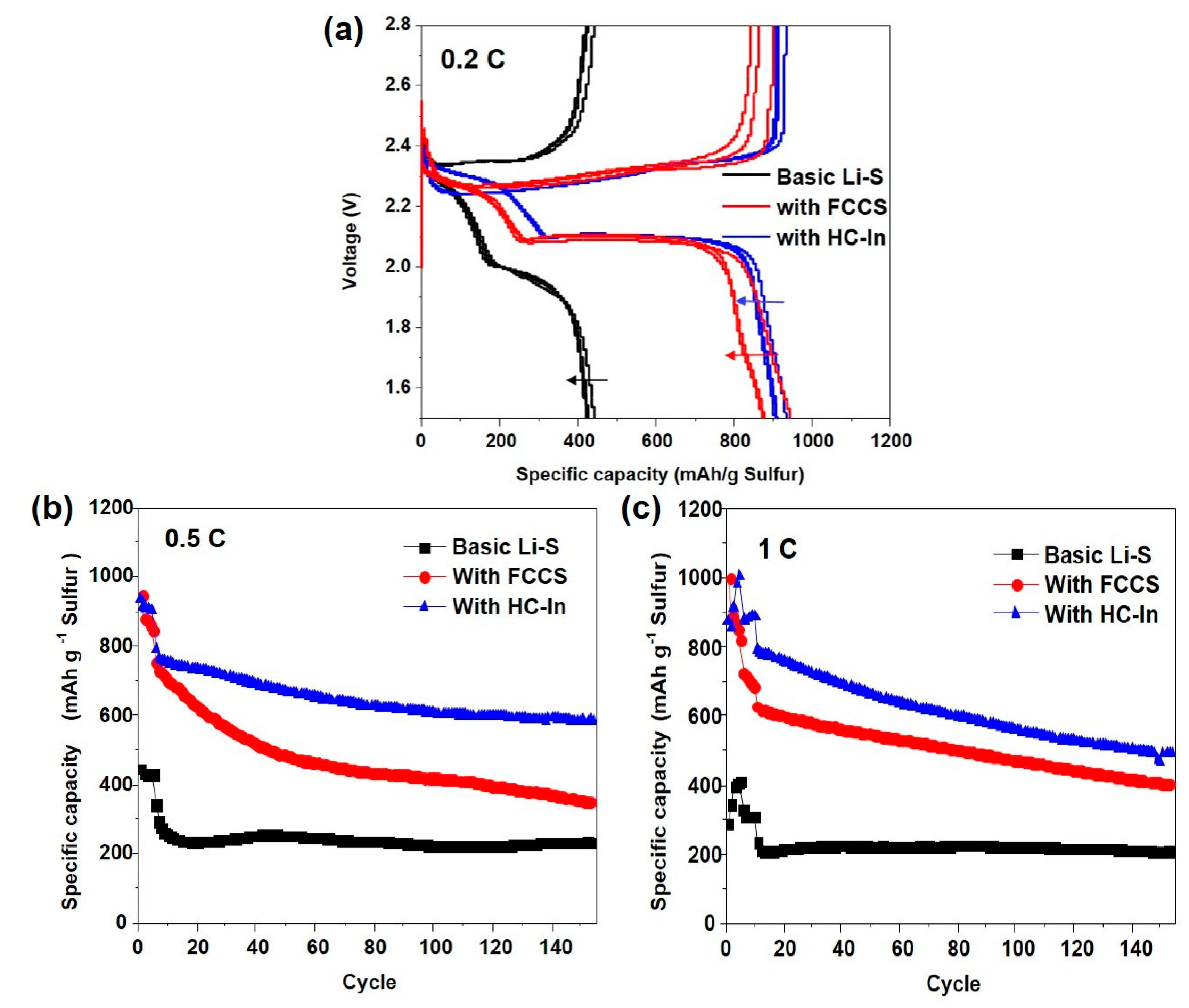
| HC−In | 70 | ~2.2 mg cm-2 | 935 | C dis = 604 mAh g−1 Cycle number = 100 Rate = 0.5 C | This work |
Disclaimer/Publisher’s Note: The statements, opinions and data contained in all publications are solely those of the individual author(s) and contributor(s) and not of MDPI and/or the editor(s). MDPI and/or the editor(s) disclaim responsibility for any injury to people or property resulting from any ideas, methods, instructions or products referred to in the content. |
© 2024 by the authors. Licensee MDPI, Basel, Switzerland. This article is an open access article distributed under the terms and conditions of the Creative Commons Attribution (CC BY) license (https://creativecommons.org/licenses/by/4.0/).
Share and Cite
Choi, Y.; Jang, H.; Kim, J.-P.; Lee, J.; Jeong, E.D.; Bae, J.-S.; Shin, H.-C. Porous Carbon Interlayer Derived from Traditional Korean Paper for Li–S Batteries. Nanomaterials 2024, 14, 385. https://doi.org/10.3390/nano14040385
Choi Y, Jang H, Kim J-P, Lee J, Jeong ED, Bae J-S, Shin H-C. Porous Carbon Interlayer Derived from Traditional Korean Paper for Li–S Batteries. Nanomaterials. 2024; 14(4):385. https://doi.org/10.3390/nano14040385
Chicago/Turabian StyleChoi, Yunju, Hyungil Jang, Jong-Pil Kim, Jaeyeong Lee, Euh Duck Jeong, Jong-Seong Bae, and Heon-Cheol Shin. 2024. "Porous Carbon Interlayer Derived from Traditional Korean Paper for Li–S Batteries" Nanomaterials 14, no. 4: 385. https://doi.org/10.3390/nano14040385
APA StyleChoi, Y., Jang, H., Kim, J.-P., Lee, J., Jeong, E. D., Bae, J.-S., & Shin, H.-C. (2024). Porous Carbon Interlayer Derived from Traditional Korean Paper for Li–S Batteries. Nanomaterials, 14(4), 385. https://doi.org/10.3390/nano14040385