Article

Hybrid-Mechanism Synergistic Flexible Nb2O5@WS2@C Carbon Nanofiber Anode for Superior Sodium Storage

1
School of Physics and Materials Science, Guangzhou University, Guangzhou 510006, China
2
Research Center for Advanced Information Materials (CAIM), Huangpu Research & Graduate School of Guangzhou University, Guangzhou 510555, China
3
Joint Institute of Guangzhou University & Institute of Corrosion Science and Technology, Guangzhou University, Guangzhou 510275, China
*
Authors to whom correspondence should be addressed.
Nanomaterials 2024, 14(7), 631; https://doi.org/10.3390/nano14070631
Submission received: 8 March 2024 / Revised: 30 March 2024 / Accepted: 2 April 2024 / Published: 5 April 2024

Abstract

:
Sodium-ion batteries (SIBs) have demonstrated remarkable development potential and commercial prospects. However, in the current state of research, the development of high-energy-density, long-cycle-life, high-rate-performance anode materials for SIBs remains a huge challenge. Free-standing flexible electrodes, owing to their ability to achieve higher energy density without the need for current collectors, binders, and conductive additives, have garnered significant attention across various fields. In this work, we designed and fabricated a free-standing three-dimensional flexible Nb2O5@WS2@C carbon nanofiber (CNF) anode based on a hybrid adsorption–intercalation–conversion mechanism of sodium storage, using electrospinning and hydrothermal synthesis processes. The hybrid structure, aided by synergistic effects, releases the advantages of all materials, demonstrating a superior rate performance (288, 248, 211, 158, 90, and 48 mA h g−1 at the current density of 0.2, 0.5, 1, 2, 5, and 10 A g−1, respectively) and good cycling stability (160 mA h g−1 after 200 cycles at 1 A g−1). This work provides certain guiding significance for future research on hybrid and flexible anodes of SIBs.

1. Introduction

Due to the growing fossil energy crisis and environmental pollution problems, green and non-polluting renewable energy sources are developing rapidly [1,2]. In particular, rechargeable batteries have been widely used in areas such as removable electronic devices and electric vehicles [3,4]. However, lithium-ion batteries (LIBs), which are the most widely used rechargeable batteries, are commercially limited due to lower crustal abundance and higher prices [5,6]. Sodium-ion batteries (SIBs) are currently considered as a potential alternative to LIBs due to their low cost and their similar electrochemical mechanism to LIBs [7]. However, due to the larger radius and slow diffusion kinetics of sodium ions compared to lithium ions, commercially available graphite anodes cannot be directly used for SIBs, and there is an urgent need to develop new high-performance anodes for SIBs [8,9,10].
Currently, the research on anodes for SIBs can be mainly classified into three main categories, namely alloy-based, conversion-based, and intercalation-based, according to the different mechanisms of sodium storage [11,12]. Among them, alloy-based anode materials, including Sn and Sb, undergo an alloying reaction during sodium storage and have high theoretical specific capacity and low operating voltage. However, the substantial volume changes during the alloying–dealloying reaction of sodium ions can significantly impact the sodium storage performance of these materials [13,14]. Conversion-based anode materials undergo a phase transition during charging and discharging, and the conversion reaction is a multi-electron-transfer process, so they have a high specific capacity. Common materials include CuO and MoS2. However, they also face some drawbacks, such as poor rate performance and large volume expansion [15,16,17]. Intercalation-based anode materials are based on the intercalation mechanism, and most of them have lower theoretical specific capacity, but they show excellent rate performance and cycle stability performance with less volume expansion during the charging and discharging process. Typical anode materials for intercalation-based SIBs include titanium-based oxides (e.g., TiO2) and niobium-based oxides (e.g., Nb2O5) [18,19]. All three types of sodium storage materials have their advantages and disadvantages. Current research focuses on how to highlight the advantages and exclude the disadvantages of each material, which is the main direction of SIB anode material research.
In this study, we designed and prepared a hybrid SIBs anode material, denoted as Nb2O5@WS2@C CNFs. This electrode material contains four different components: hard carbon, Nb2O5, WS2, and soft carbon. Among them, hard carbon has become the most widely used anode electrode material for SIBs because of its wide availability and low price [20]. Its sodium-ion storage mechanism based on adsorption (sloping region, above 0.1 V vs. Na+/Na)–intercalation (plateau region, below 0.1 V vs. Na+/Na) gives it a stable structure and cycling stability but also limits its specific capacity [18,20,21]. Orthorhombic Nb2O5 is a typical layered material with intercalation behavior, featuring abundant intercalation sites internally; it can be utilized for the storage of lithium ions and sodium ions [22,23]. Recent studies have indicated that it serves as an outstanding energy storage anode with high rate capability and long cycling performance [24,25]. Transition metal dichalcogenides (MoS2, WS2, etc.) have extremely high theoretical capacities due to their distinct layer structure similar to graphite and conversion-based sodium storage mechanism [26,27]. However, the large volume expansion leads to a drastic capacity decay [16,28,29,30]. The incorporation of soft carbon significantly improves the conductivity and mitigates the volume expansion [31]. An electrode coupled with hybrid-mechanism synergistic effects has been certified in our previous work to achieve excellent sodium storage performances [18]. On this basis, this work compounded Nb2O5, WS2, CNFs, and soft carbon to prepare a Nb2O5@WS2@C CNF hybrid-mechanism anode. Ultimately, the free-standing flexible electrodes have exhibited excellent rate performance and cycling stability.

2. Materials and Methods

2.1. Materials

Niobium ethoxide (Nb(C2H5O)5, 99.95% trace metals basis), polyacrylonitrile (PAN, average Mw = 150,000), ammonium tetrathiotungstate ((NH4)2WS4, 99.9%), anhydrous glucose (99.5%), and N, N-dimethylformamide (DMF, 99%) were purchased from commercial sources and used without any further purification.

2.2. Synthesis of Nb2O5 CNFs

To obtain the precursor solution, 0.9 g Nb(C2H5O)5 and 0.75 g PAN were dissolved in 10 mL DMF by vigorous magnetic stirring for 12 h. Then, the precursor solution was poured into a plastic syringe, followed by electrospinning. The electrospinning experiments were carried out at a flow rate of 1.1 mL h−1 under a high voltage of 15 kV. Subsequently, the obtained precursor Nb2O5 carbon nanofibers were dried for 24 h at 70 °C and then preoxidized in air at 2 °C min−1 to 250 °C for 3 h. After that, the Nb2O5 CNFs were obtained at 2 °C min−1 to 700 °C for 5 h under an argon atmosphere in tube furnace. For comparison, samples prepared without adding Nb(C2H5O)5 were named pure CNFs.

2.3. Synthesis of Nb2O5@WS2 CNFs

Nb2O5@WS2 CNFs were synthesized by a typical solvothermal method. First, 25 mg of as-prepared Nb2O5 CNFs and 0.15 g of (NH4)2WS4 were added into 60 mL DMF. Subsequently, the mixture solution was put into a Teflon-lined stainless steel autoclave at 220 °C for 20 h. After repeated washing with deionized (DI) water and anhydrous ethanol, the sample was dried at 70 °C for 12 h. Finally, the Nb2O5@WS2 CNFs were gained at 2 °C min−1 to 650 °C for 5 h under an argon atmosphere.

2.4. Synthesis of Nb2O5@WS2@C CNFs

Anhydrous glucose was used as a carbon source to coat the previously prepared material by hydrothermal method. Typically, 20 mg of Nb2O5@WS2 CNFs and 20 mg of anhydrous glucose were added into 50 mL DI water and then heated to 180 °C for 12 h. Subsequently, the sample was dried at 70 °C for 12 h after repeated washing. Finally, Nb2O5@WS2@C CNFs were prepared at 2 °C min−1 to 650 °C for 5 h under an argon atmosphere.

2.5. Characterizations

The crystal structures of all samples were characterized through XRD (Rigaku, Tokyo, Japan). Raman spectra were acquired using a Raman spectrometer (Renishaw inVia, Dundee, IL, USA), while thermogravimetric analysis was conducted on a thermogravimetric analysis system (Netzsch TG 209 F3, Yokohama, Japan). The mass of C, O, and S elements was measured using an organic elemental analyzer (Elementar Vario EL cube, Langenselbold, Germany). SEM images and TEM images were captured using a scanning electron microscope (SEM, TESCAN MIRA LMS, Brno, Czech Republic) and a transmission electron microscope (TEM, FEI Talos F200X, Lausanne, Switzerland), respectively.

2.6. Electrochemical Tests

All samples were directly prepared as anodes for CR-2032 half-cells without the use of current collectors, binders, or conductive additives. Metal sodium discs were employed as both the working and reference electrodes, while a glass fiber membrane served as the separator. The electrolyte consisted of a 1 mol L−1 NaClO4 solution in propylene carbonate with 5% fluoroethylene carbonate. Electrochemical charge–discharge measurements were conducted using a Neware BTS-4000 battery (Shenzhen, China) testing system. CV profiles (with various scan rates ranging from 0.3 to 3 mV s−1) and EIS (with an amplitude of 5 mV and a frequency range from 105 to 0.01 Hz) were obtained on a Solartron electrochemical workstation (Farnborough, UK).

3. Results and Discussion

The synthesis process of Nb2O5@WS2@C CNFs is schematically illustrated in Figure 1a. Initially, Nb2O5 CNFs were synthesized by the electrospinning and heating treatment method using polyacrylonitrile (PAN) and niobium ethoxide as the precursor. Subsequently, uniform growth of WS2 nanoflowers was achieved on the surface of Nb2O5 CNFs through the hydrothermal method followed by thermal processing. Finally, through hydrothermal processing followed by annealing, glucose-derived soft carbon was successfully coated onto the surface of the sample, resulting in the preparation of Nb2O5@WS2@C CNFs. Consistent with previous research [18], it was found that uniformly distributed Nb2O5 nanoparticles can be used as a buffer substance and can significantly enhance the flexibility of carbon nanofiber paper. As shown in Figure 1b and Figure S1, after being folded many times, the Nb2O5-based CNFs can regain their original appearance, while the pure CNFs fail, indicating that the addition of Nb2O5 nanoparticles has significantly improved the flexibility of the electrode.
Initially, the characteristic crystal face peaks on the X-ray diffraction (XRD) spectrum were utilized to confirm the successful preparation of the subsequent material and verify its crystal structure (Figure 2a). As shown in Figure 2a, all diffraction peaks of Nb2O5 CNFs can be well attributed to the orthorhombic phase of Nb2O5 (JCPDS No. 30-0873). CNFs@WS2 exhibits characteristic peaks located at 2θ = 14.1°, 33.5°, and 39.6° that can be assigned as the (002), (101), and (103) planes of 2H-WS2 (JCPDS No. 87-2417), respectively. In contrast, Nb2O5@WS2 CNFs with the addition of Nb2O5 not only exhibit a distinct 2H-WS2 peak but also display peaks corresponding to the orthorhombic Nb2O5 phase. This effectively confirms the successful preparation of Nb2O5@WS2 composite structured carbon fibers. Although Nb2O5@WS2@C CNFs show a slight decrease in peak intensity due to the presence of the coated carbon layer, there is no significant overall change. In order to investigate structural differences, we conducted a Raman spectroscopy analysis on the samples (Figure 2b). The two peaks located at approximately 1353 and 1590 cm−1 correspond to the D-band and G-band of carbon, respectively. By measuring the peak intensity ratio ID/IG, we can obtain information about the structural characteristics of the carbon material. The ID/IG of Nb2O5 CNFs is approximately 1.25, while the ID/IG values for Nb2O5@WS2 CNFs and Nb2O5@WS2@C CNFs are 1.28. This is attributed to the introduction of sulfur atoms, which slightly increases the material’s structural defects and enhances its degree of disorder, facilitating the diffusion of ions [32].
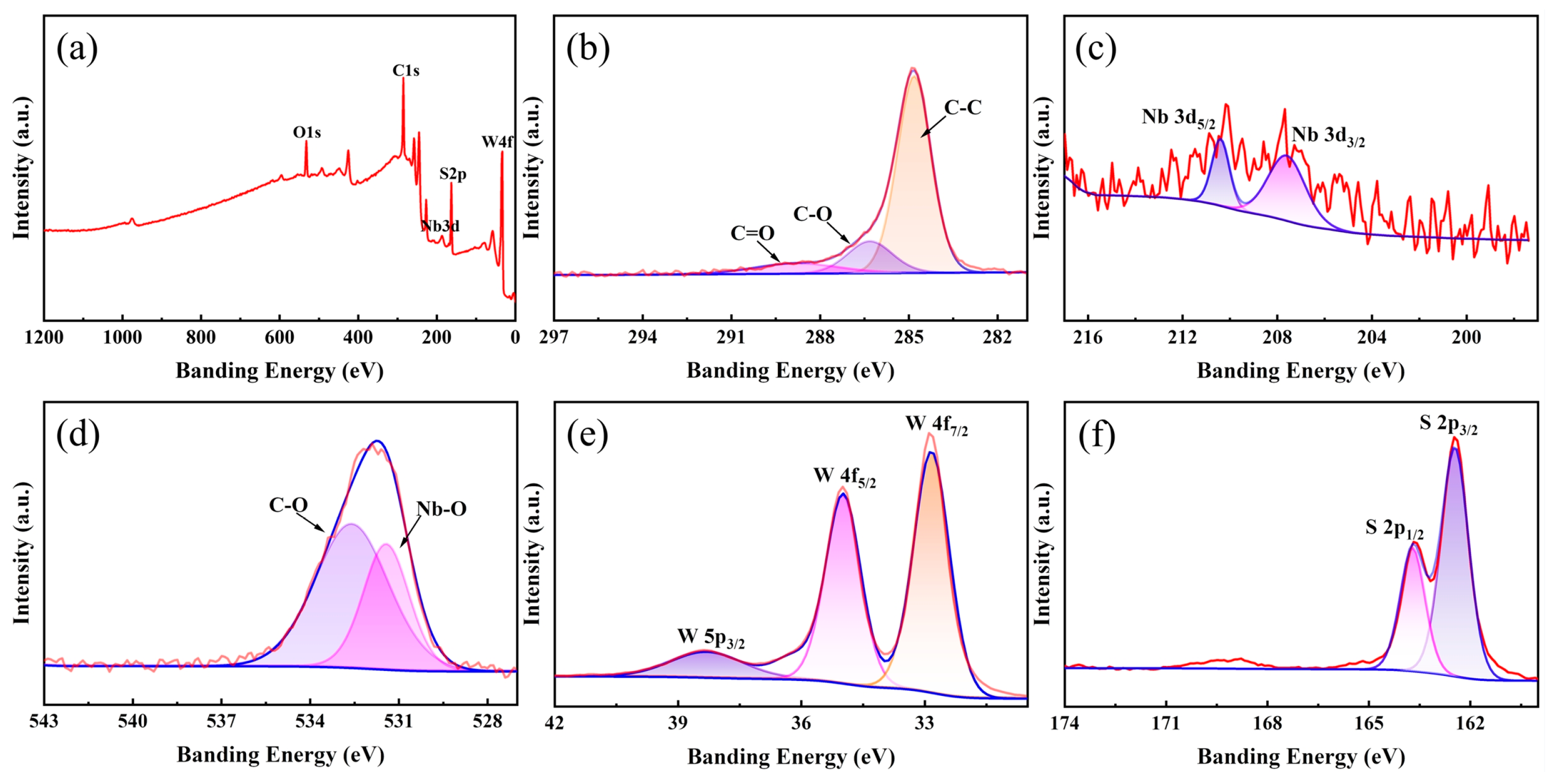
To comprehend the phase composition and valence state of elements, X-ray photoelectron spectroscopy (XPS) tests were conducted on Nb2O5@WS2@C CNFs. Figure 3 illustrates typical XPS spectra. The comprehensive XPS survey clearly reveals the presence of C, Nb, O, W, and S elements (Figure 3a). Three peaks in the high-resolution spectrum of C 1s are located at about 284.8, 286.3, and 288.5 eV (Figure 3b), which derive from C-C, C-O, and C=O bonding, respectively. Meanwhile, the C-C peak was also used for the calibration of the entire spectrum. Figure 3c presents the deconvoluted spectra of Nb 3d orbitals, with two electronic signals located at 207.7 and 210.5 eV, attributed to Nb 3d3/2 and Nb 3d5/2 modes, respectively [33]. In the O1s spectrum, the fitted peaks located at 531.4 and 532.6 eV correspond to Nb-O and C-O bonds, respectively (Figure 3d). Then, in Figure 3e, the W 4f7/2 and W4f5/2 at 32.8 and 35 eV dominate the overall W signal, confirming the presence of W4+ in Nb2O5@WS2@C CNFs. The lower peak at 38.3 eV corresponds to W 5p3/2, indicating the presence of a small amount of W6+, which may be attributed to incompletely reacted WOx [29,34,35]. In addition, the S 2p spectrum (Figure 3f) exhibits characteristic peaks at 162.5 and 163.7 eV, corresponding to the S 2p3/2 and S 2p1/2 states, respectively. Clearly, characterization results from XRD and XPS confirm the successful preparation of the envisioned Nb2O5@WS2@C CNFs.
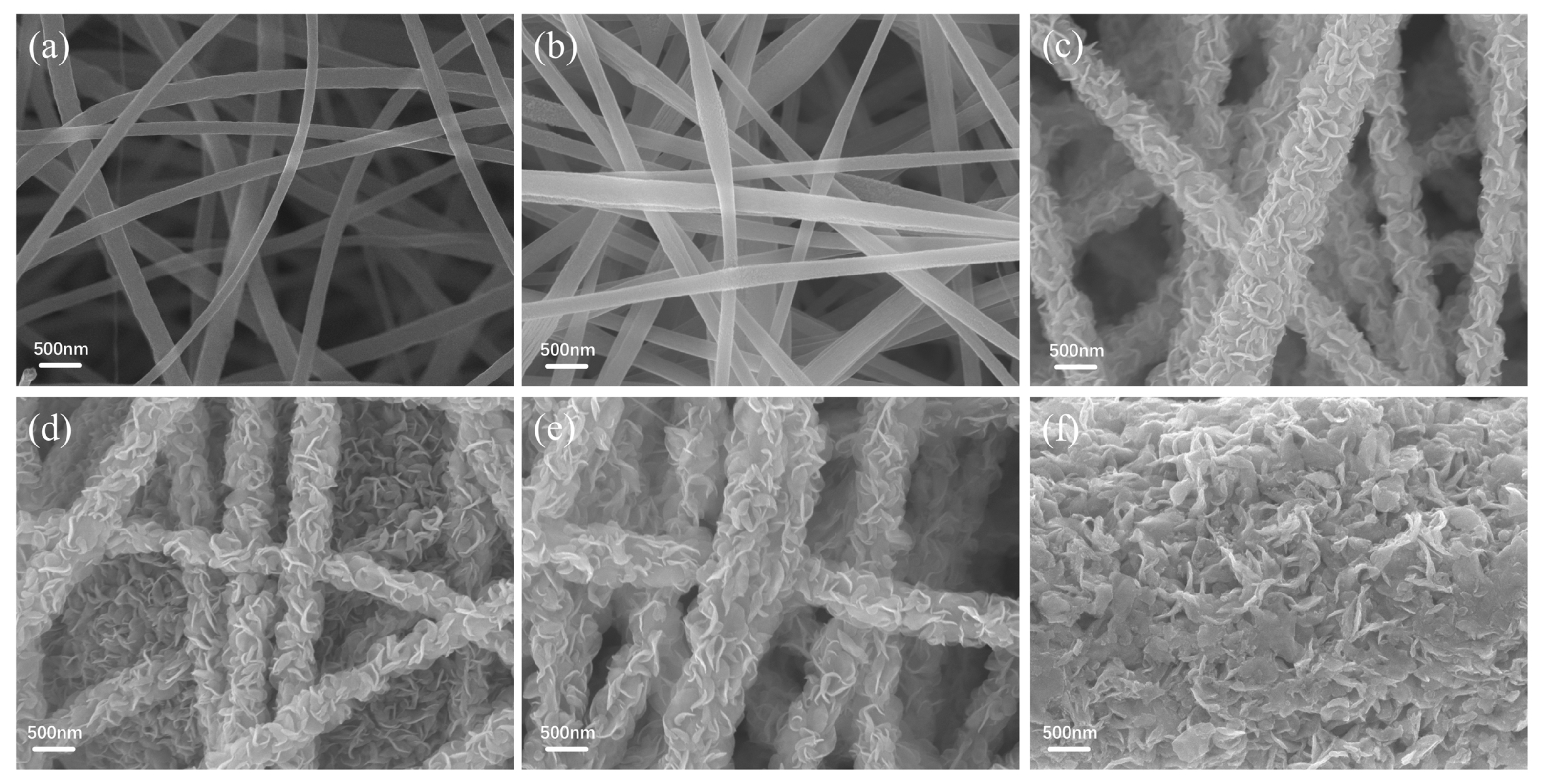
The microstructure and morphology of the samples were assessed through scanning electron microscopy (SEM) testing. As observed in Figure 4a,b, numerous fibers with a diameter of approximately 200 nm interweave with each other, forming a continuous mesh structure. In comparison to Nb2O5 CNFs and pure CNFs, the introduction of WS2 did not alter the network structure formed by interwoven fibers (Figure 4c). Compared to pure WS2 (Figure 4f), WS2 nanosheets are uniformly anchored on the surface of CNFs, forming a distinctive floral fiber structure. Evidently, this structure plays a significant role in improving the inhibition of WS2 aggregation. After the carbon coating of Nb2O5@WS2 CNFs, there is no apparent change in the overall microstructure of the material (Figure 4d).
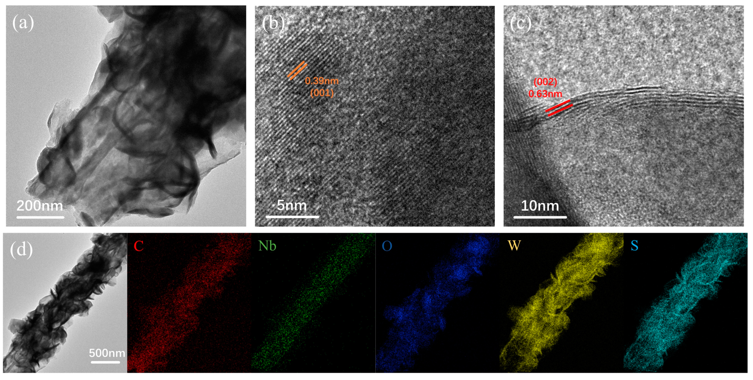
To further investigate the crystal structure and elemental distribution of the material, we conducted transmission electron microscopy (TEM) and energy dispersive X-ray spectroscopy (EDS) testing on Nb2O5@WS2@C CNFs. As depicted in Figure 5a, a distinct composite structure of CNF, Nb2O5, WS2, and C layers is revealed, consistent with the observations from SEM. By conducting high-resolution TEM (HRTEM) imaging on different regions, as shown in Figure 5b, it was found that the 0.39 nm lattice spacing within the CNFs corresponds well to the (001) crystal plane of Nb2O5. Meanwhile, as shown in Figure 5c, the evident 0.63 nm lattice stripes are associated with 2H-WS2. Additionally, EDS mapping scans were conducted using transmission electron microscopy, and the results, as shown in Figure 5d, reveal a uniform distribution of Nb within the nanofibers, while W and S are predominantly concentrated on the nanosheets.
We attempted a quantitative analysis of the Nb2O5@WS2@C CNFs. Initially, we investigated the carbon content of PAN, which was found to be approximately 50 wt%. Subsequently, we calculated and attempted to configure Nb2O5/C in a mass ratio of 1:1 for the preparation of Nb2O5 CNFs. The validation was conducted through thermogravimetric analysis (TGA) (Figure S2). On this basis, a quantitative analysis of the elements C, O, and S in Nb2O5@WS2@C CNFs was conducted using an organic elemental analyzer. The calculated mass ratios for the CNF, Nb2O5, WS2, and C layers were found to be 11%, 11%, 72%, and 6%, respectively.
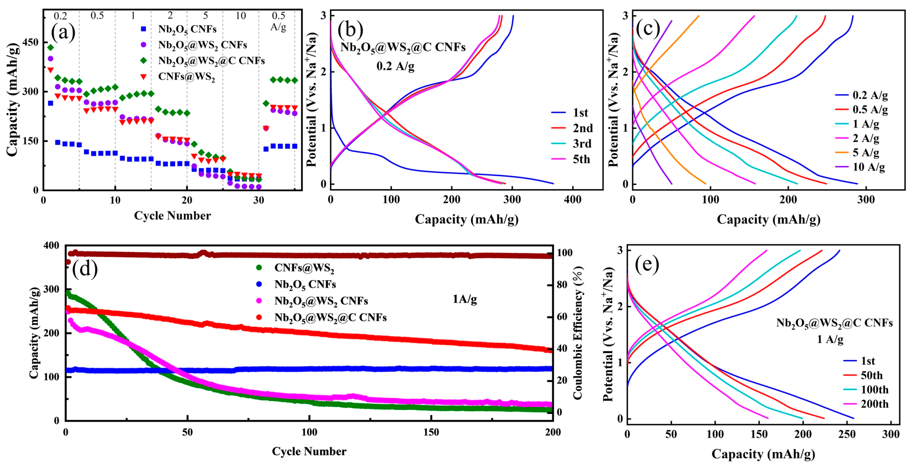
The above-prepared flexible carbon nanofibers paper was used to fabricate CR-2032 dual-electrode half-cells for electrochemical performance testing. Initially, rate performance tests were conducted on cells with different anodes at various current densities ranging from 0.2 to 10 A g−1 (Figure 6a). In the initial galvanostatic charge–discharge (GCD) cycles, all anode electrodes exhibit higher specific capacity and lower Coulombic efficiency compared to subsequent cycles. This is attributed to the formation of the solid electrolyte interface (SEI) film and the irreversible insertion of sodium ions. Compared to Nb2O5 CNFs, with the assistance of WS2, Nb2O5@WS2 CNFs exhibit an increase in specific capacity from 141 mA h g−1 to 305 mA h g−1 at a current density of 0.2 A g−1. Additionally, the incorporation of glucose-derived carbon results in a slight decrease in specific capacity for Nb2O5@WS2@C CNFs at low current density. However, as the current density gradually increases, Nb2O5@WS2@C CNFs exhibit a higher specific capacity. Evidently, the addition of the carbon layer enhances the rate performance of the anode electrode. CNFs@WS2 exhibits excellent capacity density at low current density; however, the poor rate performance of WS2 results in its specific capacity being lower than that of the Nb2O5@WS2@C CNF electrode when the current density exceeds 5 A g−1. Figure 6c illustrates the GCD curves of the Nb2O5@WS2@C CNF electrode at current densities of 0.2, 0.5, 1, 2, 5, and 10 A g−1, demonstrating impressive specific capacities of 289, 249, 211, 158, 94, and 50 mA h g−1, respectively. Moreover, after the Nb2O5@WS2@C CNF electrode undergoes high current density charge–discharge cycles, its capacity can recover to 253 mA h g−1 when the current density returns to 0.5 A g−1, demonstrating outstanding reversibility in sodium-ion storage.
To investigate the cyclic performance of the electrodes, we subjected different electrodes to repeated charge–discharge cycles at the same current density. Figure 6d illustrates the cyclic charge–discharge performance of four electrodes at a current density of 1 A g−1 after activation. Clearly, despite CNFs@ WS2 having a higher initial specific capacity (291 mA h g−1), there is rapid capacity degradation during the cyclic process due to volume expansion and structural damage. After 200 cycles, only 23 mA h g−1 remains, resulting in a mere 8% capacity retention. In comparison, Nb2O5 CNFs demonstrate excellent cyclic stability and capacity retention. After combining the two and a carbon layer coating, the Nb2O5@WS2@C CNF electrode combines the advantages of different materials, exhibiting an initial high specific capacity of up to 257 mA h g−1. Even after 200 cycles, it still maintains a capacity of 160 mA h g−1. However, even though the Nb2O5@WS2@C CNFs exhibit much better cycling stability than CNFs@WS2 and Nb2O5@WS2 CNFs, the electrochemical reactions occurring within them are not entirely reversible. This is particularly evident from the GCD curves of the 1st, 50th, 100th, and 200th cycles, where although the Coulombic efficiency of each charge–discharge cycle exceeds 99%, irreversible capacity decay is still observed. This is primarily attributed to electrode material degradation and irreversible sodium-ion insertion.
Cyclic voltammetry (CV) tests were conducted to investigate the sodium storage mechanism during the charge and discharge processes. The CV profiles of the initial four cycles of different electrodes at a scan rate of 0.5 mV s−1 in the voltage range of 0.01 to 3.00 V vs. Na+/Na are shown in Figure 7a. Similar to other reports, Nb2O5 CNFs show no distinct oxidation and reduction peaks, making them a typical intercalation-based sodium storage material [18,36]. In contrast, the CNFs@WS2 electrode exhibits two reduction peaks at 0.85 and 0.38 V. In this case, the weak reduction potential at around 0.85 V is attributed to the intercalation of Na+ ions into WS2 (WS2 + xNa+ + xe → NaxWS2). The main peak at approximately 0.38 V is caused by the conversion reaction between WS2 and Na+ ions, leading to the intercalation of metallic W into the amorphous Na2S matrix and the formation of the SEI film (NaxWS2 + (4 − x)Na+ + (4 − x)e → 2Na2S + W). The oxidation peaks at 2.0, 2.3, and 2.6 V correspond to the process of sodium deiodination (Na2S → S + 2Na+ + 2e; 2Na2S + W → WS2 + 4Na+ + 4e). In the second to fourth cycles, reduction peaks at 0.7, 1.3, and 2.0 V and oxidation peaks at 1.0, 1.8, and 2.6 V were observed, indicating the presence of multi-step redox reactions. For the Nb2O5@WS2@C CNF electrode, apart from the first cycle corresponding to the formation of the SEI film, the curves of the second to fourth cycles essentially overlap, demonstrating excellent reversibility in Na+ storage. Additionally, the positions of the oxidation–reduction peaks closely align with those of the CNFs@WS2 electrode, indicating that the primary redox reactions are associated with WS2.
To further investigate the electrochemical behavior, we conducted CV tests on the Nb2O5@WS2@C CNF electrode at a scan rate within the range of 0.3 to 3 mV s−1. The relationship between current (i) and scan rate (v) is shown as follows:
i = avb
log(i) = blog(v) + log(a)
Formula (2) is derived from Formula (1). The magnitude of the b value reflects the electrochemical behavior. When the b value approaches 0.5, it indicates diffusion-controlled behavior; when the b value approaches 1, it signifies that surface-controlled pseudocapacitive behavior predominates. As shown in Figure 7b, it is evident that the cathode and anode b values for the Nb2O5@WS2@C CNF electrode are 0.79 and 0.80, respectively. This suggests that the sodium-ion storage process is primarily governed by surface pseudocapacitive behavior.
The following formula can be used to quantitatively analyze the capacity ratio of diffusion/capacitive-controlled processes:
i(V) = k1v + k2v1/2
where k1v and k2v1/2 represent the capacitive-controlled and diffusion-controlled processes, respectively. The values of k1 and k2 can be calculated by plotting i/v1/2 versus v1/2 at a fixed V-value with various scan rates. By calculation, at a scanning rate of 1 mV s−1, it is determined that the electrode’s capacitive control ratio is 60%. Moreover, with the scanning rate increasing from 0.3 to 3 mV s−1, the capacitive control ratio rises from 53% to 78%. The prominence of the pseudocapacitive process is due to the presence of more redox reaction sites on the surface of the anode material, which confers fast reaction kinetics and thus superior rate performance. Apparently, the sodium storage mechanism based on adsorption–intercalation–conversion in the Nb2O5@WS2@C CNF electrode favors a fast charge/discharge process on the surface of the active material. The electrochemical impedance spectra (EIS) testing of the Nb2O5 CNFs, Nb2O5@WS2 CNFs and the Nb2O5@WS2@C CNF electrode was conducted to further investigate the reaction kinetics. In the Nyquist plot, a typical semicircle and a straight line can be observed. The semicircle in the high-frequency range typically corresponds to the resistance of Na+ through the SEI film and charge transfer resistance, while the straight line in the low-frequency region is associated with diffusion impedance. The equivalent circuit diagram and corresponding values are shown in Table S2. Clearly, the semicircular region of the Nb2O5 CNF electrode has a smaller diameter, indicating lower resistance. With the introduction of WS2, the resistance of the entire electrode rapidly increases, corresponding to the relatively poor kinetics of WS2. Finally, the addition of soft carbon enhances the conductivity of the electrode, and the reduction in the semicircle diameter implies lower resistance and faster charge transfer kinetics.
Certainly, combining materials with different sodium storage mechanisms is advantageous for fully exploiting the strengths of each material. In this context, PAN-derived carbon serves as the organic framework, providing the foundation for a free-standing material. Nb2O5, being a typical insertion-based sodium storage material, exhibits a relatively low theoretical specific capacity. However, during the charge and discharge processes, it shows minimal volume expansion, demonstrating excellent rate capability and cycling stability. Additionally, the uniform dispersion of Nb2O5 particles contributes to good flexibility. On the other hand, WS2 belongs to conversion-based materials, possessing a higher theoretical specific capacity. Yet, limitations such as poor rate kinetics and substantial volume expansion restrict its applications. The mesh-structure carbon nanofibers provide a framework for the growth of WS2, which can effectively prevent the aggregation of WS2 during charge–discharge cycling, and most importantly, the addition of the carbon layer will not only increase the conductivity of the material but also inhibit the volume expansion during cycling. Furthermore, the carbon layer prevents direct contact between WS2 and the electrolyte, thereby inhibiting the dissolution of WS2.

4. Conclusions

In summary, we have successfully designed and fabricated a flexible sodium storage anode electrode based on the synergistic effects of multiple mechanisms. Initially, Nb2O5 was uniformly dispersed within PAN-derived carbon nanofibers through electrospinning and subsequent annealing, providing a free-standing framework and flexibility for the composite electrode. Subsequently, a hydrothermal process successfully synthesized WS2 and a carbon layer on the carbon nanofibers, ultimately resulting in the unique three-dimensional flexible Nb2O5@WS2@C CNF electrode. After testing, sodium storage materials with different sodium storage mechanisms in the composite electrode are able to leverage their respective advantages, significantly improving the material’s capacity density, rate performance, and cycling stability. Additionally, since the entire electrode is composed of active materials without the need for current collectors, binders, and conductive additives, it is expected to help improve the energy density of the entire battery.

Supplementary Materials

The following supporting information can be downloaded at https://www.mdpi.com/article/10.3390/nano14070631/s1: Figure S1: Photograph of pure CNF films which were folded many times; Figure S2: TG curve of Nb2O5 CNFs; Figure S3: The GCD curve of Nb2O5 CNF, Nb2O5@WS2 CNF, Nb2O5@WS2@C CNF, and CNFs@WS2 electrodes at the current density of 0.5 A g−1; Figure S4: The CV profiles of initial four cycles for (a) Nb2O5 CNF, (b) Nb2O5@WS2 CNF, and (c) CNFs@WS2 electrodes at a scan rate of 0.5 mV s−1; Table S1: The results of elemental analysis; Table S2: The corresponding equivalent circuit and the calculated resistance values of the Nb2O5 CNFs, Nb2O5@WS2 CNFs, and Nb2O5@WS2@C CNFs.

Author Contributions

Investigation, methodology, data curation, Y.Z. and Z.F.; visualization, Y.T.; writing—original draft preparation, Y.Z.; writing—review and editing, Z.F. and Q.D.; conceptualization, Q.D.; supervision, Q.D. and L.Y.; funding acquisition, Q.D. and L.Y. All authors have read and agreed to the published version of the manuscript.

Funding

This work was financially supported by the National Natural Science Foundation of China (Grant Nos. 22109032 and 51802047), the Guangzhou Science and Technology Plan Project (No. 202201010327), the Talent Cultivation Project of Guangzhou University (No. RP2021038), the Guangzhou Basic Research Program, City & University (Institute) Joint Funding Project (No. SL2022A03J01003), the R & D Program of Joint Institute of Guangzhou University & Institute of Corrosion Science and Technology (Grant No. GI202104), the Key Discipline of Materials Science and Engineering, Bureau of Education of Guangzhou (Grant number: 202255464).

Data Availability Statement

Data are contained within the article and Supplementary Materials.

Conflicts of Interest

The authors declare no conflicts of interest.

References

  1. Zhu, S.; Dai, Y.; Li, J.; Ye, C.; Zhou, W.; Yu, R.; Liao, X.; Li, J.; Zhang, W.; Zong, W.; et al. Cathodic Zn underpotential deposition: An evitable degradation mechanism in aqueous zinc-ion batteries. Sci. Bull. 2022, 67, 1882–1889. [Google Scholar] [CrossRef] [PubMed]
  2. Zhu, Z.; Wang, M.; Meng, Y.; Lin, Z.; Cui, Y.; Chen, W. A High-Rate Lithium Manganese Oxide-Hydrogen Battery. Nano Lett. 2020, 20, 3278–3283. [Google Scholar] [CrossRef] [PubMed]
  3. Li, G. Regulating Mass Transport Behavior for High-Performance Lithium Metal Batteries and Fast-Charging Lithium-Ion Batteries. Adv. Energy Mater. 2021, 11, 2002891. [Google Scholar] [CrossRef]
  4. Wang, M.; Tang, Y. A Review on the Features and Progress of Dual-Ion Batteries. Adv. Energy Mater. 2018, 8, 1703320. [Google Scholar] [CrossRef]
  5. Liu, C.; Qiu, Y.; Liu, Y.; Xu, K.; Zhao, N.; Lao, C.; Shen, J.; Chen, Z. Novel 3D grid porous Li4Ti5O12 thick electrodes fabricated by 3D printing for high performance lithium-ion batteries. J. Adv. Ceram. 2022, 11, 295–307. [Google Scholar] [CrossRef]
  6. Schmuch, R.; Wagner, R.; Hörpel, G.; Placke, T.; Winter, M. Performance and cost of materials for lithium-based rechargeable automotive batteries. Nat. Energy 2018, 3, 267–278. [Google Scholar] [CrossRef]
  7. Li, M.; Lu, J.; Chen, Z.; Amine, K. 30 Years of Lithium-Ion Batteries. Adv. Mater. 2018, 30, 1800561. [Google Scholar] [CrossRef]
  8. Huang, J.; Wei, Z.; Liao, J.; Ni, W.; Wang, C.; Ma, J. Molybdenum and tungsten chalcogenides for lithium/sodium-ion batteries: Beyond MoS2. J. Energy Chem. 2019, 33, 100–124. [Google Scholar] [CrossRef]
  9. Luo, P.; Zheng, C.; He, J.; Tu, X.; Sun, W.; Pan, H.; Zhou, Y.; Rui, X.; Zhang, B.; Huang, K. Structural Engineering in Graphite-Based Metal-Ion Batteries. Adv. Funct. Mater. 2022, 32, 2107277. [Google Scholar] [CrossRef]
  10. Wang, L.; Yang, G.; Peng, S.; Wang, J.; Yan, W.; Ramakrishna, S. One-dimensional nanomaterials toward electrochemical sodium-ion storage applications via electrospinning. Energy Storage Mater. 2020, 25, 443–476. [Google Scholar] [CrossRef]
  11. Yu, F.; Huang, T.; Zhang, P.; Tao, Y.; Cui, F.-Z.; Xie, Q.; Yao, S.; Wang, F. Design and synthesis of electrode materials with both battery-type and capacitive charge storage. Energy Storage Mater. 2019, 22, 235–255. [Google Scholar] [CrossRef]
  12. Plewa, A.; Kulka, A.; Hanc, E.; Sun, J.; Nowak, M.; Redel, K.; Lu, L.; Molenda, J. Abnormal Phenomena of Multi-Way Sodium Storage in Selenide Electrode. Adv. Funct. Mater. 2021, 31, 2102406. [Google Scholar] [CrossRef]
  13. Liu, T.; He, Q.; Li, L.; Wang, H. Integrating antimony/amorphous vanadium oxide composite structure into electrospun carbon nanofibers for synergistically enhanced lithium/sodium-ion storage. J. Colloid Interface Sci. 2022, 624, 362–369. [Google Scholar] [CrossRef]
  14. Yang, L.; Yang, B.; Chen, X.; Wang, H.; Dang, J.; Liu, X. Bimetallic alloy SbSn nanodots filled in electrospun N-doped carbon fibers for high performance Na-ion battery anode. Electrochim. Acta 2021, 389, 138246. [Google Scholar] [CrossRef]
  15. Jia, G.; Chao, D.; Tiep, N.H.; Zhang, Z.; Fan, H.J. Intercalation Na-ion storage in two-dimensional MoS2-xSex and capacity enhancement by selenium substitution. Energy Storage Mater. 2018, 14, 136–142. [Google Scholar] [CrossRef]
  16. Kulka, A.; Hanc, A.; Walczak, K.; Płotek, J.; Sun, J.; Lu, L.; Borca, C.; Huthwelker, T. Direct evidence of an unanticipated crystalline phase responsible for the high performance of few-layered-MoS2 anodes for Na-ion batteries. Energy Storage Mater. 2022, 48, 314–324. [Google Scholar] [CrossRef]
  17. Subramanyan, K.; Akshay, M.; Lee, Y.-S.; Aravindan, V. Fabrication of Na-Ion Full-Cells using Carbon-Coated Na3V2(PO4)2O2F Cathode with Conversion Type CuO Nanoparticles from Spent Li-Ion Batteries. Small Methods 2022, 6, 2200257. [Google Scholar] [CrossRef] [PubMed]
  18. Deng, Q.; Chen, F.; Liu, S.; Bayaguud, A.; Feng, Y.; Zhang, Z.; Fu, Y.; Yu, Y.; Zhu, C. Advantageous Functional Integration of Adsorption-Intercalation-Conversion Hybrid Mechanisms in 3D Flexible Nb2O5@Hard Carbon@MoS2@Soft Carbon Fiber Paper Anodes for Ultrafast and Super-Stable Sodium Storage. Adv. Funct. Mater. 2020, 30, 1908665. [Google Scholar] [CrossRef]
  19. Li, H.; Zhang, Z.; Huang, X.; Lan, T.; Wei, M.; Ma, T. Metal–organic framework derived hierarchical porous TiO2 nanopills as a super stable anode for Na-ion batteries. J. Energy Chem. 2017, 26, 667–672. [Google Scholar] [CrossRef]
  20. Chu, Y.; Zhang, J.; Zhang, Y.; Li, Q.; Jia, Y.; Dong, X.; Xiao, J.; Tao, Y.; Yang, Q.-H. Reconfiguring Hard Carbons with Emerging Sodium-Ion Batteries: A Perspective. Adv. Mater. 2023, 35, 2212186. [Google Scholar] [CrossRef]
  21. Dou, X.; Hasa, I.; Saurel, D.; Vaalma, C.; Wu, L.; Buchholz, D.; Bresser, D.; Komaba, S.; Passerini, S. Hard carbons for sodium-ion batteries: Structure, analysis, sustainability, and electrochemistry. Mater. Today 2019, 23, 87–104. [Google Scholar] [CrossRef]
  22. She, L.; Zhang, F.; Jia, C.; Kang, L.; Li, Q.; He, X.; Sun, J.; Lei, Z.; Liu, Z.-H. Electrospun Nb2O5 nanorods/microporous multichannel carbon nanofiber film anode for Na+ ion capacitors with good performance. J. Colloid Interface Sci. 2020, 573, 1–10. [Google Scholar] [CrossRef] [PubMed]
  23. Chen, D.; Wang, J.-H.; Chou, T.-F.; Zhao, B.; El-Sayed, M.A.; Liu, M. Unraveling the Nature of Anomalously Fast Energy Storage in T-Nb2O5. J. Am. Chem. Soc. 2017, 139, 7071–7081. [Google Scholar] [CrossRef] [PubMed]
  24. Luo, D.; Ma, C.; Hou, J.; Zhang, Z.; Feng, R.; Yang, L.; Zhang, X.; Lu, H.; Liu, J.; Li, Y.; et al. Integrating Nanoreactor with O–Nb–C Heterointerface Design and Defects Engineering Toward High-Efficiency and Longevous Sodium Ion Battery. Adv. Energy Mater. 2022, 12, 2103716. [Google Scholar] [CrossRef]
  25. Liu, C.; Wang, B.; Song, Z.; Xiao, X.; Cao, Z.; Xiong, D.; Deng, W.; Hou, H.; Yang, Y.; Zou, G.; et al. Enabling Electron Delocalization by Conductor Heterostructure for Highly Reversible Sodium Storage. Adv. Funct. Mater. 2023, 2312905. [Google Scholar] [CrossRef]
  26. Rao, Y.; Wang, J.; Liang, P.; Zheng, H.; Wu, M.; Chen, J.; Shi, F.; Yan, K.; Liu, J.; Bian, K.; et al. Heterostructured WS2/MoS2@carbon hollow microspheres anchored on graphene for high-performance Li/Na storage. Chem. Eng. J. 2022, 443, 136080. [Google Scholar] [CrossRef]
  27. Dong, Z.; Wu, X.; Chen, M.; Chen, H.; Huang, K.-J.; Wang, L.; Xu, J. Self-supporting 1T-MoS2@WS2@CC composite materials for potential high-capacity sodium storage system. J. Colloid Interface Sci. 2023, 630, 426–435. [Google Scholar] [CrossRef]
  28. Xu, Y.; Wang, K.; Yao, Z.; Kang, J.; Lam, D.; Yang, D.; Ai, W.; Wolverton, C.; Hersam, M.C.; Huang, Y.; et al. Lithium/Sodium-Ion Batteries: In Situ, Atomic-Resolution Observation of Lithiation and Sodiation of WS2 Nanoflakes: Implications for Lithium-Ion and Sodium-Ion Batteries (Small 24/2021). Small 2021, 17, 2170120. [Google Scholar] [CrossRef]
  29. Wu, H.; Xu, N.; Jiang, Z.; Zheng, A.; Shi, Q.; Lv, R.; Ni, L.; Diao, G.; Chen, M. Space and interface confinement effect of necklace-box structural FeS2/WS2 carbon nanofibers to enhance Na+ storage performance and electrochemical kinetics. Chem. Eng. J. 2022, 427, 131002. [Google Scholar] [CrossRef]
  30. Li, X.; Sun, Y.; Xu, X.; Wang, Y.-X.; Chou, S.-L.; Cao, A.; Chen, L.; Dou, S.-X. Lotus rhizome-like S/N–C with embedded WS2 for superior sodium storage. J. Mater. Chem. A 2019, 7, 25932–25943. [Google Scholar] [CrossRef]
  31. Hou, H.; Qiu, X.; Wei, W.; Zhang, Y.; Ji, X. Carbon Anode Materials for Advanced Sodium-Ion Batteries. Adv. Energy Mater. 2017, 7, 1602898. [Google Scholar] [CrossRef]
  32. Yang, S.; Zhi, L.; Tang, K.; Feng, X.; Maier, J.; Müllen, K. Efficient Synthesis of Heteroatom (N or S)-Doped Graphene Based on Ultrathin Graphene Oxide-Porous Silica Sheets for Oxygen Reduction Reactions. Adv. Funct. Mater. 2012, 22, 3634–3640. [Google Scholar] [CrossRef]
  33. Liu, Y.; Ge, H.E.; Ren, Q.S.; Deng, H.W.; Li, Z.; Du, B.; Zhang, T. Improved corrosion resistance of TiAlCrNbMo alloy to lead-bismuth eutectic by pre-oxidation. J. Mater. Res. Technol. 2024, 28, 707–718. [Google Scholar] [CrossRef]
  34. Geng, S.; Zhou, T.; Jia, M.; Shen, X.; Gao, P.; Tian, S.; Zhou, P.; Liu, B.; Zhou, J.; Zhuo, S.; et al. Carbon-coated WS2 nanosheets supported on carbon nanofibers for high-rate potassium-ion capacitors. Energy Environ. Sci. 2021, 14, 3184–3193. [Google Scholar] [CrossRef]
  35. Sharma, P.; Minakshi, M.; Whale, J.; Jean-Fulcrand, A.; Garnweitner, G. Effect of the Anionic Counterpart: Molybdate vs. Tungstate in Energy Storage for Pseudo-Capacitor Applications. Nanomaterials 2021, 11, 580. [Google Scholar] [CrossRef]
  36. Li, Y.; Wang, H.; Wang, L.; Mao, Z.; Wang, R.; He, B.; Gong, Y.; Hu, X. Mesopore-Induced Ultrafast Na+-Storage in T-Nb2O5/Carbon Nanofiber Films toward Flexible High-Power Na-Ion Capacitors. Small 2019, 15, 1804539. [Google Scholar] [CrossRef]
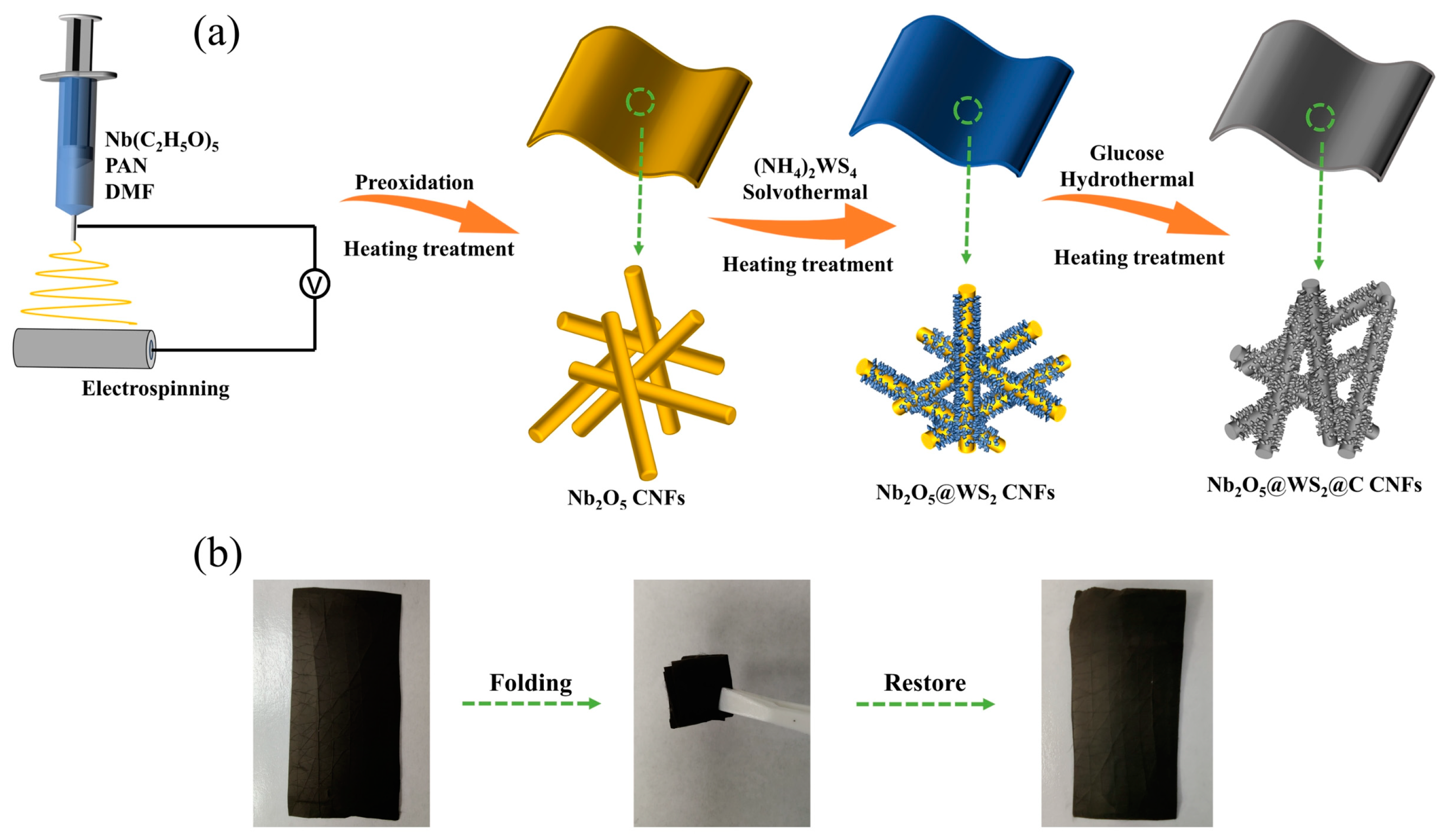
Figure 1. (a) Schematic illustration of the Nb2O5@WS2@C CNF film electrodes. (b) Photograph of Nb2O5@WS2@C CNF films which were folded many times.
Nanomaterials 14 00631 g001
Figure 2. (a) XRD patterns of as-prepared samples (the peaks at the black dots indicate incorporation of Orthorhombic Nb2O5). (b) Raman shift of Nb2O5 CNFs, Nb2O5@WS2 CNFs, and Nb2O5@WS2@C CNFs.
Nanomaterials 14 00631 g002
Figure 3. XPS spectra of the Nb2O5@WS2@C CNFs: (a) survey spectrum, (b) C 1s, (c) Nb 3d, (d) O 1s, (e) W 4f, and (f) S 2p.
Nanomaterials 14 00631 g003
Figure 4. SEM images of (a) pure CNFs, (b) Nb2O5 CNFs, (c) Nb2O5@WS2 CNFs, (d) Nb2O5@WS2@C CNFs, (e) CNFs@WS2, and (f) pure WS2.
Nanomaterials 14 00631 g004
Figure 5. (ac) TEM images of Nb2O5@WS2@C CNFs. (d) TEM image of Nb2O5@WS2@C CNFs with elemental mapping of C, Nb, O, W, and S.
Nanomaterials 14 00631 g005
Figure 6. (a) Rate performance of as-prepared samples at different current densities. The GCD curve of (b) 1st, 2nd, 3rd, and 5th cycles at the current density of 0.2 A g−1 and (c) different current density for the Nb2O5@WS2@C CNFs. (d) Cycling stability of as-prepared samples at a current density of 1 A g−1 with (e) the GCD curve of the 1st, 50th, 100th, and 200th cycles.
Nanomaterials 14 00631 g006
Figure 7. (a) The CV profiles of the initial four cycles for Nb2O5@WS2@C CNF electrode at a scan rate of 0.5 mV s−1. (b) The CV profiles of the Nb2O5@WS2@C CNF electrode at various scan rates from 0.3 to 3 mV s−1. (c) The relationship between peak currents and scan rates, (d) capacitive contribution curves at the scan rate of 1 mV s−1, and (e) normalized ratio of capacitive and diffusion at different scan rates, for Nb2O5@WS2@C CNF electrode. (f) EIS results of Nb2O5 CNFs, Nb2O5@WS2 CNFs, and Nb2O5@WS2@C CNFs.
Nanomaterials 14 00631 g007
Disclaimer/Publisher’s Note: The statements, opinions and data contained in all publications are solely those of the individual author(s) and contributor(s) and not of MDPI and/or the editor(s). MDPI and/or the editor(s) disclaim responsibility for any injury to people or property resulting from any ideas, methods, instructions or products referred to in the content.