
Enhancing the Green Synthesis of Glycerol Carbonate: Carboxylation of Glycerol with CO2 Catalyzed by Metal Nanoparticles Encapsulated in Cerium Metal–Organic Frameworks

Abstract
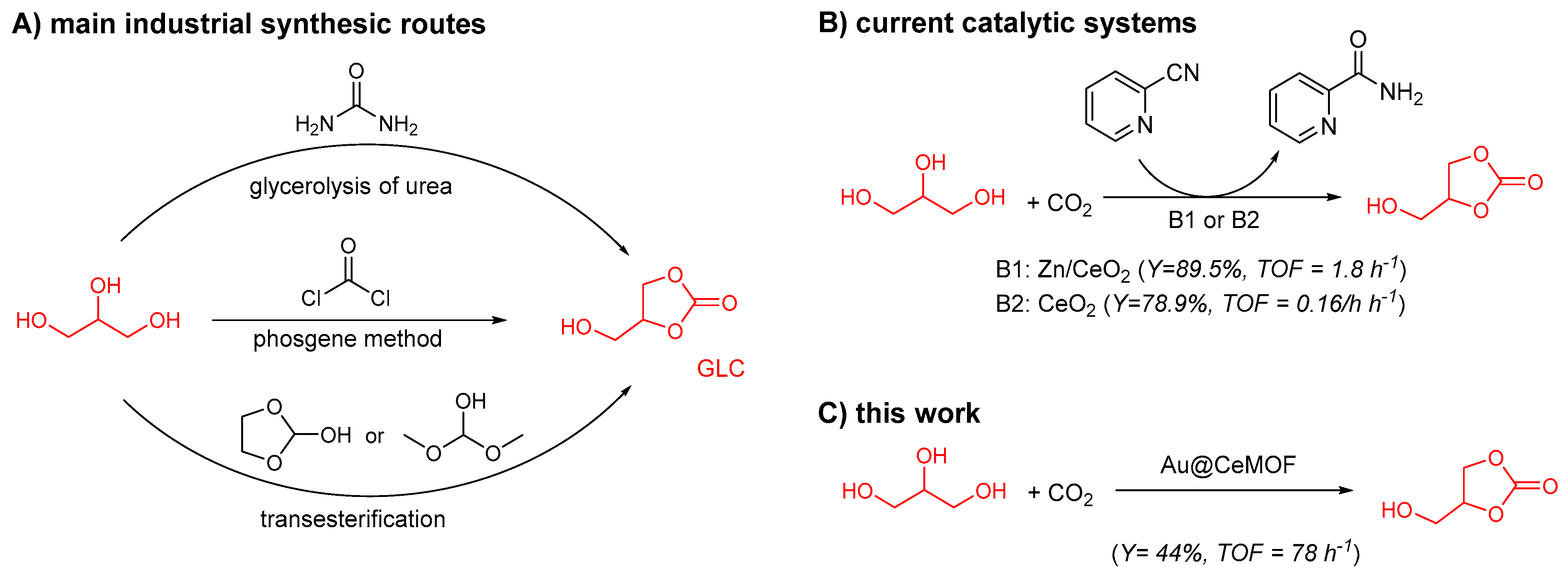
:1. Introduction
2. Materials and Methods
2.1. Chemicals and Instrumentation
2.2. Synthesis of Nanoparticles Au@PEI and Au@DBU
2.3. Pre-Synthesized MOF
2.4. Synthesis of Catalysts
- Method 1.
- Synthesis of catalysts using pre-synthesized MOF
- Method 2.
- Synthesis of 4%Au@DBU-MOF2
- Method 3.
- One-pot synthesis of the catalyst
2.5. Carboxylation of Glycerol with Carbon Dioxide Using the Catalysts
3. Results and Discussion
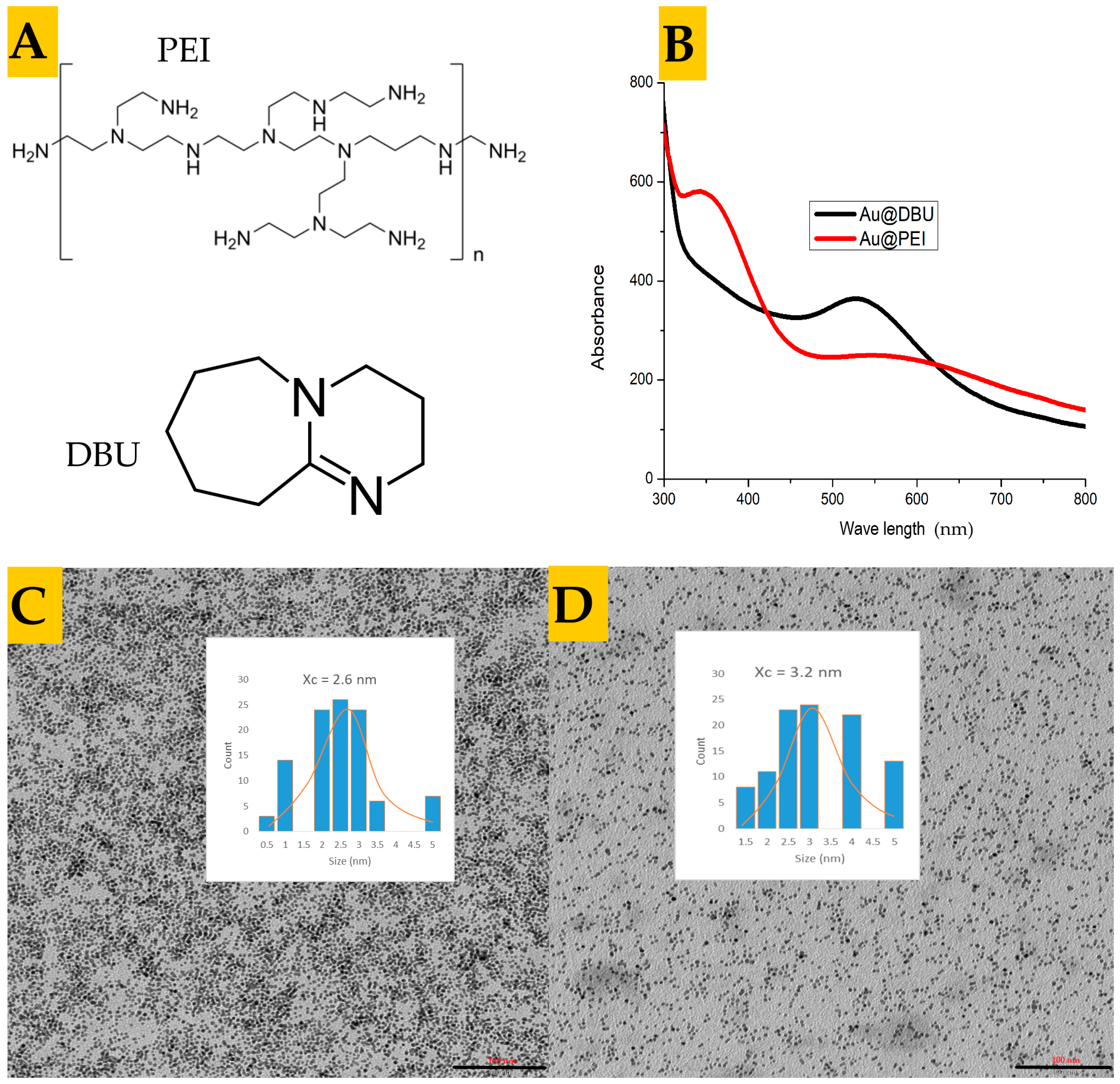
3.1. Synthesis and Characterization of the Nanoparticles
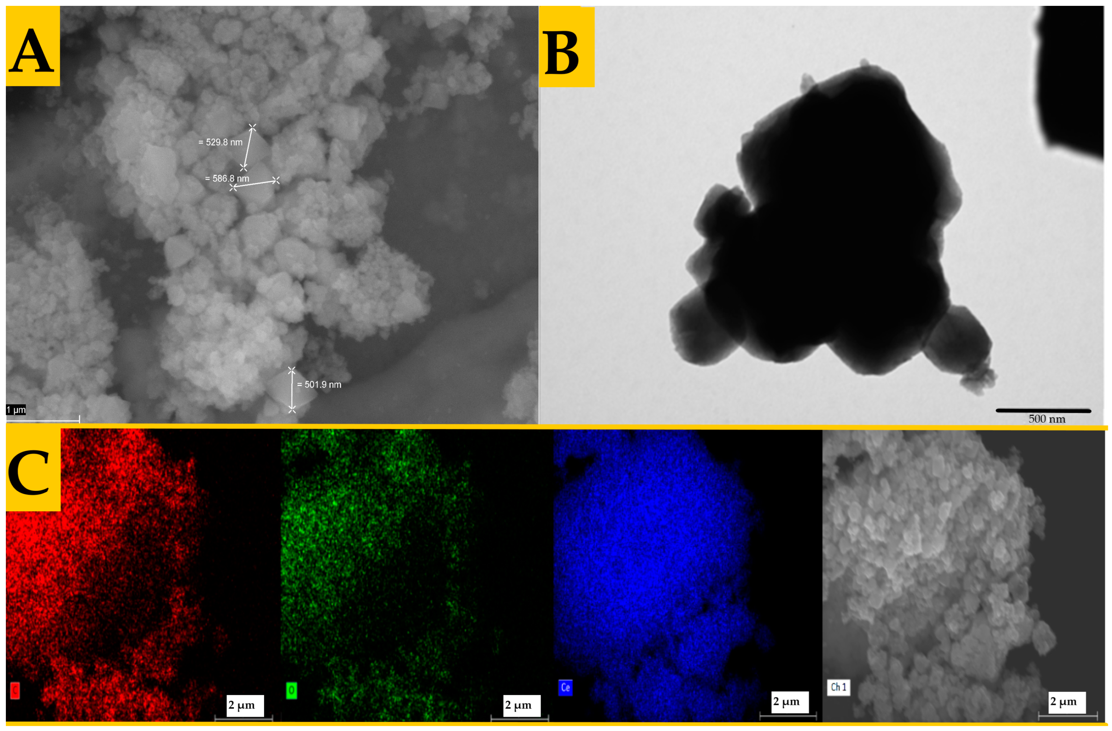
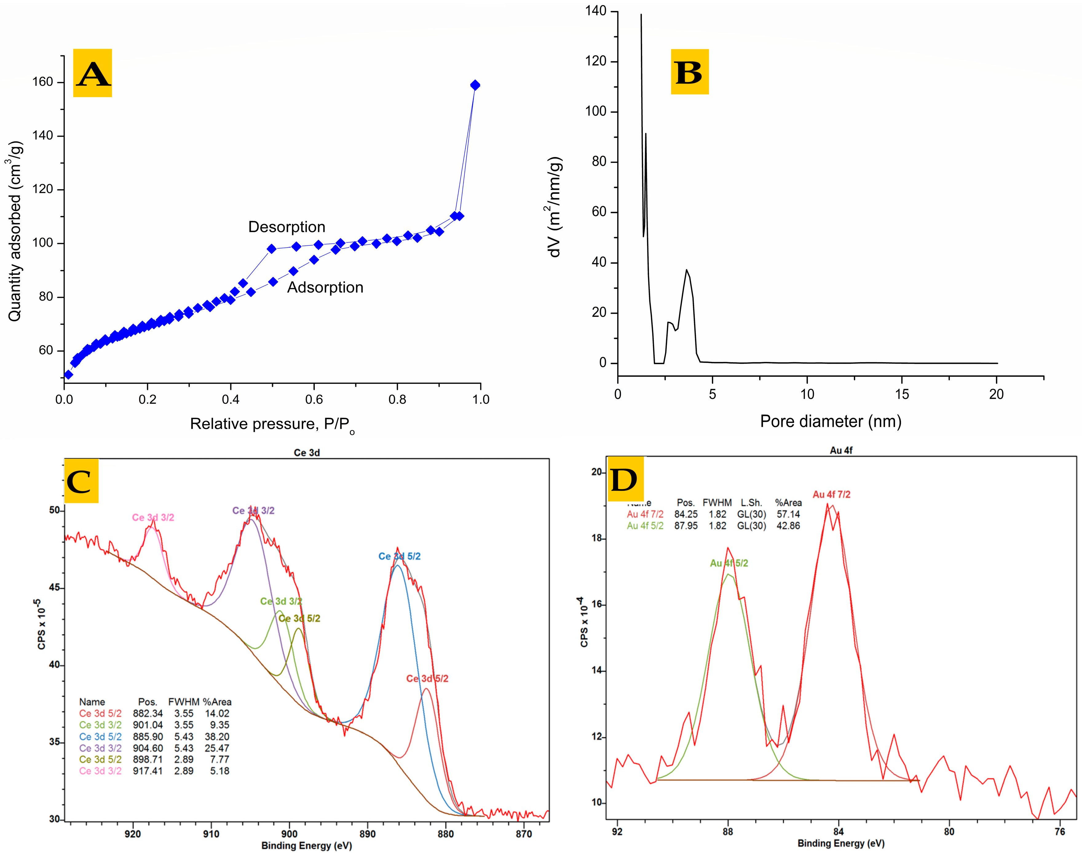
3.2. Analysis of Pre-Synthesized MOFs
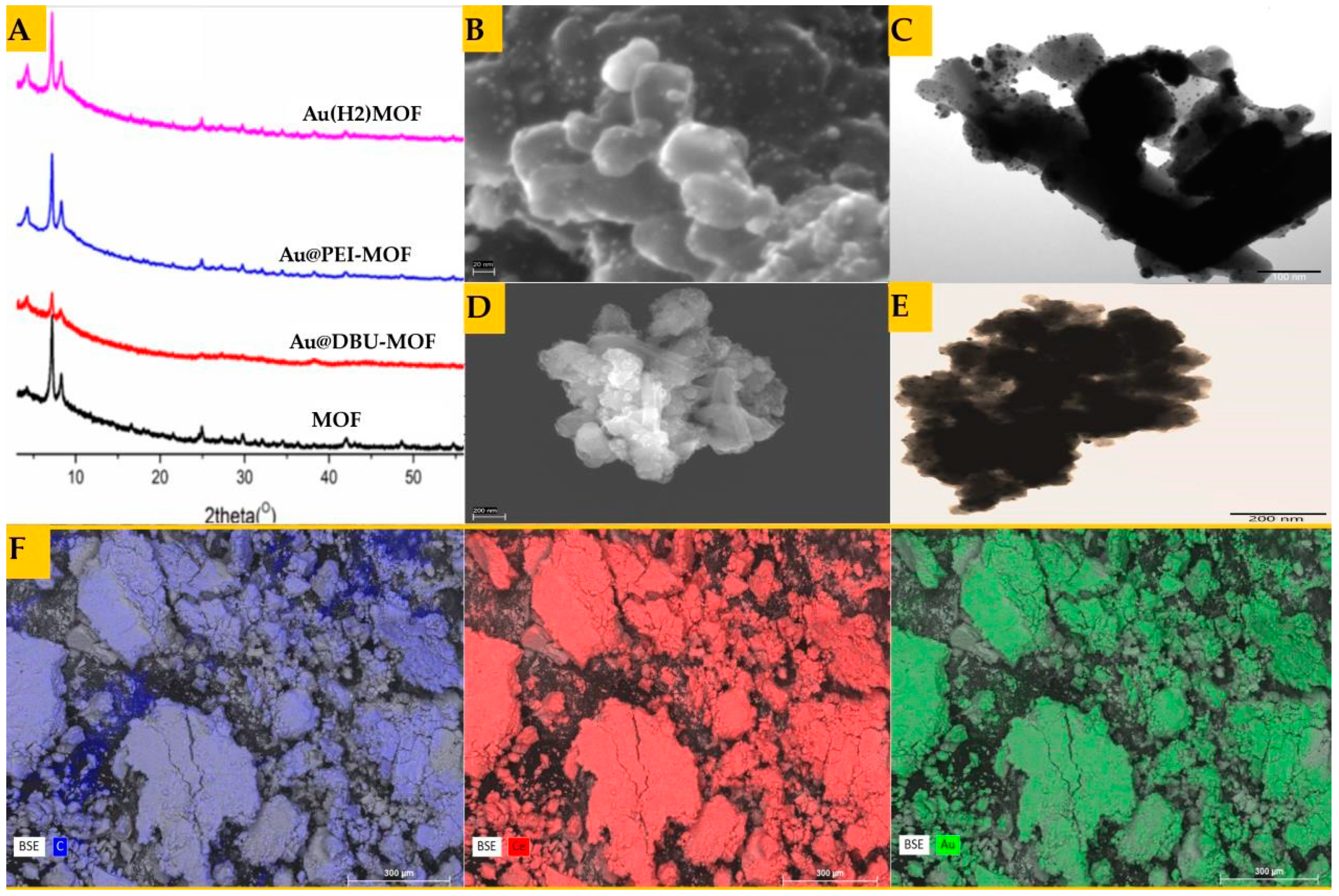
3.3. Synthesis and Characterization of the Catalysts
3.4. Catalytic Activity of Synthesized X%AuNPs@MOF
3.4.1. Effect of a Dehydrating Agent, Au Content, and Amount of Catalyst
3.4.2. Effect of the Reaction Time, Temperature, and Pressure
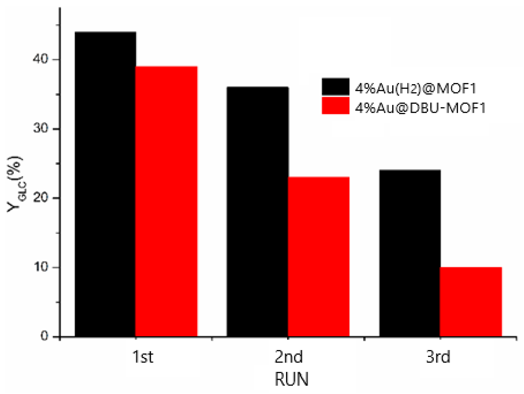
3.4.3. Regeneration and Efficiency of the Applied Catalysts
4. Conclusions
Supplementary Materials
Author Contributions
Funding
Data Availability Statement
Acknowledgments
Conflicts of Interest
References
- Monteiro, M.R.; Kugelmeier, C.L.; Pinheiro, R.S.; Batalha, M.O.; da Silva César, A. Glycerol from biodiesel production: Technological paths for sustainability. Renew. Sustain. Energy Rev. 2018, 88, 109–122. [Google Scholar] [CrossRef]
- Sonnati, M.O.; Amigoni, S.; de Givenchy, E.P.T.; Darmanin, T.; Choulet, O.; Guittard, F. Glycerol carbonate as a versatile building block for tomorrow: Synthesis, reactivity, properties and applications. Green Chem. 2013, 15, 283–306. [Google Scholar] [CrossRef]
- Christy, S.; Noschese, A.; Lomelí-Rodriguez, M.; Greeves, N.; Lopez-Sanchez, J.A. Recent progress in the synthesis and applications of glycerol carbonate. Curr. Opin. Green Sustain. Chem. 2018, 14, 99–107. [Google Scholar] [CrossRef]
- Lukato, S.; Kasozi, G.N.; Naziriwo, B.; Tebandeke, E. Glycerol carbonylation with CO2 to form glycerol carbonate: A review of recent developments and challenges. Curr. Res. Green Sustain. Chem. 2021, 4, 100199. [Google Scholar] [CrossRef]
- Tundo, P.; Musolino, M.; Aricò, F. The reactions of dimethyl carbonate and its derivatives. Green Chem. 2018, 20, 28–85. [Google Scholar] [CrossRef]
- Zhou, C.-H.C.; Beltramini, J.N.; Fan, Y.-X.; Lu, G.M. Chemoselective catalytic conversion of glycerol as a biorenewable source to valuable commodity chemicals. Chem. Soc. Rev. 2008, 37, 527–549. [Google Scholar] [CrossRef] [PubMed]
- Ochoa-Gómez, J.R.; Gómez-Jiménez-Aberasturi, O.; Maestro-Madurga, B.; Pesquera-Rodríguez, A.; Ramírez-López, C.; Lorenzo-Ibarreta, L.; Torrecilla-Soria, J.; Villarán-Velasco, M.C. Synthesis of glycerol carbonate from glycerol and dimethyl carbonate by transesterification: Catalyst screening and reaction optimization. Appl. Catal. A Gen. 2009, 366, 315–324. [Google Scholar] [CrossRef]
- Ochoa-Gómez, J.R.; Gómez-Jiménez-Aberasturi, O.; Ramirez-Lopez, C.; Belsué, M. A brief review on industrial alternatives for the manufacturing of glycerol carbonate, a green chemical. Org. Process Res. Dev. 2012, 16, 389–399. [Google Scholar] [CrossRef]
- Su, X.; Lin, W.; Cheng, H.; Zhang, C.; Wang, Y.; Yu, X.; Wu, Z.; Zhao, F. Metal-free catalytic conversion of CO2 and glycerol to glycerol carbonate. Green Chem. 2017, 19, 1775–1781. [Google Scholar] [CrossRef]
- Rozulan, N.; Halim, S.A.; Razali, N.; Lam, S.S. A review on direct carboxylation of glycerol waste to glycerol carbonate and its applications. Biomass Convers. Biorefinery 2022, 12, 4665–4682. [Google Scholar] [CrossRef]
- Procopio, D.; Di Gioia, M.L. An Overview of the Latest Advances in the Catalytic Synthesis of Glycerol Carbonate. Catalysts 2022, 12, 50. [Google Scholar] [CrossRef]
- Aresta, M.; Dibenedetto, A.; Nocito, F.; Pastore, C. A study on the carboxylation of glycerol to glycerol carbonate with carbon dioxide: The role of the catalyst, solvent and reaction conditions. J. Mol. Catal. A Chem. 2006, 257, 149–153. [Google Scholar] [CrossRef]
- George, J.; Patel, Y.; Pillai, S.M.; Munshi, P. Methanol assisted selective formation of 1, 2-glycerol carbonate from glycerol and carbon dioxide using nBu2SnO as a catalyst. J. Mol. Catal. A Chem. 2009, 304, 1–7. [Google Scholar] [CrossRef]
- Ozorio, L.P.; Pianzolli, R.; da Cruz Machado, L.; Miranda, J.L.; Turci, C.C.; Guerra, A.C.; Souza-Aguiar, E.F.; Mota, C.J. Metal-impregnated zeolite Y as efficient catalyst for the direct carbonation of glycerol with CO2. Appl. Catal. A Gen. 2015, 504, 187–191. [Google Scholar] [CrossRef]
- Ozorio, L.P.; Mota, C.J. Direct carbonation of glycerol with CO2 catalyzed by metal oxides. ChemPhysChem 2017, 18, 3260–3265. [Google Scholar] [CrossRef]
- Kulal, N.; Vetrivel, R.; Ganesh Krishna, N.S.; Shanbhag, G.V. Zn-Doped CeO2 Nanorods for Glycerol Carbonylation with CO2. ACS Appl. Nano Mater. 2021, 4, 4388–4397. [Google Scholar] [CrossRef]
- Liu, J.; Li, Y.; Zhang, J.; He, D. Glycerol carbonylation with CO2 to glycerol carbonate over CeO2 catalyst and the influence of CeO2 preparation methods and reaction parameters. Appl. Catal. A Gen. 2016, 513, 9–18. [Google Scholar] [CrossRef]
- Narayan, N.; Meiyazhagan, A.; Vajtai, R. Metal nanoparticles as green catalysts. Materials 2019, 12, 3602. [Google Scholar] [CrossRef]
- Dhakshinamoorthy, A.; Garcia, H. Catalysis by metal nanoparticles embedded on metal–organic frameworks. Chem. Soc. Rev. 2012, 41, 5262–5284. [Google Scholar] [CrossRef] [PubMed]
- Yang, Q.; Xu, Q.; Jiang, H.-L. Metal–organic frameworks meet metal nanoparticles: Synergistic effect for enhanced catalysis. Chem. Soc. Rev. 2017, 46, 4774–4808. [Google Scholar] [CrossRef] [PubMed]
- Nguyen, H.T.; Tran, Y.; Nguyen, H.N.; Nguyen, T.C.; Gándara, F.; Nguyen, P.T. A series of metal–organic frameworks for selective CO2 capture and catalytic oxidative carboxylation of olefins. Inorg. Chem. 2018, 57, 13772–13782. [Google Scholar] [CrossRef] [PubMed]
- Li, P.-Z.; Wang, X.-J.; Liu, J.; Lim, J.S.; Zou, R.; Zhao, Y. A Triazole-Containing Metal–Organic Framework as a Highly Effective and Substrate Size-Dependent Catalyst for CO2 Conversion. J. Am. Chem. Soc. 2016, 138, 2142–2145. [Google Scholar] [CrossRef] [PubMed]
- Mousavi, B.; Chaemchuen, S.; Phatanasri, S.; Chen, C.; Zeng, C.; Ganguly, R.; Zhuiykov, S.; Verpoort, F. Selective cyclodimerization of epichlorohydrin to dioxane derivatives over MOFs. Arab. J. Chem. 2020, 13, 1088–1093. [Google Scholar] [CrossRef]
- Farrusseng, D.; Tuel, A. Perspectives on zeolite-encapsulated metal nanoparticles and their applications in catalysis. New J. Chem. 2016, 40, 3933–3949. [Google Scholar] [CrossRef]
- Ndolomingo, M.J.; Bingwa, N.; Meijboom, R. Review of supported metal nanoparticles: Synthesis methodologies, advantages and application as catalysts. J. Mater. Sci. 2020, 55, 6195–6241. [Google Scholar] [CrossRef]
- Cao, A.; Lu, R.; Veser, G. Stabilizing metal nanoparticles for heterogeneous catalysis. Phys. Chem. Chem. Phys. 2010, 12, 13499–13510. [Google Scholar] [CrossRef] [PubMed]
- Zhu, Q.-L.; Xu, Q. Immobilization of ultrafine metal nanoparticles to high-surface-area materials and their catalytic applications. Chem 2016, 1, 220–245. [Google Scholar] [CrossRef]
- Zanon, A.; Verpoort, F. Metals@ ZIFs: Catalytic applications and size selective catalysis. Coord. Chem. Rev. 2017, 353, 201–222. [Google Scholar] [CrossRef]
- Gao, C.; Lyu, F.; Yin, Y. Encapsulated metal nanoparticles for catalysis. Chem. Rev. 2020, 121, 834–881. [Google Scholar] [CrossRef] [PubMed]
- Lesiak, P.; Bednarska, K.; Lewandowski, W.; Wójcik, M.; Polakiewicz, S.; Bagiński, M.; Osuch, T.; Markowski, K.; Orzechowski, K.; Makowski, M.; et al. Self-Organized, One-Dimensional Periodic Structures in a Gold Nanoparticle-Doped Nematic Liquid Crystal Composite. ACS Nano 2019, 13, 10154–10160. [Google Scholar] [CrossRef]
- Du, Y.; Sheng, H.; Astruc, D.; Zhu, M. Atomically Precise Noble Metal Nanoclusters as Efficient Catalysts: A Bridge between Structure and Properties. Chem. Rev. 2020, 120, 526–622. [Google Scholar] [CrossRef] [PubMed]
- Kehoe, A.B.; Scanlon, D.O.; Watson, G.W. Role of lattice distortions in the oxygen storage capacity of divalently doped CeO2. Chem. Mater. 2011, 23, 4464–4468. [Google Scholar] [CrossRef]
- Misch, L.M.; Kurzman, J.A.; Derk, A.R.; Kim, Y.-I.; Seshadri, R.; Metiu, H.; McFarland, E.W.; Stucky, G.D. C–H bond activation by Pd-substituted CeO2: Substituted ions versus reduced species. Chem. Mater. 2011, 23, 5432–5439. [Google Scholar] [CrossRef]
- Tao, Y.; Li, Z.; Ju, E.; Ren, J.; Qu, X. Polycations-functionalized water-soluble gold nanoclusters: A potential platform for simultaneous enhanced gene delivery and cell imaging. Nanoscale 2013, 5, 6154–6160. [Google Scholar] [CrossRef] [PubMed]
- Howarth, A.J.; Peters, A.W.; Vermeulen, N.A.; Wang, T.C.; Hupp, J.T.; Farha, O.K. Best Practices for the Synthesis, Activation, and Characterization of Metal–Organic Frameworks. Chem. Mater. 2017, 29, 26–39. [Google Scholar] [CrossRef]
- Aijaz, A.; Karkamkar, A.; Choi, Y.J.; Tsumori, N.; Rönnebro, E.; Autrey, T.; Shioyama, H.; Xu, Q. Immobilizing highly catalytically active Pt nanoparticles inside the pores of metal–organic framework: A double solvents approach. J. Am. Chem. Soc. 2012, 134, 13926–13929. [Google Scholar] [CrossRef] [PubMed]
- Imperor-Clerc, M.; Bazin, D.; Appay, M.-D.; Beaunier, P.; Davidson, A. Crystallization of β-MnO2 Nanowires in the Pores of SBA-15 Silicas: In Situ Investigation Using Synchrotron Radiation. Chem. Mater. 2004, 16, 1813–1821. [Google Scholar] [CrossRef]
- Shichibu, Y.; Negishi, Y.; Tsunoyama, H.; Kanehara, M.; Teranishi, T.; Tsukuda, T. Extremely high stability of glutathionate-protected Au25 clusters against core etching. Small 2007, 3, 835–839. [Google Scholar] [CrossRef] [PubMed]
- Kawasaki, H.; Hamaguchi, K.; Osaka, I.; Arakawa, R. ph-Dependent Synthesis of Pepsin-Mediated Gold Nanoclusters with Blue Green and Red Fluorescent Emission. Adv. Funct. Mater. 2011, 21, 3508–3515. [Google Scholar] [CrossRef]
- Li, L.; Liu, W.; Chen, R.; Shang, S.; Zhang, X.; Wang, H.; Zhang, H.; Ye, B.; Xie, Y. Atom-Economical Synthesis of Dimethyl Carbonate from CO2: Engineering Reactive Frustrated Lewis Pairs on Ceria with Vacancy Clusters. Angew. Chem. Int. Ed. 2022, 61, e202214490. [Google Scholar] [CrossRef] [PubMed]
- Farrag, M. In situ preparation of palladium nanoclusters in cerium metal-organic frameworks Ce-MOF-808, Ce-UiO-66 and Ce-BTC as nanoreactors for room temperature Suzuki cross-coupling reaction. Microporous Mesoporous Mater. 2021, 312, 110783. [Google Scholar] [CrossRef]
- Sun, W.; Li, X.; Sun, C.; Huang, Z.; Xu, H.; Shen, W. Insights into the pyrolysis processes of Ce-MOFs for preparing highly active catalysts of toluene combustion. Catalysts 2019, 9, 682. [Google Scholar] [CrossRef]
- Cheng, X.Q.; Li, S.; Bao, H.; Yang, X.; Li, Z.; Zhang, Y.; Wang, K.; Ma, J.; Ullah, A.; Shao, L. Poly (sodium-p-styrenesulfonate)-grafted UiO-66 composite membranes boosting highly efficient molecular separation for environmental remediation. Adv. Compos. Hybrid Mater. 2021, 4, 562–573. [Google Scholar] [CrossRef]
- Stawowy, M.; Róziewicz, M.; Szczepańska, E.; Silvestre-Albero, J.; Zawadzki, M.; Musioł, M.; Łuzny, R.; Kaczmarczyk, J.; Trawczyński, J.; Łamacz, A. The impact of synthesis method on the properties and CO2 sorption capacity of UiO-66 (Ce). Catalysts 2019, 9, 309. [Google Scholar] [CrossRef]
- Lu, G.-P.; Li, X.; Zhong, L.; Li, S.; Chen, F. Ru@ UiO-66 (Ce) catalyzed acceptorless dehydrogenation of primary amines to nitriles: The roles of Lewis acid–base pairs in the reaction. Green Chem. 2019, 21, 5386–5393. [Google Scholar] [CrossRef]
- Cavka, J.H.; Jakobsen, S.; Olsbye, U.; Guillou, N.; Lamberti, C.; Bordiga, S.; Lillerud, K.P. A new zirconium inorganic building brick forming metal organic frameworks with exceptional stability. J. Am. Chem. Soc. 2008, 130, 13850–13851. [Google Scholar] [CrossRef] [PubMed]
- Caratelli, C.; Hajek, J.; Cirujano, F.G.; Waroquier, M.; i Xamena, F.X.L.; Van Speybroeck, V. Nature of active sites on UiO-66 and beneficial influence of water in the catalysis of Fischer esterification. J. Catal. 2017, 352, 401–414. [Google Scholar] [CrossRef]
- Atzori, C.; Lomachenko, K.A.; Øien-Ødegaard, S.; Lamberti, C.; Stock, N.; Barolo, C.; Bonino, F. Disclosing the Properties of a New Ce(III)-Based MOF: Ce2(NDC)3(DMF)2. Cryst. Growth Des. 2019, 19, 787–796. [Google Scholar] [CrossRef]
- He, J.; Xu, Y.; Wang, W.; Hu, B.; Wang, Z.; Yang, X.; Wang, Y.; Yang, L. Ce(III) nanocomposites by partial thermal decomposition of Ce-MOF for effective phosphate adsorption in a wide pH range. Chem. Eng. J. 2020, 379, 122431. [Google Scholar] [CrossRef]
- Bakuru, V.R.; Velaga, B.; Peela, N.R.; Kalidindi, S.B. Hybridization of Pd Nanoparticles with UiO-66(Hf) Metal-Organic Framework and the Effect of Nanostructure on the Catalytic Properties. Chem.—A Eur. J. 2018, 24, 15978–15982. [Google Scholar] [CrossRef]
- Zhai, Y.; Li, Y.; Hou, Q.; Zhang, Y.; Zhou, E.; Li, H.; Ai, S. Highly sensitive colorimetric detection and effective adsorption of phosphate based on MOF-808 (Zr/Ce). New J. Chem. 2022, 46, 15405–15413. [Google Scholar] [CrossRef]
- Cai, X.; Pan, J.; Tu, G.; Fu, Y.; Zhang, F.; Zhu, W. Pd/UiO-66(Hf): A highly efficient heterogeneous catalyst for the hydrogenation of 2,3,5-trimethylbenzoquinone. Catal. Commun. 2018, 113, 23–26. [Google Scholar] [CrossRef]
- Turner, S.; Lebedev, O.I.; Schröder, F.; Esken, D.; Fischer, R.A.; Tendeloo, G.V. Direct Imaging of Loaded Metal−Organic Framework Materials (Metal@MOF-5). Chem. Mater. 2008, 20, 5622–5627. [Google Scholar] [CrossRef]
- Zhang, J.; Cheng, N.; Ge, B. Characterization of metal-organic frameworks by transmission electron microscopy. Adv. Phys. X 2022, 7, 2046157. [Google Scholar] [CrossRef]
- Liu, L.; Zhang, D.; Zhu, Y.; Han, Y. Bulk and local structures of metal–organic frameworks unravelled by high-resolution electron microscopy. Commun. Chem. 2020, 3, 99. [Google Scholar] [CrossRef] [PubMed]
- Zhang, X.; Hou, F.; Yang, Y.; Wang, Y.; Liu, N.; Chen, D.; Yang, Y. A facile synthesis for cauliflower like CeO2 catalysts from Ce-BTC precursor and their catalytic performance for CO oxidation. Appl. Surf. Sci. 2017, 423, 771–779. [Google Scholar] [CrossRef]
- Thommes, M.; Kaneko, K.; Neimark, A.V.; Olivier, J.P.; Rodriguez-Reinoso, F.; Rouquerol, J.; Sing, K.S.W. Physisorption of gases, with special reference to the evaluation of surface area and pore size distribution (IUPAC Technical Report). Pure Appl. Chem. 2015, 87, 1051–1069. [Google Scholar] [CrossRef]
- Lee, Y.; He, G.; Akey, A.J.; Si, R.; Flytzani-Stephanopoulos, M.; Herman, I.P. Raman analysis of mode softening in nanoparticle CeO2− δ and Au-CeO2− δ during CO oxidation. J. Am. Chem. Soc. 2011, 133, 12952–12955. [Google Scholar] [CrossRef] [PubMed]
- Huang, P.; Wu, F.; Zhu, B.; Gao, X.; Zhu, H.; Yan, T.; Huang, W.; Wu, S.; Song, D. CeO2 nanorods and gold nanocrystals supported on CeO2 nanorods as catalyst. J. Phys. Chem. B 2005, 109, 19169–19174. [Google Scholar] [CrossRef] [PubMed]
- Xu, Q.; Kharas, K.C.; Datye, A. The preparation of highly dispersed Au/Al2O3 by aqueous impregnation. Catal. Lett. 2003, 85, 229–235. [Google Scholar] [CrossRef]
- Lopez-Sanchez, J.A.; Dimitratos, N.; Hammond, C.; Brett, G.L.; Kesavan, L.; White, S.; Miedziak, P.; Tiruvalam, R.; Jenkins, R.L.; Carley, A.F. Facile removal of stabilizer-ligands from supported gold nanoparticles. Nat. Chem. 2011, 3, 551–556. [Google Scholar] [CrossRef] [PubMed]
- Zhou, Z.; Kooi, S.; Flytzani-Stephanopoulos, M.; Saltsburg, H. The role of the interface in CO oxidation on Au/CeO2 multilayer nanotowers. Adv. Funct. Mater. 2008, 18, 2801–2807. [Google Scholar] [CrossRef]
- Camellone, M.F.; Fabris, S. Reaction mechanisms for the CO oxidation on Au/CeO2 catalysts: Activity of substitutional Au3+/Au+ cations and deactivation of supported Au+ adatoms. J. Am. Chem. Soc. 2009, 131, 10473–10483. [Google Scholar] [CrossRef] [PubMed]
- Abad, A.; Concepción, P.; Corma, A.; García, H. A Collaborative Effect between Gold and a Support Induces the Selective Oxidation of Alcohols. Angew. Chem. Int. Ed. 2005, 44, 4066–4069. [Google Scholar] [CrossRef]
- Crist, V.B. Handbooks of Monochromatic XPS Spectra: The Elements and Native Oxides; John Wiley & Sons: New York, NY, USA, 2000. [Google Scholar]
- Si, R.; Flytzani-Stephanopoulos, M. Shape and crystal-plane effects of nanoscale ceria on the activity of Au-CeO2 catalysts for the water–gas shift reaction. Angew. Chem. 2008, 120, 2926–2929. [Google Scholar] [CrossRef]
- Zhou, Z.; Flytzani-Stephanopoulos, M.; Saltsburg, H. Decoration with ceria nanoparticles activates inert gold island/film surfaces for the CO oxidation reaction. J. Catal. 2011, 280, 255–263. [Google Scholar] [CrossRef]
- Horváth, A.; Beck, A.; Stefler, G.r.; Benkó, T.; Sáfrán, G.R.; Varga, Z.; Gubicza, J.; Guczi, L. Silica-supported Au nanoparticles decorated by CeO2: Formation, morphology, and CO oxidation activity. J. Phys. Chem. C 2011, 115, 20388–20398. [Google Scholar] [CrossRef]
- Casaletto, M.P.; Longo, A.; Martorana, A.; Prestianni, A.; Venezia, A.M. XPS study of supported gold catalysts: The role of Au0 and Au+δ species as active sites. Surf. Interface Anal. 2006, 38, 215–218. [Google Scholar] [CrossRef]
- Li, H.; Jiao, X.; Li, L.; Zhao, N.; Xiao, F.; Wei, W.; Sun, Y.; Zhang, B. Synthesis of glycerol carbonate by direct carbonylation of glycerol with CO2 over solid catalysts derived from Zn/Al/La and Zn/Al/La/M (M = Li, Mg and Zr) hydrotalcites. Catal. Sci. Technol. 2015, 5, 989. [Google Scholar] [CrossRef]
- Shen, Q.; Yan, H.; Yuan, X.; Li, R.; Kong, D.; Zhang, W.; Zhang, H.; Liu, Y.; Chen, X.; Feng, X. Tailoring morphology of MgO catalyst for the enhanced coupling reaction of CO2 and glycerol to glycerol carbonate. Fuel 2023, 335, 126972. [Google Scholar] [CrossRef]
- Takeuchi, K.; Matsumoto, K.; Fukaya, N.; Sato, K.; Choi, J.-C. Synthesis of Glycerol Carbonate from Glycerol and CO2 Using CaO as a Dehydrating Agent. Asian J. Org. Chem. 2022, 11, E202200212. [Google Scholar] [CrossRef]
- Razali, N.; McGregor, J. Improving product yield in the direct carboxylation of glycerol with CO2 through the tailored selection of dehydrating agents. Catalysts 2021, 11, 138. [Google Scholar] [CrossRef]
- Tomishige, K.; Gu, Y.; Nakagawa, Y.; Tamura, M. Reaction of CO2 With Alcohols to Linear-, Cyclic-, and Poly-Carbonates Using CeO2-Based Catalysts. Front. Energy Res. 2020, 8, 117. [Google Scholar] [CrossRef]
- Somorjai, G.A.; Park, J.Y. Molecular Factors of Catalytic Selectivity. Angew. Chem. Int. Ed. 2008, 47, 9212–9228. [Google Scholar] [CrossRef] [PubMed]
- Zhang, M.; Liu, Q.; Long, H.; Sun, L.; Murayama, T.; Qi, C. Insights into Au nanoparticle size and chemical state of Au/ZSM-5 catalyst for catalytic cracking of n-octane to increase propylene production. J. Phys. Chem. C 2021, 125, 16013–16023. [Google Scholar] [CrossRef]
- Wang, S.; Wang, J.; Sun, P.; Xu, L.; Okoye, P.U.; Li, S.; Zhang, L.; Guo, A.; Zhang, J.; Zhang, A. Disposable baby diapers waste derived catalyst for synthesizing glycerol carbonate by the transesterification of glycerol with dimethyl carbonate. J. Clean. Prod. 2019, 211, 330–341. [Google Scholar] [CrossRef]
- Koranian, P.; Dalai, A.K.; Sammynaiken, R. Production of glycerol carbonate from glycerol and carbon dioxide using metal oxide catalysts. Chem. Eng. Sci. 2024, 286, 119687. [Google Scholar] [CrossRef]
- Sheldon, R.A. The E factor 25 years on: The rise of green chemistry and sustainability. Green Chem. 2017, 19, 18–43. [Google Scholar] [CrossRef]
- Constable, D.J.; Curzons, A.D.; Cunningham, V.L. Metrics to ‘green’chemistry—Which are the best? Green Chem. 2002, 4, 521–527. [Google Scholar] [CrossRef]
- Lim, Y.N.; Lee, C.; Jang, H.-Y. Metal-Free Synthesis of Cyclic and Acyclic Carbonates from CO2 and Alcohols. Eur. J. Org. Chem. 2014, 2014, 1823–1826. [Google Scholar] [CrossRef]
- Song, X.; Wu, Y.; Pan, D.; Zhang, J.; Xu, S.; Gao, L.; Wei, R.; Xiao, G. Functionalized DVB-based polymer catalysts for glycerol and CO2 catalytic conversion. J. CO2 Util. 2018, 28, 326–334. [Google Scholar] [CrossRef]
- Liu, H.; Li, Q.-Q.; Zhou, L.; Deng, B.; Pan, P.-H.; Zhao, S.-Y.; Liu, P.; Wang, Y.-Y.; Li, J.-L. Confinement of Organic Dyes in UiO-66-Type Metal–Organic Frameworks for the Enhanced Synthesis of [1,2,5]Thiadiazole[3,4-g]benzoimidazoles. J. Am. Chem. Soc. 2023, 145, 17588–17596. [Google Scholar] [CrossRef] [PubMed]
- Melillo, A.; Cabrero-Antonino, M.; Ferrer, B.; Dhakshinamoorthy, A.; Baldoví, H.G.; Navalón, S. MOF-on-MOF Composites with UiO-66-Based Materials as Photocatalysts for the Overall Water Splitting under Sunlight Irradiation. Energy Fuels 2023, 37, 5457–5468. [Google Scholar] [CrossRef]


| Run | Dehydrating Agent | CGL [%] | YGLC [%] |
|---|---|---|---|
| 1 b | MgCO3 | 49 | 32 |
| 2 | Acetonitrile c | 75 | 12 |
| 3 | Adiponitrile c | 63 | 30 |
| 4 | MgCO3 | 51 | 39 |
| 5 | - | trace | - |
| Run | Catalyst | Dehydrating Agent | CGL [%] | YGLC [%] |
|---|---|---|---|---|
| 1 | 4%Au@DBU-MOF1 | MgCO3 | 51 | 39 |
| 2 | 4%Au@DBU-MOF1 | Adiponitrile b | 63 | 30 |
| 3 | 4%Au@PEI-MOF1 | MgCO3 | 65 | 42 |
| 4 | 4%Au@PEI-MOF1 | Adiponitrile b | 70 | 37 |
| 5 | 4%Au(H2)@MOF1 | MgCO3 | 52 | 44 |
| 6 | MOF | MgCO3 | 14 c | 12 |
| 7 | 4%Cu@PEI-MOF1 | MgCO3 | 25 d | 17 |
| 8 | 4%Ag@ PEI-MOF1 | MgCO3 | 33 d | 26 |
| 9 | 4%Au@DBU-MOF2 | MgCO3 | 49 e | 40 |
| 10 | 4%Au@DBU-MOF3 | MgCO3 | 26 | 18 |
| 11 | 3%Au@DBU-MOF1 | MgCO3 | 41 | 28 |
| 12 | 8%Au@DBU-MOF1 | MgCO3 | 68 | 43 |
| 13 f | 4%Au(H2)@MOF1 | MgCO3 | 49 | 7.0 |
| 14 | - | MgCO3 | <1 | - |
| Run | Catalyst Amount [g] | CGL [%] | YGLC [%] |
|---|---|---|---|
| 1 | 0.01 | 34 | 22 |
| 2 | 0.05 | 51 | 39 |
| 3 | 0.10 | 58 | 41 |
| 4 | 0.15 | 66 | 44 |
| Run | t [h] | T [°C] | p [MPa] | CGL [%] | YGLC [%] |
|---|---|---|---|---|---|
| 1 | 13 | 150 | 5.0 | 86 | 38 |
| 2 | 13 | 150 | 3.5 | 76 | 42 |
| 3 | 13 | 150 | 2.5 | 64 | 33 |
| 4 | 13 | 150 | 1.5 | 51 | 39 |
| 5 | 25 | 150 | 0.5 | 39 | 24 |
| 6 | 18 | 150 | 1.5 | 53 | 38 |
| 7 | 15 | 150 | 1.5 | 52 | 40 |
| 8 | 13 | 150 | 1.5 | 51 | 39 |
| 9 | 9 | 150 | 1.5 | 32 | 24 |
| 10 | 6 | 150 | 1.5 | 23 | 16 |
| 11 | 3 | 150 | 1.5 | 13 | 5 |
| 12 | 13 | 170 | 1.5 | 67 | 29 |
| 13 | 13 | 160 | 1.5 | 60 | 34 |
| 14 | 13 | 150 | 1.5 | 51 | 39 |
| 15 | 13 | 140 | 1.5 | 36 | 24 |
| 16 | 13 | 120 | 1.5 | 22 | 7 |
Disclaimer/Publisher’s Note: The statements, opinions and data contained in all publications are solely those of the individual author(s) and contributor(s) and not of MDPI and/or the editor(s). MDPI and/or the editor(s) disclaim responsibility for any injury to people or property resulting from any ideas, methods, instructions or products referred to in the content. |
© 2024 by the authors. Licensee MDPI, Basel, Switzerland. This article is an open access article distributed under the terms and conditions of the Creative Commons Attribution (CC BY) license (https://creativecommons.org/licenses/by/4.0/).
Share and Cite
Lukato, S.; Wójcik, M.; Krogul-Sobczak, A.; Litwinienko, G. Enhancing the Green Synthesis of Glycerol Carbonate: Carboxylation of Glycerol with CO2 Catalyzed by Metal Nanoparticles Encapsulated in Cerium Metal–Organic Frameworks. Nanomaterials 2024, 14, 650. https://doi.org/10.3390/nano14080650
Lukato S, Wójcik M, Krogul-Sobczak A, Litwinienko G. Enhancing the Green Synthesis of Glycerol Carbonate: Carboxylation of Glycerol with CO2 Catalyzed by Metal Nanoparticles Encapsulated in Cerium Metal–Organic Frameworks. Nanomaterials. 2024; 14(8):650. https://doi.org/10.3390/nano14080650
Chicago/Turabian StyleLukato, Simon, Michał Wójcik, Agnieszka Krogul-Sobczak, and Grzegorz Litwinienko. 2024. "Enhancing the Green Synthesis of Glycerol Carbonate: Carboxylation of Glycerol with CO2 Catalyzed by Metal Nanoparticles Encapsulated in Cerium Metal–Organic Frameworks" Nanomaterials 14, no. 8: 650. https://doi.org/10.3390/nano14080650