The Effect of Acceptor Structure on Emission Color Tuning in Organic Semiconductors with D–π–A–π–D Structures


Abstract
:
1. Introduction
2. Materials and Methods
2.1. Synthesis
2.2. Electrochemistry
2.3. Photophysics
2.4. Devices
3. Results
3.1. Synthesis
3.2. Electrochemical Properties
3.3. Photophysical Properties
3.4. Device Fabrication
4. Conclusions
Supplementary Materials
Author Contributions
Funding
Conflicts of Interest
References
- Cheng, N.; Zhang, C.; Liu, Y. Tuning the electronic and optical properties of NDT-based conjugated polymers by adopting fused heterocycles as acceptor units: A theoretical study. J. Mol. Model. 2017, 23, 225. [Google Scholar] [CrossRef] [PubMed]
- Pandey, L.; Risko, C.; Norton, J.E.; Brédas, J.L. Donor Acceptor Copolymers of Relevance for Organic Photovoltaics: A Theoretical Investigation of the Impact of Chemical Structure Modifications on the Electronic and Optical Properties. Macromolecules 2012, 45, 6405–6414. [Google Scholar] [CrossRef]
- Zaugg, K.; Velasco, J.; Robins, K.A.; Lee, D.C. Understanding the Electronic Properties of Acceptor–Acceptor’–Acceptor Triads. ACS Omega 2019, 4, 5434–5441. [Google Scholar] [CrossRef]
- Mancilha, F.S.; DaSilveira Neto, B.A.; Lopes, A.S.; Moreira, P.F.; Quina, F.H.; Gon??alves, R.S.; Dupont, J. Are molecular 5,8-pi-extended quinoxaline derivatives good chromophores for photoluminescence applications? Eur. J. Org. Chem. 2006, 2006, 4924–4933. [Google Scholar] [CrossRef]
- Ata, I.; Popovic, D.; Lindén, M.; Mishra, A.; Bäuerle, P. The influence of the central acceptor unit on the optoelectronic properties and photovoltaic performance of A–D–A–D–A-type co-oligomers. Org. Chem. Front. 2017, 4, 755–766. [Google Scholar] [CrossRef]
- Wood, S.; Kim, J.H.; Wade, J.; Park, J.B.; Hwang, D.H.; Kim, J.S. Systematic control of heteroatoms in donor–acceptor copolymers and its effects on molecular conformation and photovoltaic performance. J. Mater. Chem. C 2016, 4, 7966–7978. [Google Scholar] [CrossRef]
- Blouin, N.; Michaud, A.; Gendron, D.; Wakim, S.; Blair, E.; Neagu-Plesu, R.; Belletête, M.; Durocher, G.; Tao, Y.; Leclerc, M. Toward a Rational Design of Poly(2,7-Carbazole) Derivatives for Solar Cells. J. Am. Chem. Soc. 2008, 130, 732–742. [Google Scholar] [CrossRef] [PubMed]
- Graf, A.; Murawski, C.; Zakharko, Y.; Zaumseil, J.; Gather, M.C. Infrared Organic Light-Emitting Diodes with Carbon Nanotube Emitters. Adv. Mater. 2018, 30, 1706711. [Google Scholar] [CrossRef]
- Qin, W.; Ding, D.; Liu, J.; Yuan, W.Z.; Hu, Y.; Liu, B.; Tang, B.Z. Biocompatible Nanoparticles with Aggregation-Induced Emission Characteristics as Far-Red/Near-Infrared Fluorescent Bioprobes for In Vitro and In Vivo Imaging Applications. Adv. Funct. Mater. 2012, 22, 771–779. [Google Scholar] [CrossRef]
- Kim, D.H.; D’Aléo, A.; Chen, X.K.; Sandanayaka, A.D.S.; Yao, D.; Zhao, L.; Komino, T.; Zaborova, E.; Canard, G.; Tsuchiya, Y.; et al. High-efficiency electroluminescence and amplified spontaneous emission from a thermally activated delayed fluorescent near-infrared emitter. Nat. Photonics 2018, 12, 98–104. [Google Scholar] [CrossRef]
- Luo, D.; Chen, Q.; Qiu, Y.; Zhang, M.; Liu, B. Device Engineering for All-Inorganic Perovskite Light-Emitting Diodes. Nanomaterials 2019, 9, 1007. [Google Scholar] [CrossRef]
- Fu, H.; Cheng, Y.M.; Chou, P.T.; Chi, Y. Feeling blue? Blue phosphors for OLEDs. Mater. Today 2011, 14, 472–479. [Google Scholar] [CrossRef]
- Li, J.; Yan, J.; Wen, D.; Khan, W.U.; Shi, J.; Wu, M.; Su, Q.; Tanner, P.A. Advanced red phosphors for white light-emitting diodes. J. Mater. Chem. C 2016, 4, 8611–8623. [Google Scholar] [CrossRef]
- Yersin, H. Highly Efficient OLEDs with Phosphorescent Materials; Wiley-VCH: Weinheim, Germany, 2007. [Google Scholar]
- Uoyama, H.; Goushi, K.; Shizu, K.; Nomura, H.; Adachi, C. Highly efficient organic light-emitting diodes from delayed fluorescence. Nature 2012, 492, 234–238. [Google Scholar] [CrossRef]
- Tao, Y.; Yuan, K.; Chen, T.; Xu, P.; Li, H.; Chen, R.; Zheng, C.; Zhang, L.; Huang, W. Thermally Activated Delayed Fluorescence Materials Towards the Breakthrough of Organoelectronics. Adv. Mater. 2014, 26, 7931–7958. [Google Scholar] [CrossRef]
- Zeng, W.; Lai, H.Y.; Lee, W.K.; Jiao, M.; Shiu, Y.J.; Zhong, C.; Gong, S.; Zhou, T.; Xie, G.; Sarma, M.; et al. Achieving Nearly 30% External Quantum Efficiency for Orange-Red Organic Light Emitting Diodes by Employing Thermally Activated Delayed Fluorescence Emitters Composed of 1,8-Naphthalimide-Acridine Hybrids. Adv. Mater. 2018, 30, 1704961. [Google Scholar] [CrossRef]
- Godumala, M.; Choi, S.; Cho, M.J.; Choi, D.H. Recent breakthroughs in thermally activated delayed fluorescence organic light emitting diodes containing non-doped emitting layers. J. Mater. Chem. C 2019, 7, 2172–2198. [Google Scholar] [CrossRef]
- Jeon, S.K.; Park, H.J.; Lee, J.Y. Highly Efficient Soluble Blue Delayed Fluorescent and Hyperfluorescent Organic Light-Emitting Diodes by Host Engineering. ACS Appl. Mater. Interfaces 2018, 10, 5700–5705. [Google Scholar] [CrossRef]
- Nakanotani, H.; Higuchi, T.; Furukawa, T.; Masui, K.; Morimoto, K.; Numata, M.; Tanaka, H.; Sagara, Y.; Yasuda, T.; Adachi, C. High-efficiency organic light-emitting diodes with fluorescent emitters. Nat. Commun. 2014, 5, 4016. [Google Scholar] [CrossRef] [Green Version]
- Yamanaka, T.; Nakanotani, H.; Hara, S.; Hirohata, T.; Adachi, C. Near-infrared organic light-emitting diodes for biosensing with high operating stability. Appl. Phys. Express 2017, 10, 074101. [Google Scholar] [CrossRef]
- Wang, S.; Yan, X.; Cheng, Z.; Zhang, H.; Liu, Y.; Wang, Y. Highly Efficient Near-Infrared Delayed Fluorescence Organic Light Emitting Diodes Using a Phenanthrene-Based Charge-Transfer Compound. Angew. Chem. Int. Ed. 2015, 54, 13068–13072. [Google Scholar] [CrossRef]
- Wang, C.; Li, X.L.; Gao, Y.; Wang, L.; Zhang, S.; Zhao, L.; Lu, P.; Yang, B.; Su, S.J.; Ma, Y. Efficient Near-Infrared (NIR) Organic Light-Emitting Diodes Based on Donor-Acceptor Architecture: An Improved Emissive State from Mixing to Hybridization. Adv. Opt. Mater. 2017, 5, 1700441. [Google Scholar] [CrossRef]
- Li, C.; Duan, R.; Liang, B.; Han, G.; Wang, S.; Ye, K.; Liu, Y.; Yi, Y.; Wang, Y. Deep-Red to Near-Infrared Thermally Activated Delayed Fluorescence in Organic Solid Films and Electroluminescent Devices. Angew. Chem. Int. Ed. 2017, 56, 11525–11529. [Google Scholar] [CrossRef]
- Zampetti, A.; Minotto, A.; Squeo, B.M.; Gregoriou, V.G.; Allard, S.; Scherf, U.; Chochos, C.L.; Cacialli, F. Highly Efficient Solid-State Near-infrared Organic Light-Emitting Diodes incorporating A-D-A Dyes based on α,β-unsubstituted “BODIPY” Moieties. Sci. Rep. 2017, 7, 1611. [Google Scholar] [CrossRef]
- Zampetti, A.; Minotto, A.; Cacialli, F. Near-Infrared (NIR) Organic Light-Emitting Diodes (OLEDs): Challenges and Opportunities. Adv. Funct. Mater. 2019, 1807623. [Google Scholar] [CrossRef]
- Wex, B.; Kaafarani, B.R. Perspective on carbazole-based organic compounds as emitters and hosts in TADF applications. J. Mater. Chem. C 2017, 5, 8622–8653. [Google Scholar] [CrossRef] [Green Version]
- Xu, J.; Ji, Q.; Kong, L.; Du, H.; Ju, X.; Zhao, J. Soluble Electrochromic Polymers Incorporating Benzoselenadiazole and Electron Donor Units (Carbazole or Fluorene): Synthesis and Electronic-Optical Properties. Polymers 2018, 10, 450. [Google Scholar] [CrossRef]
- Ledwon, P.; Thomson, N.; Angioni, E.; Findlay, N.J.; Skabara, P.J.; Domagala, W. The role of structural and electronic factors in shaping the ambipolar properties of donor–acceptor polymers of thiophene and benzothiadiazole. RSC Adv. 2015, 5, 77303–77315. [Google Scholar] [CrossRef]
- Yin, X.; Sun, H.; Zeng, W.; Xiang, Y.; Zhou, T.; Ma, D.; Yang, C. Manipulating the LUMO distribution of quinoxaline-containing architectures to design electron transport materials: Efficient blue phosphorescent organic light-emitting diodes. Org. Electron. 2016, 37, 439–447. [Google Scholar] [CrossRef]
- Liu, X.; He, R.; Shen, W.; Li, M. Molecular design of donor–acceptor conjugated copolymers based on C, Si and N-bridged dithiophene and thienopyrroledione derivatives units for organic solar cells. J. Power Sources 2014, 245, 217–223. [Google Scholar] [CrossRef]
- Takimiya, K.; Osaka, I.; Nakano, M. π-Building Blocks for Organic Electronics: Revaluation of “Inductive” and “Resonance” Effects of π-Electron Deficient Units. Chem. Mater. 2014, 26, 587–593. [Google Scholar] [CrossRef]
- Sandanayaka, A.S.D.; Matsushima, T.; Adachi, C. Degradation Mechanisms of Organic Light-Emitting Diodes Based on Thermally Activated Delayed Fluorescence Molecules. J. Phys. Chem. C 2015, 119, 23845–23851. [Google Scholar] [CrossRef]
- Wong, M.Y.; Zysman-Colman, E. Purely Organic Thermally Activated Delayed Fluorescence Materials for Organic Light-Emitting Diodes. Adv. Mater. 2017, 29, 1605444. [Google Scholar] [CrossRef]
- Sun, K.; Chu, D.; Cui, Y.; Tian, W.; Sun, Y.; Jiang, W. Near-infrared thermally activated delayed fluorescent dendrimers for the efficient non-doped solution-processed organic light-emitting diodes. Org. Electron. 2017, 48, 389–396. [Google Scholar] [CrossRef]
- Radosław, M.; Sebastian, S.; Suwiński Jerzy, W. Simple synthesis of non-symmetric 1,4-dialkoxybenzenes via 4-alkoxyphenols. Org. Commun. 2016, 9, 23–31. [Google Scholar]
- Shi, J.; Huang, M.; Xin, Y.; Chen, Z.; Gong, Q.; Xu, S.; Cao, S. Synthesis and characterization of a series of carbazole-based monolithic photorefractive molecules. Mater. Lett. 2005, 59, 2199–2203. [Google Scholar] [CrossRef]
- Yang, Z.; Zhao, N.; Sun, Y.; Miao, F.; Liu, Y.; Liu, X.; Zhang, Y.; Ai, W.; Song, G.; Shen, X.; et al. Highly selective red and green-emitting two-photon fluorescent probes for cysteine detection and their bio-imaging in living cells. Chem. Commun. 2012, 48, 3442. [Google Scholar] [CrossRef]
- Barpuzary, D.; Patra, A.S.; Vaghasiya, J.V.; Solanki, B.G.; Soni, S.S.; Qureshi, M. Highly Efficient One-Dimensional ZnO Nanowire-Based Dye-Sensitized Solar Cell Using a Metal-Free, D−π−A-Type, Carbazole Derivative with More than 5% Power Conversion. ACS Appl. Mater. Interfaces 2014, 6, 12629–12639. [Google Scholar] [CrossRef]
- Ledwon, P.; Zassowski, P.; Jarosz, T.; Lapkowski, M.; Wagner, P.; Cherpak, V.; Stakhira, P. A novel donor–acceptor carbazole and benzothiadiazole material for deep red and infrared emitting applications. J. Mater. Chem. C 2016, 4, 2219–2227. [Google Scholar] [CrossRef]
- Mee, S.P.H.; Lee, V.; Baldwin, J.E. Significant Enhancement of the Stille Reaction with a New Combination of Reagents—Copper(I) Iodide with Cesium Fluoride. Chem. Eur. J. 2005, 11, 3294–3308. [Google Scholar] [CrossRef]
- Branowska, D.; Olender, E.; Wysocki, W.; Karczmarzyk, Z.; Bancerz, I.; Ledwon, P.; Lapkowski, M.; Mirosław, B.; Urbańczyk-Lipkowska, Z.; Kalicki, P. Synthesis and electrochemical characterization of oligothiophenes with 1,2,4-triazine and 5,5′-bi-1,2,4-triazine as strong electron acceptor units. Electrochim. Acta 2016, 214, 19–30. [Google Scholar] [CrossRef]
- Drewniak, A.; Tomczyk, M.; Hanusek, L.; Mielanczyk, A.; Walczak, K.; Nitschke, P.; Hajduk, B.; Ledwon, P. The Effect of Aromatic Diimide Side Groups on the π-Conjugated Polymer Properties. Polymers 2018, 10, 487. [Google Scholar] [CrossRef]
- Djurovich, P.I.; Mayo, E.I.; Forrest, S.R.; Thompson, M.E. Measurement of the lowest unoccupied molecular orbital energies of molecular organic semiconductors. Org. Electron. 2009, 10, 515–520. [Google Scholar] [CrossRef]
- Cardona, C.M.; Li, W.; Kaifer, A.E.; Stockdale, D.; Bazan, G.C. Electrochemical considerations for determining absolute frontier orbital energy levels of conjugated polymers for solar cell applications. Adv. Mater. 2011, 23, 2367–2371. [Google Scholar] [CrossRef]
- Pluczyk, S.; Vasylieva, M.; Data, P. Using Cyclic Voltammetry, UV-Vis-NIR, and EPR Spectroelectrochemistry to Analyze Organic Compounds. J. Vis. Exp. 2018, 140, e56656. [Google Scholar] [CrossRef]
- Liu, X.; Sun, Y.; Hsu, B.B.Y.; Lorbach, A.; Qi, L.; Heeger, A.J.; Bazan, G.C. Design and Properties of Intermediate-Sized Narrow Band-Gap Conjugated Molecules Relevant to Solution-Processed Organic Solar Cells. J. Am. Chem. Soc. 2014, 136, 5697–5708. [Google Scholar] [CrossRef]
- Zhu, H.; Huang, W.; Huang, Y.; Yang, J.; Wang, W. Narrow band-gap donor–acceptor copolymers based on diketopyrrolopyrrole and diphenylethene: Synthesis, characterization and application in field effect transistor. Dyes Pigments 2016, 127, 37–44. [Google Scholar] [CrossRef]
- Bian, L.; Zhu, E.; Tang, J.; Tang, W.; Zhang, F. Recent progress in the design of narrow bandgap conjugated polymers for high-efficiency organic solar cells. Prog. Polym. Sci. 2012, 37, 1292–1331. [Google Scholar] [CrossRef]
- Cao, X.; Tong, J.; He, Z.; Zhang, M.; Zhang, X.; Ma, J.; Gao, P.; Li, J.; Zhang, P.; Wang, C.; et al. An extremely narrow band gap conjugated polymer for photovoltaic devices covering UV to near-infrared light. Dyes Pigments 2018, 158, 319–325. [Google Scholar] [CrossRef]
- İçli-Özkut, M.; İpek, H.; Karabay, B.; Cihaner, A.; Önal, A.M. Furan and benzochalcogenodiazole based multichromic polymers via a donor acceptor approach. Polym. Chem. 2013, 4, 2457. [Google Scholar] [CrossRef]
- Regis, E.; de Aguiar, L.O.; Tuzimoto, P.; Girotto, E.; Frizon, T.E.; Dal Bó, A.G.; Zapp, E.; Marra, R.; Gallardo, H.; Vieira, A.A. Effect of heteroatom exchange (S/Se) in the mesomorphism and physical properties of benzochalcogenodiazole-based liquid crystals. Dyes Pigments 2018, 157, 109–116. [Google Scholar] [CrossRef]
- Aguiar, L.; Regis, E.; Tuzimoto, P.; Girotto, E.; Bechtold, I.H.; Gallardo, H.; Vieira, A.A. Investigation of thermal and luminescent properties in 4,7-diphenylethynyl-2,1,3-benzothiadiazole systems. Liq. Cryst. 2018, 45, 49–58. [Google Scholar] [CrossRef]
- Kayi, H.; Elkamel, A. A theoretical investigation of 4,7-di(furan-2-yl)benzo[c][1,2,5]selenadiazole-based donor–acceptor type conjugated polymer. Comput. Theor. Chem. 2015, 1054, 38–45. [Google Scholar] [CrossRef]
- Li, H.; Guo, Y.; Lei, Y.; Gao, W.; Liu, M.; Chen, J.; Hu, Y.; Huang, X.; Wu, H. D-π-A benzo[c][1,2,5]selenadiazole-based derivatives via an ethynyl bridge: Photophysical properties, solvatochromism and applications as fluorescent sensors. Dyes Pigments 2015, 112, 105–115. [Google Scholar] [CrossRef]
- Karabay, L.C.; Karabay, B.; Karakoy, M.S.; Cihaner, A. Effect of furan, thiophene and selenophene donor groups on benzoselenadiazole based donor-acceptor-donor systems. J. Electroanal. Chem. 2016, 780, 84–89. [Google Scholar] [CrossRef]
- Simokaitiene, J.; Grazulevicius, J.V.; Jankauskas, V.; Rutkaite, R.; Sidaravicius, J. Synthesis and properties of glass-forming phenothiazine and carbazole adducts. Dyes Pigments 2008, 79, 40–47. [Google Scholar] [CrossRef]
- Kirkus, M.; Simokaitiene, J.; Grazulevicius, J.V.; Jankauskas, V. Phenyl, carbazolyl and fluorenyl-substituted derivatives of indolo[3,2-b]carbazole as hole-transporting glass forming materials. Synth. Met. 2010, 160, 750–755. [Google Scholar] [CrossRef]
- Chosrovian, H.; Rentsch, S.; Grebner, D.; Dahm, D.U.; Birckner, E.; Naarmann, H. Time-resolved fluorescence studies on thiophene oligomers in solution. Synth. Met. 1993, 60, 23–26. [Google Scholar] [CrossRef]
- Tsami, A.; Bünnagel, T.W.; Farrell, T.; Scharber, M.; Choulis, S.A.; Brabec, C.J.; Scherf, U. Alternating quinoxaline/oligothiophene copolymers—Synthesis and unexpected absorption properties. J. Mater. Chem. 2007, 17, 1353–1355. [Google Scholar] [CrossRef]
- Sanzone, A.; Calascibetta, A.; Ghiglietti, E.; Ceriani, C.; Mattioli, G.; Mattiello, S.; Sassi, M.; Beverina, L. Suzuki–Miyaura Micellar One-Pot Synthesis of Symmetrical and Unsymmetrical 4,7-Diaryl-5,6-difluoro-2,1,3-benzothiadiazole Luminescent Derivatives in Water and under Air. J. Org. Chem. 2018, 83, 15029–15042. [Google Scholar] [CrossRef]
- Jheng, J.F.; Lai, Y.Y.; Wu, J.S.; Chao, Y.H.; Wang, C.L.; Hsu, C.S. Influences of the Non-Covalent Interaction Strength on Reaching High Solid-State Order and Device Performance of a Low Bandgap Polymer with Axisymmetrical Structural Units. Adv. Mater. 2013, 25, 2445–2451. [Google Scholar] [CrossRef]
- Cihaner, A.; Algı, F. A Novel Neutral State Green Polymeric Electrochromic with Superior n and p-Doping Processes: Closer to Red-Blue-Green (RGB) Display Realization. Adv. Funct. Mater. 2008, 18, 3583–3589. [Google Scholar] [CrossRef]
- Wang, L.; Huang, W.; Li, R.; Gehrig, D.; Blom, P.W.M.; Landfester, K.; Zhang, K.A.I. Structural Design Principle of Small-Molecule Organic Semiconductors for Metal-Free, Visible-Light-Promoted Photocatalysis. Angew. Chem. Int. Ed. 2016, 55, 9783–9787. [Google Scholar] [CrossRef]
- Gibson, G.L.; McCormick, T.M.; Seferos, D.S. Atomistic Band Gap Engineering in Donor—Acceptor Polymers. J. Am. Chem. Soc. 2012, 134, 539–547. [Google Scholar] [CrossRef]
- Belfield, K.D.; Ren, X.; Van Stryland, E.W.; Hagan, D.J.; Dubikovsky, V.; Miesak, E.J. Near-IR Two-Photon Photoinitiated Polymerization Using a Fluorone/Amine Initiating System. J. Am. Chem. Soc. 2000, 122, 1217–1218. [Google Scholar] [CrossRef]
- De Boni, L.; Fonseca, R.D.; Cardoso, K.R.A.; Grova, I.; Akcelrud, L.; Correa, D.S.; Mendonça, C.R. Characterization of two and three-photon absorption of polyfluorene derivatives. J. Polym. Sci. Part B Polym. Phys. 2014, 52, 747–754. [Google Scholar] [CrossRef]
- Li, Y.; Li, X.L.; Chen, D.; Cai, X.; Xie, G.; He, Z.; Wu, Y.C.; Lien, A.; Cao, Y.; Su, S.J. Design Strategy of Blue and Yellow Thermally Activated Delayed Fluorescence Emitters and Their All-Fluorescence White OLEDs with External Quantum Efficiency beyond 20%. Adv. Funct. Mater. 2016, 26, 6904–6912. [Google Scholar] [CrossRef]
- Chapran, M.; Lytvyn, R.; Begel, C.; Wiosna-Salyga, G.; Ulanski, J.; Vasylieva, M.; Volyniuk, D.; Data, P.; Grazulevicius, J.V. High-triplet-level phthalimide based acceptors for exciplexes with multicolor emission. Dyes Pigments 2019, 162, 872–882. [Google Scholar] [CrossRef]
- Pander, P.; Gogoc, S.; Colella, M.; Data, P.; Dias, F.B. Thermally Activated Delayed Fluorescence in Polymer–Small-Molecule Exciplex Blends for Solution-Processed Organic Light-Emitting Diodes. ACS Appl. Mater. Interfaces 2018, 10, 28796–28802. [Google Scholar] [CrossRef]
- Porcu, P.; Vonlanthen, M.; González-Méndez, I.; Ruiu, A.; Rivera, E. Design of Novel Pyrene-Bodipy Dyads: Synthesis, Characterization, Optical Properties, and FRET Studies. Molecules 2018, 23, 2289. [Google Scholar] [CrossRef]


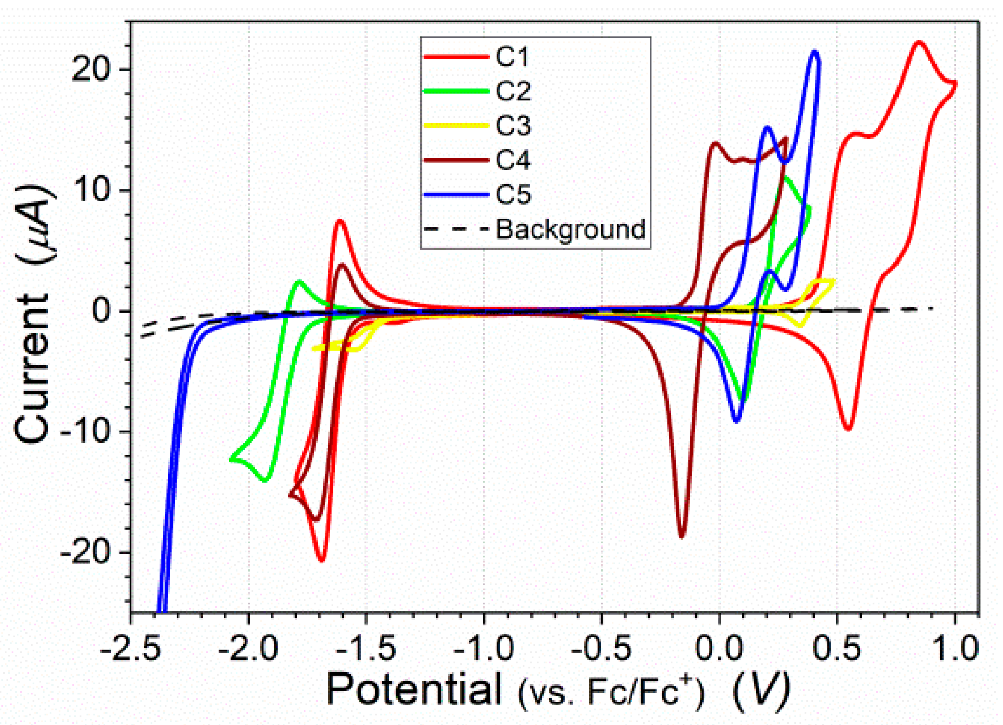
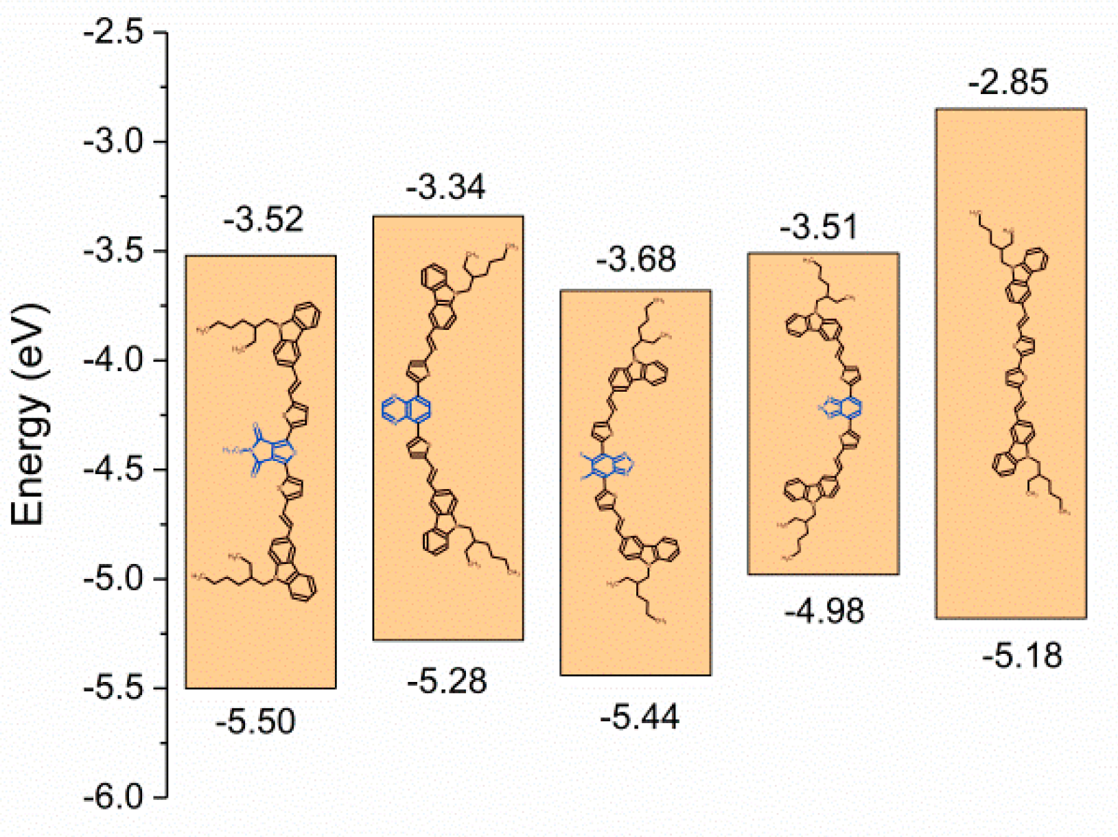
| 1Eox onset | 2Ered onset | 3IP | 4EA | 5EHOMO | 5ELUMO | 6ΔEgel | 7ΔEgopt | |
|---|---|---|---|---|---|---|---|---|
| Compound | [V] | [V] | [eV] | [eV] | [eV] | [eV] | [eV] | [eV] |
| C1 | 0.4 | −1.58 | 5.50 | 3.52 | −5.50 | −3.52 | 1.98 | 2.03 |
| C2 | 0.18 | −1.76 | 5.28 | 3.34 | −5.28 | −3.34 | 1.94 | 1.86 |
| C3 | 0.34 | −1.42 | 5.44 | 3.68 | −5.44 | −3.68 | 1.76 | 1.85 |
| C4 | −0.12 | −1.59 | 4.98 | 3.51 | −4.98 | −3.51 | 1.47 | 1.65 |
| C5 | 0.08 | −2.25 | 5.18 | 2.85 | −5.18 | −2.85 | 2.33 | 2.27 |
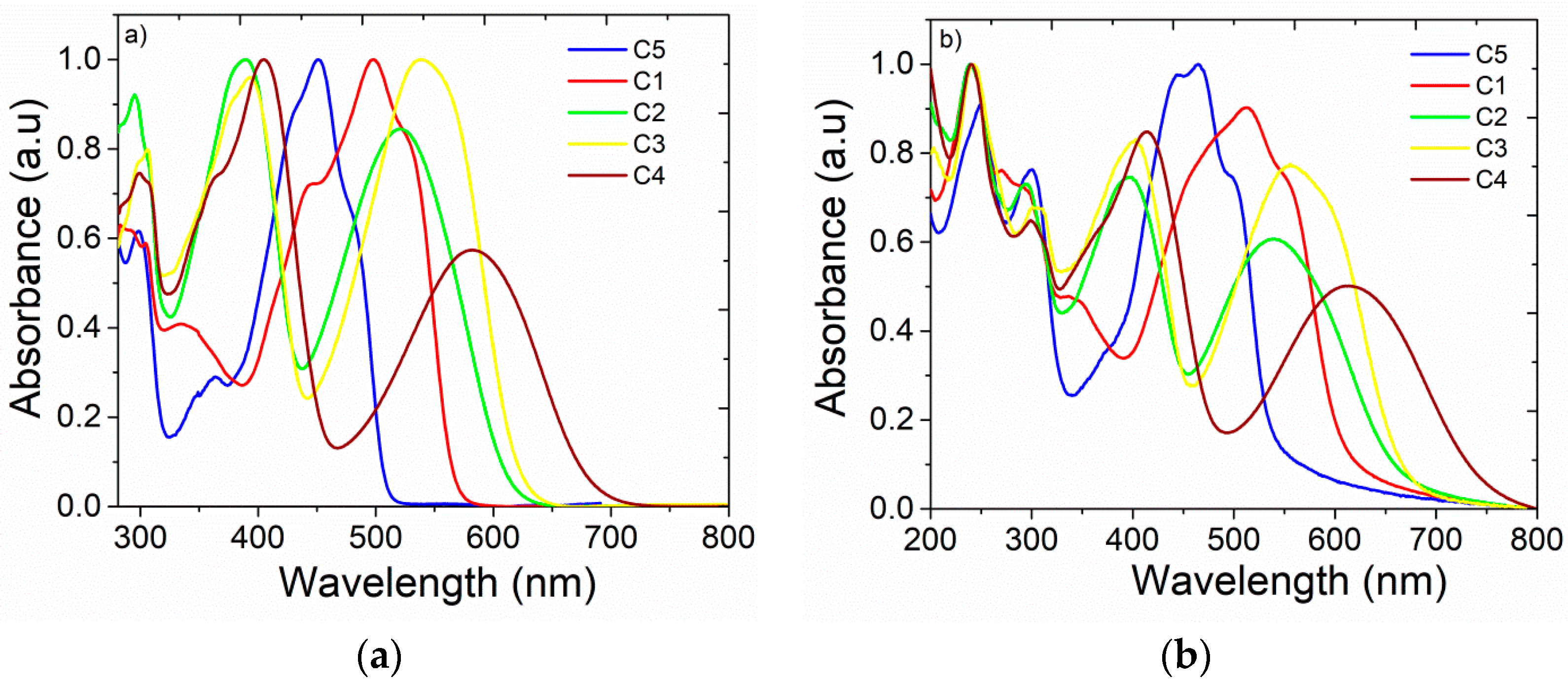
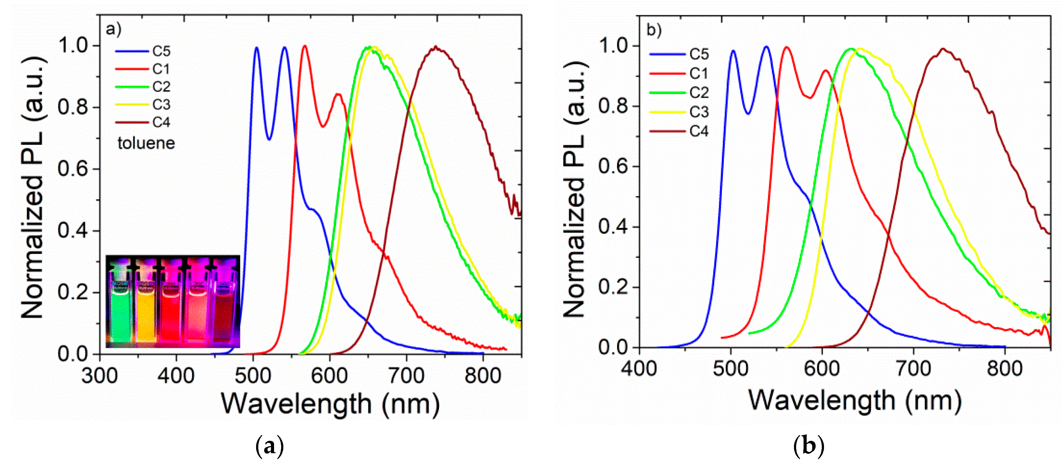
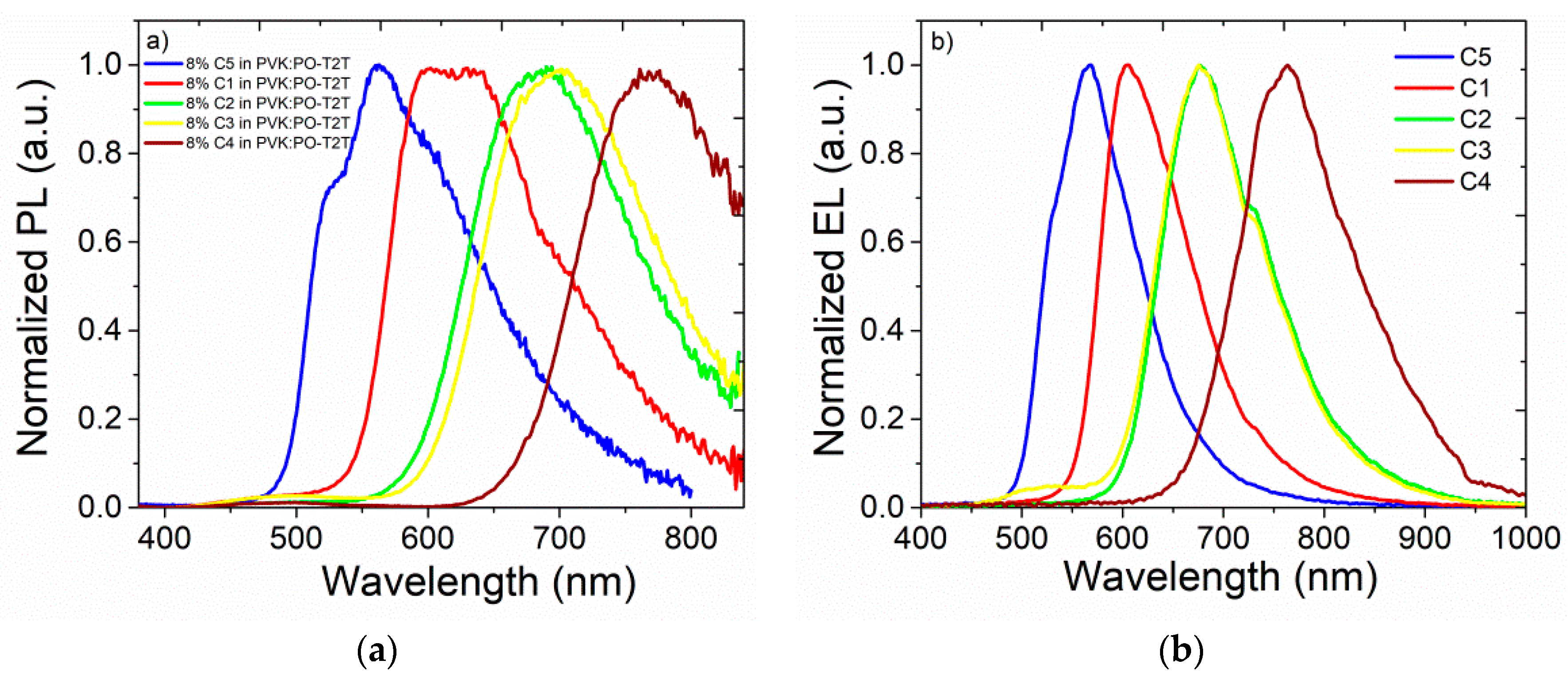
| λabs,tol [nm] | λabs,film [nm] | λPLzeon. [nm] | λPL,tol [nm] | λPL,chlor [nm] | λPL,THF [nm] | λPL,DCM [nm] | λPLfilm [nm] | |
|---|---|---|---|---|---|---|---|---|
| C5 | 451 | 465 | 502 | 505 | 509 | 506 | 510 | 528 |
| C1 | 498 | 514 | 560 | 568 | 582 | 585 | 592 | 685 |
| C2 | 520 | 540 | 633 | 651 | 670 | 675 | 679 | 725 |
| C3 | 539 | 558 | 640 | 660 | 695 | 701 | 707 | 740 |
| C4 | 583 | 614 | 733 | 740 | 770 | 776 | 782 | 835 |
| Mol | Solvent | ΦPL, % | τ ns | Radiative Rate Constant, (10 9 s−1) | Non-Radiative Rate Constant, (10 9 s−1) |
|---|---|---|---|---|---|
| C5 | TOL | 52 | 0.9 | 0.57 | 0.54 |
| CHL | 42 | 0.8 | 0.52 | 0.75 | |
| DCM | 50 | 0.9 | 0.56 | 0.56 | |
| THF | 52 | 0.9 | 0.58 | 0.53 | |
| C1 | TOL | 48 | 1.3 | 0.37 | 0.40 |
| CHL | 48 | 1.2 | 0.40 | 0.43 | |
| DCM | 42 | 1.1 | 0.38 | 0.52 | |
| THF | 41 | 1.1 | 0.37 | 0.54 | |
| C2 | TOL | 34 | 1.9 | 0.17 | 0.35 |
| CHL | 33 | 2.1 | 0.16 | 0.32 | |
| DCM | 31 | 1.9 | 0.16 | 0.36 | |
| THF | 32 | 2.1 | 0.15 | 0.32 | |
| C3 | TOL | 45 | 2.3 | 0.20 | 0.24 |
| CHL | 45 | 2.9 | 0.16 | 0.16 | |
| DCM | 38 | 2.5 | 0.15 | 0.25 | |
| THF | 39 | 2.7 | 0.14 | 0.23 | |
| C4 | TOL | 17 | 2.2 | 0.07 | 0.34 |
| CHL | 7 | 1.1 | 0.06 | 0.75 | |
| DCM | 4 | 1.0 | 0.04 | 0.95 | |
| THF | 7 | 1.5 | 0.047 | 0.62 |
© 2019 by the authors. Licensee MDPI, Basel, Switzerland. This article is an open access article distributed under the terms and conditions of the Creative Commons Attribution (CC BY) license (http://creativecommons.org/licenses/by/4.0/).
Share and Cite
Ledwon, P.; Wiosna-Salyga, G.; Chapran, M.; Motyka, R. The Effect of Acceptor Structure on Emission Color Tuning in Organic Semiconductors with D–π–A–π–D Structures. Nanomaterials 2019, 9, 1179. https://doi.org/10.3390/nano9081179
Ledwon P, Wiosna-Salyga G, Chapran M, Motyka R. The Effect of Acceptor Structure on Emission Color Tuning in Organic Semiconductors with D–π–A–π–D Structures. Nanomaterials. 2019; 9(8):1179. https://doi.org/10.3390/nano9081179
Chicago/Turabian StyleLedwon, Przemyslaw, Gabriela Wiosna-Salyga, Marian Chapran, and Radoslaw Motyka. 2019. "The Effect of Acceptor Structure on Emission Color Tuning in Organic Semiconductors with D–π–A–π–D Structures" Nanomaterials 9, no. 8: 1179. https://doi.org/10.3390/nano9081179