Recent Development of Corrosion Factors and Coating Applications in Biomass Firing Plants

College of Mechanical Engineering, Yangzhou University, Yangzhou 225127, China
*
Author to whom correspondence should be addressed.
Coatings 2020, 10(10), 1001; https://doi.org/10.3390/coatings10101001
Submission received: 18 September 2020
/
Revised: 10 October 2020
/
Accepted: 16 October 2020
/
Published: 19 October 2020
Abstract
:Due to global warming, biomass fuels are gradually being used to replace fossil fuels. However, high-temperature biomass corrosion is a crucial issue affecting its future application. In this article, different factors affecting boiler performance are summarized from various studies to guide the optimization of boiler parameters in practical applications, such as corrosive components and boiler temperatures. Meanwhile, different coating formation methods and materials are summarized to provide better protection strategies. The potential coating materials for future research are also discussed. The addition of other elements, such as Ti, Mo, and W, has the potential to accelerate the formation of oxide layers during high-temperature corrosion and directly slow down the corrosion rate. Future studies should focus on these elements containing materials.
1. Introduction
With the development of human society, fossil fuels have gradually become the main source of energy. Nowadays, 80% of the energy comes from the heat generated by burning coal and fuel [1]. The burning of fossil fuels results in a large amount of greenhouse gases, which gradually causes the greenhouse effect and endangers human survival. This urgently requires us to find another clean and pollution friendly way to obtain energy. Biomass combustion is a viable way by using carbon-neutral fuels, such as straws and trees, which also makes it the only renewable energy source that can be directly stored and transported [2]. What’s more, Dermibas [3,4] reported that biomass-based power generation with appropriate composition, compared with pure coal power generation, could effectively reduce greenhouse gas emissions and pollution to land and water. In recent years, the demand for green environmental protection has gradually increased in many countries. The UK plans to reduce its greenhouse gas emissions to 20% of its 1990 emissions by 2050. The EU also targets at reducing CO2 emissions by increasing the combustion efficiency of boilers. These initiatives have prompted the government to develop and support biomass burning projects [5,6,7].
Biomass fuels generally exist in three ways, solid fuels, liquid fuels, and gaseous fuels, such as wood products, biodiesel, and gases produced by the change of biomass. Compared with coal burning, these biomasses contain a higher content of inorganic impurities, such as potassium, chlorine, and sulfur, which will lead to problems, such as slagging in the boiler, deposition on the heating surface, chlorine corrosion on the heating surface at low temperature, and high-temperature corrosion of the superheated tube in the direct combustion process [8,9,10,11]. As shown in Figure 1, with the gradual decrease of temperature, metal chlorides in the flue gas are deposited on the wall of the superheater pipe [12]. Under the high temperature, the deposit causes serious corrosion to the pipe wall [1,13,14]. These processes reduce boiler steam temperature and increase the risk of boiler shutdown [15]. Meanwhile, with the development of boiler technology, the working temperature of the boiler will become higher, which can be seen from the experiments in many related literatures that have been carried out at about 650 °C [16,17]. As shown in Table 1 [5], the maximum combustion temperature of the boiler will gradually increase; this is a predictable improvement in boiler combustion technology.
With the increase in the boiler combustion temperature and the presence of corrosion elements, intense corrosion in the furnace has made the traditional alloys no longer satisfactory. Therefore, a great deal of research has been devoted to the development of new materials and technologies to meet the high-temperature environment in the furnace. While these technologies are gaining popularity, there are still many things we need to learn in order to achieve longer service times and better combustion performance. In this paper, the first part briefly introduces the factors related to the corrosion in the boiler. In the second part, various coating materials used in high-temperature corrosive environments are listed. In the last part, the corrosion resistance of each material is summarized, and the future development of materials is expected.
2. Corrosion-Related Factors
Many factors, such as the composition of fuels and operating conditions, etc., can affect the severity of high-temperature corrosion in the boiler. These vital factors may simultaneously have a dramatic impact on the boiler, and it is quite difficult to introduce all the factors that affect the corrosion rate in detail. Thus, this section aims to briefly introduce some of the important factors and roughly explain how they affect the corrosion process.
2.1. Biomass Composition
As the main factor, biomass components greatly affect the high-temperature corrosion process. Table 2 shows the effect of various fuels on corrosion damage [18]. Compared with coal, the composition of biomass is more complex and diverse, which is the main cause of severe high-temperature corrosion.
Much research has been done to explore the compositions of biomass and initiation of biomass corrosion [19]. Baxter et al. [10] summarized the combustion characteristics of biomass. The biomass components include cellulose, hemicellulose, lignin, water, small amounts of lipids, proteins, monosaccharides, starches, hydrocarbons, ash, and other ingredients. These components produce chlorides, sulfates, polysulfates, and sulfides after combustion, leading to the corrosion of metals and metal oxides in the boiler [20]. Vassilev et al. [11] reported that kinds of biomass have similar composition and a little difference between the mass. However, the change in constitutes results in a great difference in combustion products, which affects the rate of corrosion.
Chlorine cannot be ignored due to its severe corrosiveness and high content in biomass while researching the corrosion in the boiler [8,21,22]. There are three generally accepted corrosion mechanisms to explain how chlorine accelerates corrosion: (a) Active oxidation: the reaction between metal or metal oxides and gaseous chlorides leads to corrosion; (b) Electrochemical: chloride reacts with the metal to cause corrosion in the form of ions; (c) Molten-salt-based: corrosion reaction of molten metal chlorides and other chlorides with metals [23]. In addition, HCl can also accelerate the oxidation of metal coatings [24]. The difference in corrosion mechanism is determined by the actual situation of the boiler [25].
Chlorine is an important factor causing corrosion, but cations in biomass also have vital effects under biomass combustion. Lehmusto et al. [26] explained the effect of metal chloride ions on chromium. The purpose of this experiment was to study the ease of reaction of different alkali metal chlorides with pure chromium, including BaCl2, CaCl2, KCl, LiCl, MgCl2, NaCl, PbCl2, and ZnCl2. The experimental results show that K, Na, and Pb have high activity, while other elements have no obvious corrosion. Moreover, the presence of Pb and Zn will change the melting point of the deposits [27,28,29]. In the process of combustion, Pb and Zn will be chlorinated to form metal chlorides with low melting points. PbCl2 and ZnCl2 will mix with other salts and reduce the melting point of the eutectic mixtures. Corrosion caused by salts with a low melting point can be explained by molten-salt-based [30].
S-containing compounds may also have an impact on alloy performance in biomass/waste-fired boilers, but this effect is relatively small. Moreover, the sulfur cycle technology can reduce corrosion and harmful gas emissions [31]. S is mainly found in flue gases, such as SO2, and a big amount of SO2 will be converted to sulfates through ‘sulfation reaction’ [32]. The sulfate (K2SO4), formed by the reaction, is believed to form an effective protective layer.
2.2. Operation Conditions
With the development of power plant technology, the temperature in the biomass combustion boiler is increasing. According to Table 2, the temperature of the biomass boiler has increased by 100 °C over the past two decades. The increase in the temperature of the superheater and water tube will change the corrosion mechanism and cause more severe corrosion.
The temperature in the boiler determines the alkali chloride melts, which means that the corrosion mechanism involved is different. The corrosion process includes chemical corrosion and electrochemical corrosion, as well as internal interactions and oxide dissolution. Liu et al. [33] accessed the influence of high temperature. They studied the effects of two different corrosion reagents, R1 (98.6 wt.% KCl and 1.4 wt.% NaCl) and R2 (95.5 wt.% KCl and 4.5 wt.% NaCl), on TP347H stainless steel (Fe-19.2Cr-12.75Ni-2Mn-1.4Nb-0.1C-0.09Si wt.%), C22 (Ni-21.3Cr-13.2Mo-3W-2.93Fe-2Co wt.%) alloy, and laser-cladding C22 coating under Cl-containing environments between 450 °C and 700 °C. At 450–600 °C, two kinds of corrosion reagents are generally not in a molten state. In this case, chlorine-induced corrosion plays a leading role and accelerates metal oxidation, which is, namely, active oxidation. At 650–750 °C, reagents are mostly melted, and electrochemical corrosion plays a dominant role, which are advantages for ionic transport. Finally, the corrosion rate increases and the metal is quickly consumed when the oxygen is sufficient.
Otsuka [34] proposed that the flue gas temperature has a greater influence on the deposition chemistry of the boiler tube, while the tube wall temperature has a smaller influence by calculating thermodynamic values. If the temperature of the tube wall goes beyond the critical point of melting, drastic corrosion would happen on the superheater tubes. If the fuel contains the right amount of Cl, K, S, and Na, they will cause more serious corrosion. It is worth noting that the temperature of the flue gas plays a crucial role in the formation of corrosive salts compared to the wall temperature. As the temperature of the flue gas rises, KCl and NaCl continuously condense on the superheater, but the tube wall temperature does not affect the deposition of chlorides.
The combustion improver also affects the corrosion process by changing the composition of the smoke produced during combustion. Burning in pure oxygen is more environmentally friendly than burning in air. Oxygen combustion is a new type of clean combustion technology by directly introducing oxygen and changing the combustion environment that can reduce the emission of harmful gases, such as NOx, and improve combustion efficiency. If the biomass burns in oxygen instead of the air, the mechanism of the corrosion process will also change. Since a large amount of NOx is not generated, CO2 capture becomes simpler and cheaper [35].
At the same time, temperature fluctuations due to operation can also cause serious corrosion problems. Wu [25] investigated the effects of operating conditions on the corrosion resistance of coatings. Figure 2a,b show the operation conditions of two biomass boilers for one year. It is obvious that the Randers boiler has only stopped twice during this time, and the temperature is generally maintained within a certain range. Moreover, Maribo-Sakskøbing CHP (MSK) boiler has stopped intermittently 213 times, causing severe temperature fluctuations. Corresponding to the corrosion morphology of the Ni-coated tube (Figure 2c,d [25]), it can be seen that the Randers tube is only partially corroded, and the MSK tube is severely corroded. Part of the cause of such severe corrosion is the multiple thermal cycling of the boiler, which results in the coating being susceptible to cracking failure.
3. The Application of Corrosion-Resistant Coatings
This section is categorized by common coating preparation methods, including thermal spraying, metal infiltration, and laser cladding. Table 3 lists the coating preparation methods used by different authors in the biomass/co-fired boilers. Table 4 lists various materials studied by different authors in biomass corrosion-related environments.
3.1. Thermal Spray
The thermal spray technique is a method in which a spray source is heated to a molten or semi-molten state by a heating source and spray onto a surface of a pretreated substrate to form a coating at a certain speed. As shown in Figure 3, thermal spray equipment generally consists of feed, heat source, and flow. The feedstock forms include powder, wire, solution, and suspension. High-velocity oxygen fuel (HVOF) and high-velocity air fuel (HVAF) thermal spray are often used in the production of corrosion-resistant coatings. The HVOF and the HVAF are characterized by the high speed, which can accelerate to speeds of up to 300–500 m/s or higher. These techniques all form a dense and uniform coating that helps improve the corrosion resistance of the coating.
In 1937, thermal spray technology was first applied to high-temperature boilers [68]. In order to resist corrosion, thermal spraying coating requires high quality, i.e., low porosity and high bonding strength, and high corrosion resistance of coating materials. Oksa is committed to finding suitable coating materials and corresponding optimized spraying parameters [44,45].
3.1.1. Ni-Based Coatings
Ni-based coatings generally have high corrosion resistance due to the high corrosion resistance of the Ni element itself. At the same time, Ni-based coatings have a thermal expansion coefficient similar to that of steel and also have a high melting point; it is often used to produce high-temperature corrosion-resistant coatings by thermal spraying of HVOF and HVAF. This kind of coating is uniform and continuous, and the porosity is small and dense. According to the data in Table 4, the NiAl coating exhibits different corrosion resistance under different testing conditions. Under the simulated biomass boiler atmosphere of 550 °C, HVOF-sprayed Ni5Al coating has exhibited poor corrosion resistance and failed for 672 h [60]. However, under an air or simulated atmosphere of 600 °C, the Ni5Al coating has relatively low corrosion weight changes and corrosion product layer thickness [58,61,62]. With the increase in aluminum content, the corrosion resistance of NiAl(Ni31Al) coating has been improved under the condition in which the temperature is higher than 600 °C [24,49]. As shown in Figure 4, under the same conditions, they all show better corrosion resistance than NiCr coatings.
Generally, NiAl coating can form protective Al2O3 layers on the surface. It should be noted that the formation of the Al2O3 layer in the corrosion environment is independent of Al content and is related to the integrity of the coating. As shown in Figure 5a, a continuous layer of Al2O3 is formed on the surface of the Ni5Al coating. As shown in Figure 5b, in a similar environment, Al2O3 is not formed on the surface of the Ni31Al coating. Instead, Al2O3 is formed at the interface between the substrate and the coating. Alumina can be classified into α-Al2O3, β-Al2O3, θ-Al2O3, and δ-Al2O3, according to the crystal structure, among which α- Al2O3 has the best corrosion resistance [69]. However, the formation of α- Al2O3 needs a temperature higher than 900 °C and cannot be directly converted into the biomass boiler (the maximum operating temperature is about 600 °C). At the same time, the long-term service performance of NiAl coating needs to be studied due to the peeling of Ni5Al coating at 550 °C after 672 h exposure [60].
Because of the good corrosion resistance of Ni element and low porosity of the coating, many authors have studied the corrosion resistance of Ni-based coatings by trying to change alloy composition in high-temperature corrosive environments. As seen from Table 4, the Ni-based coating materials frequently used in experiments in the past decade are NiAl, NiCr, NiCrAlY, and Alloy 625. Under high-temperature conditions, aluminum or chromium in Ni-based coating can form a protective oxide film and slow down the corrosion rate significantly.
Due to the good corrosion resistance of Ni–Cr alloy, many authors try to deposit NiCr material on the tube wall to form a protective coating. According to Table 4, it can be seen that a large number of NiCr coating materials have been studied and put into actual environmental trials. According to the chromium content, they can be divided into chromium content < 20 wt.%, 20 wt.% < chromium content < 40 wt.%, and chromium content > 40 wt.%.
In the high-temperature and chlorine-containing corrosion environment, the corrosion resistance of IN625 (Ni < 21.5Cr < 9Mo < 3.7Nb + Ta < 2.5Fe < 0.2Si < 0.1Mn wt.%) coating is at a medium level, and many experiments have been carried out to test its corrosion resistance under different test conditions [47,50]. Therefore, it can be used as a reference material to study the corrosion resistance of a material.
Materials with a chromium content of < 20wt.% mainly include C276, NiCrBSiFe, and Alloy 718, which were investigated by Paul et al. at different temperatures in KCl-45%K2SO4 mixture and gaseous HCl-H2O-O2-containing environments [53]. As shown in Figure 6, the coatings sprayed by HVOF with low chromium content are relatively poor, except for C-276 (Ni-15.55Cr-16.48Mo-5.09Fe-3.81W wt.%), at 525 °C, and IN625 has shown the best corrosion resistance at 625 and 725 °C.
Materials with a chromium content between 20 and 40 wt.% can be divided into NiCr, NiCrAlY, NiCrMo, and NiCrMoW, according to their composition. Both Ni20Cr coating sprayed by HVOF and Ni21Cr coating sprayed by HVAF have shown good corrosion resistance in different environments at 600 °C for 168 h, and the thickness of the corresponding corrosion product is relatively small between 1 and 22 μm. In ambient air, Ni21Cr coating sprayed by HVAF shows similar corrosion properties as Ni5Al and NiCrAlY coatings [62], while it has performed poorly in mixed atmospheres [58]. NiCrAlY material has high oxidation resistance, and its thermal expansion coefficient is close to that of the base Fe alloy materials [40], which is widely used in coating materials. In Hussain’s research [47,48], the corrosion resistance of NiCrAlY coating is similar to IN625 coating.
Molybdenum is believed as the potential choice to improve the corrosion resistance of materials, but further research is needed in high-temperature corrosive environments [70]. Ni21Cr9Mo coating is the coating material with the largest corrosion weight change and the highest thickness of corrosion product in Jafari’s experiment [62] (larger than NiCrAlY), but in Sadeghimeresht’s experiment [46], the corrosion resistance of Ni21Cr9Mo coating containing SiO2 is better than NiCrAlY. Therefore, further research is needed to clearly study the high-temperature corrosion performance of NiCrMo coating.
NiCrMoW includes Diamalloy 4006 (Ni- > 21.2Cr- > 10W- > 9.0Mo- > 4.2Cu- > 0.8C- > 0.75B wt.%), Carpenter 6119 (Ni-22.58Cr-12.77Mo-4Fe-2.63W-0.26Si wt.%), IN625, and C22. Since C22 is only sprayed by laser cladding technology, it has been discussed in the chapter on laser cladding. Diamalloy 4006, sprayed by HVOF- Diamond jet hybrid (DJ), shows excellent corrosion resistance, even better than IN625, in different experimental environments below 650 °C [51], especially in actual boilers. However, failure may occur when the coating is sprayed by HVOF-CJS and the temperature exceeds 750 °C [56]. Due to the lack of relevant experimental data, the corrosion resistance of Carpenter 6119 is still unknown. However, depending on its elemental composition, its performance may be similar to Diamalloy 4006, which deserves further study.
With the increase of chromium content, the corrosion resistance of NiCr (>45Cr) coating is significantly improved, which is obviously better than IN625 coating [44,47,48,51,56]. The increase in Cr makes chromium oxide easier to form and can be replenished in time, even if it is consumed. In the actual boilers, NiCr (>45Cr) coatings also have been widely used and have relatively good results. As shown in Figure 7, Oksa found that Ni45Cr, alloy 625 (IN625), SHS9172, and Diam4006 coatings show good corrosion resistance to NaCl, Na2SO4, KCl molten deposits with a temperature of 575 and 625 °C [50]. It is worth noting that Diam4006, sprayed with HVOF DJ gun, shows good corrosion resistance at both corrosion temperatures.
3.1.2. Fe-Based Coatings
Fe-based metal coatings also exhibit good corrosion resistance in various experiments. Fe–Cr and Fe–Al coatings are often used for corrosion studies, and both exhibit good corrosion resistance, as shown in Table 4. Many researchers have improved the corrosion resistance of Fe-based alloys by adjusting alloy composition and adding elements. The composition of the Fe–Cr–Al stable phase has been investigated. Orlicka et al. [67] conducted a series of experiments to study a range of Fe–Cr–Al coatings with Physical vapor deposition (PVD) by co-sputtering (two kinds of powder: Cr 99.95 wt.% and Fe30Al). Several stable compositions were determined at 550 °C by the presence or absence of an HCl atmosphere, which generally ranges from 50–96 at.% Cr, 3–29 at.% Fe, 2–22 at.% Al. As the Fe–Al content in the coating increases, the microstructure crack increases, which means the release of internal residual stress. Based on these experimental foundations, suitable compositions are selected within this range for further simulated combustion atmosphere and wall deposition experiments.
The iron-based coating still seems to protect the substrate from chloride corrosion at temperatures greater than 700 °C. Hussain et al. [55] investigated the corrosion resistance of FeCrAl coatings by HVOF in the high-temperature environment of biomass co-firing boiler. The experimental results show that the FeCrAl coating has good corrosion resistance at 700 °C through the formation of a composite protective layer of Cr and Al oxide. However, the corrosion is exacerbated at a higher temperature, and a hermetic protective layer is not formed under the oxide layer to prevent the penetration of S.
The corrosion resistance of Fe-based coatings has been verified in actual boiler environments. Oksa et al. [32] conducted a long-term real environmental corrosion test on two kinds of Fe-based alloy coatings in a fluidized bed boiler. The Fe-based coating is applied to the pipe, and the flue gas environment is produced by a boiler that burns peat and wood products. Compared to St35.8 carbon steel, the Fe-based alloy coating provides excellent protection during exposure, especially for Fe27Cr coatings with a high Cr content.
Meanwhile, Fe-based amorphous alloy coatings exhibit much higher corrosion resistance than stainless steel materials. The amorphous phase of the coating protects the coating from corrosion due to the rapid formation of a dense, uniform, and stable high purity passivation film upon solidification. Many related documents mention the role of the amorphous phase of the Fe-based coating in improving the corrosion resistance of the coatings [42,50,51,52], such as SHS9172 (Fe < 25Cr < 15W < 12Nb < 6Mo < 4C < 3Mn < 2Si wt.%) coatings, which can also obtain good high-temperature corrosion resistance by optimizing parameters of HVOF thermal spraying technology [50].
Furthermore, if the base material is a carbon steel metal, the bond strength of the Fe-based amorphous coating to the substrate is higher than that of the Ni-based amorphous coating so that the coating is less likely to peel off. However, Table 2 shows that more and more researchers are showing more interest in Ni-based coatings than Fe-based coatings. According to the previous mechanism, it can also be found that Ni is more difficult to be chlorinated and oxidized than Fe, meaning that it has better corrosion resistance.
3.2. Aluminizing
The diffusion coating is a high-temperature diffusion and corrosion resistance element (such as aluminum, chromium, etc.), which is subjected to high-temperature diffusion and permeation process, reacts with the surface of the metal alloy, and forms alloying resistance to high-temperature oxidation and high-temperature corrosion on the surface of the metal alloy. Figure 8 shows the mechanism diagram of metal penetration in the laboratory. The sample is buried in the medium and placed in the crucible under the protection of inert gas. Coatings of different compositions and thicknesses are formed by changing the medium and temperature. A layer or intermetallic compound significantly enhances the coating of metal alloys against high-temperature oxidation and high-temperature corrosion resistance, which is also currently the most widely used high-temperature protective coating. It is a coating prepared by thermal diffusion technology, combined with the base alloy to deal with gold, so the adhesion of the coating is great, and the coating is tightly bonded to the substrate.
Many tests have been carried out, and it has been found that aluminum compounds have the best corrosion resistance compared to chromium compounds. Therefore, Kiamehr [66] conducted tests on Fe1−xAl, Fe2Al5, and Ni2Al3 coatings at 600 °C for 168 h in static lab air and found that all three coatings exhibited good corrosion resistance without KCl deposition. However, under the deposition of KCl salt, local corrosion occurred on the surface of Fe1−xAl coating, and selective corrosion of Fe2Al5 led to the removal of Al. Only Ni2Al3 coatings were not found to have significant corrosion and Al depletion. Vokal et al. [16] researched the excellent performance of Fe2Al5 coating formed by diffusion aluminide with KCl/K2SO4 deposits at 650 °C for 300 h, and Kiamehr et al. [66] investigated that Ni2Al3 showed no sign of attack in the environment of static lab air with a KCl deposit at 600 °C for 168 h. Wu et al. [65] conducted a long-term corrosion exposure test for 6757 h on TP347H steel tubes coated with Ni and Ni2Al3 by aluminizing. They found that Ni-coated pipes do not have corrosion resistance in biomass burning power plants, and Ni2Al3 coatings provide a protective layer at a rate that slows corrosion. It is worth noting that the experiments were conducted in the actual biomass-fired boiler environment, which means that the corrosive environment is even worse. Although the relevant experimental parameters are more complicated and cannot be accurately simulated in the experiment, such as unstable temperatures, undulating airflow, and increasing deposit thickness, the data obtained after the test is more authentic and is useful for determining the future experimental direction.
Metal infiltration can be directly applied not only to ordinary base metal materials but also to thermal spray coating to form multi-layered anti-corrosion coatings. Bellucci et al. [64] studied the properties of spraying FeCr on Grade 91 steel and pack coating it with Al. Because of the high thermodynamic stability of Al oxides in such high-temperature corrosive environments, Al can be used as a beneficial coating element in advanced biomass co-firing power generation systems. Coated Grade 91 steel has good corrosion resistance in an oxy-fuel biomass co-firing environment. This composite coating formed on Grade 91 steel prevents corrosion penetration and protects the matrix material. FeCr alloys work as an intermediate layer to prevent the coating from falling off because both of them have the property of conducting heat rapidly and a similar thermal expansion coefficient with ordinary carbon steel substrates. The oxide film formed on the surface serves as a protective barrier to protect the substrate by packing the coating technique. Because the diffusion infiltration technique can be performed directly on the surface of the sample, it can form appropriate thickness and low porosity by thermal spraying and does not form new interfaces that can cause shedding.
According to Table 4, experiments by different authors show that the Ni–Al phase coating formed by aluminizing has better corrosion resistance than Fe–Al coating.
3.3. Laser Cladding
Laser cladding can simultaneously melt the coating material and a thin layer of the substrate surface and rapidly solidify to form a surface coating that is metallurgically bonded to the substrate. Figure 9 shows a schematic diagram of laser cladding. Laser cladding provides good corrosion and oxidation resistance of the coating, which is dense and uniform.
The coating formed by laser cladding has better corrosion resistance than the coating formed by thermal spraying due to its non-porous morphology. Song et al. [54] studied the corrosion resistance of NiCr coatings formed by HVOGF, HVOLF, and laser coating techniques under normal experimental conditions. Coatings produced by laser coating technology exhibit good corrosion resistance with or without KCl deposits. Reddy et al. [52] reported the same experimental results. Fe–Cr–B coating produced by laser coating has better adhesion performance than the coating formed by HVOF with KCl deposition at 700 °C for 250 h. Although the coating produced by HVOF has good corrosion resistance, the separation occurs at the interface. The adhesion of the coating is a major concern in actual production runs. For such Fe-based coatings, the coating produced by laser coating is not easily peeled off.
The coating formed by laser cladding is not only better than the coating formed by thermal spraying but also better than the alloy of the same material. Liu et al. [33] conducted a series of experiments to compare the property of TP347H, C22 alloy, and laser-cladding C22 coating. They found that laser-cladding C22 coating has the best corrosion resistance in high-temperature in two kinds of alkali chloride reagents environments. Although C22 alloy and laser-cladding C22 coating have the same ingredients and corrosion outcome, C22 coating has better corrosion resistance. Laser cladding forms a subtle structure, which makes Cr and Mo easier to form oxide and dissolute in the molten chlorides. The undissolved NiO, forming a framework together with the refined nanostructures, gives the coating the best corrosion resistance. The same experimental results also appeared in the literature of Li et al. [63], who reported that the corrosion resistance of C22 coating formed by laser cladding is higher than that of TP347H stainless steel and C22 bar due to the formation of protected Cr2O3 and the fine grain strengthening effect during the laser cladding.
However, there are relatively few experiments related to laser cladding. More materials that perform well in thermal spraying technology can be studied through laser cladding technology.
3.4. Materials and Technique Selection Strategy
In summary, the three different coating generation techniques have different advantages and can all be used to protect the substrate in different situations. According to Table 3, thermal spray technology is the primary means of coating formation. Thermal spray coatings exhibit good high-temperature corrosion resistance not only in experimental results but also in practical applications. However, some problems remain regarding thermal spray coating applications. (1) The coating may have defects, such as holes and crack; (2) the bond strength between the coating and the substrate may be too low, especially after exposure; (3) the efficiency of the spray powder deposition is low. Most of the problems can be solved by adjusting spray parameters and substrate surface treatment processes.
Laser cladding techniques have similar advantages to thermal spray techniques. The coating material is not limited, even if the material is ceramic, which is attributed to the high-temperature heat source. Moreover, the coating strength produced by the laser cladding technique is higher than that of the thermal spraying technique because the coating material placed on the surface and a thin layer of the substrate surface is simultaneously melted. However, some disadvantages make it difficult to be widely used. On the one hand, the heat generated by the high-temperature source can melt the coating material and the surface material of the substrate, but excessive heat may change the phase and overall structure of the matrix material. On the other hand, the residual stress on the surface is high, which affects the service life of the coating.
In the above two technologies, the Ni-based and the Fe-based coating materials are widely used. Many authors have studied the addition of various elements to improve high-temperature corrosion resistance, such as Al, Cr, Ti, Mo, and W, which can improve the coating corrosion resistance or accelerate the formation of protective oxide layers in most of the researches. However, the latest research shows that Ni-based alloys composed of chromium may not provide sufficient protection to keep the substrate away from chloride ions [71,72,73,74]. On the one hand, in the high-temperature chlorine-containing environment, the active oxidation process will make the surface chromium oxide protective layer useless [22,75,76,77]. On the other hand, if the deposit contains KCl, in a certain high-temperature environment, the protective chromium oxide layer reacts with KCl to form potassium chromate and loses its protection [78,79,80,81]. Therefore, many studies are still needed to find suitable coating materials that provide adequate protection, such as Ni–Al and Ni–Ti, which have good corrosion resistance in some articles and may show better potential for future applications. In addition, the newly developed high-entropy alloy coatings with attractive and unique properties are also a potential choice for future coating development [82].
Unlike other thermal spray techniques, metal penetration can produce a denser and superior coating quality than other coating forming techniques. Through this technique, a metal compound layer is formed on the surface of the metal, which has good corrosion resistance and does not cause coating peeling due to problems, such as coating bonding strength. However, metal infiltration techniques are unable to form coatings quickly and are complicated to operate because the process of infiltration is very slow and needs to be done at high temperatures.
4. Conclusions
With the development of technology and the continuous improvement of the thermal efficiency of boilers, not only the elements contained in the fuel but also the rise in temperature will increase the corrosion inside the boiler. The harsh environment within the boiler urgently requires the research and development of boiler materials. Many related experiments have verified that the application of coating technology can improve the corrosion resistance of the boiler. In this article, the main factors affecting corrosion are listed, and the corresponding corrosion-resistant coating materials are also exhibited. The main contents are summarized as follows:
- Elements, such as K, Cl, S, in biomass fuels will seriously reduce the service life of superheater. In particular, Cl ions will penetrate the material and form loose oxides on the surface, which will destroy the material. However, these elements are unavoidable during the combustion process. As technology advances, the temperature inside the boiler will continue to increase, which will inevitably lead to more severe corrosion. Not only that but also the magnitude of the temperature changes and the concentration of the combustion oxidizer plays a very important role.
- Coatings formed by thermal spray technology (HVAF and HVOF), laser cladding technology, and aluminizing technology provide protection. Under high-temperature corrosion, chromium and aluminum in Ni-based or Fe-based coatings form an oxide film to retard corrosion, which has been verified in experimental and practical applications.
- The increase of chromium content can significantly enhance the corrosion resistance of the coating in a certain range. The high-temperature corrosion resistance of NiAl coating is better than that of NiCr coating formed by thermal spraying, but its long-term service performance and actual boiler service performance need to be further studied. The addition of other elements, such as Ti, Mo, and W, may accelerate the formation of oxide layers during high-temperature corrosion.
- The coating formed by aluminizing has low porosity and high substrate bonding strength. Depending on the substrate material and process parameters, aluminizing technology can form different coatings on the substrate surface, including Ni–Al and Fe–Al. Ni–Al coating exhibits better corrosion resistance than Fe–Al coating.
- Laser cladding technology can not only form a coating that is consistent with the density of the alloy but also refine the surface grains of the coating. However, there are few relevant experimental data, and many materials can be studied.
The use of coatings is expected to increase the efficiency and life of the boiler, which will help to improve economic efficiency. However, many problems still need to be faced; for example, the coating is prone to cracking and flaking. These problems require improved performance of the coating through the use of new spray techniques and materials. There will be more new research results in the future, which are expected to improve the service of the coating.
Funding
This research was funded by the Natural Science Foundation of Jiangsu Province (grant No. BK20190915), Marine Science and Technology Project of Jiangsu Province (grant No. HY2017-10), the Yangzhou City-Yangzhou University Cooperation Foundation (grant No. YZU201801), Innovative and Entrepreneurial Talents Program of Jiangsu Province (Innovative and Entrepreneurial Doctors), and Lvyang Jinfeng Plan for Excellent Doctor of Yangzhou City. The financial support of the Natural Science Foundation of the Jiangsu Higher Education Institutions of China (Grant No. 18KJB430030) is also acknowledged.
Conflicts of Interest
The authors declare no conflict of interest.
References
- Khan, A.A.; de Jong, W.; Jansens, P.J.; Spliethoff, H. Biomass combustion in fluidized bed boilers: Potential problems and remedies. Fuel Process. Technol. 2009, 90, 21–50. [Google Scholar] [CrossRef]
- Saidur, R.; Abdelaziz, E.A.; Demirbas, A.; Hossain, M.S.; Mekhilef, S. A review on biomass as a fuel for boilers. Renew. Sustain. Energy Rev. 2011, 15, 2262–2289. [Google Scholar] [CrossRef]
- Demirbas, A. Potential applications of renewable energy sources, biomass combustion problems in boiler power systems and combustion related environmental issues. Prog. Energy Combust. Sci. 2005, 31, 171–192. [Google Scholar] [CrossRef]
- Demirbas, A. Combustion characteristics of different biomass fuels. Prog. Energy Combust. Sci. 2004, 30, 219–230. [Google Scholar] [CrossRef]
- Montgomery, M.; Jensen, S.A.; Borg, U.; Biede, O.; Vilhelmsen, T. Experiences with high temperature corrosion at straw-firing power plants in Denmark. Mater. Corros. 2011, 62, 593–605. [Google Scholar] [CrossRef]
- Lim, S.; Lee, K.T. Leading global energy and environmental transformation: Unified ASEAN biomass-based bio-energy system incorporating the clean development mechanism. Biomass Bioenergy 2011, 35, 2479–2490. [Google Scholar] [CrossRef]
- Kirkels, A.F. Discursive shifts in energy from biomass: A 30 year European overview. Renew. Sustain. Energy Rev. 2012, 16, 4105–4115. [Google Scholar] [CrossRef]
- Nielsen, H.P.; Frandsen, F.J.; Dam-Johansen, K.; Baxter, L.L. The implications of chlorine-associated corrosion on the operation of biomass-fired boilers. Prog. Energy Combust. Sci. 2000, 26, 283–298. [Google Scholar] [CrossRef]
- Yu, C.; Qin, J.; Nie, H.; Fang, M.; Luo, Z. Experimental research on agglomeration in straw-fired fluidized beds. Appl. Energy 2011, 88, 4534–4543. [Google Scholar] [CrossRef]
- Jenkins, B.; Baxter, L.; Miles, T.; Miles, T. Combustion properties of biomass. Fuel Process. Technol. 1998, 54, 17–46. [Google Scholar] [CrossRef]
- Vassilev, S.V.; Baxter, D.; Andersen, L.K.; Vassileva, C.G. An overview of the chemical composition of biomass. Fuel 2010, 89, 913–933. [Google Scholar] [CrossRef]
- Yin, C.; Rosendahl, L.; Kær, S.K.; Clausen, S.; Hvid, S.L.; Hille, T. Mathematical Modeling and Experimental Study of Biomass Combustion in a Thermal 108 MW Grate-Fired Boiler. Energy Fuels 2008, 22, 1380–1390. [Google Scholar] [CrossRef] [Green Version]
- Michelsen, H.P.; Frandsen, F.; Dam-Johansen, K.; Larsen, O.H. Deposition and high temperature corrosion in a 10 MW straw fired boiler. Fuel Process. Technol. 1998, 54, 95–108. [Google Scholar] [CrossRef]
- Montgomery, M.; Larsen, O.H. Field test corrosion experiments in Denmark with biomass fuels. Part 2: Co-firing of straw and coal. Mater. Corros. 2002, 53, 185–194. [Google Scholar] [CrossRef]
- Sharp, W.B.A. Superheater Corrosion in Biomass Boilers: Today’s Science and Technology; Oak Ridge National Laboratory: Oak Ridge, TN, USA, 2011.
- Vokál, V.; Rohr, V.; Pomeroy, M.J.; Schütze, M. Corrosion of alloys and their diffusion aluminide coatings by KCl:K2SO4 deposits at 650 °C in air. Mater. Corros. 2008, 59, 374–379. [Google Scholar] [CrossRef]
- Dębowska, A.; Magdziarz, A.; Kopia, A.; Kalemba–Rec, I.; Petrzak, P. Influence of fuel ashes on corrosion of surface coatings cladded by CMT method. Energy Sources Part A Recover. Util. Environ. Eff. 2019, 41, 427–437. [Google Scholar] [CrossRef]
- Kawahara, Y. An Overview on Corrosion-Resistant Coating Technologies in Biomass/Waste-to-Energy Plants in Recent Decades. Coatings 2016, 6, 34. [Google Scholar] [CrossRef] [Green Version]
- Frandsen, F.J. Utilizing biomass and waste for power production—A decade of contributing to the understanding, interpretation and analysis of deposits and corrosion products. Fuel 2005, 84, 1277–1294. [Google Scholar] [CrossRef]
- Sadeghi, E.; Markocsan, N.; Joshi, S. Advances in Corrosion-Resistant Thermal Spray Coatings for Renewable Energy Power Plants. Part I: Effect of Composition and Microstructure. J. Therm. Spray Technol. 2019, 28, 1749–1788. [Google Scholar] [CrossRef] [Green Version]
- Wu, D.L.; Dahl, K.V.; Christiansen, T.L.; Montgomery, M.; Hald, J. Corrosion behaviour of Ni and nickel aluminide coatings exposed in a biomass fired power plant for two years. Surf. Coat. Technol. 2019, 362, 355–365. [Google Scholar] [CrossRef]
- Wu, D.L.; Dahl, K.V.; Grumsen, F.B.; Christiansen, T.L.; Montgomery, M.; Hald, J. Breakdown mechanism of γ-Al2O3 on Ni2Al3 coatings exposed in a biomass fired power plant. Corros. Sci. 2020, 108583. [Google Scholar] [CrossRef]
- Sadeghi, E.; Markocsan, N.; Joshi, S. Advances in Corrosion-Resistant Thermal Spray Coatings for Renewable Energy Power Plants: Part II—Effect of Environment and Outlook. J. Therm. Spray Technol. 2019, 28, 1789–1850. [Google Scholar] [CrossRef] [Green Version]
- Latreche, H.; Doublet, S.; Tegeder, G.; Wolf, G.; Masset, P.; Weber, T.; Schütze, M. Behaviour of NiAl APS-coatings in chlorine-containing atmospheres. Mater. Corros. 2008, 59, 573–583. [Google Scholar] [CrossRef]
- Wu, D.; Dahl, K.V.; Madsen, J.L.; Christiansen, T.L.; Montgomery, M.; Hald, J. Effects of Different Fuel Specifications and Operation Conditions on the Performance of Coated and Uncoated Superheater Tubes in Two Different Biomass-Fired Boilers. ACS Appl. Energy Mater. 2018, 1, 1463–1475. [Google Scholar] [CrossRef]
- Lehmusto, J.; Skrifvars, B.J.; Yrjas, P.; Hupa, M. High temperature oxidation of metallic chromium exposed to eight different metal chlorides. Corros. Sci. 2011, 53, 3315–3323. [Google Scholar] [CrossRef]
- Bankiewicz, D.; Yrjas, P.; Lindberg, D.; Hupa, M. Determination of the corrosivity of Pb-containing salt mixtures. Corros. Sci. 2013, 66, 225–232. [Google Scholar] [CrossRef]
- Sorell, G. The role of chlorine in high temperature corrosion in waste-to-energy plants. Mater. High Temp. 1997, 14, 207–220. [Google Scholar] [CrossRef]
- Zahs, A.; Spiegel, M.; Grabke, H. The influence of alloying elements on the chlorine-induced high temperature corrosion of Fe-Cr alloys in oxidizing atmospheres. Mater. Corros. 1999, 50, 561–578. [Google Scholar] [CrossRef]
- Kawahara, Y. Role of molten phase content of deposits for high-temperature corrosion in waste incineration environment. Mater. High Temp. 1997, 14, 269–276. [Google Scholar] [CrossRef]
- Andersson, S.; Blomqvist, E.W.; Bäfver, L.; Jones, F.; Davidsson, K.; Froitzheim, J.; Karlsson, M.; Larsson, E.; Liske, J. Sulfur recirculation for increased electricity production in Waste-to-Energy plants. Waste Manag. 2014, 34, 67–78. [Google Scholar] [CrossRef] [Green Version]
- Oksa, M.; Varis, T.; Ruusuvuori, K. Performance testing of iron based thermally sprayed HVOF coatings in a biomass-fired fluidised bed boiler. Surf. Coat. Technol. 2014, 251, 191–200. [Google Scholar] [CrossRef]
- Liu, S.; Liu, Z.; Wang, Y.; Tang, J. A comparative study on the high temperature corrosion of TP347H stainless steel, C22 alloy and laser-cladding C22 coating in molten chloride salts. Corros. Sci. 2014, 83, 396–408. [Google Scholar] [CrossRef]
- Otsuka, N. A thermodynamic approach on vapor-condensation of corrosive salts from flue gas on boiler tubes in waste incinerators. Corros. Sci. 2008, 50, 1627–1636. [Google Scholar] [CrossRef]
- Engin, B.; Kayahan, U.; Atakül, H. A comparative study on the air, the oxygen-enriched air and the oxy-fuel combustion of lignites in CFB. Energy 2020, 196, 117021. [Google Scholar] [CrossRef]
- Guo, W.; Wu, Y.; Zhang, J.; Hong, S.; Chen, L.; Qin, Y. A Comparative Study of Cyclic Oxidation and Sulfates-Induced Hot Corrosion Behavior of Arc-Sprayed Ni-Cr-Ti Coatings at Moderate Temperatures. J. Therm. Spray Technol. 2015, 24, 789–797. [Google Scholar] [CrossRef]
- Fantozzi, D.; Matikainen, V.; Uusitalo, M.; Koivuluoto, H.; Vuoristo, P. Chlorine-induced high temperature corrosion of Inconel 625 sprayed coatings deposited with different thermal spray techniques. Surf. Coat. Technol. 2017, 318, 233–243. [Google Scholar] [CrossRef]
- Sadeghimeresht, E.; Markocsan, N.; Nylén, P.; Björklund, S. Corrosion performance of bi-layer Ni/Cr2C3 -NiCr HVAF thermal spray coating. Appl. Surf. Sci. 2016, 369, 470–481. [Google Scholar] [CrossRef]
- Szymański, K.; Hernas, A.; Moskal, G.; Myalska, H. Thermally sprayed coatings resistant to erosion and corrosion for power plant boilers—A review. Surf. Coat. Technol. 2015, 268, 153–164. [Google Scholar] [CrossRef]
- Oksa, M.; Auerkari, P.; Salonen, J.; Varis, T. Nickel-based HVOF coatings promoting high temperature corrosion resistance of biomass-fired power plant boilers. Fuel Process. Technol. 2014, 125, 236–245. [Google Scholar] [CrossRef]
- Torrell, M.; Dosta, S.; Miguel, J.R.; Guilemany, J.M. Optimisation of HVOF thermal spray coatings for their implementation as MSWI superheater protectors. Corros. Eng. Sci. Technol. 2010, 45, 84–93. [Google Scholar] [CrossRef]
- Tuurna, S.; Varis, T.; Penttilä, K.; Ruusuvuori, K.; Holmström, S.; Yli-Olli, S. Optimised selection of new protective coatings for biofuel boiler applications. Mater. Corros. 2011, 62, 642–649. [Google Scholar] [CrossRef]
- Kumar, M.; Singh, H.; Singh, N. Production of nanocrystalline Ni-20Cr coatings for high-temperature applications. J. Therm. Spray Technol. 2014, 23, 692–707. [Google Scholar] [CrossRef]
- Oksa, M.; Metsäjoki, J.; Kärki, J. Thermal Spray Coatings for High-Temperature Corrosion Protection in Biomass Co-Fired Boilers. J. Therm. Spray Technol. 2014, 24, 194–205. [Google Scholar] [CrossRef]
- Oksa, M.; Metsäjoki, J. Optimizing NiCr and FeCr HVOF Coating Structures for High Temperature Corrosion Protection Applications. J. Therm. Spray Technol. 2014, 24, 436–453. [Google Scholar] [CrossRef]
- Sadeghimeresht, E.; Reddy, L.; Hussain, T.; Huhtakangas, M.; Markocsan, N.; Joshi, S. Influence of KCl and HCl on high temperature corrosion of HVAF-sprayed NiCrAlY and NiCrMo coatings. Mater. Des. 2018, 148, 17–29. [Google Scholar] [CrossRef]
- Hussain, T.; Dudziak, T.; Simms, N.J.; Nicholls, J.R. Fireside corrosion behavior of HVOF and plasma-sprayed coatings in advanced coal/biomass Co-fired power plants. J. Therm. Spray Technol. 2013, 22, 797–807. [Google Scholar] [CrossRef]
- Hussain, T.; Simms, N.J.; Nicholls, J.R. Modelling fireside corrosion of thermal sprayed coatings in co-firing of coal/biomass. Mater. Corros. 2014, 65, 197–205. [Google Scholar] [CrossRef]
- Bai, M.; Reddy, L.; Hussain, T. Experimental and thermodynamic investigations on the chlorine-induced corrosion of HVOF thermal sprayed NiAl coatings and 304 stainless steels at 700 °C. Corros. Sci. 2018, 135, 147–157. [Google Scholar] [CrossRef]
- Oksa, M.; Tuurna, S.; Varis, T. Increased lifetime for biomass and waste to energy power plant boilers with HVOF coatings: High temperature corrosion testing under chlorine-containing molten salt. J. Therm. Spray Technol. 2013, 22, 783–796. [Google Scholar] [CrossRef]
- Varis, T.; Bankiewicz, D.; Yrjas, P.; Oksa, M.; Suhonen, T.; Tuurna, S.; Ruusuvuori, K.; Holmström, S. High temperature corrosion of thermally sprayed NiCr and FeCr coatings covered with a KCl-K2SO4 salt mixture. Surf. Coat. Technol. 2015, 265, 235–243. [Google Scholar] [CrossRef]
- Reddy, L.; Shipway, P.; Davis, C.; Hussain, T. HVOF and Laser-Cladded Fe–Cr–B Coating in Simulated Biomass Combustion: Microstructure and Fireside Corrosion. Oxid. Met. 2017, 87, 825–835. [Google Scholar] [CrossRef] [Green Version]
- Paul, S.; Harvey, M.D.F. Corrosion testing of Ni alloy HVOF coatings in high temperature environments for biomass applications. J. Therm. Spray Technol. 2013, 22, 316–327. [Google Scholar] [CrossRef]
- Song, B.; Voisey, K.T.; Hussain, T. High temperature chlorine-induced corrosion of Ni50Cr coating: HVOLF, HVOGF, cold spray and laser cladding. Surf. Coat. Technol. 2018, 337, 357–369. [Google Scholar] [CrossRef]
- Hussain, T.; Simms, N.J.; Nicholls, J.R.; Oakey, J.E. Fireside corrosion degradation of HVOF thermal sprayed FeCrAl coating at 700–800 °C. Surf. Coat. Technol. 2015, 268, 165–172. [Google Scholar] [CrossRef]
- Oksa, M.; Metsäjoki, J.; Kärki, J. Corrosion Testing of Thermal Spray Coatings in a Biomass Co-Firing Power Plant. Coatings 2016, 6, 65. [Google Scholar] [CrossRef] [Green Version]
- Matsubara, Y.; Sochi, Y.; Tanabe, M.; Takeya, A. Advanced coatings on furnace wall tubes. J. Therm. Spray Technol. 2007, 16, 195–201. [Google Scholar] [CrossRef]
- Sadeghimeresht, E.; Reddy, L.; Hussain, T.; Markocsan, N.; Joshi, S. Chlorine-induced high temperature corrosion of HVAF-sprayed Ni-based alumina and chromia forming coatings. Corros. Sci. 2018, 132, 170–184. [Google Scholar] [CrossRef]
- Sadeghimeresht, E.; Eklund, J.; Phother Simon, J.; Liske, J.; Markocsan, N.; Joshi, S. Effect of water vapor on the oxidation behavior of HVAF-sprayed NiCr and NiCrAlY coatings. Mater. Corros. 2018, 69, 1431–1440. [Google Scholar] [CrossRef]
- Agüero, A.; Baráibar, I.; Gutiérrez, M.; Hernández, M.; Muelas, R.; Rodríguez, S. Biomass corrosion behavior of steels and coatings in contact with KCl/K2SO4 at 550 °C under an oxy-fuel combustion atmosphere: A screening laboratory test. Surf. Coat. Technol. 2018, 350, 188–200. [Google Scholar] [CrossRef]
- Eklund, J.; Phother, J.; Sadeghi, E.; Joshi, S.; Liske, J. High-Temperature Corrosion of HVAF-Sprayed Ni-Based Coatings for Boiler Applications. Oxid. Met. 2019, 91, 729–747. [Google Scholar] [CrossRef] [Green Version]
- Jafari, R.; Sadeghimeresht, E.; Farahani, T.S.; Huhtakangas, M.; Markocsan, N.; Joshi, S. KCl-Induced High-Temperature Corrosion Behavior of HVAF-Sprayed Ni-Based Coatings in Ambient Air. J. Therm. Spray Technol. 2018, 27, 500–511. [Google Scholar] [CrossRef] [Green Version]
- Li, X.Z.; Li, H.C.; Wang, Y.T.; Li, B. Investigations on the behavior of laser cladding Ni-Cr-Mo alloy coating on TP347H stainless steel tube in HCl rich environment. Surf. Coat. Technol. 2013, 232, 627–639. [Google Scholar] [CrossRef]
- Bellucci, A.; Bellini, S.; Pileggi, R.; Stocchi, D.; Tuurna, S. Effect of Al Enrichment by Pack Cementation of FeCr Coatings Deposited by HVOF. J. Therm. Spray Technol. 2014, 24, 244–251. [Google Scholar] [CrossRef]
- Wu, D.L.; Dahl, K.V.; Christiansen, T.L.; Montgomery, M.; Hald, J. Microstructural investigations of Ni and Ni2Al3 coatings exposed in biomass power plants. Mater. High Temp. 2018, 35, 255–266. [Google Scholar] [CrossRef] [Green Version]
- Kiamehr, S.; Lomholt, T.N.; Dahl, K.V.; Christiansen, T.L.; Somers, M.A.J. Application of aluminum diffusion coatings to mitigate the KCl-induced high-temperature corrosion. Mater. Corros. 2017, 68, 82–94. [Google Scholar] [CrossRef] [Green Version]
- Orlicka, D.; Simms, N.J.; Hussain, T.; Nicholls, J.R. Comparison between oxidation of Fe-Cr-Al sputter coatings in air and air-HCl environments at 550 °C. Mater. High Temp. 2015, 32, 167–176. [Google Scholar] [CrossRef]
- Quinlan, F.B.; Grobel, L.P. Treatment of Metals. U.S. Patent 2,303,869, 1 December 1942. [Google Scholar]
- Jeurgens, L.P.; Sloof, W..; Tichelaar, F..; Mittemeijer, E. Structure and morphology of aluminium-oxide films formed by thermal oxidation of aluminium. Thin Solid Films 2002, 418, 89–101. [Google Scholar] [CrossRef]
- Ameer, M.A.; Fekry, A.M.; Heakal, F.E.T. Electrochemical behaviour of passive films on molybdenum-containing austenitic stainless steels in aqueous solutions. Electrochim. Acta 2004, 50, 43–49. [Google Scholar] [CrossRef]
- Kiamehr, S.; Dahl, K.V.; Montgomery, M.; Somers, M.A.J. KCl-induced high temperature corrosion of selected commercial alloys: Part I: Chromia-formers. Mater. Corros. 2015, 66, 1414–1429. [Google Scholar] [CrossRef]
- Kiamehr, S.; Dahl, K.V.; Montgomery, M.; Somers, M.A.J. KCl-induced high temperature corrosion of selected commercial alloys: Part II: Alumina and silica-formers. Mater. Corros. 2016, 67, 26–38. [Google Scholar] [CrossRef]
- Lehmusto, J.; Yrjas, P.; Skrifvars, B.J.; Hupa, M. High temperature corrosion of superheater steels by KCl and K2CO3 under dry and wet conditions. Fuel Process. Technol. 2012, 104, 253–264. [Google Scholar] [CrossRef]
- Pettersson, C.; Pettersson, J.; Asteman, H.; Svensson, J.E.; Johansson, L.G. KCl-induced high temperature corrosion of the austenitic Fe-Cr-Ni alloys 304L and Sanicro 28 at 600 °C. Corros. Sci. 2006, 48, 1368–1378. [Google Scholar] [CrossRef]
- Grabke, H.J.; Reese, E.; Spiegel, M. The effects of chlorides, hydrogen chloride, and sulfur dioxide in the oxidation of steels below deposits. Corros. Sci. 1995, 37, 1023–1043. [Google Scholar] [CrossRef]
- Paneru, M.; Stein-Brzozowska, G.; Maier, J.; Scheffknecht, G. Corrosion mechanism of alloy 310 austenitic steel beneath NaCl deposit under varying SO2 concentrations in an oxy-fuel combustion atmosphere. Energy Fuels 2013, 27, 5699–5705. [Google Scholar] [CrossRef]
- Van Lith, S.C.; Frandsen, F.J.; Montgomery, M.; Vilhelmsen, T.; Jensen, S.A. Lab-scale investigation of deposit-induced chlorine corrosion of superheater materials under simulated biomass-firing conditions. Part 1: Exposure at 560 °C. Energy Fuels 2009, 23, 3457–3468. [Google Scholar] [CrossRef]
- Pettersson, J.; Asteman, H.; Svensson, J.E.; Johansson, L.G. KCl Induced Corrosion of a 304-type Austenitic Stainless Steel at 600 °C; The Role of Potassium. Oxid. Met. 2005, 64, 23–41. [Google Scholar] [CrossRef]
- Jonsson, T.; Froitzheim, J.; Pettersson, J.; Svensson, J.E.; Johansson, L.G.; Halvarsson, M. The influence of KCl on the corrosion of an Austenitic stainless steel (304L) in oxidizing humid conditions at 600 °C: A microstructural study. Oxid. Met. 2009, 72, 213–239. [Google Scholar] [CrossRef]
- Enestam, S.; Bankiewicz, D.; Tuiremo, J.; Mäkelä, K.; Hupa, M. Are NaCl and KCl equally corrosive on superheater materials of steam boilers? Fuel 2013, 104, 294–306. [Google Scholar] [CrossRef]
- Pettersson, J.; Svensson, J.E.; Johansson, L.G. Alkali Induced Corrosion of 304-Type Austenitic Stainless Steel at 600 °C; Comparison between KCl, K2CO3 and K2SO4. Mater. Sci. Forum 2008, 595–598, 367–375. [Google Scholar] [CrossRef]
- Wang, W.; Wang, J.; Sun, Z.; Li, J.; Li, L.; Song, X.; Wen, X.; Xie, L.; Yang, X. Effect of Mo and aging temperature on corrosion behavior of (CoCrFeNi)100-xMox high-entropy alloys. J. Alloys Compd. 2020, 812, 152139. [Google Scholar] [CrossRef]
Figure 1.
Examples of biomass-fired boilers: straw-fired vibrating-grate boiler [12].
Figure 1.
Examples of biomass-fired boilers: straw-fired vibrating-grate boiler [12].
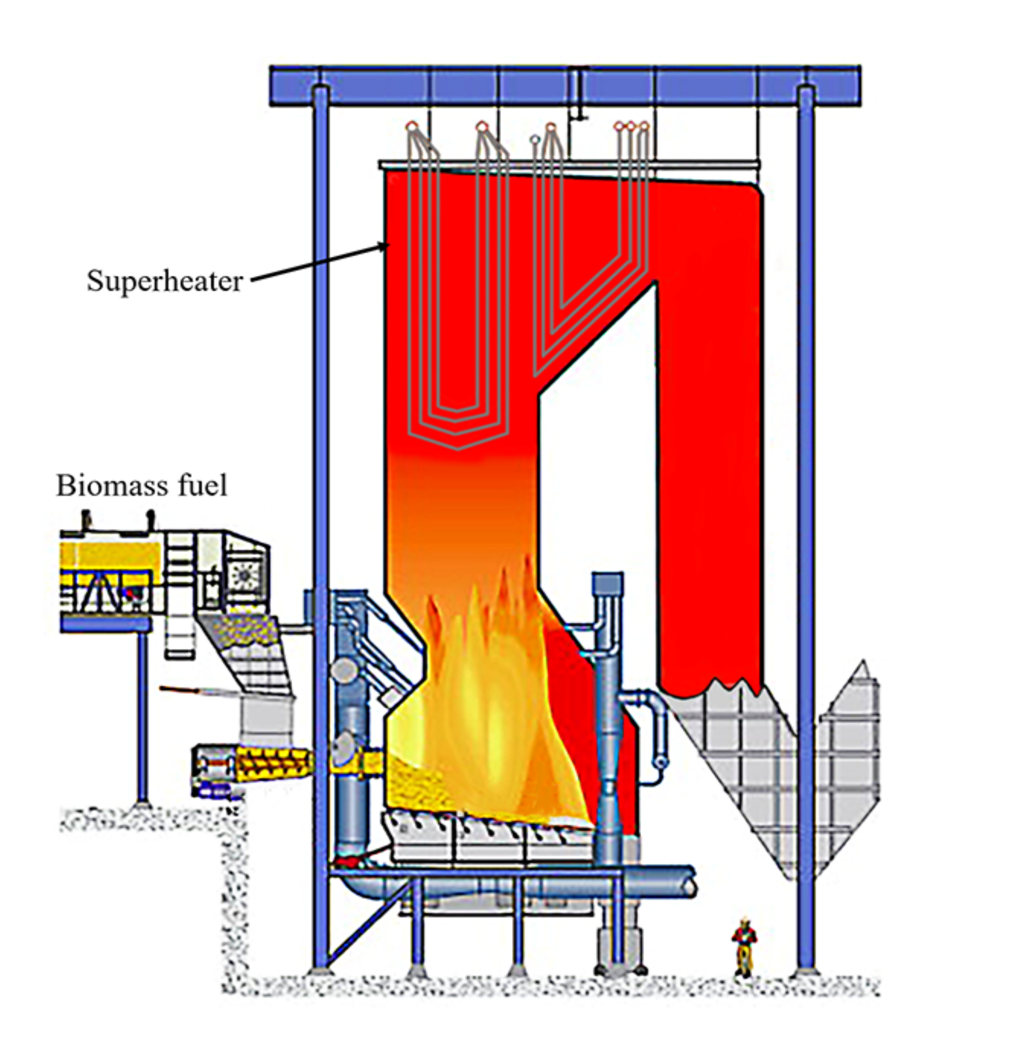
Figure 2.
Outlet steam temperature date and corrosion morphology about the Ni-coated tubes in (a,c) Randers; (b,d) MSK [25].
Figure 2.
Outlet steam temperature date and corrosion morphology about the Ni-coated tubes in (a,c) Randers; (b,d) MSK [25].

Figure 3.
Schematic diagram of a thermal spray process. Controllable air flow and temperature meet different requirements.
Figure 3.
Schematic diagram of a thermal spray process. Controllable air flow and temperature meet different requirements.

Figure 4.
(a) Weight gain of the exposed Ni21Cr and NiAl coatings in 5% O2 + 500 ppm HCl + N2 up to 168 h at 600 °C with and without KCl deposit [62]. (b) The thickness of the formed scale (average of 10 measurements) and mass gain of the samples exposed to KCl deposit at 600 °C for 168 h [58].
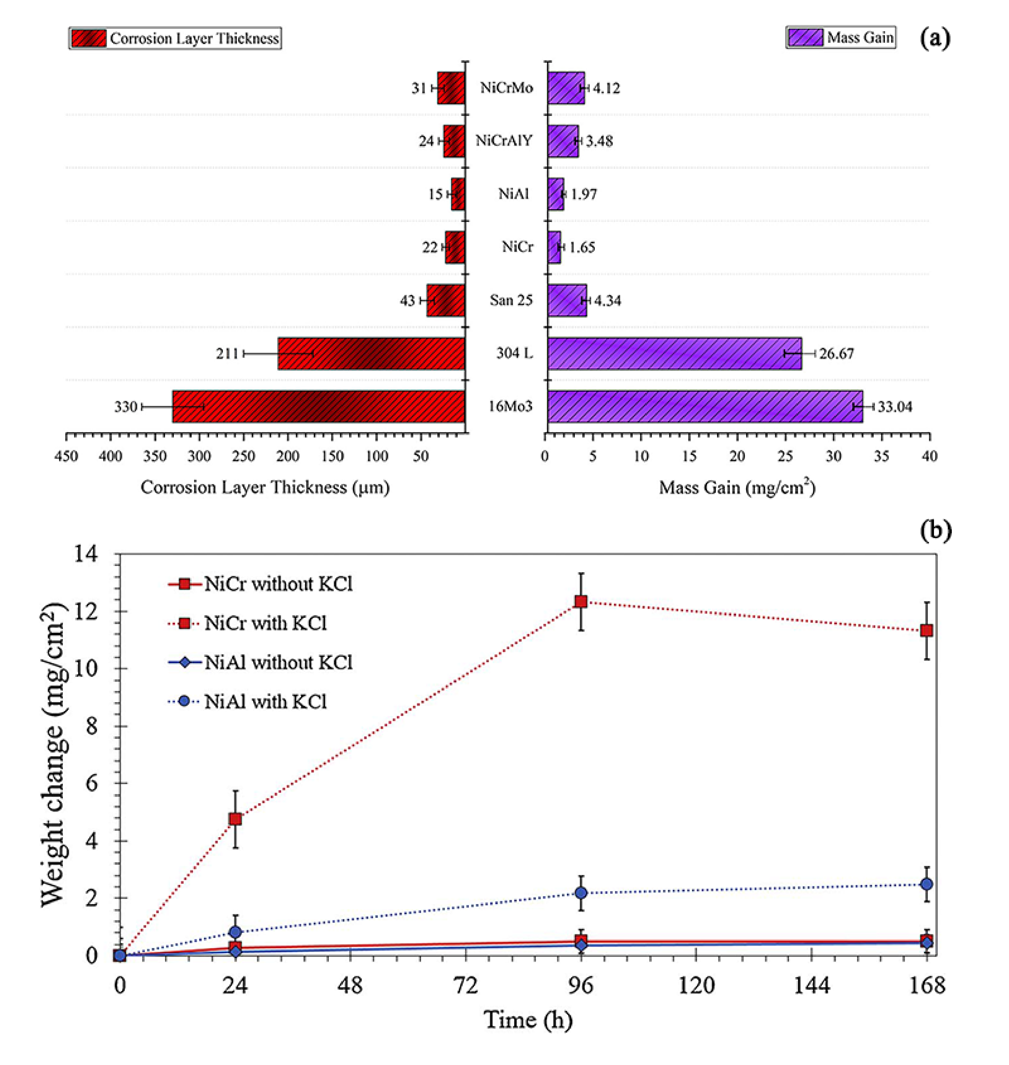
Figure 5.
(a) Cross-sectional SEM micrograph (BSE) of the Ni5Al coating oxidized in 5% O2 + 500 ppm HCl + N2 for 168 h at 600 °C with KCl deposit [58]. (b) Cross-sectional BSE images of Ni31Al coating after corrosion at 700 °C for 250 h in synthetic gas with 500 ppm HCl and 10% KCl ash deposit [49].
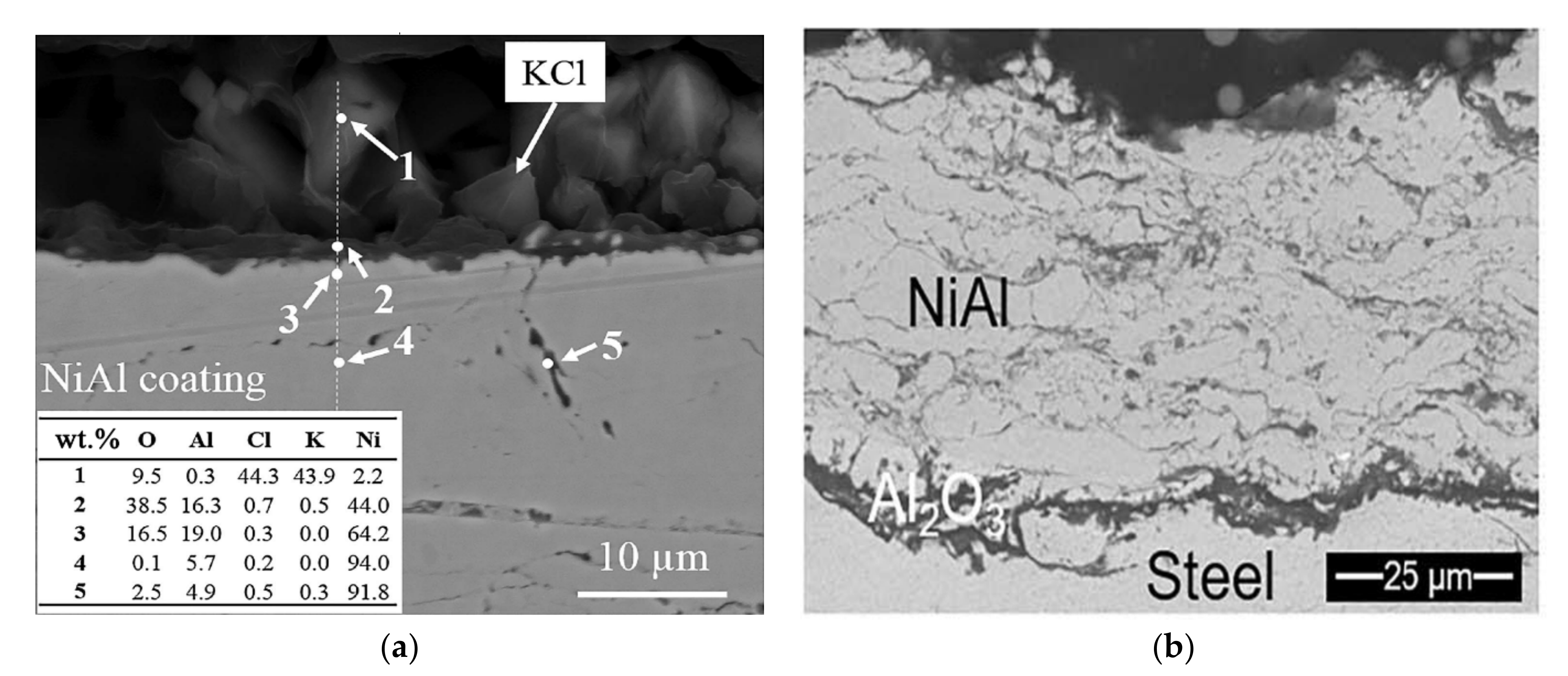
Figure 6.
Mass change of IN625, C276, and NiCrBSiFe after corrosion tests [53].
Figure 6.
Mass change of IN625, C276, and NiCrBSiFe after corrosion tests [53].
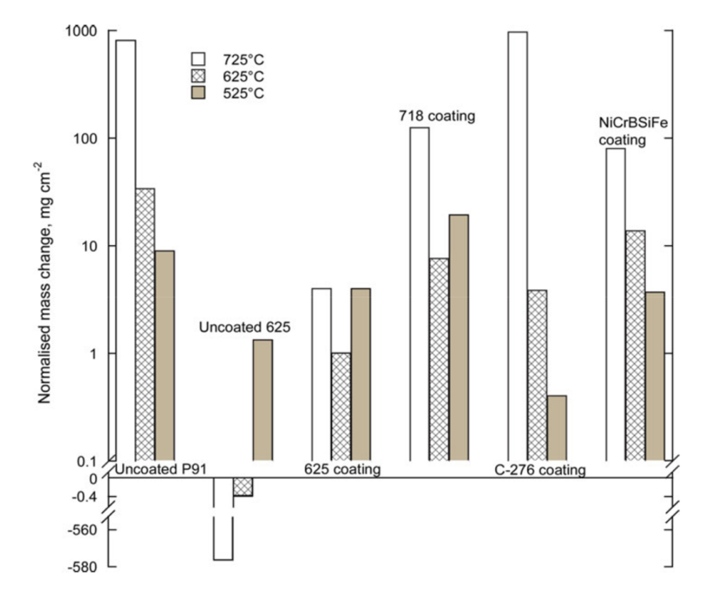
Figure 7.
Maximum thickness values of the oxide/corrosion layers formed during the tests (μm) [50].
Figure 7.
Maximum thickness values of the oxide/corrosion layers formed during the tests (μm) [50].

Figure 8.
The mechanism diagram of metal penetration in the laboratory.
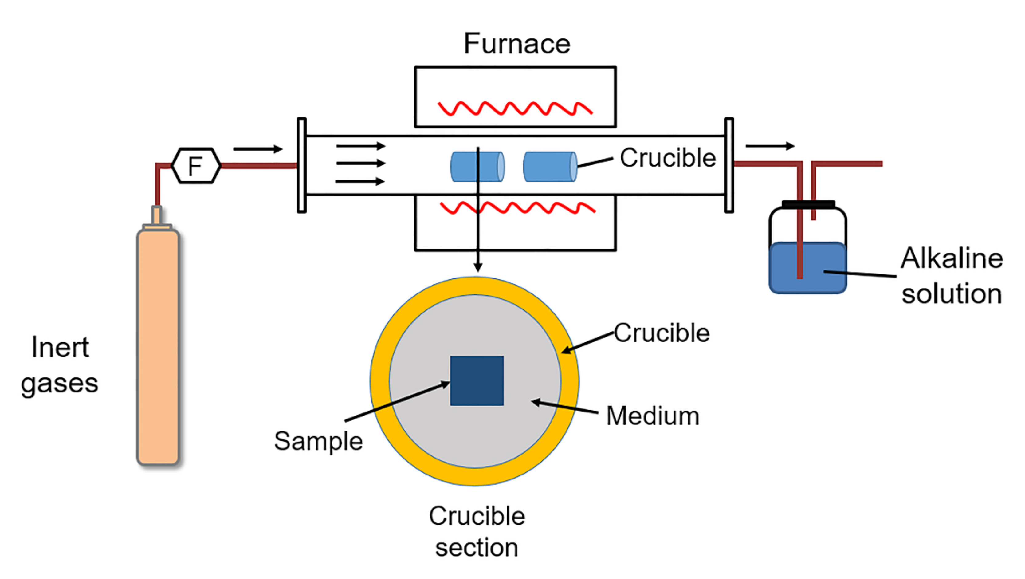
Figure 9.
The schematic diagram of laser cladding. The performance of the coating is controlled by the laser power and feed rate.
Figure 9.
The schematic diagram of laser cladding. The performance of the coating is controlled by the laser power and feed rate.


Table 1.
Biomass and co-firing plants in Denmark [5].
Table 1.
Biomass and co-firing plants in Denmark [5].
| Plant Description | Type | Steam Temp. °C | Pressure MPa | Size MWth | Commissioned |
|---|---|---|---|---|---|
| Haslev | Grate-fired | 440 | 6.7 | 20 | 1989 |
| Slagelse | Grate-fired | 450 | 6.7 | 32 | 1990 |
| Rudkøbing CHP 100% straw | Grate-fired | 450 | 6.1 | 10.7 | 1990 |
| Masnedø CHP-almost 100% straw | Grate-fired | 520 | 9.2 | 33 | 1998 |
| Ensted CHP-100% straw boiler 100% woodchip | Grate-fired | 470 470–540 | 20.1 20.1 | 80 15 | - |
| Maribo Sakskøbing CHP: 100% straw | Grate-fired | 540 | 9.3 | 33 | 2000 |
| Avedøre 2 Bioboiler: 100% straw | Grate-fired | 540 | 30 | 105 | 2001 |
| Fyn 8: 100% straw | Grate-fired | 540 | 12 | 117 | 2009 |
| Grenå 50% CFB straw, 50% coal | CFB | 505 | 9.2 | 80 | 1992 |
| Studstrup suspension fired coal plant modified for coal + 10% straw | Suspension fired | 540 | 25 | 830 | 2002 rebuilt Unit 4 |
| Avedøre II main boiler: oil + gas + wood | Suspension fired | 540-580 | 30 | 800 | 2005 rebuilt Unit 3 2001 |
| Herning Wood + gas | Grate-fired | 515 | 11.5 | 288 | 2002 rebuilt to biomass 2009 |
| Amager I multifuel straw pellets, coal, wood pellets, heavy fuel oil | Suspension fired | 560 | 18 | 350 |
Notes: Combined Heat and Power- CHP; Circulating Fluidized Bed- CFB.
Table 2.
Impurities that influence corrosion damage and corrosivity of boiler combustion gas environment in typical biomass fuels [18].
Table 2.
Impurities that influence corrosion damage and corrosivity of boiler combustion gas environment in typical biomass fuels [18].
| Kind of Biomass Fuels | Sewage Sludge | Wooden Chips | Wheat Straw | Palm Kennel Shell | Coal | Municipal Waste | |
|---|---|---|---|---|---|---|---|
| Contaminants of fuels | Ash | ● | △ | △ | ○ | ● | ● |
| Cl | ● | △ | △ | △ | ● | ○ | |
| S | ● | △ | ● | ○ | △ | ● | |
| Ash constituents | Alkaline metals (Na, K) | △ | △ | ● | △ | ○ | ● |
| Alkaline earth metals (Ca, Mg) | △ | ● | △ | ● | △ | △ | |
| Heavy metals (Zn, Pb) | ○ | ○ | ○ | ○ | ○ | ● | |
| Others (Fe, P) | ● | △ | △ | ○ | ● | △ | |
| Corrosivity of formed environment | Severe | Medium | Severe | Weak | Medium | Severe | |
Notes: Composition ●: Much, △: Much, but fluctuated, ○: A little.
Table 3.
List of preparation technology used by different authors in the biomass/co-fired boilers.
| Preparation Technology | References |
|---|---|
| Thermal spraying | [24,32,36,37,38,39,40,41,42,43,44,45,46,47,48,49,50,51,52,53,54,55,56,57,58,59,60,61,62] |
| Laser cladding | [33,52,54,63] |
| Aluminizing | [16,64,65,66] |
| Physical vapor deposition | [67] |
Table 4.
List of various materials studied by different authors in high-temperature biomass corrosion-related environments.
Table 4.
List of various materials studied by different authors in high-temperature biomass corrosion-related environments.
| Material | Composition (wt.%) | Tech | Temp (°C) | Time (h) | Atmosphere | Salt (mg/cm2) | Mass Change (mg/cm2) | Corrosion Layer Thickness (μm) | Reference |
|---|---|---|---|---|---|---|---|---|---|
| Ni5Al | Ni- < 5.7Al | HVAF | 600 | 168 | 5O2 + Bal.N2 (vol.%) + 500 vppm HCl | 0.1 KCl | 2.49 | ~2 | [58] |
| Air | 0.1 KCl | 1.97 | ~15 | [62] | |||||
| 5O2 + 20H2O + Bal.N2 (vol.%) | 1 KCl | −0.25 | ~4 | [61] | |||||
| HVOF | 550 | 672 | 8O2 + 30H2O + 2N2 + 60CO2 (vol.%) + 400 vppm HCl + 2 vppm SO2 | 0.4~0.7 (45KCl + 55K2SO4 wt.%) | ~32 | Failure | [60] | ||
| Ni31Al | Ni-31Al | HVOF | 700 | 250 | 5O2 + Bal.N2 (vol.%) + 500ppm HCl | 30 (10KCl + 90Kaolinite wt.%) | - | ~3 | [49] |
| APS | 800 | 280 | 99.8Ar + 0.2Cl2(vol.%) + 3 ppm O2 | - | - | ~75 | [24] | ||
| C-276 | Ni-15.55Cr-16.48Mo-5.09Fe-3.81W | HVOF | 525 | 168 | 9O2 + 7H2O + 84N2(vol.%) + 175 vppm HCl | Embedded in salt mixture (45.1K2SO4 + 54.9KCl wt.%) | 0.4 | ~3 | [53] |
| 625 | 3.9 | ~40 | |||||||
| 725 | 972 | >10,000 | |||||||
| NiCrBSiFe | Ni-17.2Cr-3.7Si-3.1B-4.6Fe-0.8C | HVOF | 525 | 3.7 | ~10 | ||||
| 625 | 13.8 | - | |||||||
| 725 | 79.9 | ~250 | |||||||
| Alloy 718 | Ni-18.78Cr-17.9Fe-3.04Mo-5.26Nb-0.48Al | HVOF | 525 | 19.4 | ~50 | ||||
| 625 | 7.7 | ~25 | |||||||
| 725 | 124.8 | ~230 | |||||||
| Ni20Cr | Ni-20Cr | HVOF | 550 | 672 | 60CO2 + 30H2O + 8O2 + 2N2(vol.%) + 400 vppm HCl + 2 vppm SO2 | 0.4~0.7 (45KCl + 55K2SO4 wt.%) | ~3 | 1–5 (528 h) | [60] |
| Ni21Cr | Ni-21Cr | HVAF | 600 | 168 | 5O2 + Bal.N2 (vol.%) + 500 vppm HCl | 0.1 KCl | 11.32 | ~18.75 | [58] |
| Air | 0.1 KCl | 1.65 | ~22 | [62] | |||||
| 5O2 + 20H2O + Bal.N2 (vol.%) | 1 KCl | 2.5 | ~17 | [61] | |||||
| C22 | Ni-21.3Cr-13.2Mo-3W-2.93Fe-2Co | LC | 550 | 96 | Air | Embedded in salt mixture (98.6KCl + 1.4NaCl/95.5KCl + 4.5NaCl wt.%) | 17/10.5 | - | [33] |
| 600 | 68/148 | - | |||||||
| 650 | 177.8/177.7 | - | |||||||
| 700 | 160/56 | - | |||||||
| 750 | 50/46 | - | |||||||
| 650 | 168 | 5O2 + 12CO2 + 0.05HCl + Bal.N2 (vol.%) | - | 0.1 | - | [63] | |||
| 700 | 0.15 | - | |||||||
| Diamalloy 4006 | Ni- > 21.2Cr- > 10W- > 9.0Mo- > 4.2Cu- > 0.8C- > 0.75B | HVOF-CJS | 600 | 168 | Air | Embedded in salt mixture (50 K2SO4 + 50KCl mol.%) | - | 7 | [51] |
| Air + 30H2O (vol.%) | - | 7 | |||||||
| 575 | 168 | 5O2 + 10H2O + Bal.N2 (vol.%) | Spray deposition (6.5NaCl + 59Na2SO4 + 34.5KCl wt.%) | - | ~105 | [50] | |||
| 625 | - | ~25 | |||||||
| 550 | 1300 | Actual boiler | - | 1~2 | [56] | ||||
| 750 | - | Failure | |||||||
| HVOF-DJ | 575 | 168 | 5O2 + 10H2O + Bal.N2 (vol.%) | Spray deposition (6.5NaCl + 59Na2SO4 + 34.5KCl wt.%) | - | ~20 | [50] | ||
| 625 | - | ~25 | |||||||
| NiCrAlY | Ni-21Cr-7Al-1Y | HVAF | 600 | 168 | Air | 0.1 KCl | 3.48 | ~24 | [62] |
| 5O2 + 20H2O + Bal.N2 (vol.%) | 1 KCl | 0.4 | ~3 | [61] | |||||
| 5O2 + Bal.N2 (vol.%) + 500 vppm HCl | 0.1 KCl | 1.49 | ~10 | [46] | |||||
| HVOF | 200 | 17520 | Actual boiler | - | 0 | [40] | |||
| 650 | 1000 | 4O2 + 8H2O + 14CO2 + 73.8N2 (vol.%) + 400 vppm HCl + 1300 vppm SO2 | 20 (37.5Na2SO4 + 37.5K2SO4 + 25 Fe2O3 mol.%) | ~170 | >250 (50% probability) | [48] | |||
| 20(30Na2SO4 + 30K2SO4 + 20Fe2O3 + 20Kaolinite mol.%) | ~60 | 20 (50% probability) | |||||||
| 20(22.5Na2SO4 + 22.5K2SO4 + 15Fe2O3 + 40Kaolinite mol.%) | ~42 | 18 (50% probability) | |||||||
| 20(15Na2SO4 + 15K2SO4 + 10Fe2O3 + 60 Kaolinite mol.%) | ~20 | >7 (50% probability) | |||||||
| 20(7.5Na2SO4 + 7.5K2SO4 + 5Fe2O3 + 80Kaolinite mol.%) | ~12 | >7 (50% probability) | |||||||
| 20(37.5Na2SO4 + 37.5K2SO4 + 25Fe2O3 mol.%) | - | 180 (50% probability) | [47] | ||||||
| APS | - | 210 (50% probability) | |||||||
| Ni21Cr9Mo | Ni-21Cr-9Mo | HVAF | 600 | 168 | Air | 0.1 KCl | 4.12 | ~31 | [62] |
| Ni21Cr9Mo-SiO2 | SiO2-containg Ni21Cr9Mo | HVAF | 600 | 168 | 5O2 + Bal.N2 (vol.%) + 500 vppm HCl | 0.1 KCl | 0.67 | ~15 | [46] |
| IN625 | Ni- < 21.5Cr- < 9Mo- < 3.7Nb + Ta- < 2.5Fe- < 0.2Si- < 0.1Mn | HVOF-CJS | 575 | 168 | 5O2 + 10H2O + Bal.N2 (vol.%) | Spray deposition (6.5NaCl + 59Na2SO4 + 34.5KCl wt.%) | - | ~150 | [50] |
| 625 | - | ~40 | |||||||
| HVOF-DJ | 575 | - | ~75 | ||||||
| 625 | - | ~20 | |||||||
| 550 | 5900 | Actual boiler | - | 6~18 | [44,56] | ||||
| 750 | - | 323~434 | |||||||
| 110 | 17520 | - | 0 | [40] | |||||
| HVOF | 650 | 1000 | 4O2 + 8H2O + 14CO2 + 73.8N2 (vol.%) + 400 vppm HCl + 1300 vppm SO2 | 20 (37.5Na2SO4 + 37.5K2SO4 + 25Fe2O3 mol.%) | ~120 | 125 (50% probability) | [48] | ||
| 20(30Na2SO4 + 30K2SO4 + 20Fe2O3 + 20Kaolinite mol.%) | ~75 | 90 (50% probability) | |||||||
| 20(22.5Na2SO4 + 22.5K2SO4 + 15Fe2O3 + 40Kaolinite mol.%) | ~58 | 38 (50% probability) | |||||||
| 20(15Na2SO4 + 15K2SO4 + 10Fe2O3 + 60 Kaolinite mol.%) | ~48 | <10 (50% probability) | |||||||
| 20(7.5Na2SO4 + 7.5K2SO4 + 5Fe2O3 + 80Kaolinite mol.%) | ~23 | <10 (50% probability) | |||||||
| 20(37.5Na2SO4 + 37.5K2SO4 + 25Fe2O3 mol.%) | - | 175 (50% probability) | [47] | ||||||
| 525 | 168 | 9O2 + 7H2O + Bal.N2(vol.%) + 175 vppm HCl | Embedded in salt mixture (45.1K2SO4 + 54.9KCl wt.%) | 4 | - | [53] | |||
| 625 | 1 | ~3 | |||||||
| 725 | 4 | ~5 | |||||||
| 400 | 360 | Air | (52KCl + 48ZnCl2 wt.%) | - | ~10 | [41] | |||
| 550 | 168 | Air + 12H2O (vol.%) | KCl | - | 4.55 | [37] | |||
| TWAS | - | 1.19 | |||||||
| CS | - | 9.25 | |||||||
| HVAF | - | 11.58 | |||||||
| APS | 650 | 1000 | 4O2 + 8H2O + 14CO2 + 73.8N2 (vol.%) + 400 vppm HCl + 1300 vppm SO2 | 20(37.5Na2SO4 + 37.5K2SO4 + 25Fe2O3 mol.%) | - | 110 (50% probability) | [47] | ||
| Carpenter 6119 | Ni-22.58Cr-12.77Mo-4Fe-2.63W-0.26Si | HVOF | 400 | 360 | Air | 5(52KCl + 48ZnCl2 wt.%) | - | ~18 | [41] |
| NiCr16Mo | Ni-24Cr-16.5Mo-1.5Fe-0.5Al | HVOF | 110 | 17520 | Actual boiler | - | 1 | [40] | |
| Ni45Cr | Ni-43.3Cr-0.41Ti-0.02C | WAS | 550 | 168 | Air + 30H2O (vol.%) | Embedded in salt mixture (50K2SO4 + 50KCl mol.%) | - | 5 | [51] |
| Air | 2 | ||||||||
| 600 | Air + 30H2O (vol.%) | 12 | |||||||
| Air | 30 | ||||||||
| Ni45Cr | Ni- > 45Cr < 2.2Si < 1.1Fe | HVOF | 600 | 168 | Air + 30H2O (vol.%) | Embedded in salt mixture (50K2SO4 + 50KCl mol.%) | - | 9 | [51] |
| Air | 9 | ||||||||
| HVOF-CJS | 575 | 168 | 5O2 + 10H2O + Bal.N2 (vol.%) | Spray deposition (6.5NaCl + 59Na2SO4 + 34.5KCl wt.%) | - | ~110 | [50] | ||
| 625 | - | ~60 | |||||||
| 550 | 5900 | Actual boiler | - | 3~6 | [44,56] | ||||
| 750 | - | 6~31 | |||||||
| HVOF-DJ | 575 | 168 | 5O2 + 10H2O + Bal.N2 (vol.%) | Spray deposition (6.5NaCl + 59Na2SO4 + 34.5KCl wt.%) | - | ~55 | [50] | ||
| 625 | - | ~40 | |||||||
| HVOF | 650 | 1000 | 4O2 + 8H2O + 14CO2 + 73.8N2 (vol.%) + 400 HCl + 1300 SO2 (vppm) | 20(37.5Na2SO4 + 37.5K2SO4 + 25Fe2O3 mol.%) | - | ~87 (50% probability) | [47] | ||
| APS | - | 13 (50% probability) | |||||||
| Ni50Cr | Ni-46Cr-1.1Fe-0.5Si-0.1C (cold) | HVOF-DJ | 550 | 168 | Air + 30H2O (vol.%) | Embedded in salt mixture (50K2SO4 + 50KCl mol.%) | - | 16 | [51] |
| Air | 5 | ||||||||
| Ni-46Cr-1.1Fe-0.5Si-0.1C (hot) | Air + 30H2O (vol.%) | 39 | |||||||
| Air | 16 | ||||||||
| Ni-46Cr-1.1Fe-0.5Si-0.1C (cold) | 600 | Air + 30H2O (vol.%) | Embedded in salt mixture (50K2SO4 + 50KCl mol.%) | - | 52 | ||||
| Air | 21 | ||||||||
| Ni-46Cr-1.1Fe-0.5Si-0.1C (hot) | Air + 30H2O (vol.%) | 56 | |||||||
| Air | 25 | ||||||||
| Ni- > 45Cr-2.1Si-1.1Fe | 550 | 5900 | Actual boiler | - | 4~8 | [44] | |||
| 750 | - | 20~65 | |||||||
| Ni50Cr | Ni-46Cr-2Si-1Fe-0.1C | HVOF-Liquid | 700 | 250 | 5O2 + Bal.N2 (vol.%) + 500 ppm HCl | 14 ± 1 KCl | - | ~40 | [54] |
| 650 | 1000 | 4O2 + 8H2O + 14CO2 + 73.8N2 (vol.%) + 400 vppm HCl + 1300 vppm SO2 | 20 (37.5Na2SO4 + 37.5K2SO4 + 25Fe2O3 mol.%) | ~130 | ~120 (50% probability) | [48] | |||
| 20(30Na2SO4 + 30K2SO4 + 20Fe2O3 + 20Kaolinite mol.%) | ~78 | <15 (50% probability) | |||||||
| 20(22.5Na2SO4 + 22.5K2SO4 + 15Fe2O3 + 40Kaolinite mol.%) | ~55 | <15 (50% probability) | |||||||
| 20(15Na2SO4 + 15K2SO4 + 10Fe2O3 + 60 Kaolinite mol.%) | ~38 | <15 (50% probability) | |||||||
| 20(7.5Na2SO4 + 7.5K2SO4 + 5Fe2O3 + 80Kaolinite mol.%) | ~22 | <15 (50% probability) | |||||||
| 575 | 168 | 5O2 + 10H2O + Bal.N2 (vol.%) | Spray deposition (6.5NaCl + 59Na2SO4 + 34.5KCl wt.%) | - | 2.71 (mm/year) | [45] | |||
| 625 | - | 1.56 (mm/year) | |||||||
| 550 | 5900 | Actual boiler | - | 0.01 (mm/year) | |||||
| 750 | - | 0.1 (mm/year) | |||||||
| HVOF-Gas | 700 | 250 | 5O2 + Bal.N2 (vol.%) + 500 ppm HCl | 14 ± 1 KCl | - | ~45 | [54] | ||
| LC | - | ~9 | |||||||
| NiCrTi | Ni- < 46Cr- < 1Ti | AS | 550 | 5900 | Actual boiler | - | 10~22 | [44,56] | |
| 750 | - | 16~65 | |||||||
| Ni50Cr | Ni-50Cr-0.3Si-0.2C | CS | 700 | 250 | 5O2 + Bal.N2 (vol.%) + 500 ppm HCl | 14 ± 1 KCl | - | ~57.5 | [54] |
| Fe13Cr | Fe-13.2Cr-0.39Si-0.25Ni-0.46Mn-0.41C | WAS | 550 | 168 | Air + 30H2O (vol.%) | Embedded in salt mixture (50K2SO4 + 50KCl mol.%) | - | 48 | [51] |
| Air | 57 | ||||||||
| 600 | Air + 30H2O (vol.%) | 72 | |||||||
| Air | 146 | ||||||||
| Diamalloy 1003 | Fe-16.06Cr-9.88Ni-2.04Mo-1.21Mn | HVOF | 400 | 360 | Air | 5(52KCl + 48ZnCl2 wt.%) | - | ~13 | [41] |
| SHS 7574 | Fe-17.78Cr-14.24Mo-5.9W-2.96B-2.1Mn-1.36Si-0.88C | HVOF | 700 | 250 | 5O2 + Bal.N2 (vol.%) + 500 ppm HCl | 14 ± 1 KCl | - | 276 (Failure) | [52] |
| LC | - | 557 ± 33 | [52] | ||||||
| FeCr | Fe- < 20Cr | HVOF | 650 | 300 | 2O2 + 29H2O + 44CO2 + 0.6SO2 + 0.2HCl + N2 (vol.%) | Embedded in (84CaCO3 + 15CaSO4 + 1KCl wt.%) | - | ~800 | [64] |
| Fe- > 20Cr | - | ~180 | |||||||
| FeCrAl | Fe-21.7Cr-5.9Al-0.83Si-0.76Mn | HVOF | 700 | 1000 | 4O2 + 8H2O + 14CO2 + 73.8N2 (vol.%) + 400 vppm HCl + 1300 vppm SO2 | 20(37.5Na2SO4 + 37.5K2SO4 + 25Fe2O3 mol.%) | ~70 | ~85 (50% probability) | [55] |
| 750 | ~125 | >250 (50% probability) | |||||||
| 800 | ~170 | ~300 (50% probability) | |||||||
| 650 | - | 140 (50% probability) | [47] | ||||||
| APS | 650 | - | 70 (50% probability) | ||||||
| SHS9172 | Fe- < 25Cr- < 15W- < 12Nb- < 6Mo- < 4C- < 3Mn- < 2Si | HVOF-CJS | 600 | 168 | Air + 30H2O (vol.%) | Embedded in salt mixture (50K2SO4 + 50KCl mol.%) | - | 22 | [51] |
| Air | 6 | ||||||||
| 575 | 5O2 + 10H2O + Bal.N2 (vol.%) | Spray deposition (6.5NaCl + 59Na2SO4 + 34.5KCl wt.%) | - | ~30 | [50] | ||||
| 625 | - | ~35 | |||||||
| HVOF-DJ | 575 | - | ~25 | ||||||
| 625 | - | ~25 | |||||||
| 575 | - | 1.30 (mm/year) | [45] | ||||||
| 625 | - | 1.25 (mm/year) | |||||||
| 550 | 5900 | Actual boiler | - | 23~80 | [44,45,56] | ||||
| 750 | - | 55~111 | |||||||
| SHS7174wire | >45Fe- < 30Cr- < 10Mo- < 5B- < 4W- < 2C- < 2Mn- < 2Si | WAS | 550 | 168 | Air + 30H2O (vol.%) | Embedded in salt mixture (50K2SO4 + 50KCl mol.%) | - | 2 | [51] |
| Air | 3 | ||||||||
| 600 | 168 | Air + 30H2O (vol.%) | 10 | ||||||
| Air | 5 | ||||||||
| Fe50Cr | Fe-50Cr | HVOF | 550 | 672 | 60CO2 + 30H2O + 8O2 + 2N2 (vol.%) + 400 vppm HCl + 2 vppm SO2 | 0.4~0.7 (45KCl + 55K2SO4 wt.%) | 6 | 4–10 (528 h) | [60] |
| Fe-Cr-Al | 0.4~59.4Fe-1.4~99.4Cr-0.3~43.2Al | PVD | 550 | 150 | Air + 315 vppm HCl | - | −0.88~0.65 | <1 | [67] |
| Slurry aluminide | Al + inorganic compounds | D | 550 | 672 | 8O2 + 30H2O + 60CO2 + 2N2 (vol.%) + 400 vppm HCl + 2 vppm SO2 | 0.4~0.7 (45KCl + 55K2SO4 wt.%) | 3 | 1–2 (528 h) | [60] |
| Cr enriched aluminide | Cr + Al slurry | 7 | ~6 (528 h) | ||||||
| FeCr + Al | Fe- < 20Cr + overaluminized | HVOF + D | 650 | 300 | 2O2 + 29H2O + 44CO2 + 0.6SO2 + 0.2HCl + Bal.N2 (vol%) | Embedded in (84CaCO3 + 15CaSO4 + 1KCl wt.%) | - | ~10 | [64] |
| Fe- > 20Cr + overaluminized | - | ~8 | |||||||
| P91 | 10% Al, 1% NH4Cl, 89% Al2O3 | D | 650 | 300 | Air | Embedded in salt mixture (50K2SO4 + 50KCl mol.%) | - | 20 | [16] |
| 10Al + 10Fe + 6AlCl3 + 74Al2O3 mol.% | 600 | 168 | 1 mm KCl | - | ~1 | [66] | |||
| 10Al + 6AlCl3 + 84Al2O3 mol.% | - | >40 | |||||||
| 17Cr alloy | 5% Al, 0,5% NH4Cl, 94,5% Al2O3 | D | 650 | 300 | Embedded in salt mixture (50K2SO4 + 50KCl mol.%) | - | 30 | [16] | |
| Alloy 800 | - | 30 | |||||||
| In 617 | - | 60 | |||||||
| Ni | 10Al + 6AlCl3 + 84Al2O3 mol.% | D | 600 | 168 | 1 mm KCl | - | <1 | [66] | |
| TP347H | 10Al + 8AlCl3 + 82Al2O3 mol.% | D | 540 | 6757 | Actual boiler | - | Failure | [65] | |
Laser cladding-LC; High-velocity oxygen fuel spray -HVOF; High-velocity air fuel spray-HVAF; Wire arc spray-WAS; Cold sprayed-CS; Air plasma-sprayed-APS; Arc spray-AS; Diffusion-D; Physical vapor deposition-PVD; Diamond jet hybrid-DJ; Carbide jet spray-CJS; Median metal loss (50% cumulative probability): 50% probability.
Publisher’s Note: MDPI stays neutral with regard to jurisdictional claims in published maps and institutional affiliations. |
© 2020 by the authors. Licensee MDPI, Basel, Switzerland. This article is an open access article distributed under the terms and conditions of the Creative Commons Attribution (CC BY) license (http://creativecommons.org/licenses/by/4.0/).
Share and Cite
MDPI and ACS Style
Wu, D.; Yuan, Z.; Liu, S.; Zheng, J.; Wei, X.; Zhang, C. Recent Development of Corrosion Factors and Coating Applications in Biomass Firing Plants. Coatings 2020, 10, 1001. https://doi.org/10.3390/coatings10101001
AMA Style
Wu D, Yuan Z, Liu S, Zheng J, Wei X, Zhang C. Recent Development of Corrosion Factors and Coating Applications in Biomass Firing Plants. Coatings. 2020; 10(10):1001. https://doi.org/10.3390/coatings10101001
Chicago/Turabian StyleWu, Duoli, Ziyi Yuan, Su Liu, Jiayin Zheng, Xinlong Wei, and Chao Zhang. 2020. "Recent Development of Corrosion Factors and Coating Applications in Biomass Firing Plants" Coatings 10, no. 10: 1001. https://doi.org/10.3390/coatings10101001
Note that from the first issue of 2016, this journal uses article numbers instead of page numbers. See further details here.